

Johnson Controls VG1xA5Gx, VG1xA5Kx, VG1xA5Lx, VG1xA5Jx, VG1xA5Hx Installation Instructions Manual
...Page 1
VG1000 Series Flanged Ball Valves
14- 1352-6, Rev. G
Installation Instructions
VG12A5xx, VG18A5xx
Refer to the QuickLIT website for the most up-to-date version of this document.
Part No. 14-1352-6, Rev. G
Issued October 2016
Applications
The VG1000 Series Flanged Ball Valves are designed
to regulate hot and chilled water , 50/50 glycol solutions,
and 25 psig steam in HVAC systems.
IMPORTANT: The VG1000 Series Flanged Ball
Valve is intended to control saturated steam, hot
water, and chilled water flow under normal operating
conditions. Where failure or malfunction of the ball
valve could lead to personal injury or property
damage to the controlled equipment or other
property, additional precautions must be designed
into the control system. Incorporate and maintain
other devices, such as supervisory or alarm systems
or safety or limit controls, intended to warn of or
protect against failure or malfunction of the ball
valve.
IMPORTANT: Le VG1000 Series Flanged Ball Valve
est destiné à réguler un débit saturated steam, hot
water, and chilled water dans des conditions
normales de fonctionnement. Lorsqu'une défaillance
ou un dysfonctionnement du ball valve risque de
provoquer des blessures ou d'endommager
l'équipement contrôlé ou un autre équipement, la
conception du système de contrôle doit intégrer des
dispositifs de protection supplémentaires. Veiller
dans ce cas à intégrer de façon permanente
d'autres dispositifs, tels que des systèmes de
supervision ou d'alarme, ou des dispositifs de
sécurité ou de limitation, ayant une fonction
d'avertissement ou de protection en cas de
défaillance ou de dysfonctionnement du ball valve.
To minimize heat transfer in steam applications, wrap
the valve and piping with insulation. Allow at least 4 in.
(102 mm) of clearance from the top of the shaft to
remove the actuator (as noted in Table 1).
When mounting the actuator in the field and before
installing the actuator, use an adjustable wrench to
manually rotate the valve stem several times. This
rotation breaks the torque th at may have built up during
long-term storage.
IMPORTANT: Do not attempt to manually rotate the
drive shaft while the actuator is installed without fir st
releasing the actuator gears. Manually rotating the
drive shaft without releasing the actuator gears may
result in permanent damage to the actuator.
IMPORTANT: Take care to prevent foreign material
such as weld slag, thread burrs, metal chips, and
scale from entering the piping system. This de br is
can damage or severely impede the operation of the
valve by embedding itself in the seats, scoring the
valve, and ultimately resulting in seat leakage. If the
debris becomes embedded in the seats, subseque nt
flushing and filtering of the piping system with the
valve installed does not remedy the problem.
For detailed installation information about using
specific equipment, refer to the appropriate
documentation from the following list.
• M9108, M9116, M9124, and M9132 Series Ele ctric
Non-Spring Return Actuators Installation
Instructions (Part No. 34-636-399)
Installation
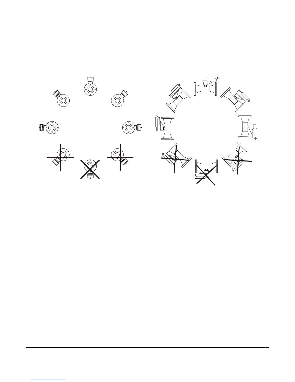
Install the VG1000 Series Flanged Ball Valves with the
actuator at or above the centerline of the horizontal
piping, as shown in Figure 1.
IMPORTANT: In steam applications, install the
valve with the stem horizontal to the piping. Failure
to follow these guidelines may shorten the life of the
actuator.
VG1000 Series Flanged Ball Valves Installation Instructions
• M9220-AGx-3 Series Floating Electric Spring
Return Actuators Installation Instructions
(Part No. 34-636-1689)
• M9220-Bxx-3 Series On/Off Electric Spring Return
Actuators Installation Instructions
(Part No. 34-636-1239)
• M9220-GGx-3 Series Proportional Electric Spring
Return Actuators Installation Instructions
(Part No. 34-636-1697)
1
Page 2
• M9000-330 and M9000-340 Series We ather Shield
Figure 1: Recommended Mounting Positions for Non-Steam Applications
F
I
G
.
V
G
1
0
0
0
-
i
i
0
1
A
AB
Enclosures Installation Instructions
(Part No. 14-1330-26)
• M9000-51x Series Valve Linkage Kits Installation
Instructions (Part No. 14-1201-13)
B
A
A
B
A
A
B
A
A
A
B
A
A
A
B
A
A
B
A
A
B
VG1000 Series Flanged Ball Valves Installation Instructions
2
Page 3
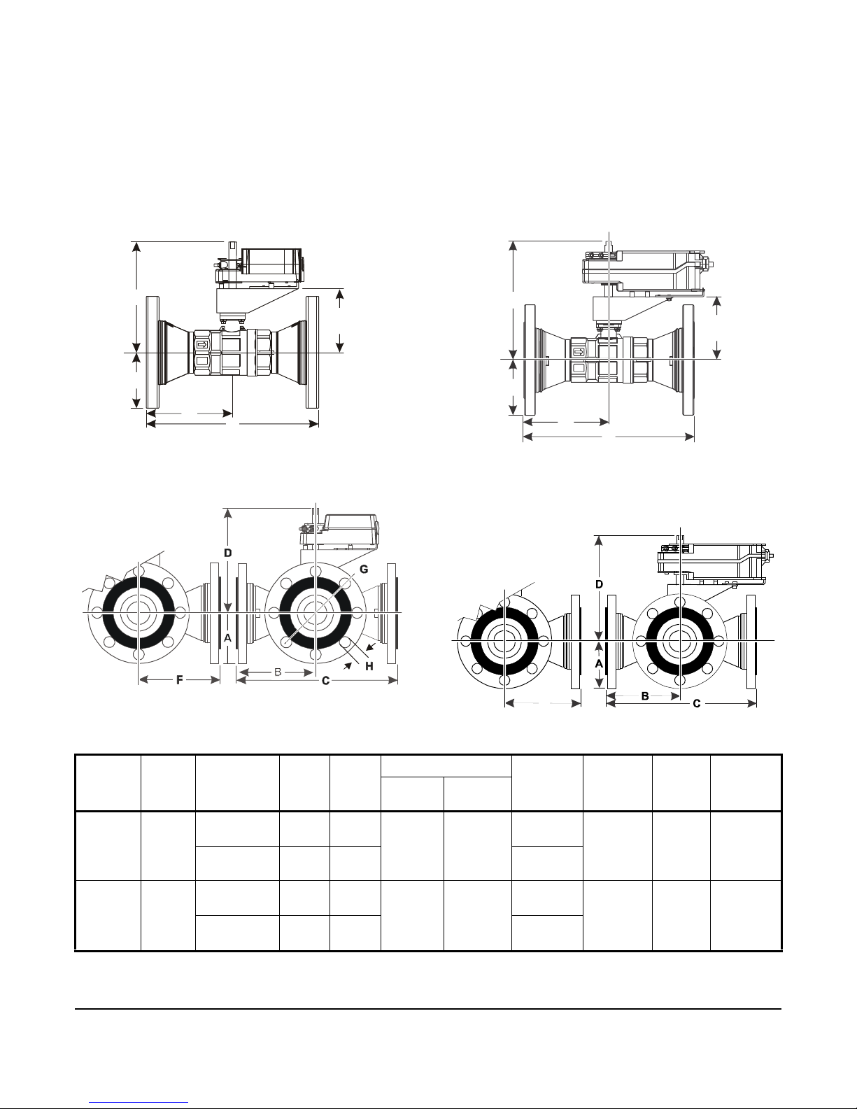
Dimensions
Figure 2: M9124 Actuated VG12A5xx
Two-Way Series Ball Valves, in. (mm)
FIG:M9000-ii02
A
B
C
D
Figure 3: M9124 Actuated
VG18A5xx Three-Way Series Ball Valves
FIG:VG1000 -1103
Figure 4: M9220 Actuated VG12A5x x
Two-Way Series Ball Valves, in. (mm)
5.17
(131)
A
B
C
D
FIG:VG1000-ii04
Figure 5: M9220 Actuated
VG18A5xx Three-Way Series Ball Valves
FIG:VG1000-1105
F
See Figure 2 for VG12A5xx Two-Way Series Flanged
Ball Valves with M9124 Series Actuators dimensions.
See Figure 3 for VG18A5xx Three-Way Series Flanged
Ball Valves with M9124 Series Actuators dimensions.
See Table 1 for specific model dimensions.
5.17
(131)
See Figure 4 for VG12A5xx Two-Way Series Flanged
Ball Valves with M9220 Series Actuators dimensions.
See Figure 5 for VG18A5xx Three-Way Series Flanged
Ball Valves with M9220 Series Actuators dimensions.
See Table 1 for specific model dimensions.
Table 1: VG1xA5xx Series Ball Valves Dimensions, in. (mm) (Part 1 of 2)
Valve
Size,
A Valve
Code
in. (DN)
2-1/2
(DN65)
3 (DN80) 3.75
3.50
(89)
(95)
VG1xA5Gx 5.71
VG1xA5Kx 3.60
VG1xA5Hx 6.10
VG1xA5Lx 4.30
VG1000 Series Flanged Ball Valves Installation Instructions
BC D F G
(Bolt
Circle)
5.50
(140)
6.00
(152)
(145)
(92)
(155)
(110)
1 1 .42
(290)
7.25
(184)
12.20
(310)
8.70
(220)
M9124
8.89
(226)
8.90
(226)
1
M9220
9.64
(245)
9.65
(245)
1
5.87
(149)
6.73
(171)
6.26
(159)
6.77
(172)
3
H Number
of Bolts
0.75
(19)
0.75
(19)
4
4
Page 4

Table 1: VG1xA5xx Series Ball Valves Dimensions, in. (mm) (Part 2 of 2)
Figure 6: Actuated VG12A5xx Two-Way Series
Ball Valves with M9000-3 30 Weathershield
Dimensions, in. (mm)
AAB
A
B
D
5.17
(131)
FIG-VG100 0-ii06
C
Figure 7: Actuated VG18A5xx Three-W ay Series
Ball Valves with M9000-330 Weathershield
F
Valve
Size,
in. (DN)
4
(DN100)
5
(DN125)
6
(DN150)
1. Allow a minimum of 4 in. clearance above the shaft to remove the actuator.
A Valve
4.50
(114)
5.00
(127)
5.50
(140)
VG1xA5Jx 6.89
VG1xA5MW 5.24
VG1xA5NY 6.25
VG1xA5PZ 7.25
Code
BC D F G
(175)
(133)
(159)
(184)
13.77
(350)
10.50
(266)
12.52
(318)
14.50
(368)
M9124
8.90
(226)
9.90
(251)
9.90
(251)
9.90
(251)
1
M9220
9.65
(245)
10.63
(270)
10.63
(270)
10.63
(270)
1
7.05
(179)
8.27
(210)
9.13
(232)
9.90
(251)
(Bolt
Circle)
7.50
(191)
8.50
(217)
9.50
(242)
H Number
of Bolts
0.75
(19)
0.87
(22)
0.87
(22)
8
8
8
See Figure 6 for VG12A5xx Two-Way Series Flanged
Ball Valves with the M9124 Series Non-Spring Return
Actuators dimensions. See Figure 7 for VG18A5xx
Three-Way Series Flanged Ball Valves with the M9124
Series Non-Spring Return Actuators dimensions. Each
drawing includes dimensions for the field-installed
M9000-330 Weathershield. See Table 2 for specific
model dimensions.
FIG-VG100 0-ii07
See Figure 8 for VG12A5xx Two-Way Series Flanged
Ball Valves with the M9220 Series Spring Return
Actuators dimensions. See Figure 9 for the VG18A5xx
Three-Way Series Flanged with the M9220 Series
Spring Return Actuators dimensions. Each drawing
includes dimensions for the field-installed M9000-340
Weathershield. See Table 2 for specific model
dimensions.
VG1000 Series Flanged Ball Valves Installation Instructions
4
Page 5

Figure 8: Actuated VG12A5xx Two-Way Series
Ball Valves with M9000-340 Weathershield
Dimensions, in. (mm)
AAB
5.17
(131)
A
B
D
C
FIG:VG1000-ii 08
Figure 9: Actuated VG18A5xx Three-Way Series
Ball Valves with M9000-340 Weathershield
FIG:VG1000-ii0 9
F
Table 2: VG1xA5xx Series Ball Valves Dimensions, in. (mm)
Valve
Size,
in. (DN)
2-1/2
(DN65)
3 (DN80) 3.75
4
(DN100)
5
(DN125)
6
(DN150)
A Valve
Code
3.50
(89)
(95)
4.50
(114)
5.00
(127)
5.50
(140)
VG1xA5Gx 5.71
VG1xA5Kx 3.60
VG1xA5Hx 6.10
VG1xA5Lx 4.30
VG1xA5Jx 6.89
VG1xA5MW 5.24
VG1xA5NY 6.25
VG1xA5PZ 7.25
BC D F G
1
M9220
9.64
(245)
10.24
(260)
10.24
(260)
10.24
(260)
11.25
(286)
11.25
(286)
11.25
(286)
(145)
(92)
(155)
(110)
(175)
(133)
(159)
(184)
11.42
(290)
7.25
(184)
12.20
(310)
8.70
(220)
13.77
(350)
10.50
(266)
12.52
(318)
14.50
(368)
M9124
8.89
(226)
9.10
(230)
9.10
(230)
9.10
(230)
10.10
(256)
10.10
(256)
10.10
(256)
1
5.87 (149) 5.50
6.73
(171)
6.26
(159)
6.77
(172)
7.05
(179)
8.27
(210)
9.13
(232)
9.90
(251)
(Bolt
Circle)
(140)
6.00
(152)
7.50
(191)
8.50
(217)
9.50
(242)
HNumber
of Bolts
0.75
(19)
0.75
(19)
0.75
(19)
0.87
(22)
0.87
(22)
4
4
8
8
8
1. Allow a minimum of 4 in. clearance above the shaft to remove the actuator.
VG1000 Series Flanged Ball Valves Installation Instructions
5
Page 6

Mounting
Figure 10: Typical VG1000 Series Flanged Ball Valves Piping Application
VG124x Two-Way Valve
Return
Supply
Port A Port B
VG184x Three -Way Valve
Return
Supply
Port A
Port C
F
I
G
:
V
G
1
0
0
0
p
i
p
a
p
p
Typical Two-Way Ball Valve Application
Typical Three-Way Ball Valve Application
Port B
Location Considerations
IMPORTANT: Protect the actuator from dripping
water, condensation, and other moisture. Water or
moisture could result in an electrical short, which
may damage or affect the operation of the actuator.
Piping
Be sure to wire the input lines to the electric actuator
correctly for the valve to move in the proper direction.
See Figure 10 for typical two- and three-way piping
configurations.
IMPORTANT: Use copper conductors only. Make
IMPORTANT: Do not cover the actuator with
thermal insulating material. High ambient
temperatures may damage the actuator, and a hot
all wiring connections in accordance with local,
national, and regional regulations. Do not exceed
the actuator’s electrical ratings.
water pipe, a steam pipe, or other heat source may
overheat it.
Note: Mount the valve downstream from the coil to minimize heat transfer to the actuator.
VG1000 Series Flanged Ball Valves Installation Instructions
6
Page 7

Setup and Adjustments
Figure 11: VG18A5 Series Three-Way Ball Valve
(Coil Port A Open to Common Port AB)
Port B Bypass
Port A
Coil
Port AB
Common
FIG:3W_AtoAB
Figure 12: VG18A5 Series Three-Way Ball Valve
(Bypass Port B Open to Common Port AB)
Port B Bypass
Port A
Coil
Port AB
Common
FIG:3W_BtoAB
!
!
Port A has the flow characterizing disk. Connect Port A
to the outlet from the coil. On three-way models, use
Port B as the bypass port.
Two-way VG1000 Series Ball Valves are fully open
when the electric actuator is fully counterclockwise
(CCW) and fully closed when the electric actuator is
fully clockwise (CW).
For three-way valves, the Coil Port A and Common
Port AB are fully open when the electric actuator is fully
CCW, as shown in Figur e 11. The Bypass Port B and
Common Port AB are fully open when the actuator is
fully CW, as shown in Figure 12.
For spring-to-close proportional control models in the
DA mode, a minimum control signal drives the electric
actuator to the fully CW position, while a maximum
control signal drives the electric actuator to the fully
CCW position.
T roubleshooting
Servicing the Actuator or Piping System
When servicing the electric actuator or the piping
system:
• disconnect the power supply to the actuator
WARNING: Risk of Electric Shock.
Disconnect or isolate all power supplies
before making electrical connections. More
than one disconnection or isolation may be
required to completely de-energize
equipment. Contact with components
carrying hazardous voltage can cause
electric shock and may result in severe
personal injury or death.
AVERTISSEMENT : Risque de décharge
électrique.
Débrancher ou isoler toute alimentation
avant de réaliser un raccordement
électrique. Plusieurs isolations et
débranchements sont peut-être nécessa ires
pour -couper entièrement l'alimentation de
l'équipement. Tout contact avec des
composants porteurs de tensions
dangereuses risque d'entraîner une
décharge électrique et de provoquer des
blessures graves, voire mortelles.
For non-spring return and spring-to-open proportional
control models in the Direct Acting (DA) mode, a
minimum control signal drives the electric actuator to
the fully CCW position while a maximum control signal
drives the electric actuator in the fully CW position.
VG1000 Series Flanged Ball Valves Installation Instructions
• relieve the pressure in the piping system
CAUTION: Risk of Property Damage.
Do not apply power to the system before
checking all wiring connections. Short
circuited or improperly connected wires may
result in permanent damage to the
equipment.
MISE EN GARDE : Risque de dégâts
matériels.
Ne pas mettre le système sous tension
avant d'avoir vérifié tous les raccords de
câblage. Des fils formant un court-circuit ou
connectés de façon incorrecte risquent
d'endommager irrémédiablement
l'équipement.
7
Page 8
Repair Information
If the VG1000 Series Flanged Ball Valve fails to
operate within its specifications, replace the unit. For a
replacement valve, contact the nearest
Johnson Controls® representative.
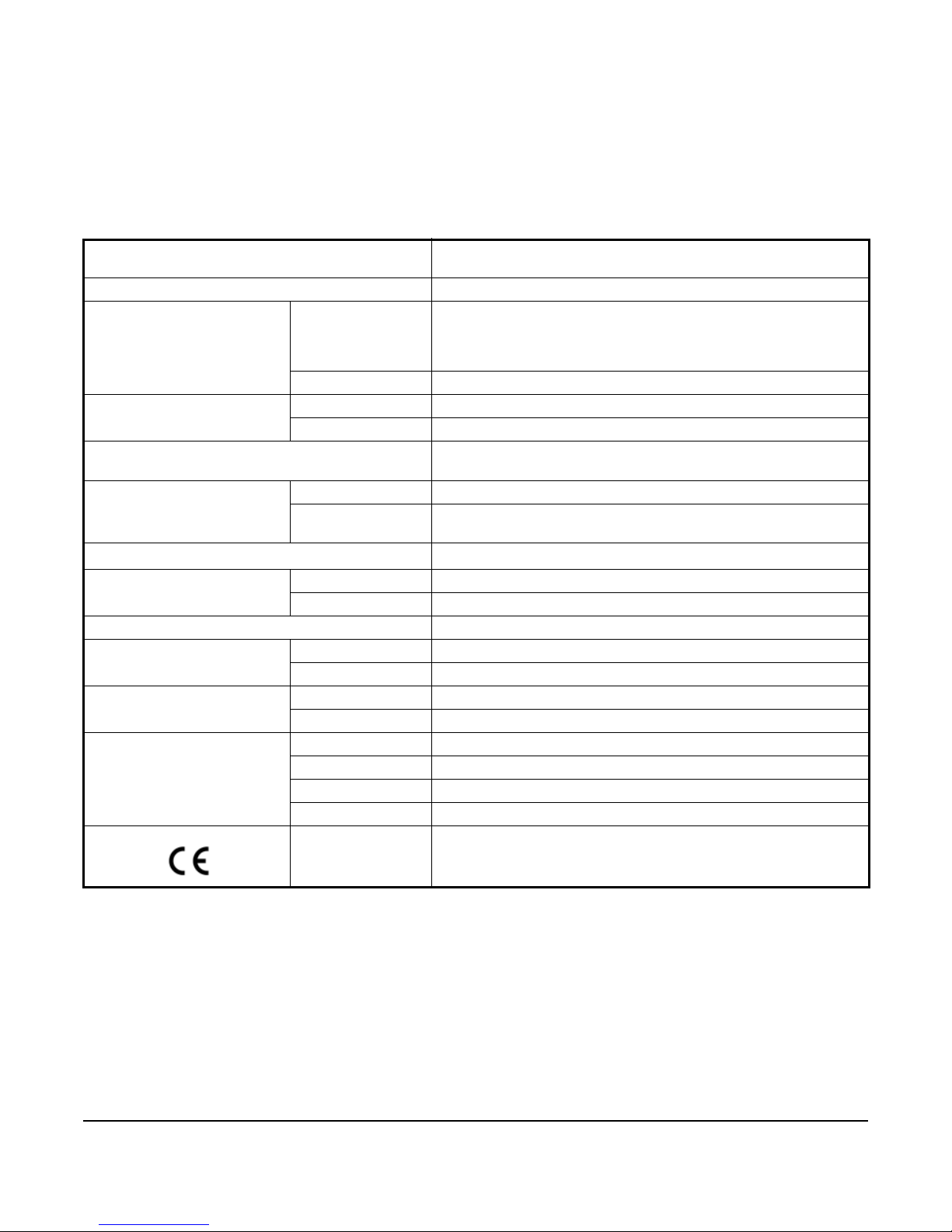
Technical Specifications
VG1000 Series Flanged Ball Valves
Service
Valve Fluid T e mpe r atu re Limits 0 to 284°F (-18 to 140°C)
Valve Body Pressure/
Temperature Rating
Maximum Closeoff Pressure Two-Way 100 psi (689 kPa)
Maximum Recommended Operating Pressure
Drop
Flow Characteristics Two-Way Equal Percentage
Rangeability
Leakage Two- or Three-Way 0.01% of maximum flow, control port, ANSI/FCI 70-2, Class 4
End Connections ASME Class 150 Flange
Minimum Ambient Operating
Temperature
Maximum Ambient
Operating Temperature
Materials Body Brass
Compliance
1
Water ASME Class 150
Steam 25 psig (172 kPa) saturated steam for HVAC systems
Three-Way 50 psi (345 kPa)
Three-Way Equal Percentage Flow Characteristics of In-line Port or
2
Three-Way 1% of maximum flow, bypass port
-4°F (-20°C) M9124 Series Non-Spring Return Actuators
-40°F (-40°C) M9220 Series Spring Return Actuators
3
122°F (50°C) M9124 Series Non-Spring Return Actuators
131°F (55°C) M9220 Series Spring Return Actuators
Flanges Ductile Iron
Ball 300 Series Stainless Steel
Stem 300 Series Stainless Steel
Europe CE Mark - Johnson Controls, Inc. declares that this product is in
Hot water, chilled water, 50/50 Glycol solutions, and 25 psig
(172 kPa) saturated steam for HVAC systems
250 psi at -20 to 100°F (-29 to 38°C)
235 psi at: 200°F (93°C)
218 psi at: 284°F (140°C)
30 psi (207 kPa) for quiet service
Linear Percentage Flow Characteristics of Angle Port
Greater than 500:1
compliance with the essential requirements and other relevant
provisions of the Pressure Equipment Directive (PED).
1. Refer to VDI 2035 Guideline for proper water treatment.
2. Rangeability is defined as the ratio of maximum controllable flow to minimum controllable flow.
3. In steam applications, install the valve with the stem horizontal to the piping, and wrap the valve and piping with insulation.
The performance specifications are nominal and conform to acceptable industry standards. For application at conditions beyond these
specifications, consult the local Johnson Controls office. Johnson Controls, Inc. shall not be liable for damages resulting from misapplication or
misuse of its products.
VG1000 Series Flanged Ball Valves Installation Instructions
8
Page 9

Metasys® and Johnson Controls® are registered trademarks of Johnson Controls, Inc.
All other marks herein are the marks of their respective owners. © 2016 Johnson Controls, Inc.
Building Efficiency
507 E. Michigan Street, Milwaukee, WI 53202
European Single Point of Contact: NA/SA Single Point of Contact: AP AC Single Point of Contact:
JOHNSON CONTROLS
WESTENDHOF 3
45143 ESSEN
GERMANY
JOHNSON CONTROLS
507 E MICHIGAN ST
MIL WAUKEE WI 53202
USA
JOHNSON CONTROLS
C/O CONTROLS PRODUCT MANAGEMENT
NO. 22 BLOCK D NEW DISTRICT
WUXI JIANGSU PROVINCE 214142
CHINA
VG1000 Series Flanged Ball Valves Installation Instructions
Published in U.S.A. www.johnsoncontrols.com
9
 Loading...