

Page 1
Product Bulletin VF Series Butterfly Valves
Issue Date August 15, 2014
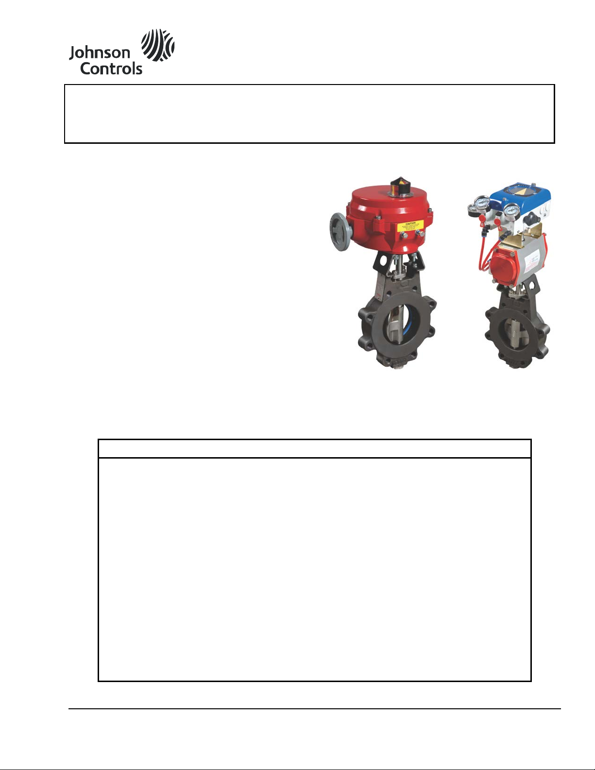
VF Series High-Pressure,
High-Temperature Butterfly Valve Assemblies
VF Series High-Press ur e, High-T e mp er ature But ter fly
Valve Assemblies are specifically designed for a wide
range of Heating, Ventilating, and Air Conditioning
(HVAC) applications including two-position and
modulating/throttling control of hot water, chilled water,
condenser water, and steam. Refer to the VF Ser i es
High-Pressure, High-Temperature Butter f l y Valves for
Steam Service Application Note (LIT-977321) for more
information on steam app lic atio ns . T hese lu g-style
valves offer bidirectional shutoff at fully rated American
National Standards Institute (ANSI) Class 150 and 300
operating pressures, increasing the range of
applications – particularly in high-rise building HVAC
control applications. ANSI Class 150 and 300 models
are also suitable for steam applications.
ANSI Class 150 Butterfly Valves are avai lab le in
two-way configurations, in sizes ranging from
2-1/2 through 16 in. ANSI Class 300 Butterfly Valves
are available in two-way configurations , in sizes
ranging from 2-1/2 through 14 in. ANSI Class 150
valves are rated for 240 psig at 250°F, and ANSI
Class 300 valves are rated for 550 psig at 250°F.
Features and Benefits
Compatible with All Types of ANSI
150/300 Slip-On and Weld-Neck Flanges
High-Pressure, High-Temperature Design
Bidirectional Shutoff, Dead-End Service Provides positive closure in both directions to
Live-Loaded Seat Design with Fully
Encased O-Ring
Double Offset Stem Design Reduces seat wear to significantly extend
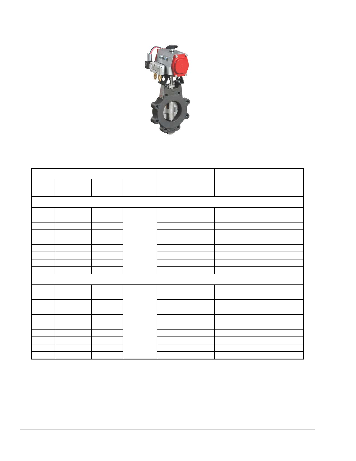
Figure 1: VF Series High-Pressure,
High-Temperature Butterfly Valve Assemblies
Enables field configuration with readily
available standard fittings
Increases the range of applications,
particularly in high-rise building HVAC control
applications
full ANSI pressure ratings
Offers superior sealing and long service life
cycle life
Broad Range of Compact Pre-Assembled
Actuators Available
Provides a wide selection for new and
replacement electric and pneumatic actuators
Direct Actuator-to-Stem Mounting Reduces hysteresis and simplifies installation
© 2014 Johnson Controls, Inc. 1
Code No. LIT-977208 www.johnsoncontrols.com
Page 2
Table 1: Ordering Data
C = Two
M = Manually Operated
N = Two
025 = 2
030 = 3 in.
040 = 4 in.
050 = 5 in.
060 = 6 in.
080 = 8 in.
100 = 10 in.
120 = 12 in.
140 = 14 in.
160 = 16 in.
V = ANSI Class 150
Z = ANSI Class 300
E = 17
See
11
B = High Pressure Positioner
C = 120 VAC Solenoid with Speed Controls
D = Thermostat/Heater Kit for On/Off
E = 24 VAC Solenoid with Speed Controls
G = Gear-Operated Manual Hand Wheel
M = Ten
N = Thermostat/Heater Kit for Proportional
Example: Two
in.,
ANSI
stem, proportional non
actuator, and thermostat/heater kit.
V F
Butterfly
1 2
C
3
– 1 0 0
4 5 6 7
V
8
E
9
Valve
Body Type
Valve Size
Flange
Stem
Material
-Way, Normally Closed (N.C.)
-Way, Normally Open (N.O.)
-1/2 in.
-4 PH Stainless Steel
– 7 0 7
10
1 2 3 4 5 6 7 8 9 10 11 12 13 14 = Field
V F C
–
1 0 0 V E
Butterfly Valve Assembly
–
7 0 7
12 13
Actuator
Accessories
N
14
N
Table 2.
Electric Actuators
-Position Manual Handle
Electric Actuators
-way normally closed valve, 10
Class 150 with 17-4 PH stainless steel
-spring return electric
2 VF Series High-Pressure, High-Tem perat ure Butt er f l y Valves Product Bulle tin
Page 3

707
=
VA-9077-01
432
=
V-9194-23
=
724
=
VA-9075-02
550
=
V-9195-15
080 = V-9098-1
Table 2: Ordering Data – Adding a Factory-Mounted Industrial-Grade
Pneumatic or Electric Actuator
Note: See Table 3, Table 4, Table 5, and Table 6 for valid factory assemblies.
Electric, Proportional, Non-Spring Return High Pressure Pneumatic, Spring Return
702 = VA-9072-01 340 = V-9193-14
703 = VA-9075-01 360 = V-9193-16
704 = VA-9075-01
705 = VA-9075-01 422 = V-9194-22
706 = VA-9076-01 430 = V-9194-13
702N4 = VA-9072-11
705N4 = VA-9075-11 440 = V-9194-14
707N4 = VA-9077-11 442 = V-9194-24
907 = VA-907A-01 452 = V-9194-25
908 = VA-907B-01
Electric, On/Off, Non-Spring Return
722 = VA-9072-02
723 = VA-9075-02 530 = V-9195-13
462
V-9194-26
725 = VA-9075-02
726 = VA-9076-02 630 = V-9196-13
727 = VA-9077-02 650 = V-9196-15
722N4 = VA-9072-12 660 = V-9196-16
725N4 = VA-9075-12
727N4 = VA-9077-12 730 = V-9197-13
750 = V-9197-15
927 = VA-907A -02
928 = VA-907B -02
High Pressure Pneumatic,
Non-Spring Return
030 = V-9093-1 820 = V-9198-12
040 = V-9094-1 830 = V-9198-13
042 = V-9094-2 840 = V-9198-14
050 = V-9095-1 850 = V-9198-15
060 = V-9096-1
070 = V-9097-1
VF Series High-Press ur e, High-Temperature Butterfly Valves Product Bulletin 3
Page 4
3
185
123
VFC-030ZE-722D
VFC-030ZE-702N
VFC-030ZE-722D4
VFC-030ZE-702N4
4
375
250
VFC-040ZE-723D
VFC-040ZE-703N
VFC-040ZE-725D4
VFC-040ZE-705N4
5
790
360
VFC-050ZE-725D
VFC-050ZE-705N
VFC-050ZE-725D4
VFC-050ZE-705N4
6
1,000
530
VFC-060ZE-726D
VFC-060ZE-706N
VFC-060ZE-727D4
VFC-060ZE-707N4
8
2,000
950
VFC-080ZE-727D
VFC-080ZE-707N
VFC-080ZE-727D4
VFC-080ZE-707N4
10
2,650
1,025
VFC-100ZE-927D
VFC-100ZE-907N
–––
–––
12
4,000
1,690
VFC-120ZE-927D
VFC-120ZE-907N
–––
–––
14
4,100
1,770
VFC-140ZE-928D
VFC-140ZE-908N
–––
–––
Two-Way, Normally Closed – ANSI Class 150 Flanges
3
2-1/2
160
78
VFC-025VE-722D
VFC-025VE-702N
VFC-025VE-722D4
VFC-025VE-702N4
3
185
123
VFC-030VE-722D
VFC-030VE-702N
VFC-030VE-722D4
VFC-030VE-702N4
4
375
250
VFC-040VE-722D
VFC-040VE-702N
VFC-040VE-722D4
VFC-040VE-702N4
5
790
360
VFC-050VE-724D
VFC-050VE-704N
VFC-050VE-725D4
VFC-050VE-705N4
6
1,350
510
VFC-060VE-725D
VFC-060VE-705N
VFC-060VE-725D4
VFC-060VE-705N4
8
2,800
1,060
VFC-080VE-725D
VFC-080VE-705N
VFC-080VE-725D4
VFC-080VE-705N4
10
4,300
1,630
VFC-100VE-726D
VFC-100VE-706N
VFC-100VE-727D4
VFC-100VE-707N4
12
6,650
2,530
VFC-120VE-727D
VFC-120VE-707N
–––
–––
14
7,650
2,900
VFC-140VE-927D
VFC-140VE-907N
–––
–––
16
9,800
3,170
VFC-160VE-927D
VFC-160VE-907N
–––
–––
1.
2.
3
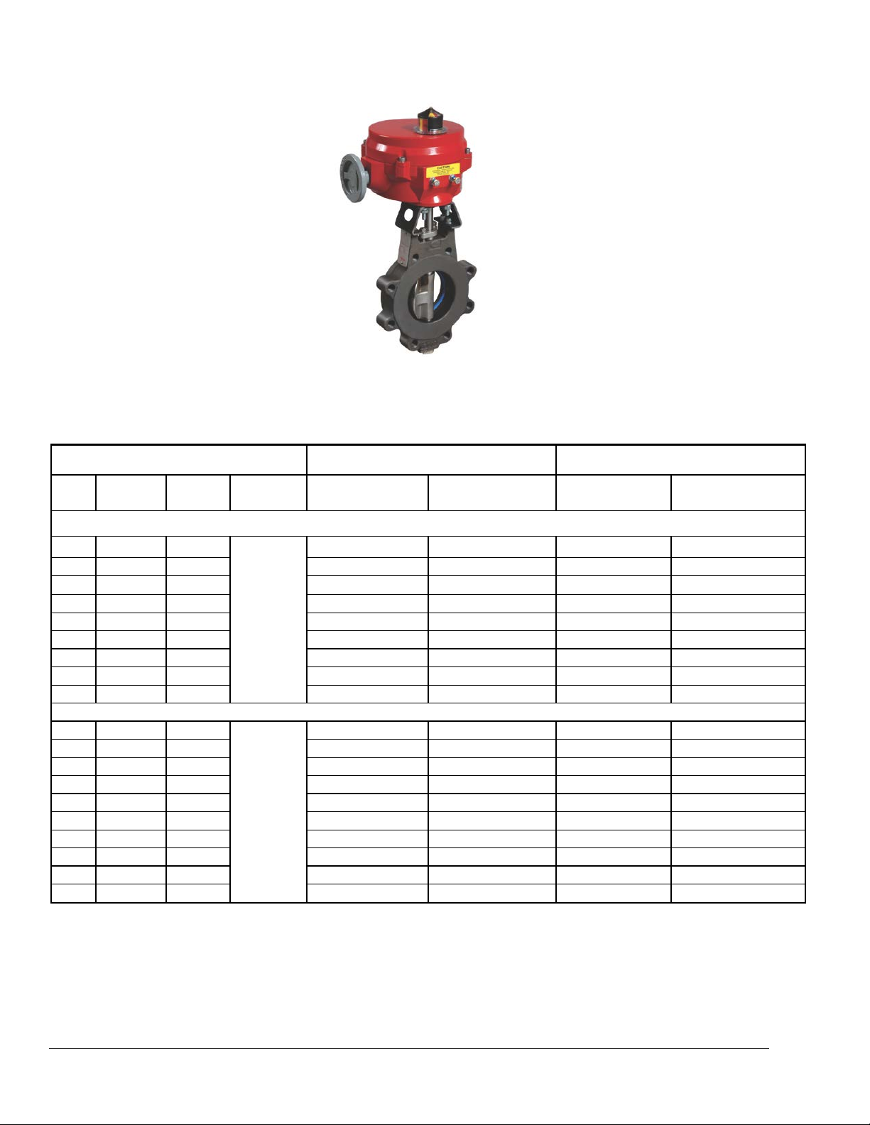
Figure 2: Two-Way Valve with Industrial-Grade,
Non-Spring Return, VA-907X Series Electric Actuator
Table 3: Two-Way Valves with Indust rial-Grade, Non-Spring Return,
VA-907X Series Electric Actuators
Actuator
AC 120 V Powered Actuator AC 24 V Powered Actuator
Size,
2-1/2 160 78
in.
Cv at 90
Degrees
Cv at 60
Degrees
Closeoff
Pressure
1
On/Off
0 to 10 VDC
Proportional
Two-Way, Normally Closed – ANSI Class 300 Flanges
VFC-025ZE-722D VFC-025ZE-702N VFC-025ZE-722D4 VFC-025ZE-702N4
550 psig
240 psig
On/Off
2
0 to 10 VDC
Proportional
Close-off pressures are dimensioned for a valve seat retainer that is oriented upstr ea m.
Maximum closeoff pressure for ANSI Class 300 valves is 740 psig (5102.1 kPa) for fluid temperatures below 100°F (37.8°C),
and 550 psig (3,790 kPa) for fluid temperatures at 250°F (121.1°C). Maximum steam pressure is 150 psig (1034.2 kPa) for
On/Off service, and 50 psig (344.8 kPa) for proportional service.
. Maximum closeoff pressure for ANSI Class 150 valves is 285 psig (1965 kPa) for fluid temperatures below 100°F (37.8°C), and
240 psig (1654.8 kPa) for fluid temperatures at 250°F (121.1°C). Maximum steam pressure is 150 psig (1034.2 kPa) for On/Off
service, and 50 psig (344.8 kPa) for proportional service.
4 VF Series High-Pressure, High-Tem perat ure Butt er f l y Valves Product Bulle tin
Page 5
2-1/2
160
78
VFC-024ZE-432C
VFN-025ZE-422C
VFC-025ZE-432B
VFN-025ZE-422B
3
185
123
VFC-030ZE-442C
VFN-030ZE-422C
VFC-030ZE-442B
VFN-030ZE-422B
4
375
250
VFC-040ZE-452C
VFN-040ZE-432C
VFC-040ZE-452B
VFN-040ZE-432B
5
790
360
VFC-050ZE-650C
VFN-050ZE-630C
VFC-050ZE-650B
VFN-050ZE-630B
6
1,000
530
VFC-060ZE-660C
VFN-060ZE-630C
VFC-060ZE-660B
VFN-060ZE-630B
8
2,000
950
VFC-080ZE-750C
VFN-080ZE-730C
VFC-080ZE-750B
VFN-080ZE-730B
10
2,650
1,200
VFC-100ZE-840C
VFN-100ZE-830C
VFC-100ZE-840B
VFN-100ZE-830B
12
4,000
1,450
VFC-120ZE-850C
VFN-120ZE-840C
VFC-120ZE-850B
VFN-120ZE-840B
2-1/2
160
78
VFC-025VE-360C
VFN-025VE-340C
VFC-025VE-360B
VFN-025VE-340B
3
185
123
VFC-030VE-360C
VFN-030VE-340C
VFC-030VE-360B
VFN-030VE-340B
4
375
250
VFC-040VE-430C
VFN-040VE-440C
VFC-040VE-430B
VFN-040VE-440B
5
790
360
VFC-050VE-462C
VFN-050VE-530C
VFC-050VE-462B
VFN-050VE-530B
6
1,350
510
VFC-060VE-550C
VFN-060VE-530C
VFC-060VE-550B
VFN-060VE-530B
8
2,800
1,060
VFC-080VE-650C
VFN-080VE-630C
VFC-080VE-650B
VFN-080VE-630B
10
4,300
1,630
VFC-100VE-750C
VFN-100VE-730C
VFC-100VE-750B
VFN-100VE-730B
12
6,650
2,530
VFC-120VE-830C
VFN-120VE-820C
VFC-120VE-830B
VFN-120VE-820B
14
7,650
2, 900
VFC-140VE-850C
VFN-140VE-830C
VFC-140VE-850B
VFN-140VE-830B
1.
2.
3.
4.
psig (1034.2 kPa) for On/Off service, and 50 psig (344.8 kPa) for proportional service.
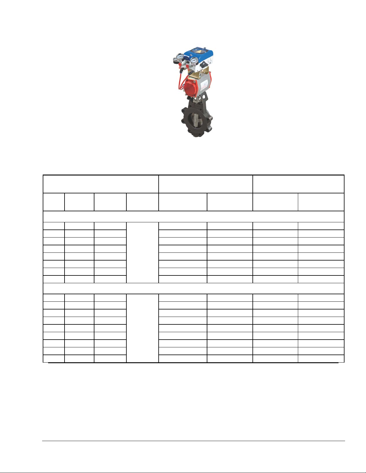
Figure 3: Two-Way Valve with Industrial-Grade,
Spring Return, V-919x Series High Pressure Pneumatic Actuator
Table 4: Two-Way Valves with Indust rial-Grade, Spring Return, V-919x Series High Pressure Pneumatic
Actuators
Actuator On/Off
1
Proportional
(with Positioner)
Size,
in.
Cv at 90
Degrees
Cv at 60
Degrees
Closeoff
Pressure
Spring Closed Spring Open Spring Closed Spring Open
2
Two-Way, Normally Closed – ANSI Class 300 Flanges3
550 psig
Two-Way, Normally Closed – ANSI Class 150 Flanges4
240 psig
On/Off assemblies come with 120 VAC solenoid valve and speed controls. If a 24 VAC solenoid is desired, change
the C at the end of the code number to an E.
Close-off pressures are dimensioned for a valve seat retainer that is oriented upstream.
Maximum closeoff pressure for ANSI Class 300 valves is 740 psig (5102.1 kPa) for fluid temperatures below 100°F
(37.8°C), and 550 psig (3,790 kPa) for fluid temperatur es at 250° F (121.1°C). Maximum steam pressure is 150 psig
(1034.2 kPa) for On/Off service, and 50 psig (344.8 kPa) for proportional service.
Maximum closeoff pressure for ANSI Class 150 valves is 285 psig (1965 kPa) for fluid temperatures below 100°F
(37.8°C), and 240 psig (1654.8 kPa) for fluid temperatures at 250°F (121.1°C). Maximum steam pressure is 150
VF Series High-Press ur e, High-Temperature Butterfly Valves Product Bulletin 5
Page 6
2-1/2
160
78
VFC-025ZE-030C
VFC-025ZE-030B
3
185
123
VFC-030ZE-030C
VFC-030ZE-030B
4
375
250
VFC-040ZE-040C
VFC-040ZE-040B
5
790
360
VFC-050ZE-042C
VFC-050ZE-042B
6
1,000
530
VFC-060ZE-050C
VFC-060ZE-050B
8
2,000
950
VFC-080ZE-060C
VFC-080ZE-060B
10
2,650
1,025
VFC-100ZE-070C
VFC-100ZE-070B
12
4,000
1,690
VFC-120ZE-070C
VFC-120ZE-070B
14
4,100
1,770
VFC-140ZE-080C
VFC-140ZE-080B
2-1/2
160
78
VFC-025VE-030C
VFC-025VE-030B
3
185
123
VFC-030VE-030C
VFC-030VE-030B
4
375
250
VFC-040VE-030C
VFC-040VE-030B
5
790
360
VFC-050VE-042C
VFC-050VE-042B
6
1,350
510
VFC-060VE-042C
VFC-060VE-042B
8
2,800
1,060
VFC-080VE-050C
VFC-080VE-050B
10
4,300
1,630
VFC-100VE-060C
VFC-100VE-060B
12
6,650
2,530
VFC-120VE-070C
VFC-120VE-070B
14
7,650
2,900
VFC-140VE-070C
VFC-140VE-070B
16
9,800
3,170
VFC-160VE-080C
VFC-160VE-080B
Figure 4: Two-Way Valve with Industrial-Grade, Non-Spring Return, V-909x Series High Pressure
Pneumatic Actuator
Table 5: Two-Way Valves with Indust rial-Grade, Non-Spring Return,V-909x Series High Pressure
Pneumatic Actuators
Actuator
Size,
in.
Cv at 90
Degrees
Cv at 60
Degrees
Closeoff
Pressure
1
2
On/Off
Proportional
(with Positioner)
Two-Way, Normally Closed – ANSI Class 300 Flanges3
550 psig
Two-Way, Normally Closed – ANSI Class 150 Flanges4
240 psig
1. On/Off assemblies come with 120 VAC solenoid valve and speed controls. If a 24 VAC solenoid is desired,
change the C at the end of the code number to an E.
2. Close-off pressures are dimensioned for a valve seat retainer that is oriented upstream.
3. Maximum closeoff pressure for ANSI Class 300 valves is 740 psig (5102.1 kPa) for fluid temperatures below 100°F
(37.8°C), and 550 psig (3,790 kPa) for fluid temperatur es at 250° F (121.1°C). Maximum steam pressure is 150 psig
(1034.2 kPa) for On/Off service, and 50 psig (344.8 kPa) for proportional service.
4. Maximum closeoff pressure for ANSI Class 150 valves is 285 psig (1965 kPa) for fluid temperatures below 100°F
(37.8°C), and 240 psig (1654.8 kPa) for fluid temperatures at 250°F (121.1°C). Maximum steam pressure is 150 psig
(1034.2 kPa) for On/Off service, and 50 psig (344.8 kPa) for proportional service.
6 VF Series High-Pressure, High-Tem perat ure Butt er f l y Valves Product Bulle tin
Page 7
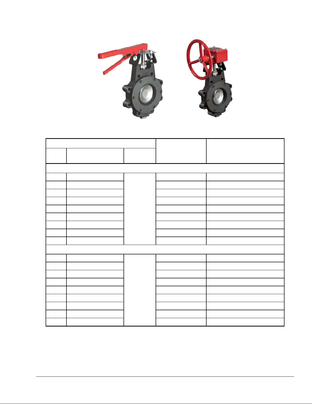
Figure 5: Two-Way Valve with Manual Operator
2-1/2
4
375
VFM-040ZE-000M
VFM-040ZE-000G
5
8
10
14
2-1/2
5
8
2,800
---
VFM-080VE-000G
10
14
Table 6: Two-Way Valves with Manual Operato rs
Actuator
Size,
in.
Cv at 90 Degrees
Closeoff
Pressure
1
Two-Way, Manually Operated – ANSI Class 300 Flanges2
Ten-Position
Manual Handle
Manual Hand Wheel
Gear-Operated
160
3 185 VFM-030ZE-000M VFM-030ZE-000G
790
6 1,000 VFM-060ZE-000M VFM-060ZE-000G
2,000 --- VFM-080ZE-000G
2,650 --- VFM-100ZE-000G
12 4,000 --- VFM-120ZE-000G
4,100 --- VFM-140ZE-000G
550 psig
VFM-025ZE-000M VFM-025ZE-000G
VFM-050ZE-000M VFM-050ZE-000G
Two-Way, Manually Operated – ANSI Class 150 Flanges3
160
3 185
4 375 VFM-040VE-000M VFM-040VE-000G
790 VFM-050VE-000M VFM-050VE-000G
6 1,350 VFM-060VE-000M VFM-060VE-000G
4,300
12 6,650 --- VFM-120VE-000G
7,650 --- VFM-140VE-000G
1. Close-off pressures are dimensioned for a valve seat retainer that is oriented upstream.
2. Maximum closeoff pressure for ANSI Class 300 valves is 740 psig (5102.1 kPa) for fluid temperatures below 100°F
(37.8°C), and 550 psig (3,790 kPa) for fluid temperatur es at 250° F (121.1°C). Maximum steam pressure is 150 psig
(1034.2 kPa) for On/Off servi c e, and 50 psig (344. 8 kPa) for proportional service.
3. Maximum closeoff pressure for ANSI Class 150 valves is 285 psig (1965 kPa) for fluid temperatures below 100°F
(37.8°C), and 240 psig (1654.8 kPa) for fluid temperatures at 250°F (121.1°C). Maximum steam pressure is 150 psig
(1034.2 kPa) for On/Off service, and 50 psig (344.8 kPa) for proportional service.
240 psig
VFM-025VE-000M VFM-025VE-000G
VFM-030VE-000M VFM-030VE-000G
--- VFM-100VE-000G
VF Series High-Press ur e, High-Temperature Butterfly Valves Product Bulletin 7
Page 8
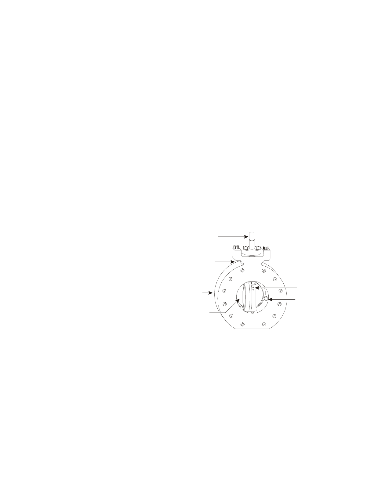
Application Overview
Stem
Extended
Neck
Valve
Body
Disc
Taper Pin s
Internal Travel Stop
VF Series High-Press ur e, High-Temperature Butterfly
Valves provide the highest quality and best value
available in the HVAC control industry. These valves
are recognized as a proven leader, with more than
25 years of successful service in process industries
worldwide. Their unique, patented design has received
Chemical Processing’s Valor Award for Best Product.
The simple, innovative design of these valves provides
rugged reliability and extremely easy maintenance in
the field. Independent and internal tests have proven
their superior service life capability, with bubble-tight
shutoff through over 100,000 cycles.
VF Series High-Pr ess ur e, High-Temperature Butterfly
Valves can be automated inexpensively with
pneumatic and electric actuators.
When compared to gate, globe, ball, and plug valves,
VF Series High-Press ur e, High-Temperature Butterfly
Valves are significantly smaller and lighter in weight;
therefore, installation time and maintenance costs are
greatly reduced.
All VF Series High-Pressure, High-Temperature
Butterfly Valves are available with a factory-assembled
and calibrated actuator, sized with a 25% safety factor
to provide years of trouble-free operation. The wide
variety of actuator choices include high-pressure
pneumatic rack and pinion-style actuators (both spring
return and non-spring return), and high-torque rotary
electric actuators which are fully compatible with
®
Metasys
controllers. The valve and actuator can be
provided in Normally Open (N.O.) or Normally
Closed (N.C.) combinations for pneumatic two-way
operation.
Stem
The one-piece stem is constructed of high strength
17-4 PH stainless steel. The output shaft of the stem is
extended to provide a direct connection of the actuator
to the valve.
Disc
The disc is constructed of 316 stainless steel, and is
engineered to maximize flow. The double offset design
of the stem reduces seat wear to significantly extend
cycle life. Bidirectional bubble-tight shutoff is assured
throughout the full pressure range.
Taper Pins
The taper pins are precision fit into drilled,
taper-reamed holes, providing a positive connection
and maximum strength between the valve disc and
stem.
Internal Travel Stop
An internal travel stop is designed to prevent
overtravel of the disc, minimizing possible seat
damage.
Valve Body
The ANSI Class 150 lug-style valve body is carbon
steel, and meets the pressure and temperature
requirements for ANSI B16.5, Class 150 pipe flanges.
The ANSI Class 300 lug-style valve body is carbon
steel, and meets the pressure and temperature
requirements for ANSI B16.5, Class 300 pipe flanges.
Figure 6: VF Series High-Pressure,
High-Temperature Butterfly Valve
Extended Neck
The extended neck allows for 2 in. (51 mm) of pipeline
insulation, as well as easy access for stem packing
adjustments and actuator mounting.
8 VF Series High-Pressure, High-Tem perat ure Butt er f l y Valves Product Bulle tin
Page 9
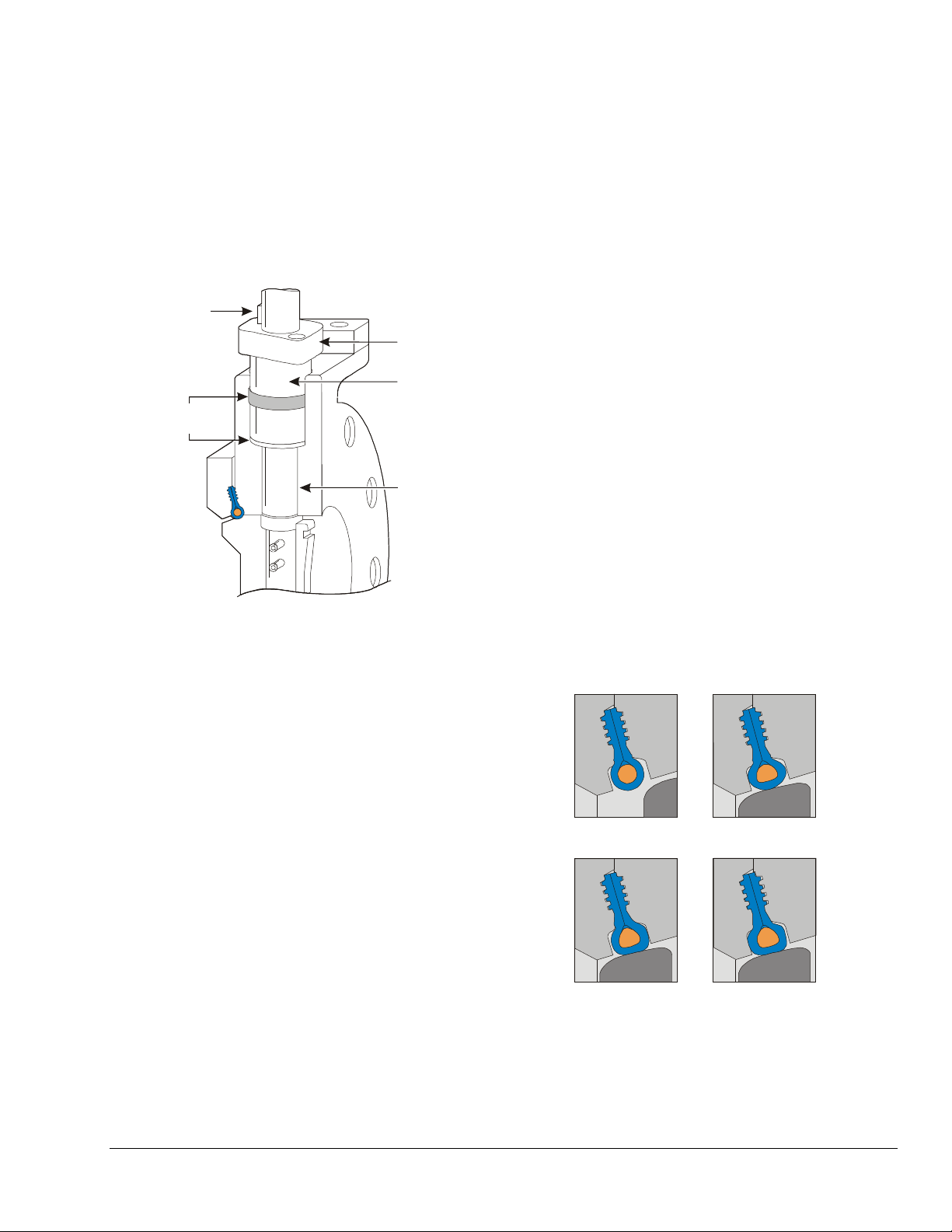
Gland
Retainer
Gland
Ring
Stem Bearings
Stem
Seal
Studs,
Hex-Head
Nuts, and
Lock
Washers
Seat non-compressed
as disc approaches.
Disc in c losed p os ition;
with no line pressure.
Disc in c losed p os ition;
line pressure applie d
from the left.
Disc in c losed p os ition;
line pressure applie d
from the right.
Adjustable Stem Packing
The stem packing system features easy access to
adjusting hex-head nuts wit hout re qu irin g removal of
the actuator. The stem consists of a gland ring, a
gland retainer, studs, hex-head nuts, and lock
washers. A slight 1/4 turn of the hex-head nuts is
usually all that is required should field adjustment ever
be needed. Both hex-head nuts must be evenly
adjusted, and not over tightened.
Figure 7: Adjustable Stem Packing System
Stem Seal
A positive seal is formed around the stem by the
constant compression and excellent corrosion
resistance of the stem seal. PTFE packing rings seal
the stem, and a carbon fiber anti-extrusion ring retains
the packing.
Seat Design
The unique, live-loaded seat consists of a resilient
silicone O-ring energizer that is fully encased by the
reinforced polytetrafluoroethylene (RPTFE) seat. The
seat is locked into the valve body recess by a
full-faced seat retainer plate. This simple, reliable, and
proven combination provides many exclusive
advantages including:
• The O-ring energizer is completely isolated from
all contact with the line media by the RPTFE seat.
• Serrations in the seat retainer plate and body
recess secure the seat in place. The full-faced
retainer plate is bolted to the body, locking the
seat in the correct position. The seat is secured
even without the mating flange.
• The closely confined and well supported seat is
energized by the disc and line pressure. The
higher the pressure, the tighter the seal. In low
pressure applications, the energized seat offers
superior sealing and longer service life than many
other designs.
• Line media is sealed bubble-tight in both
directions.
• The live-loaded seat is self adjusting for wear and
temperature fluctuations.
• Seat replacement is extremely easy – just remove
the seat retainer plate, rotate the disc into the
closed position, and place a new seat in the
machined recess of the body. Performing this
procedure does not disturb the disc or stem.
All ANSI Class 150 and 2-1/2 through 12 in.
ANSI Class 300 valves feature one set of stem seal
packing rings and a stem locating plug with an O-ring
seal in the body base. The 14 in. ANSI Class 300
valves feature upper and base twin stem seals that
balance axial forces on the stem and disc under all
operating conditions.
Stem Bearings
Top and bottom bearings, consisting of a
316 stainless steel shell with a TFE/glass fabric liner
bearing surface, securely support the stem. The stem
bearings provide excellent resistance to corrosion and
distortion from high temperatures and mechanical
loading forces.
Figure 8: Exclusive High Performance Seat
VF Series High-Press ur e, High-Temperature Butterfly Valves Product Bulletin 9
Page 10

Double Offset Stem and Disc Design
Disc in the
Open Position
Disc in the
Closed Position
Stem
Seat
Body
Temperature °C
Pr essur e psig
Press ure Bar
Tem perat ure °F
350
0
100
200
250
300
250
200
150
100
50
20
15
10
5
-20
0 100
200
300 400 500
Temperature °C
Pressure psig
Press ure B ar
Tem perat ure °F
800
0 100 200 250
700
600
500
400
300
200
100
50
40
30
20
10
-20
0
100 200 300 400 500
The double offset design of VF Series High-Pressure,
High-Temperature Butterfly Valves ensures reduced
seat wear and bidirectional bubble-tight shutoff
throughout the full pressure range.
At the point of initial disc opening, the offset disc
produces a cam-like action that rotates the disc away
from the seat with minimum drag. This
cam-like action reduces seat wear and eliminates seat
deformation when the disc is in the open position.
When the disc rotates beyond the point of initial
opening, the disc does not make contact with the seat.
This superior design extends the seat service life and
reduces the valve operating torque. As the valve
closes, the cam-like action converts the rotary motion
to effectively push the disc onto the seat. The wip ing
action of the disc against the seat prevents
undesirable material buildup from suspended solids.
The taper pins carry essentially equal loads while
anchoring the disc to the stem. This arrangement
permits accurate disc closure for consistent sealing
and positive shutoff.
For more than 25 years, the reliability of these butterfly
valves has been conclusively proven, both in lab tests
as well as thousands of field applications. In one test
of over 100,000 cycles at 720 psig (4,961 kPa) of
pressure, the seat remained in excellent condition and
continued to provide a bidirection al bub bl e-tight seal.
In another test of more than 878,000 cycles at 2 psig
(14 kPa) of pressure, the ANSI Class 150 valve
continued to seal bubble-tight in both directions.
Figure 10: ANSI Class 150
VF Series High-Pressure, High-Temperature
Butterfly Valves
Pressure/Temperature Ratings
Figure 9: Double Offset Stem and Disc
Figure 11: ANSI Class 300
VF Series High-Pressu r e, Hig h-Temperature
Butterfly Valves
Pressure/Temperature Ratings
10 VF Series High-Pressure, High-Temperature Butterfly Valves Product Bulletin
Page 11

2-1/2
3
5
6
10
16
Table 7: Rangeability Values for 90° Rotation1
Valve Size,
in.
4 30:1 30:1
8 43:1 43:1
12 43:1 43:1
14 43:1 43:1
1. For steam throttling service applications, refer to the VF Series High-Pressure, High-Temperature Butterfly Valves
for Steam Service Application Note (LIT-977321).
ANSI Class 150 Valves ANSI Class 300 Valves
30:1 30:1
30:1 30:1
39:1 39:1
39:1 39:1
43:1 43:1
43:1 ---
90° Disc Rotation
Valve Actuators
All VF Series High-Pressure, High-Temperature
Butterfly Valves are available with a wide range of
factory-installed pneumatic and electric actuators.
Table 8 and Table 9 list the actuator choices available
for each ANSI Class valve type. All valve and actuator
combinations have been sized with torque safety
factors to provide adequate actuator torque for years
of trouble-free operation.
Optional Actuator Accessories
All V-909x and V-919x Series High Pressure
Pneumatic Rack and Pinion Actuators are furnished
with factory installed 120 VAC solenoid valves for
two-position operation. When these actuators are used
for proportional service, the solenoid valve is replaced
with a high pressure positioner. In two-position
applications, factory-installed speed controls are
available as a selec tab le o ptio n.
For more details on additional actuator accessories,
refer to the appropriate actuator product bulletin.
VF Series High-Press ur e, High-Temperature Butterfly Valves Product Bulletin 11
Page 12

2-1/2
3
5
6
10
16
2-1/2
4
8
14
Table 8: Representative Maximum Shipping Weights for VF Series High-Pressure,
High-Temperature ANSI Class 150 Butterfly Valve a n d Actu ato r Assembli es
Valve Size,
in.
4 V-9194-13 (430) 56 (25.4)
8 V-9196-15 (650) 165 (74.9)
12 V-9198-13 (830) 389 (177.6)
14 V-9198-15 (850) 482 (218.8)
1. The above shipping weights are approximate, and are based on the heaviest valve, actuator, and accessory
combination available for each assembly size.
Representative Actuator
(Actuator Sub-Code)
V-9193-16 (360) 41 (18.6)
V-9193-16 (360) 45 (20.4)
V-9195-13 (530) 80 (36.3)
V-9195-15 (550) 90 (40.9)
V-9197-15 (750) 250 (113.5)
V-9098-1 (080) 571 (259.2)
1
Shipping Weight,
lb (kg)
Table 9: Representative Maximum Shipping Weights for VF Series High-Pressure,
High-Temperature ANSI Class 300 Butt erfl y Valve and Actuator Assemblies
Valve Size,
in.
Representative Actuator
(Actuator Sub-Code)
1
Shipping Weight,
lb (kg)
VA-9072-01 (702) 42 (19.3)
3 VA-9072-01 (702) 52 (23.9)
VA-9075-01 (705) 75 (34.1)
5 V-9196-15 (650) 135 (61.3)
6 V-9196-16 (660) 155 (70.4)
V-9197-15 (750) 240 (109.0)
10 V-9198-14 (840) 386 (175.2)
12 V-9198-15 (850) 474 (215.2)
V-9098-1 (080) 621 (281.9)
1. The above shipping weights are approximate, and are based on the heaviest valve, actuator, and accessory
combination available for each assembly size.
12 VF Series High-Pressure, High-Temperature Butterfly Valves Product Bulletin
Page 13

Optional Actuator Accessories
A
C
D
B
For manually operated actuator and valve assemblies,
a ten-position manual handle or gear-operated manual
hand wheel is available. See Table 10 and Table 11
for more details.
Figure 12: Dimensions for Ten-Position Manual H andles
(See Table 10.)
Table 10: Dimensions for Ten-Position Manual Handles, in. (mm)
Valve Size,
ANSI
Class 150
Valves
in.
ANSI
Class 300
Valves
Ten-Position
Manual Handle
Kit
1
A B C D
2-1/2
through 4
5 and 6 5 VF-999-402
1. Kit includes a manual handle, notch plate, bracket, and mounting hardware.
2-1/2
through 4
VF-999-401
10.62
(270)
10.62
(270)
1.12
(28)
1.12
(28)
1.38
(35)
1.38
(35)
1.0
(25)
1.0
(25)
VF Series High-Press ur e, High-Temperature Butterfly Valves Product Bulletin 13
Page 14

A
B
C
D
E
Figure 13: Dimensions for Gear-Operated Manual Hand Wheels
(See Table 11.)
Table 11: Dimensions for Gear-Operated Manual Hand Wheels, in. (mm)
Valve Size,
ANSI
Class 150
Valves
in.
ANSI
Class 300
Valves
Gear-Operated
Manual
Hand Wheel Kit
A B C D E
1
2-1/2
through 4
5 and 6 5 VF-999-502
8 6 VF-999-503
10 8 VF-999-504
12 --- VF-999-505
14 and 16 --- VF-999-506
--- 10 VF-999-507
--- 12 VF-999-508
--- 14 VF-999-509
1. Kit includes a manual hand wheel, bracket, adaptor (if required), and mounting hardware.
2-1/2
through 4
VF-999-501
6.89
(175)
6.89
(175)
6.89
(175)
6.89
(175)
6.89
(175)
10.51
(267)
10.51
(267)
10.51
(267)
10.51
(267)
5.91
(150)
5.91
(150)
5.91
(150)
5.91
(150)
5.91
(150)
8.27
(210)
8.27
(210)
8.27
(210)
8.27
(210)
7.50
(191)
7.50
(191)
7.50
(191)
7.69
(195)
7.69
(195)
14.88
(378)
14.81
(376)
14.81
(376)
14.88
(378)
8.0
(203)
8.0
(203)
8.0
(203)
12.0
(305)
12.0
(305)
18.0
(457)
12.0
(305)
12.0
(305)
18.0
(457)
2.50
(64)
2.50
(64)
2.50
(64)
2.50
(64)
2.50
(64)
4.39
(112)
4.39
(112)
4.39
(112)
4.39
(112)
14 VF Series High-Pressure, High-Temperature Butterfly Valves Product Bulletin
Page 15

Product Guidelines
Please be sure to read the following information
carefully before installing a VF Series High-Pressure,
High-Temperature Butterfly Valve Assembly:
• The valve is designed to be mounted between
ANSI flanges. When the valve is open, the disc
extends into the pipe on both sides of the valve
(further on the body side than the seat retainer
side). Piping must be large enough to allow the
disc to clear the pipe. In general, Class 150 valves
clear the Schedule 40 pipe, and Class 300 va lves
clear the Schedule 80 pipe adeq uat ely.
If heavier piping is required, chamfering or
recessing of the pipe inner diameter may be
necessary. Contact the local Bray representative
for more information.
• If the handle or actuator has been removed, do not
rotate the disc beyond the fully open or closed
position; doing so could cause damage to the
sealing surfaces. VF Series High-Pressure,
High-Temperature Butterfly Valves are equipped
with stops to prevent overclosure. The valve is
opened by turning counterclockwise and closed by
turning clockwise. The machined flats at the top of
the stem are parallel to the disc. For larger
diameter valves that use a keyway, the disc
follows the orientation of the key.
• For maximum service life, install the valve with the
seat retainer upstream. Positive shutoff is obtained
with the valve in either position; however,
installation with the seat retainer upstream
provides longer service life, especially in erosive
services.
• With the disc in the closed position, carefully
center the valve between the flanges. Tapped
holes match ANSI pipe flanges and assist in
positive alignment.
• The seat is sufficiently compressed by the seat
retainer, and additional force from flange bolting is
not required.
• Gaskets must conform to the requirements of
API Standard 601, Edition 3 for ANSI B16.5 class
flanges. Spiral wound gaskets are acceptable.
VF Series High-Press ur e, High-Temperature Butterfly Valves Product Bulletin 15
Page 16

K
H
(=)
(=)
C
B
L
D
E
F
A
K
Mounting
J
G
Lug Bolt ing
Figure 14: Two-Way VF Series High-Pressure, High-Temperature
Butterfly Valve Dimensions (See Table 12 and Table 13.)
1
Table 12: ANSI Class 150 Two-Way Valve Dimensions, in.
Valve
Size, in.
2-1/2 4.75 1.88 2.28 3.81 6.38 4.36 0.63 0.43 1.25 2.50 0.77 5.50 4 5/8–11 14
3 5.25 1.88 2.86 4.09 6.63 4.36 0.63 0.43 1.25 2.50 0.77 6.00 4 5/8–11 15
4 6.75 2.03 3.72 4.71 7.50 4.36 0.63 0.43 1.25 2.50 0.75 7.50 8 5/8–11 23
5 7.50 2.23 4.80 5.07 7.50 5.12 0.75 0.51 1.25 4.50 0.94 8.50 8 3/4–10 34
6 8.62 2.23 5.88 5.57 8.00 5.12 0.75 0.51 1.25 4.50 0.94 9.50 8 3/4–10 47
8 10.75 2.40 7.80 6.94 9.50 5.12 0.87 0.63 1.25 4.50 0.94 11.75 8 3/4–10 54
10 13.06 2.75 9.78 8.56 10.75 6.12 1.18 0.87 2.00 4.50 1.07 14.25 12 7/8–9 94
12 15.50 3.08 11.74 10.18 12.25 6.12 1.18 0.87 2.00 4.50 1.13 17.00 12 7/8–9 136
14 17.50 3.73 12.90 11.95 14.50 7.75 1.38 .39x.39 2.00 6.50 1.42 18.75 12 1–8 227
16 19.81 4.11 14.68 12.94 17.75 10.38 1.97 .47x.39 2.50 6.50 1.66 21.25 16 1–8 345
1. 1 in. x 25.4 = 1 mm.
2. 1 lb x 0.454 = 1 kg (net weight for valve only – no actuator).
A B C D E F G H J K L
Lug Bolting Data
BC,
in.
No. of
Holes
Threads
UNC-2B
Net
Valve
Weight,
2
lb
16 VF Series High-Pressure, High-Temperature Butterfly Valves Product Bulletin
Page 17

6
12
3
5
2-3/4 (70)
4
3/8 (10)
8-1/2 (216)
8
3/4–10
6
10
4-29/32 (125)
4
9/16 (14)
14-1/4 (362)
12
7/8–9
12
16
Table 13: ANSI Class 300 Two-Way Valve Dimensions, in.
Valve
Size, in.
2-1/2 4.75 1.88 2.28 3.81 6.38 4.36 0.63 0.43 1.25 2.50 0.77 5.88 8 3/4–10 15
3 5.25 1.88 2.28 4.09 6.63 4.36 0.63 0.43 1.25 2.50 0.77 6.63 8 3/4–10 17
4 6.75 2.03 3.72 4.71 7.50 4.36 0.63 0.43 1.25 2.50 0.75 7.88 8 3/4–10 23
5 8.25 2.23 4.80 5.13 8.00 5.12 0.75 0.51 1.25 4.50 0.94 9.25 8 3/4–10 39
8 10.94 2.82 7.56 7.55 10.00 6.12 1.18 0.87 2.00 4.50 1.10 13.00 12 7/8–9 89
10 13.26 3.28 9.44 9.36 11.38 6.12 1.38 .39x.39 2.00 4.50 1.28 15.25 16 1–8 144
14 17.90 4.66 11.38 12.50 18.25 10.38 1.97 .47x.39 2.50 6.50 2.13 20.25 20 1-1/8–8 444
1. 1 in. x 25.4 = 1 mm.
A B C D E F G H J K L
8.88 2.42 5.75 6.25 8.75 5.12 0.87 0.63 1.25 4.50 0.97 10.62 12 3/4–10 54
15.57 3.62 11.31 10.89 13.50 7.75 1.38 .39x.39 2.00 6.50 1.40 17.75 16 1-1/8–8 217
1
Lug Bolting Data
BC,
in.
No. of
Holes
Threads
UNC-2B
2. 1 lb x 0.454 = 1 kg (net weight for valve only – no actuator).
Table 14: Two-Way ANSI Class 150 VF Series High-Pressure, High-Temperature
Butterfly Valve Actuator Mounting and Valve Lug Bolting
1
Dimensions
Actuator Mounting Valve Lug Bolting
Valve
Size,
in.
Bolt
Pattern,
in. (mm)
Number of
Holes
2
Hole
Diameter,
in. (mm)
Bolt Circle,
in. (mm)
Number of
Holes
3
Net
Valve
Weight
2
lb
Bolt Thread
UNC-2B
2-1/2 2-3/4 (70) 4 3/8 (10) 5-1/2 (140) 4 5/8–11
2-3/4 (70) 4 3/8 (10) 6 (152) 4 5/8–11
4 2-3/4 (70) 4 3/8 (10) 7-1/2 (191) 8 5/8–11
2-3/4 (70) 4 3/8 (10) 9-1/2 (241) 8 3/4–10
8 4-29/32 (125) 4 9/16 (14) 11-3/4 (298) 8 3/4–10
4-29/32 (125) 4 9/16 (14) 17 (432) 12 7/8–9
14 6-1/2 (165) 4 13/16 (21) 18-3/4 (476) 12 1–8
6-1/2 (165) 4 13/16 (21) 21-1/4 (540) 16 1–8
1. See Table 12 and Table 13 for bolting requirements.
2. Actuator mounting holes are drilled (not tapped).
3. Lug holes are drilled and tapped, and evenly spaced around the valve.
VF Series High-Press ur e, High-Temperature Butterfly Valves Product Bulletin 17
Page 18

Actuator Mounting
Valve Lug Bolting
2-1/2
2-3/4 (70)
4
3/8 (10)
5-7/8 (149)
8
3/4–10
3
2-3/4 (70)
4
3/8 (10)
6-5/8 (168)
8
3/4–10
4
2-3/4 (70)
4
3/8 (10)
7-7/8 (200)
8
3/4–10
5
2-3/4 (70)
4
3/8 (10)
9-1/4 (235)
8
3/4–10
6
4-29/32 (125)
4
9/16 (14)
10-5/8 (270)
12
3/4–10
8
4-29/32 (125)
4
9/16 (14)
13 (330)
12
7/8–9
10
4-29/32 (125)
4
9/16 (14)
15-1/4 (387)
16
1–8
12
4-29/32 (125)
4
9/16 (14)
17-3/4 (451)
16
1-1/8–8
14
6-1/2 (165)
4
13/16 (21)
20-1/4 (514)
20
1-1/8–8
5/8 (16)
2 (51)2 4 4
3/4 (19)
2-1/4 (57)2
8
5/8 (16)
2 (51)2 4 4
3/4 (19)
2-1/4 (57)2
8
5/8 (16)
5/8 (16)
1-3/4 (44)
2-1/4 (57)2
8
8
3/4 (19)
3/4 (19)
2 (51)
2-1/2 (64)2
8
8
3/4 (19)
3/4 (19)
1-3/4 (44)
2-1/4 (57)2
8
8
3/4 (19)
3/4 (19)
2-1/2 (64)
3-1/4 (82)2
12
12
3/4 (19)
2-1/4 (57)2
8
3/4 (19)
3 (76)2
12
3/4 (19)
2-1/2 (64)2
8
7/8 (22)
3-1/2 (88)2
12
7/8 (22)
7/8 (22)
2 (51)
3 (76)2
12
12
1 (25)
1 (25)
3-1/2 (88)
3-1/2 (88)2
16
16
7/8 (22)
7/8 (22)
2 (51)
3 (76)2
12
12
1-1/8 (29)
1-1/8 (29)
3-1/2 (88)
4 (102)2
16
16
1-1/8 (29)
3-1/2 (88)2
43
Table 15: Two-Way ANSI Class 300 VF Series High-Pressure, High-Temperature
Butterfly Valve Actuator Mounting and Valve Lug Bolting
1
Dimensions
Valve
Size,
in.
1. See Table 12 and Table 13 for bolting requirements.
2. Actuator mounting holes are drilled only (not tapped).
3. Lug holes are drilled and tapped, and evenly spaced around the valve.
Bolt
Pattern,
in. (mm)
Number of
Holes
2
Hole
Diameter,
in. (mm)
Bolt Circle,
in. (mm)
Number of
Holes
3
Bolt Thread
UNC-2B
Table 16: Flange Screws Required for VF Series High-Pressure, High-Temperature Butterfl y Valves
Regular Hex-Head Screws with National Course Threads
Valve
Size,
in.
2-1/2
Diameter,
in. (mm)
ANSI Class 150 Valves ANSI Class 300 Valves
5/8 (16)
Length1,
in. (mm)
1-1/2 (38)
Number
Required
Diameter,
in. (mm)
3/4 (19)
Length1,
in. (mm)
1-3/4 (44)
Number
Required
8
3
4
5
6
8
10
12
14
16
1. Bolt lengths indicated include allowances for installing 1/16 or 1/8 in. thick gasket. Refer to the flange standards
for bolting material specifications (as listed in ANSI B16.5 and American Society of Mechanical Engineers [ASME]
B16.47).
2. Install from seat retainer side of valve.
3. Install in flange bolt holes closest to the valve stem.
5/8 (16)
3/4 (19)
3/4 (19)
1 (25)
1 (25)
1 (25)
1 (25)
1-1/2 (38)
1-3/4 (44)
2 (51)
2-1/2 (64)
3-1/2 (88)
3 (76)
3-1/2 (88)
3/4 (19)
8
8
2
2
12
12
16
16
3/4 (19)
7/8 (22)
1-1/8 (29)
1-1/8 (29)
1-1/8 (29)
--- --- ---
1-3/4 (44)
2-1/4 (57)
3 (76)
4 (102)
2
4 (102)
3 (76)
8
12
12
16
16
4
3
18 VF Series High-Pressure, High-Temperature Butterfly Valves Product Bulletin
Page 19

H
G
F
E
D
C
A
B
FRONT VIEW
SIDE VIEW
3
6
10
2.75 (70)
3.28 (83)
10.75 (273)
11.38 (289)
12
16
Figure 15: Overall Dimensions, in. (mm) for Industrial-Grade V-9000 Series High Pressure
Pneumatic Actuated Two-Way VF Series High-Pressure, High-Temperature Butterfly Valves
(See Table 17 and Table 18.)
Table 17: Overall Dimensions, in. (mm) for Industrial-Grade V-9000 Series
High Pressure Pneumatic Actuated Two-Way VF Series High -Pressure,
High-Temperature Butterfly Valves
1, 2
Dimensions, in. (mm)
Valve
Size,
in.
ANSI Class 150
Valves
2-1/2 1.88 (48) 1.88 (48) 6.38 (162) 6.38 (162)
1.88 (48) 1.88 (48) 6.63 (168) 6.63 (168)
4 2.03 (52) 2.03 (52) 7.50 (191) 7.50 (191)
5 2.23 (57) 2.23 (57) 7.50 (191) 8.01 (203)
8 2.40 (61) 2.82 (72) 9.50 (241) 10.00 (254)
14 3.73 (95) 4.66 (117) 14.50 (368) 18.25 (464)
1. The overall height requirements listed for V-9x92, V-9x93, V-9x94, and V-9x95 actuated VF Series
High-Pressure, High-Temperature Butterfly Valves include 6-1/2 in. (165 mm) for a positioner; overall height
requirements for V-9x96, V-9x97, and V-9x98 actuated assemblies include 7-1/2 in. (191 mm) for a positioner.
2. If a positioner is mounted on a travel switch, add 7 in. (178 mm) to the overall height requirement listed above.
2.23 (57) 2.42 (61) 8.00 (203) 8.75 (222)
3.08 (78) 3.62 (92) 12.25 (311) 13.50 (343)
4.11 (104) --- 17.75 (451) ---
B E
ANSI Class 300
Valves
ANSI Class 150
Valves
ANSI Class 300
Valves
VF Series High-Press ur e, High-Temperature Butterfly Valves Product Bulletin 19
Page 20

-3x0
-4x2
-042
7.28 (185)
11.90 (302)
5.15 (131)
-5x0
-7x0
-8x0
A
A
B
G F
E
D
C
Table 18: Overall Dimensions, in. (mm) for Industrial-Grade V-9000 Series
High Pressure Pneumatic Actuated Two-Way VF Series High -Pressure,
High-Temperature Butterfly Valves
1, 2
Actuator Sub-Code Dimensions, in (mm)
Spring Return
-4x0 -040 5.78 (147) 8.59 (218) 4.44 (113)
-6x0 -060 9.36 (238) 15.54 (395) 7.17 (182)
1. The overall height requirements listed for V-9x92, V-9x93, V-9x94, and V-9x95 actuated VF Series
High-Pressure, High-Temperature Butterfly Valves include 6-1/2 in. (165 mm) for a positioner; overall height
requirements for V-9x96, V-9x97, and V-9x98 actuated assemblies include 7-1/2 in. (191 mm) for a positioner.
2. If a positioner is mounted on a travel switch, add 7 in. (178 mm) to the overall height requirement listed above.
Non-Spring
Return
-030 5.43 (138) 7.40 (188) 4.07 (103)
-050 8.09 (205) 12.31 (313) 5.58 (142)
-070 11.62 (295) 19.57 (497) 8.97 (228)
-080 13.49 (343) 28.78 (731) 10.79 (274)
F G H
Figure 16: Overall Dimensions, in. (mm) for Industrial-Grade VA-9070 Series Electric Actuated
Two-Way VF Series High-Pressure, High Temperature Butterfly Valves
(See Table 19 and Table 20.)
20 VF Series High-Pressure, High-Temperature Butterfly Valves Product Bulletin
Page 21

4
6
2.23 (57)
2.42 (61)
8.00 (203)
8.75 (222)
8
12
14
-722
-723
-725
-726
-728
Table 19: Overall Dimensions, in. (mm) for Industrial-Grade VA-9070 Series Electric Actuated
Two-Way VF Series High-Pressure, High-Temperature Butterfly Valves
Dimensions, in. (mm)
Valve
Size,
in.
ANSI Class 150
Valves
2-1/2 1.88 (48) 1.88 (48) 6.38 (162) 6.38 (162)
3 1.88 (48) 1.88 (48) 6.63 (168) 6.63 (168)
2.03 (52) 2.03 (52) 7.50 (191) 7.50 (191)
5 2.23 (57) 2.23 (57) 7.50 (191) 8.01 (203)
2.40 (61) 2.82 (72) 9.50 (241) 10.00 (254)
10 2.75 (70) 3.28 (83) 10.75 (273) 11.38 (289)
3.08 (78) 3.62 (92) 12.25 (311) 13.50 (343)
3.73 (94.7) 4.66 (118.4) 14.5 (368.3) 18.25 (463.6)
16 4.11 (104.4) 5.35 (135.9) 17.75 (450.9) 21.00 (533.4)
B D
ANSI Class 300
Valves
ANSI Class 150
Valves
ANSI Class 300
Valves
Table 20: Overall Dimensions, in. (mm) for Industrial-Grade VA-9070 Series
Electric Actuated Two-Way VF Series High-Pressure, High-Temperature Butterfly Valves
Actuator Sub-Code Dimensions, in. (mm)
On/Off Proportional E1 F G
-702 6.70 (170) 7.50 (191) 5.60 (142)
-703 8.10 (206) 10.10 (257) 7.80 (198)
-724 -704 8.10 (206) 10.10 (257) 7.80 (198)
-705 8.10 (206) 10.10 (257) 7.80 (198)
-706 8.80 (224) 12.10 (307) 9.50 (241)
-727 -707 8.80 (224) 12.10 (307) 9.50 (241)
-708 8.80 (224) 12.10 (307) 9.50 (241)
-927 -907 12.50 (317.5) 18.80 (477.5) 9.50 (241)
-928 -908 12.50 (317.5) 18.80 (477.5) 9.50 (241)
1. Allow an additional 6 in. (152 mm) for actuator cover removal.
VF Series High-Press ur e, High-Temperature Butterfly Valves Product Bulletin 21
Page 22

(137)
(117)
(86)
(67)
(43)
(26)
(14) 8 (6.8)
(2.6)
(159)
(152)
(133)
(105)
(75)
(48)
(27)
(12)
(4.1)
(321)
(313)
(270)
(214)
(150)
(99)
(54)
(27)
(8.6)
790
(677)
675
(578)
500
(429)
360
(309)
238
(204)
146
(125)
78
(67)
41
(35)
16
(14)
(1,160)
(917)
(643)
(437)
(283)
(187)
(120)
(69)
(30)
(2,400)
(1,910)
(1,360)
(908)
(587)
(391)
(240)
(141)
(56)
(3,690)
(2,960)
(2,080)
(1,400)
(900)
(600)
(386)
(214)
(86)
6,650
(5,700)
5,330
(4,570)
3,750
(3,210)
2,530
(2,170)
1,630
(1,400)
1,080
(926)
700
(600)
390
(334)
155
(133)
(6,560)
(5,230)
(3,685)
(2,490)
(1,620)
(1,070)
(694)
(386)
(150)
(8,400)
(6,740)
(4,720)
(3,170)
(2,070)
(1,310)
(874)
(497)
(197)
Table 21: AN S I Class 150 Valve Flow Coefficients, Cv (Kv)
Valve
Disc Position (Degrees of Rotation)
Size,
in.
2-1/2
90° 80° 70° 60° 50° 40° 30° 20° 10°
160
136
100
78
50
30
1
16
3
3
4
5
6
8
10
12
14
16
1. Recommended disc rotation is between 30° and 70° open. When selecting a valve for modulating application, use a
valve where the calculated Cv falls between 0 and 60°. When selecting a valve for two-position application, use a
valve where the calculated Cv falls between 0 and 90°.
185
375
1,350
2,800
4,300
7,650
9,800
178
365
1,070
2,230
3,450
6,100
7,860
155
315
750
1,590
2,430
4,300
5,510
123
250
510
1,060
1,630
2,900
3,700
87
175
330
685
1,050
1,890
2,420
56
115
218
456
700
1,250
1,530
32
63
140
280
450
810
1,020
14
31
81
165
250
450
580
4.8
10
35
65
100
175
230
22 VF Series High-Pressure, High-Temperature Butterfly Valves Product Bulletin
Page 23

Valve
in.
Disc Position (Degrees of Rotation)1
(137)
(117)
(86)
(67)
(43)
(26)
(14) 8 (6.8)
(2.6)
(159)
(152)
(133)
(105)
(75)
(48)
(27)
(12)
(4.1)
375
(321)
365
(313)
315
(270)
250
(214)
175
(150)
115
(99)
63
(54)
31
(27)
10
(8.6)
790
(677)
675
(578)
500
(429)
360
(309)
238
(204)
146
(125)
78
(67)
41
(35)
16
(14)
(857)
(750)
(608)
(454)
(317)
(206)
(118)
(68)
(22)
2,000
(2,270)
1,720
(1,470)
1,360
(1,170)
950
(814)
630
(540)
405
(347)
240
(206)
121
(104)
47
(40)
(2,270)
(1,930)
(1,490)
(1,028)
(668)
(437)
(253)
(129)
(52)
(3,430)
(2,910)
(2,140)
(1,450)
(943)
(608)
(369)
(189)
(79)
4,100
(3,514)
3,500
(3,000)
2,600
(2,228)
1,770
(1,517)
1,200
(1,028)
830
(711)
490
(420)
240
(206)
100
(86)
Table 22: ANSI Class 300 Valve Flow Coefficients, Cv (kv)
Size,
2-1/2
3
4
5
6
8
10
12
14
1. Recommended disc rotation is between 30° and 70° open. When selecting a valve for modulating application, use a
valve where the calculated Cv falls between 0 and 60°. When selecting a valve for two-position application, use a valve
where the calculated Cv falls between 0 and 90°.
90° 80° 70° 60° 50° 40° 30° 20° 10°
160
185
1,000
2,650
4,000
136
178
875
2,250
3,400
100
155
710
1,740
2,500
78
123
530
1,200
1,690
50
87
370
780
1,100
30
56
240
510
710
16
32
138
295
430
14
79
150
220
4.8
26
61
92
3
VF Series High-Press ur e, High-Temperature Butterfly Valves Product Bulletin 23
Page 24

∆
∆
1
1
(24.3)
(53.1)
(82.5)
(203.4)
(177.4)
(418.0)
(324.3)
(463)
(94.6)
(790.9)
(1130.0)
(132)
(514.1)
(1,186.3)
(751.3)
(1,340.0)
Table 23: Expected Seating/Unseating Torque Values
U.S.G.P.M. (Liters per Second)
ANSI Class 150 Valves ANSI Class 300 Valves
Valve
Size,
in.
2-1/2
3
4
5
6
8
10
150 to 285 psig (1,034 to 1,964 kPa)
Torque
Upstream
215
230
(26.0)
320
(36.2)
730
840
(95.0)
1570
2870
High-Pressure Valves
P Pressure, psig (kPa)
Torque
Downstream
300
(33.9)
320
(36.2)
460
(52.0)
1,040
(118)
1,200
(136)
2,100
(237)
4,100
Maximum
Flow
400
(25.2)
400
(25.2)
400
(25.2)
500
(31.5)
600
(37.8)
1,000
(63.1)
1,500
2
1
, lb·in (N·m) and Maximum Flow Rates2,
High-Pressure Valves
P Pressure, psig (kPa)
285 to 740 psig (1,965 to 5,102 kPa)
Torque
Upstream
470
490
(55.4)
700
(79.1)
1,800
2,100
(237.3)
3,700
7,000
Torque
Downstream
670
(75.7)
690
(78.0)
1,000
(113.0)
2,550
(288.1)
3,000
(339.0)
5,300
(599.0)
10,000
Maximum
Flow
(34.7)
(34.7)
(36.5)
(39.7)
(55.5)
(66.8)
550
550
580
630
880
1,060
2,100
2
12
14
16
1. Includes a safety factor (valve installed with the seat retainer oriented upstream).
2. Maximum flow rates of water in U.S.G.P.M. (liters per second). The values listed are the maximum flow rates in
U.S.G.P.M. before dynamic torques must be considered to determine which torque is greater (seating/unseating or
dynamic). Water equivalent is used; for other fluids, divide the given flow rates by the square root of SG, where
SG = Specific Gravity. For water, SG = 1.
4550
6,650
10,500
(1186.3)
6,500
(734)
9,500
(1,073)
15,000
(1,695)
2,500
(157)
3,400
(214)
5,200
(328)
10,500
15,400
--- --- ---
15,000
(1694.8)
22,000
(2485.7)
3,400
(214)
3,800
(239)
Note: For fluids with solids or abrasive content, the torque may be increased; consult the local
Johnson Controls office for increased torque values.
24 VF Series High-Pressure, High-Temperature Butterfly Valves Product Bulletin
Page 25

2-1/2
3
5
6
10
16
2-1/2
4
5
8
VA
0
VA
0
14
VA
1600
VA
2000
Table 24: Mounting Kits
1
for Field Mounting Industrial-Grade V-9000 Series
High Pressure Pneumatic Actuators to Two-Way ANSI Class 150 VF Series
High-Pressure, High-Temperature Butterfly Valves
Valve
Industrial-Grade V-9000 Series High Pressure Pneumatic Actuator
Size,
in.
4 V-9094-400 V-9094-400 V-9095-400 V-9095-400 --- --- ---
8 --- --- --- V-9095-800 V-9096-800 V-9097-810 ---
12 --- --- --- --- --- V-9097-120 --14 --- --- --- --- --- V-9097-160 V-9098-100
1. Mounting kit contains a bracket, adaptor, and mounting hardware.
V-9x93 V-9x94-1 V-9x94-2 V-9x95 V-9x96 V-9x97 V-9x98
V-9094-400 V-9094-400 V-9095-400 V-9095-400 --- --- --V-9094-400 V-9094-400 V-9095-400 V-9095-400 --- --- ---
--- --- V-9095-610 V-9095-600 V-9096-600 --- ---
--- --- V-9095-610 V-9095-600 V-9096-600 --- ---
--- --- --- --- --- V-9097-120 ---
--- --- --- --- --- --- V-9098-100
1
Table 25: Mounting Kits
for Field Mounting Industrial-Grade VA-907x Series
Electric Actuators to Two-Way ANSI Class 150 VF Series High-Pressure,
High-Temperature Butterfly Valves
Valve
Industrial-Grade VA-907x Series Electric Actuator
Size,
in.
VA-9072 VA-9075 VA-9076 VA-9077 VA-9078 VA-907A VA-907B
VA-9072-400 --- --- --- --- --- ---
3 VA-9072-400 --- --- --- --- --- ---
VA-9072-400 --- --- --- --- ---
--- VA-9075-610
6 --- VA-9075-610
--- VA-9075-800 VA-9078-800 --- --- --- ---
10 --- --12 --- --- --- ---
--- --- --- --- ---
16 --- --- --- --- ---
1. Mounting kit contains a bracket, adaptor, and mounting har d ware.
--- --- --- --- ---
--- --- --- --- ---
-9078-1200 VA-9078-120
--- --- ---
-9078-120
--- ---
-9078-
-9078-
---
---
VF Series High-Press ur e, High-Temperature Butterfly Valves Product Bulletin 25
Page 26

2-1/2
3
5
6
10
3
5
16
---
---
---
---
---
---
---
Table 26: Mounting Kits
1
for Field Mounting Industrial-Grade V-9000 Series
High Pressure Pneumatic Actuators to Two-Way ANSI Class 300 VF Series
High-Pressure, High-Temperature Butterfly Valves
Valve
Industrial-Grade V-9000 Series High Pressure Pneumatic Actuator
Size,
in.
4 --- --- V-9095-400 V-9095-400 --- --- ---
8 --- --- --- --- V-9096-830 V-9097-120 V-9098-830
12 --- --- --- --- --- V-9097-160 V-9098-100
14 --- --- --- --- --- --- V-9098-1430
1. Mounting kit contains a bracket, adaptor, and mounting hardware.
V-9x93 V-9x94-1 V-9x94-2 V-9x95 V-9x96 V-9x97 V-9x98
V-9094-400 V-9094-400 V-9095-400 --- --- --- --V-9094-400 V-9094-400 V-9095-400 --- --- --- ---
--- --- V-9095-610 V-9095-610 V-9096-610 V-9097-530 ---
--- --- --- V-9095-800 V-9096-800 V-9097-800 ---
--- --- --- --- --- V-9097-160 V-9098-100
1
Table 27: Mounting Kits
for Field Mounting Industrial-Grade VA-907x Series Electric Actuators to
Two-Way ANSI Class 300 VF Series High-Pressure, H igh -Temperature Butterfly Valves
Valve
Industrial-Grade VA-907x Series Electric Actuator
Size,
in.
VA-9072 VA-9075 VA-9076 VA-9077 VA-9078 VA-907A VA-907B
2-1/2 VA-9072-400
VA-9072-400
4 VA-9072-400 VA-9075-400
--- VA-9075-610
6 --- VA-9075-800 VA-9078-800 VA-9075-800
8 --- --- ---
10 --- --- ---
12 --- --- --- --- ---
14 --- --- --- --- --- ---
1. Mounting kit contains a bracket, adaptor, and mounting hardware.
--- --- --- --- --- ---
--- --- --- --- --- ---
--- --- --- --- ---
--- --- --- --- ---
--- --- ---
VA-9078-
1200
VA-9078-
1600
--- --- ---
VA-9078-
1600
--- ---
VA-9078-
1600
---
VA-9078-
2000
26 VF Series High-Pressure, High-Temperature Butterfly Valves Product Bulletin
Page 27

C
D
N
M
L
K
G
H
J
F
A
F
R
S
E
B
O
P
Q
E
Figure 17: VF Series High-Pressure, High-Temperature
Butterfly Valve Materials of Construction
(See Table 28.)
VF Series High-Press ur e, High-Temperature Butterfly Valves Product Bulletin 27
Page 28

C
E
Disc Spacer3 (Two Locations)
316 Stainless Steel, ASTM 276 Type 316
F
H
J
L
Stud4 (Two Locations)
316 Stainless Steel, ASTM A193-B8M
M
O
R
S
Table 28: Materials of Construction
Valve
Part
A Body Carbon Steel, ASTM A216 GR WCB/A516 GR 70
B Disc Stainless Steel, ASTM A 351 GR CF8M
Stem 17-4 PH Stainless Steel, ASTM A564-Type 630
D Taper Pin (Two Locations)
Bearing Assembly (Two Locations) 316 Stainless Steel with TFE and Glass Fiber Liner
G Gland Ring 216 Stainless Steel, ASTM 276 Type 316
Stem Seal One Carbon Fiber Ring and Three TFE Rings
Thrust Washer 316 Stainless Steel, ASTM 276 Type 316
K Gland Retainer Carbon Steel, ASTM A216 GR WCB/A516 GR 70
Lock Washer4 (Two Locations) 18-8 Stainless Steel
N Hex Nut4 (Two Locations) 18-8 Stainless Steel
Seat Assembly RTFE5 with Silicone Rubber O-Ring
P Seat Retainer Carbon Steel, ASTM A516 GR 70
Q Cap Screw (Eight Locations) Alloy Steel
O-Ring Gasket PTFE
Locating Plug6 Carbon Steel, Phosphate Coated
Not
Shown
1. 2-1/2 through 12 in. ANSI Class 150, and ANSI Class 300 valves.
2. 14 and 16 in. ANSI Class 150, and 14 in. ANSI Class 300 valves.
3. Four for 8 in. and larger valves.
4. Four for 14 and 16 in. valves.
5. RTFE is supplied by Johnson Controls as RPTFE (reinforced polytetrafluoroethylene).
6. Not applicable for 2-1/2 through 5 in ANSI Class 150 valves (applicable only for 6 through 12 in.
ANSI Class 300 valves).
Bellville Washer and
Grounding Washer
Description Materials of Construction
17-4 PH Stainless Steel, ASTM A564-Type 6301
316 Stainless Steel
18-8 Stainless Steel
(For 14 and 16 in. ANSI Class 150 Valves and
14 in. ANSI Class 300 Valves)
2
, ASTM 276 Type 316
28 VF Series High-Pressure, High-Temperature Butterfly Valves Product Bulletin
Page 29

Product
VF Series High-Pressure, High-Temperature Butterfly Valves
Service
Hot Water, Chilled Water, Condenser Water, and Steam2
Models and Ordering Data
See Table 1 through Table 6.
Body Styles and Sizes
Two-Way, 2-1/2 through 16 in., Fully Lugged3
Fluid Temperature Limits
-20 to 500°F (-29 to 260°C)
Fluid Temperature, Dead-En d Service
2-1/2 through 14 in.
550 psig (3,790 kPa) at 250°F (121°C)
Fluid Temperature, Dead-En d Service
Maximum Flow Rate
See Table 23. 6
ANSI Class 150 Valves
See Table 21.
ANSI Class 300 Valves
See Table 22.
ANSI Class 150 Valves
See Table 23. 6
ANSI Class 300 Valves
See Table 23. 6
Materials
See Table 28.
Preferably 40 to 85°F (4 to 29°C)
Accessories
(Order Separately)
Ten-Position Manual Handles (See Table 10.)
Gear-Operated Manual Hand Wheels (See Table 11.)
Weights
ANSI Class 150 Valves
See Table 8.
Building Efficiency
Technical Specifications
Table 29: Technical Specifications1
Maximum Closeoff
Pressure
(See Table 3 through
2-1/2 through 16 in.
ANSI Class 150
Valves (Type V)
Table 6.)
ANSI Class 300
Valves (Type Z)
Flow Coefficients (Cv)
Torque Requirements
Ambient Storage Temperature Limits -20 to 150°F (-29 to 66°C);
240 psig (1,654 kPa) at 250°F (121°C)
Fluid Temperature, Bidirectional
240 psig (1,654 kPa) at 250°F (121°C)
Fluid Temperature, Bidirectional;
550 psig (3,790 kPa) at 250°F (121°C)
3
3, 5
3, 4
3, 4, 5
Representative Maximum
Valve and Actuator
ANSI Class 300 Valves See Table 9.
Assembly Shipping
1. Refer to the appropriate actuator product bulletin for actuator specifications.
2. Type V and Z valves are rated for 150 psig (1,034 kPa) saturated steam at 366°F (186°C) for two-position applic atio ns,
and 50 psig (345 kPa) saturated steam at 297°F (147°C) for modulating applications. Refer to
VF Series High-Pressure, High-Temperature Butterfly Valves for Steam Service Application Note (LIT-977321)
for more information.
3. For 18 in. or larger ANSI Class 150 valves and 16 in. or larger ANSI Class 300 valves, consult the local
Johnson Controls office.
4. The preferred orientation of the seat retainer in dead-end service is against the flange.
5. For pressures between 550 and 740 psig (3,790 and 5,099 kPa), consult the local Johnson Controls office.
6. Published valve torque requirements are based on flow conditions that do not exceed the maximum flow rates found in
Table 23.
The performance specifications are nominal and conform to acceptable industry standards. For application at conditions beyond these
specifications, consult the local Johnson Controls office. Johnson Controls, Inc. shall not be liable for damages resulting from misappl ication or
misuse of its products.
507 E. Michigan Street, Milwaukee, WI 53202
Metasys® and Johnson Controls® are registered trademarks of Johnson Controls, Inc.
All other marks herein are the marks of their respective owners. © 2014 Johnson Controls, Inc.
VF Series High-Press ur e, High-Temperature Butterfly Valves Product Bulletin 29
 Loading...