

Johnson Controls VFD66 Series, VFD66xxx-2 Series, VFD66xxx-1 Series Quick Start Commissioning Manual
Page 1
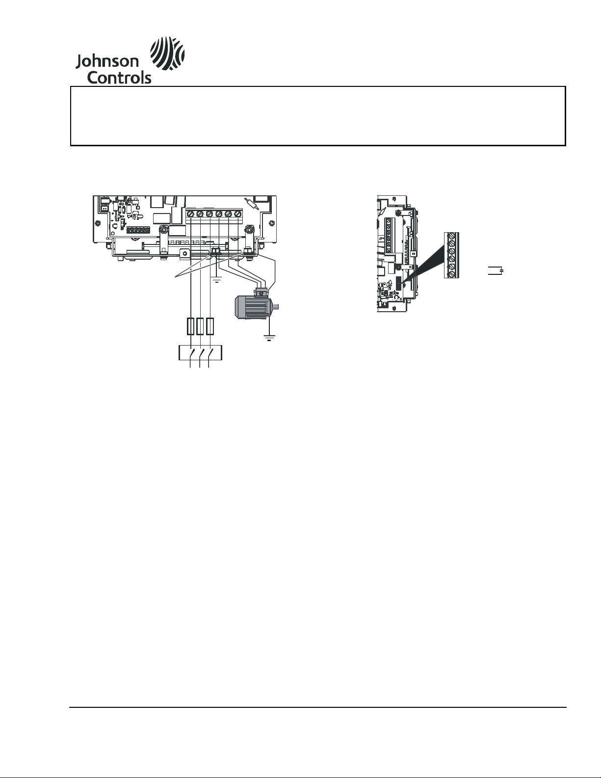
VFD66 Series Condenser Fan Speed Controls
Optional
Ground
Connection
Fuses
FIG:trmnl_cnnctns
Ground Connection
Terminals (For Power
and Motor Ground)
Supply
Ground
TB2
L3/T
L2/S
L1/R
T1/U
T2/V
T3/W
Mains Supply
A: Alarm
B: Alarm
1: +5V Output
2: Analog Input 1
3: Analog Input 2
FIG:cntrl_cnnctns
TB1
4: 0V Common
Quick Start Commissioning Guide VFD66xxx-2 Series
Issue Date July 15, 2011
Electrical Connections
Figure 1: VFD66xxx-2
Power Terminal Connections
Manual Operation
Operating the VFD66 Control from the Keypad
VFD66xxx-1 Setup
The speed is controlled with P1 (P2 is not used).
J2 = On, J3 = On, and J7 = On or Off.
Figure 2: VFD66xxx-2
Control Connections
VFD66xxx-2 Setup
Set parameter 05 to PAd (manual input mode).
Press the green button on the keyboard to run;
press the red button to stop.
Use the up arrow key to increase the speed; use
the down arrow key to decrease the speed.
Note: If you cycle the power, the VFD66xxx-2 stops
and you must press the green button again.
© 2011 Johnson Controls, Inc. 1
Part No. 24-10511-112, Rev. — www.johnsoncontrols.com
Page 2

)
Max. Pressure Rating of Sensor
(
10 + 80 x
Desired Pressure Setpoint
]
Max. Pressure Rating of Sensor
[
80 x
(Pressure Setpoint – Min. Req. Pressure)
Operating the VFD66 Control with a P35 Pressure Transducer or Any 0 to 5 VDC Signal
VFD66xxx-1 Setup
J2 = On, J3 = Off, and J7 = On.
P1 = minimum speed.
P2 = minimum speed maintain (stop or hold).
Operating the VFD66 Control with a C450 Control Module or Any 0 to 10 VDC Signal
VFD66xxx-1 Setup
J2 = On, J3 = Off, and J7 = Off.
VFD66xxx-2 Setup
Set parameter 05 to Std (standard input mode;
factory default setting).
Set parameter 65 to 5V (factory default setting).
Set parameter 67 for the desired minimum speed
(factory default setting is 0 Hz).
Set parameter 64 for either stop (factory default
setting; motor stops below the minimum speed
setting) or HOLd (motor idles), to obtain the
desired action at the minimum speed point.
VFD66xxx-2 Setup
Set parameter 05 to Std (factory default setting).
Set parameter 65 to 10V.
Set parameter 67 for the desired minimum speed
(factory default setting is 0 Hz).
Set parameter 64 for either stop (factory default
setting) or HOLd, to obtain the desired action at
the minimum speed point.
Operating the VFD66 Control with a Ratiometric P499 Series Electronic Pressure Transducer
VFD66xxx-1 Setup
J2 = Off, J3 = On or Off, and J7 = On or Off.
P1 = setpoint.
P2 = proportional band.
VFD66xxx-2 Setup
Set parameter 05 to EPt (electronic pressure
transducer input mode).
Set parameter 65 to 5V (factory default setting) for
ratiometric sensors; set parameter 65 to 10V for
0 to 10 VDC sensors.
Set parameter 61 for the desired setpoint. This
setting is calculated using the following equation:
Example: If a 0 to 500 psig sensor is used and the
desired setpoint is 275 psig, then the setting for
parameter 61 is 10 + (80 x 275/500) or 54.
Set parameter 62 for the desired proportional band
of the control. This setting is calculated using the
following equation:
Example: If a 0 to 750 psig sensor with a setpoint
of 500 psig and a minimum required pressure of
410 psig is used, then the setting for parameter 62
is 80 x [(500 – 410)/750] or 9.6.
2 VFD66 Series Condenser Fan Speed Controls Quick Start Commissioning Guide
Page 3

60
Desired Acceleration Rate x 100
60
Desired Deceleration Rate x 100
Building Efficiency
507 E. Michigan Street, Milwaukee, WI 53202
Johnson Controls/PENN® and Johnson Controls® are registered trademarks of Johnson Controls, Inc.
All other marks herein are the marks of their respective owners. © 2011 Johnson Controls, Inc.
Changing Acceleration and Deceleration Parameters on the VFD66 Control
VFD66xxx-1 Setup
If J4 = On, then the acceleration and deceleration
rate is 5 seconds (this value is in seconds/60Hz).
If J4 = Off, then the acceleration and deceleration
rate is 30 seconds (this value is in
seconds/60 Hz).
VFD66xxx-2 Setup
Set parameter 03 for acceleration
(in seconds/100 Hz). This setting is calculated
using the following equation:
Example: A setting of 8.3 (in seconds/100 Hz)
equals a 5 second acceleration rate from
0 to 60 Hz.
Set parameter 04 for deceleration
(in seconds/100 Hz). This setting is calculated
using the following equation:
Example: A setting of 50 (in seconds/100 Hz)
equals a 30 second deceleration rate from
0 to 60 Hz.
Note: The settings for the acceleration and
deceleration parameters are adjustable from
0 to 3,200 seconds (this range is in seconds/100 Hz).
Selecting Single or Dual Sensors (High Signal Select) on the VFD66 Control
VFD66xxx-1 Setup
If J8 = On, then dual sensors are configured with
high signal select.
If J8 = Off, then single sensor is configured.
VFD66xxx-2 Setup
Set parameter 63 to 1InP (factory default setting)
for single sensor configuration.
Set parameter 63 to 2InP for dual sensor
configuration with high signal select.
Setting the Motor Rated Frequency on the VFD66 Control
VFD66xxx-1 Setup
If J9 = On, then the motor rated frequency is
50 Hz.
VFD66xxx-2 Setup
Set parameter 39 to the motor rated frequency
(factory default setting is 60 Hz).
If J9 = Off, then the motor rated frequency is
60 Hz.
VFD66 Series Condenser Fan Speed Controls Quick Start Commissioning Guide 3
 Loading...