

Page 1
User Guide
VFD66 Drive
AC variable speed drive for
3 phase induction motors
from 0.75kW to 2.2kW,
1hp to 3hp
Part Number: 24-10511-90
Issue: 2
Page 2

General Information
The manufacturer accepts no liability for any consequences resulting from inappropriate, negligent
or incorrect installation or adjustment of the optional parameters of the equipment or from
mismatching the variable speed drive with the motor.
The contents of this guide are believed to be correct at the time of printing. In the interests of
commitment to a policy of continuous development and improvement, the manufacturer reserves the
right to change the specification of the product or its performance, or the content of the guide without
notice.
All rights reserved. No parts of this guide may be reproduced or transmitted in any form or by any
means, electrical or mechanical including, photocopying, recording or by an information storage or
retrieval system, without permission in writing from the publisher.
Drive software version
This product is supplied with the latest version of user-interface and machine control software. If this
product is to be used in a new or existing system with other drives, there may be some differences
between their software and the software in this product. These differences may cause the product
to function differently. If there is any doubt, please contact Johnson Controls.
Copyright © March 2011
Issue: 2
Software: 01.01.00
Page 3

Contents
1 Safety information ...............................................................6
1.1 Warnings, cautions and notes ................................................................. 6
1.2 Electrical safety - general warning ..........................................................6
1.3 System design and safety of personnel ..................................................6
1.4 Environmental limits ................................................................................6
1.5 Access .....................................................................................................7
1.6 Motor .......................................................................................................7
1.7 Adjusting parameters ..............................................................................7
1.8 Electrical installation ................................................................................7
2 Rating data ...........................................................................9
2.1 Supply types ............................................................................................9
2.2 Supply imbalance .................................................................................... 9
2.3 Maximum motor cable length ..................................................................9
2.4 Multi-motor capability ..............................................................................9
3 Mechanical installation .....................................................10
3.1 Accessing the interior ............................................................................ 11
4 Electrical installation ........................................................12
4.1 VFD66 drive ..........................................................................................12
4.2 Ground leakage .....................................................................................13
4.3 EMC ......................................................................................................14
4.4 Control terminals I/O specification .........................................................18
5 De-rating ............................................................................21
5.1 De-rating information .............................................................................21
5.2 Altitude de-rating ...................................................................................22
6 Keypad and display ..........................................................23
6.1 Programming keys ................................................................................23
6.2 Control keys ..........................................................................................23
6.3 Selecting and changing parameters ......................................................24
6.4 Saving parameters ................................................................................25
6.5 Parameter access .................................................................................25
6.6 Security codes .......................................................................................25
6.7 Setting drive back to default values ....................................................... 26
7 Parameters .........................................................................27
7.1 Parameter descriptions - level 1 ............................................................27
7.2 Parameter descriptions - level 2 ............................................................32
7.3 Parameter descriptions - level 3 ............................................................35
7.4 Diagnostic parameters ..........................................................................35
8 Diagnostics ........................................................................36
8.1 Fault clearing .........................................................................................37
8.2 Repairs and replacements ....................................................................37
VFD66 User Guide
Issue Number: 2 www.johnsoncontrols.com
Page 4

9 Technical specifications .................................................. 38
10 UL listing information ....................................................... 39
10.1 UL information .......................................................................................39
www.johnsoncontrols.com Issue Number: 2
VFD66 User Guide
Page 5
EC Declaration of Conformity
PDM Name: EU-DOC-VFD66-Variable Frequency Drive.doc
Manufacturer: Johnson Controls Inc.
Address:
Country: USA
Phone number: 859-283-1384
Description: Variable Frequency Drive for 3 phase induction motors
Product name: VFD66
Brand: Johnson Controls / Penn
Identification
Therefore this product complies with the essential requirements and provisions of the Directives.
The Technical documentation can be requested by the surveillance Authorities at the following address:
Company:
Address, City: Christian X’s Vej 201, 8270 Hoejbjerg
Country: Denmark
Phone number: + 45 8736 7000
4620 Olympic Blvd
Erlanger KY 41018-0000
Certify and declare under our sole responsibility that the following:
VFD66 followed by A,B,C,D,E,F,J or K followed by two letters. All can be followed by up
to three additional numbers followed by up to two additional letters.
conforms with the essential requirements of the following directives:
EMC Directive 2004/108/EC
Low Voltage Directive 2006/95/EC
The following harmonised standards have been applied:
EN 61800-5-1:2007
EN 61800-3:2004
EN 61000-6-2:2005
EN 61000-6-4:2007
EN 61000-3-2:2006
EN 61000-3-3:2008
EN 61000-3-2:2006: Applicable where input current <16A.
No limits apply for professional equipment where input power >1kW.
Johnson Controls Inc.
Att: Environment & Legislation
Name and position of person authorised by the manufacturer:
Date: 1/21/2011
George Rudich
Engineering Manager
Johnson Controls Inc
VFD66 User Guide 5
Issue Number: 2 www.johnsoncontrols.com
Page 6
1 Safety information
WARNING
CAUT ION
NOTE
1.1 Warnings, cautions and notes
A Warning contains information, which is essential for avoiding a safety hazard.
A Caution contains information, which is necessary for avoiding a risk of damage to the
product or other equipment.
A Note contains information, which helps to ensure correct operation of the product.
1.2 Electrical safety - general warning
The voltages used in the drive can cause severe electrical shock and/or burns, and
could be lethal. Extreme care is necessary at all times when working with or adjacent to
the drive.
Specific warnings are given at the relevant places in this guide.
1.3 System design and safety of personnel
The drive is intended as a component for professional incorporation into complete
equipment or system. If installed incorrectly, the drive may present a safety hazard.
The drive uses high voltages and currents, carries a high level of stored electrical
energy, and is used to control equipment which can cause injury.
System design, installation, commissioning / start up and maintenance must be carried
out by personnel who have the necessary training and experience. They must read this
safety information and this guide carefully.
The STOP and START controls or electrical inputs of the drive must not be relied
upon to ensure safety of personnel. They do not isolate dangerous voltages from
the output of the drive. The supply must be disconnected by an approved
electrical isolation device before gaining access to the electrical connections.
The drive is not intended to be used for safety-related functions.
Careful consideration must be given to the function of the drive which might result in a
hazard, either through its intended behavior or through incorrect operation due to a
fault. In any application where a malfunction of the drive or its control system could lead
to or allow damage, loss or injury, a risk analysis must be carried out, and where
necessary, further measures taken to reduce the risk.
1.4 Environmental limits
Instructions within the supplied data regarding transport, storage, installation and the
use of the drive must be complied with, including the specified environmental limits.
6 VFD66 User Guide
www.johnsoncontrols.com Issue Number: 2
Page 7
1.5 Access
WARNING
Access must be restricted to authorized personnel only. Safety regulations which apply
at the place of use must be complied with. The IP (Ingress Protection) rating of the drive
is installation dependant.
information
Safety
1.6 Motor
Ensure the motor is installed in accordance with the manufacturer's recommendations.
Ensure the motor shaft is not exposed.
Standard squirrel cage induction motors are designed for single speed operation. If it is
intended to use the capability of a drive to run a motor at speeds above its designed
maximum, it is strongly recommended that the manufacturer is consulted first.
Low speeds may cause the motor to overheat because the cooling fan becomes less
effective. If necessary, an electric force vent fan should be used.
1.7 Adjusting parameters
Some parameters have a profound effect on the operation of the drive. They must not
be altered without careful consideration of the impact on the controlled system.
Measures must be taken to prevent unwanted changes due to error or tampering.
1.8 Electrical installation
1.8.1 Electric shock risk
The voltages present in the following locations can cause severe electric shock and may
be lethal:
• AC supply cables and connections
• Output cables and connections
• Many internal parts of the drive
Unless otherwise indicated, control terminals are single insulated and must not be
touched.
1.8.2 Isolation device
The AC supply must be disconnected from the drive using an approved isolation device
before any cover is removed from the drive or before any servicing work is performed.
1.8.3 STOP function
The STOP function does not remove dangerous voltages from the drive or the motor.
1.8.4 Ground leakage current
The drive is supplied with an internal EMC filter capacitor installed. If the input voltage to
the drive is supplied through an ELCB or RCD, these may trip due to the ground
leakage current. See section 4.3.1 Internal EMC filter on page 14 for further information
and how to disconnect the internal EMC capacitor.
The VFD66 series variable speed drives are intended to control equipment under normal
operating conditions. Where failure or malfunction of a VFD66 drive could lead to an
abnormal operating condition that could cause personal injury or damage to the
equipment or other property, other devices, (limit or safety controls) or systems (alarm or
supervisory) intended to warn of, or protect against, failure or malfunction of the VFD66
drive must be incorporated into and maintained as part of the control system.
Rating data
Mechanical
installation
installation
Electrical
De-rating
Keypad and
display
Parameters Diagnostics
specifications
Technical
UL Listing
VFD66 User Guide 7
Issue Number: 2 www.johnsoncontrols.com
Page 8
Risk of thermal damage
CAUT ION
CAUT ION
WARNING
WARNING
CAUT ION
The VFD66 control can generate and dissipate significant heat. Mount the control on a
metal, concrete, or cinderblock mounting surface. Mounting the VFD66 control on
surfaces made of wood or other heat-sensitive material may result in damage to the
mounting surface.
Risk of equipment damage
Motors used with the VFD66 controls must meet certain specifications for proper
performance and operation. Motors that do not meet these specifications may be
damaged.
Risk of electrical shock
The printed wiring board and its components are at AC line voltage. Direct or indirect
contact with line voltage can result in personal injury or death.
Risk of electrical shock
The VFD66 drive remains electrically charged for a period of time after the power is
removed. To avoid possible electrical shock, wait at least 10 minutes after AC supply
power has been disconnected from the VFD66 drive before servicing the control. Failure
to wait until the VFD66 drive fully discharges could cause electrical shock, personal
injury, or death.
Risk of equipment damage
Connect each of these items to the VFD66 drive using a separate conduit for each set
of wires:
• Line voltage supply power
• Line voltage output power to motor
• Low voltage signals from input devices
Running different voltage and frequency wires in the same conduit can create electronic
noise or harmonics, which may damage the condenser fan motors.
8 VFD66 User Guide
www.johnsoncontrols.com Issue Number: 2
Page 9
2Rating data
NOTE
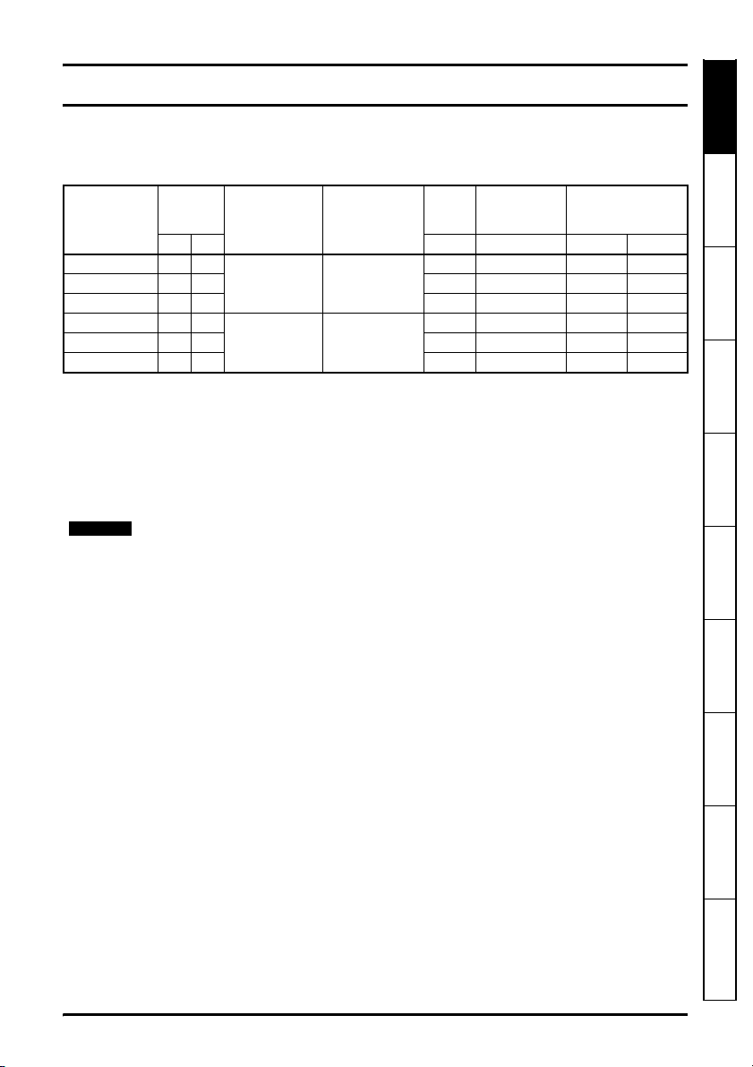
The following information describes the electrical and mechanical ratings for the range
of Johnson Controls drives.
Table 2-1 VFD66 model numbers and ratings
Input
Motor
Model
Number
VFD66AAA-2 0.75 1.0
VFD66CAA-2 1.5 2.0 13 9.9 7.5 6.2
VFD66EBA-2* 2.2 3.0 16 13.1 10.6 9.0
VFD66BAA-2 0.75 1.0
VFD66DAA-2 1.5 2.0 8 5.7 3.6 3.6
VFD66FAA-2 2.2 3.0 10 7.5 5.5 5.5
power
kW hp A A 50°C60°C
Supply voltage
and frequency
3 phase 200 to
±10%
240Vac
48 to 65Hz
3 phase 380 to
±10%
480Vac
48 to 65Hz
Output voltage
and frequency
Three phase
0 to 240Vac
0 to 1500Hz
Three phase
0 to 480Vac
0 to 1500Hz
*With fan
Overload capacity
110% of output current for 1 minute.
Output frequency
0 to 1500Hz
Output voltage
3 phase, 0 to drive rating (240 or 480Vac maximum set by Pr 08).
The output frequency can be increased by 20% during deceleration.
2.1 Supply types
The drive is suitable for use on:
Star and Delta connected supplies
Three phase supplies with a grounded star point neutral configuration.
Three phase supplies with a line grounded delta configuration.
Ground supplies
Supplies with ground configurations TN, TN-C, and TN-S.
Floating supplies
IT supply configurations
Typical RMS
fuse
rating
10 6.3 4.0 4.0
63.51.81.8
input
current
Rated RMS output
current (A)
information
installation
installation
display
Safety
Rating data
Mechanical
Electrical
De-rating
Keypad and
Parameters Diagnostics
2.2 Supply imbalance
The maximum supply imbalance: 2% negative phase sequence as per IEC 60146-1-1.
2.3 Maximum motor cable length
50m (165 ft) maximum from the motor.
2.4 Multi-motor capability
The VFD66 drive is capable of operating multiple motors at a common frequency as
long as the total current is less than or equal to the drive rating. Individual motor
protection must be provided and the output of the drive should be chain connected to
the motors. The fixed V/F mode (Pr 41 = Fd) should be used.
VFD66 User Guide 9
Issue Number: 2 www.johnsoncontrols.com
specifications
Technical
UL Listing
Page 10
3 Mechanical installation
mm (7
.5in)
190
mm (7.0in)178
mm (6.2in)158
mm (3.4in)86
mm (3.5in)89
mm (8.1in)206
mm (1.5in)38
Terminal cover
screw
Terminal access
cover
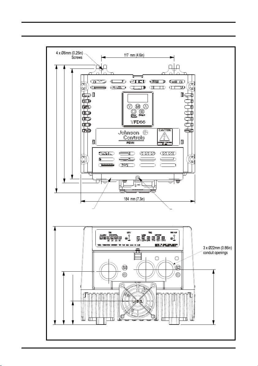
Figure 3-1 VFD66 drive basic dimensions
10 VFD66 User Guide
www.johnsoncontrols.com Issue Number: 2
Page 11
Enclosure
WARNING
WARNING
The drive is intended to be mounted in an enclosure which prevents access except by
trained and authorized personnel, and which prevents the ingress of contamination. It is
designed for use in an environment classified as pollution degree 2 in accordance with
IEC 60664-1. This means that only dry, non-conducting contamination is acceptable.
The VFD66 drive can generate and dissipate significant heat. Mount the drive on a metal,
concrete or cinder block mounting surface. Mounting the VFD66 drive on surfaces made
of wood or other heat-sensitive material may result in damage to the mounting surface.
Safety information Rating data
Observe the following the guidelines when mounting a VFD66 drive:
• Mount the VFD66 drive on a vertical surface with the heatsink fins oriented vertically
and the conduit holes facing down.
• Provide a minimum of 4 in. (102 mm) clearance around the heatsink.
• Ensure that output power wiring between the VFD66 drive and the motor does not
exceed 50m (165 ft).
Mount the VFD66 drive in a location protected from condensation, explosive vapours,
corrosive gas, water, and dust.
3.1 Accessing the interior
Remove the terminal access cover by removing the terminal cover screw (see Figure 3-
1) to access terminal blocks, ground connections, EMC filter link and MOV link (see
Figure 4-1, Figure 4-2, Figure 4-3 and Figure 4-4).
NEMA 1 enclosure
Follow the following steps to remove the terminal cover:
1. Remove the terminal cover screw and push upwards on the front of the cover.
2. Pull outward on the top of the terminal access cover.
installation
installation
display
Mechanical
Electrical
De-rating
Keypad and
Parameters Diagnostics
VFD66 User Guide 11
Issue Number: 2 www.johnsoncontrols.com
specifications
Technical
UL Listing
Page 12
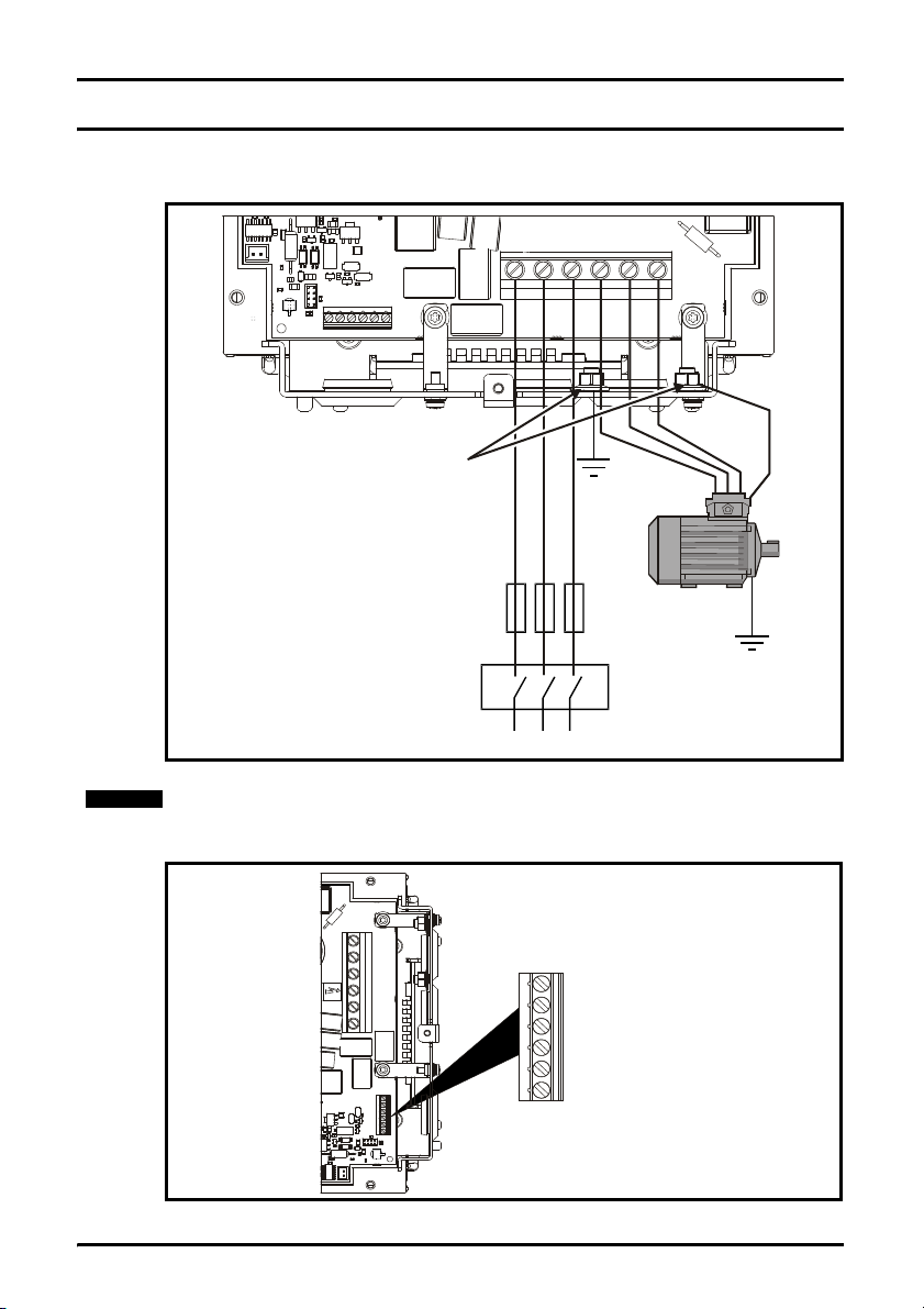
4 Electrical installation
Optional
ground
connection
Fuses
Mains supply
Ground
connection terminals
(for power and motor ground)
TB2
L3/T
L2/S
L1/R
T1/U
T2/V
T3/W
Supply
ground
NOTE
A Alarm output 1
B Alarm output 2
1 +5V output
2 Analog input 1
3 Analog input 2
4 0V common
TB1
4.1 VFD66 drive
Figure 4-1 VFD66 drive power terminal connections
Two M5 locknuts are installed on the ground connection terminals
Figure 4-2 VFD66 drive control connections
12 VFD66 User Guide
www.johnsoncontrols.com Issue Number: 2
Page 13

Fuses/MCB
WARNING
WARNING
NOTE
NOTE
WARNING
The AC supply to the drive must be installed with suitable protection against overload
and short circuits. Failure to observe this requirement will cause risk of fire.
The drive must be grounded by a conductor sufficient to carry the prospective fault
current in the event of a fault. See also the warning in section 4.2 Ground leakage
relating to ground leakage current.
Safety information Rating data
Model Maximum power terminal screw torque
VFD66 0.5 Nm / 4.4 lb in
4.2 Ground leakage
The ground leakage current depends upon the internal EMC filter being installed. The
drive is supplied with the filter installed. Instructions for removal of the internal EMC filter
are given in section 4.3.2 Removing the internal EMC filter .
With internal EMC filter installed
3 Phase 200V drives
7.8mA AC maximum at 220V, 50Hz (proportional to supply voltage and frequency).
3 Phase 200V drives
10.4mA AC maximum at 400V, 50Hz (proportional to supply voltage and frequency).
The above leakage currents are the leakage currents of the drive with the Internal EMC
filter connected. No account is taken for leakage currents of the motor or motor cable.
With internal EMC filter removed <1mA
There is an internal voltage surge suppression device connected to ground. Under
normal circumstances, this carries negligible current.
When the internal EMC filter is installed, the leakage current is high. In this case, a
permanent fixed ground connection must be provided.
4.2.1 Use of ground fault circuit interrupter (GFCI)
There are three common types of GFCI:
Type AC - detects AC fault currents
Type A - detects AC and pulsating DC fault currents (provided the DC current
reaches zero at least once every half cycle)
Type B - detects AC, pulsating DC and smooth DC fault currents
• Type AC should never be used with drives
• Type A can only be used with single phase drives
• Type B must be used with three phase drives
Mechanical
installation
installation
Electrical
De-rating
Keypad and
display
Parameters Diagnostics
specifications
Technical
UL Listing
VFD66 User Guide 13
Issue Number: 2 www.johnsoncontrols.com
Page 14

4.3 EMC
Remove
screw S2
PCB screw
EMC filter
link
1
234
+
Remove
screw S1
Internal MOV link
1
3
PCB screw
2
4
+
4.3.1 Internal EMC filter
It is recommended that the internal EMC filter is kept in place unless there is a specific
reason for removing it.
It is recommended that the filter be used in all applications unless the ground leakage
current is unacceptable.
4.3.2 Removing the internal EMC filter
Figure 4-3 Removal of the VFD66 internal EMC filter
To disconnect the VFD66 internal EMC filter:
1. Remove the front panel Torx T10 screw (S2).
2. Loosen the PCB Torx T10 screw.
3. Remove the EMC filter link.
4. Re-tighten the Torx T10 PCB screw to 1 Nm (8.9 Ib in).
Removal of the MOV varistor
A MOV (varistor) is installed between the power circuit and ground in order to protect
the drive from high voltage impulses caused by lightning etc. In some applications it
may be necessary to disconnect this device , depending upon the applicable
regulations - for example if there is no fixed ground connection.
Figure 4-4 Removal of the VFD66 internal MOV
To disconnect the VFD66 internal MOV:
1. Remove the front panel Torx T10 screw (S1).
14 VFD66 User Guide
2. Loosen the PCB Torx T10 screw.
3. Remove the internal MOV link.
4. Re-tighten the Torx T10 PCB screw to 1 Nm (8.9 Ib in).
www.johnsoncontrols.com Issue Number: 2
Page 15

4.3.3 Emissions Compliance
An internal factory installed EMC filter is provided with all ratings, it is recommended
that it is kept in place unless there is a specific reason for removing it. This internal filter
reduces radio-frequency emissions into the line power supply. When the motor cable is
short, it permits the requirements of EN61800-3:2004 to be met for the second
environment with restricted distribution. For longer motor cables, the filter continues to
provide a useful reduction in emission level. When used with any length shielded motor
cable (up to the limit for the drive), it is unlikely that nearby industrial equipment will be
disturbed.
Installation of an additional external EMC filter as shown in Table 4-1, provides higher
levels of emissions compliance. If the application requires these levels of compliance
then the external filter must be installed in order to ensure compliance with EMC
regulations such as the EC EMC Directive, and to ensure the validity of the CE mark.
Table 4-1 Emmisions compliance for VFD66 based on EMC filter configuration
Motor
Cable
Length m
(ft)
1 (3) C4C4C4 C2 C2 C3 C2 C2 C3
5 (16) C4 C4 C4 C2 C2 C3 C2 C2 C3
10 (33) C4 C4 C4 C2 C3 C3 C3 C3 C3
15 (50) C4 C4 C4 C2 C3 C3 C3 C3 C3
25 (82) C4 C4 C4 C2 C3 C3 C3 C3 C3
50 (164)C4C4C4 C2 C3 C3 C3 C3 C3
Internal Filter Only Standard Filter Low Leakage Filter
3kHz 6kHz 12kHz 3kHz 6kHz 12kHz 3kHz 6kHz 12kHz
*The typical leakage current of the low leakage filter is 3mA compared to the standard
filter which has a typical leakage current of 40mA.
Table 4-2 Key to conformity
Compliance
Level
C2
C3
C4
Standard Description Frequency
EN 610006-4:2007
EN 618003:2004
IEC 61800-3
EN 618003:2004
IEC 61800-3
Generic emission
standard for the
Industrial
Environment
Product standard
for adjustable
power drive
systems.
Product standard
for adjustable
power drive
systems.
Notes:
(1) The first environment is one where the low voltage supply network also supplies
residential premises
(2) When distribution is restricted, drives are available only to installer with EMC
competence.
Filter and Switching Frequency
Schaffner P/N: FS6514-14-07 Schaffner P/N: FS6514-14-07-LL*
Range
0.15 – 0.50
MHz
0.50 – 30
MHz
Requirements for the first environment (1) with restricted
distribution (2).
Requirements for the second environment with unrestricted
distribution.
Requirements for the second environment with restricted
distribution (2).
Limits Application
79dBμV quasi peak
66dBμV average
73dBμV quasi peak
60dBμV average
AC Supply Lines
Safety information Rating data
Mechanical
installation
installation
Electrical
De-rating
Keypad and
display
Parameters Diagnostics
specifications
Technical
UL Listing
VFD66 User Guide 15
Issue Number: 2 www.johnsoncontrols.com
Page 16

(3) Operation without an external filter is a practical cost-effective possibility in an
Shielded
wiring
TB2
VFD66
Control
Motor
ground
*
TB1
EL1 L2
L3
L1 L2 L3
E
EMC
filter
AB34
Input
device(s)
Alarm
device
Supply
ground
*
L3/T
L2/S
L1/R
T1/U
T2/V
T3/W
12
NOTE
industrial installation where existing levels of electrical noise are likely to be high, and
any electronic equipment in operation has been designed for such an environment. This
is in accordance with EN 61800-3:2004 in the second environment, with restricted
distribution. There is some risk of disturbance to other equipment, and in this case the
user and supplier of the drive system must jointly take responsibility for correcting any
problem which occurs.
Figure 4-5 CE Compliance Wiring
* The M5 nuts are provided to connect the shield to ground (earth).
• Physically separate the input and output cables.
• All input and output cables should be fully shielded, with the shield securely
grounded. The motor cable shield should be connected to the ground connection.
• Do not run input cables alongside output cables. Do not bundle input and output
cables together.
• The input ground wire should be connected to the ground connection.
• Ideally, the motor cable shield should be clamped directly to the back plate.
• The EMC filter body needs to be fixed to the same grounded metal part (e.g. the
back plate) as the motor cable shield.
www.johnsoncontrols.com Issue Number: 2
16 VFD66 User Guide
Page 17

4.3.4 Immunity Compliance
The level of the drives immunity from conducted and radiated emissions from external
sources is summarised below in Table 4-3.
Table 4-3 Immunity compliance
Standard Type of immunity Test specification Application Level
IEC 61000-4-2
EN 61000-4-2
IEC 61000-4-3
EN 61000-4-3
IEC 61000-4-4
EN 61000-4-4
IEC 61000-4-5
EN 61000-4-5 Surges
IEC 61000-4-6
EN 61000-4-6
IEC 61000-4-11
EN 61000-4-11
IEC 61000-6-1
EN 61000-6-
1:2007
IEC 61000-6-2
EN 61000-6-
2:2005
IEC 61800-3
EN 61800-3:2004
Electrostatic
discharge
Radio frequency
radiated field
6kV contact discharge
8kV air discharge
10V/m prior to modulation
80 – 1000MHz
80% AM (1kHz)
modulation
5/50ns 2kV transient at
5kHz repetition
Fast transient
burst
frequency via coupling
clamp
5/50ns 2kV transient at
5kHz repetition frequency
by direct injection
Common mode 4kV
1.2/50µs waveshape
Differential mode 2kV
1.2/50µs waveshape
Lines to ground
Conducted radio
frequency
10V prior to modulation
0.15 – 80MHz
80% AM (1kHz)
modulation
Voltage dips and
interruptions
Generic immunity standard for the residential,
commercial and light – industrial environment
Generic immunity standard for the industrial
environment
-30% 10ms
+60% 100ms
-60% 1s
<-95% 5s
Product standard for adjustable speed power
drive systems (immunity requirements)
Module enclosure
Module enclosure
Control lines
(industrial harsh)
Power lines
AC supply lines:
Line to ground
AC supply lines:
Line to line
Signal ports to
ground
Control and power
lines
AC power ports
Meets immunity requirements for first and
second environments
Level 3
(industrial)
Level 3
(industrial)
Level 4
Level 3
(industrial)
Level 4
Level 3
Level 2
Level 3
(industrial)
Complies
Complies
Safety information Rating data
Mechanical
installation
installation
Electrical
De-rating
Keypad and
display
Parameters Diagnostics
VFD66 User Guide 17
Issue Number: 2 www.johnsoncontrols.com
specifications
Technical
UL Listing
Page 18

4.4 Control terminals I/O specification
WARNING
WARNING
The control circuits are isolated from the power circuits in the drive by basic insulation
(single insulation) only. The installer must ensure that the external control circuits are
insulated from human contact by at least one layer of insulation (supplementary
insulation) rated for use at the AC supply voltage.
If the control circuits are to be connected to other circuits classified as Safety Extra Low
Voltage (SELV) (e.g. to personal computer), an additional isolating barrier must be
included in order to maintain the SELV classification.
4.4.1 VFD66 control connections
Alarm output 1 - drive OK (normally open)*
A
Voltage rating 5-24Vac or 5-30Vdc
Current rating
Alarm output 2
B
+5V output
1
Max current rating 20mA (short circuit proof)
Analog reference input 1
2
Voltage 0 to +5V / 0 to +10V
Input impedance 100kΩ
Resolution 0.1%
Accuracy ±5%
Sample time 6ms
100μA at 24V minimum / 200mA maximum
Analog reference input 2
3
Voltage 0 to +5V / 0 to +10V
Input impedance 100kΩ
Resolution 0.1%
Accuracy ±5%
Sample time 6ms
0V Common
4
* Used with class 2 circuits.
4.4.2 Wiring input devices to a VFD66
Connect the appropriate low-voltage input signal device to Terminal Block TB1 (Figure
4-2 on page 12). See Table 4-4 below, Figure 4-6 on page 19, Figure 4-7 on page 19,
and Figure 4-8 on page 20 for additional information on wiring specific Johnson
Controls/PENN™ input devices to the VFD66 controls.
18 VFD66 User Guide
www.johnsoncontrols.com Issue Number: 2
Page 19

Table 4-4 Wiring Johnson Controls/PENN input devices
TB1
2
1
3
P35 Transducer
Second P35 transducer (optional)
3
421
1
2
3
White
(second output signal)
Red (5 Vdc supply)
White
(output signal)
TB1
Black (common)
Red (5 VDC Supply)
Black
(common)
341
2
Input Device Input Device Terminal VFD66 Control TB1 Terminal
11
P35AG-9200R Transducer
C450CPN control module
C450CQN control module
P499 Series Transducers
2
34
AO1 2
COM 4
AO1 2
AO2 3
COM 4
Red 1
White
Black 4
2 (or 3)
2 (or 3)
1
1
Input Devices
1
Use terminal 3 to connect an optional second input device to the VFD66 as shown in
Figure 4-6 and Figure 4-7 below.
Figure 4-6 Wiring P35 transducers to VFD66 terminal block TB1
Safety information Rating data
Mechanical
installation
installation
Electrical
De-rating
Keypad and
display
Figure 4-7 Wiring P499 transducers to VFD66 terminal block TB1
VFD66 User Guide 19
Issue Number: 2 www.johnsoncontrols.com
Parameters Diagnostics
specifications
Technical
UL Listing
Page 20

Figure 4-8 Wiring C450CPN control module or C450CQN control module to VFD66
C450CQN
Control module
two analog outputs
AO2
COM
AO1
C450CPN
Control module
one analog output
COM
AO1
2
4
V
C
S
1
C
S
2
C
S
3
5
V
2
4
V
C
S
1
C
S
2
C
S
3
5
V
TB1
TB1
3421
3
4
21
NOTE
Visual
or Audible
External Alarm
Device
Alarm output
is rated for 100mA
at 30Vdc / 24Vac
BA
24Vac / 30 Vdc
VFD66 Control
Terminal Block TB1
Terminal Block TB1
The VFD66 controls work with most 0 to 5Vdc or 0 to 10Vdc electronic pressure
transducers. For best results, use 0 to 5Vdc, ratiometric P499 Electronic Pressure
Transducers. Ratiometric transducers vary the signal voltage from 10 to 90% of the 5Vdc
supply power as the pressure goes from minimum to maximum of the transducer rating.
Applications using a 0 to 10 Vdc transducer must be powered separately.
4.4.3 Wiring an external alarm to a VFD66 control
20 VFD66 User Guide
The Metal Oxide Silicon Field Effect Transistor (MOSFET) alarm output activates when
a permanent fault condition occurs. See Figure 4-9 below.
Figure 4-9 Wiring the alarm output
Wiring the VFD66 input and output power
Select a wire size for field wiring based on a wire insulation temperature resistance
rating of 75
°C (167°F), with a maximum wire size of 12 AWG. Use only stranded copper
wire, rated for at least 600 volts.
www.johnsoncontrols.com Issue Number: 2
Page 21

Amps
12
10
8
6
4
2
104 F° 122 F°
140 F
°
0
Temperature
VFD66AAA
VFD66CAA
VFD66EBA
40°C 50°C 60°C
NOTE
5 De-rating
5.1 De-rating information
Figure 5-1 200/230 Vac Temperature De-Rating
No de-rating for 400/460 Vac drives up to 60°C (140°F). Contact JCI application
engineering for 6KHz and 12KHz versions
This is the de-rating with the switching frequency at 3kHz.
De-Rating examples
For these examples, the drive used is a VFD66EBA type. See Figure 5-1 and Table 5-1.
• If the VFD66EBA drive is used in Denver, Colorado (altitude 5200 ft), the output
rating is reduced (see Table 5-1). When the temperature is less than 122°F (50°C),
the VFD66EBA drive is rated for 9.96 amperes, as shown by the equation:
De-Rated maximum output amperes = 10.6 A x 0.94 = 9.96 amperes
• If the VFD66EBA drive is used in Denver, Colorado (altitude 5200 ft) and the
ambient temperature reaches 140°F (60°C), then the VFD66EBA drive is de-rated
to maximum current of 9.0 amperes due to the high ambient temperature and is
further de-rated to 8.46 amperes because of the high altitude.
De-Rated maximum output amperes = 9.0 amperes x 0.94 = 8.46 amperes.
Safety information Rating data
Mechanical
installation
installation
Electrical
De-rating
Keypad and
display
Parameters Diagnostics
specifications
Technical
VFD66 User Guide 21
Issue Number: 2 www.johnsoncontrols.com
UL Listing
Page 22

5.2 Altitude de-rating
See Table 5-1 for altitude multipliers. Use the following formula to determine the
adjusted rating:
Temperature De-Rated
Maximum Output Amperes
Table 5-1 Altitude multipliers
Altitude Range Altitude Multiplier
0-3300 ft (0-1000 m) 1.0
3300-4300 ft (1000-1305 m) 0.97
4300-5300 ft (1305-1610 m) 0.94
5300-6300 ft (1610-1915 m) 0.91
6300-7300 ft (1915-2220 m) 0.88
7300-8300 ft (2220-2525 m) 0.86
8300-9300 ft (2525-2830 m) 0.83
9300-9842 ft (2830-3000 m) 0.80
X
Altitude
Multiplier
De-Rated Maximum
=
Output Amperes
22 VFD66 User Guide
www.johnsoncontrols.com Issue Number: 2
Page 23

6 Keypad and display
M
The keypad and display are used for the following:
• Displaying the operating status of the drive
• Displaying a fault or trip code
• Reading and changing parameter values
• Stopping, starting and resetting the drive
Figure 6-1 Keypad and display
Safety information Rating data
Mechanical
installation
installation
Electrical
De-rating
Keypad and
display
6.1 Programming keys
The MODE key is used to change the mode of operation of the drive.
The UP and DOWN keys are used to select parameters and edit their values. In
manual input mode, they are used to increase and decrease the speed of the motor.
Parameters Diagnostics
6.2 Control keys
The START key is used to start the drive in manual input mode.
The STOP/RESET key is used to stop and reset the drive.
specifications
Technical
UL Listing
VFD66 User Guide 23
Issue Number: 2 www.johnsoncontrols.com
Page 24

6.3 Selecting and changing parameters
NOTE
M
STATUS MODE
or
PARAMETER VIEW MODE
Select parameter to view
orPress
Parameter number displayed
PARAMETER EDIT MODE
Change parameter value
or
Press
Parameter value displayed
M
M
Press and
hold for 2s
M
M
Parameters
saved
Press and
release
M
Hold
for 2s
4 mins
timeout
/
/
Press and
release
Press and
release
Press and
release
M
MMMMM
M
This procedure is written from the first power up of the drive and assumes no terminals
have been connected, no parameters have been changed and no security has been set.
Figure 6-2
When in Status mode, pressing and holding the MODE key for 2 seconds will
change the display from displaying a speed indication to displaying load indication (or
output current) and vice versa.
Pressing and releasing the MODE key will change the display from status mode to
parameter view mode. In parameter view mode, the display flashes between the
parameter number and the value of that parameter.
Pressing and releasing the MODE key again will change the display from parameter
view mode to parameter edit mode. In parameter edit mode, the display shows the
value in the parameter.
Pressing the MODE key in parameter edit mode will return the drive to the
parameter view mode. If the MODE key is pressed again then the drive will return to
status mode, but if either of the up or down keys are pressed to change the
parameter being viewed before the MODE key is pressed, pressing the MODE
key will change the display to the parameter edit mode again. This allows the user to
very easily change between parameter view and edit modes during commissioning /
start up of the drive.
24 VFD66 User Guide
www.johnsoncontrols.com Issue Number: 2
Page 25

Status Modes
M
M
M
Display Status Explanation
Drive ready
Drive inhibited
Mains loss The drive is in mains loss ride through mode.
6.4 Saving parameters
Parameters are automatically saved when the MODE key is pressed when going
from parameter edit mode to parameter view mode.
6.5 Parameter access
There are 3 levels of parameter access controlled by Pr 10. This determines which
parameters are accessible. See Table 6-1.
The setting of the user security Pr 25 determines whether the parameter access is read
only (RO) or read write (RW).
Table 6-1
Parameter access (Pr 10) Parameters accessible
L1 Pr 01 to Pr 10
L2 Pr 01 to Pr 67
L3 Pr 01 to Pr 95
6.6 Security codes
Setting a security code allows view only access to all parameters.
A security code is locked into the drive when Pr 25 is set to any other value than 0 and
then LoC is selected in Pr 10. On pressing the MODE key, Pr 10 is automatically
changed from LoC to L1 and Pr 25 will be automatically set to 0 so as not to reveal the
security code.
Pr 10 may be changed to L2 or L3 to allow view only access to parameters.
6.6.1 Setting a security code
•Set Pr 10 to L2.
•Set Pr 25 to the desired security code e.g. 5
•Set Pr 10 to LoC.
• Press the MODE key
•Pr 10 will now be reset to L1 and Pr 25 will be reset to 0.
• The security code will now be locked into the drive.
• Security will also be set if the drive is powered down after a security code has been
set into Pr 25.
The drive is enabled and ready for a start command. The
output bridge is inactive.
The drive is inhibited because there is no enable command,
or the drive is inhibited during a trip reset.
Safety information Rating data
Mechanical
installation
installation
Electrical
De-rating
Keypad and
display
Parameters Diagnostics
specifications
Technical
UL Listing
VFD66 User Guide 25
Issue Number: 2 www.johnsoncontrols.com
Page 26

6.6.2 Unlocking a security code
MMMMM
• Select parameter to be edited
• Press the MODE key, the display will flash 'CodE'
• Press the UP key to start entering the set security code.
• Enter the correct security code
• Press the MODE key
• If the correct security code has been entered, the display will flash and can now be
adjusted.
• If the security code has been entered incorrectly, the above procedure should be
followed again.
6.6.3 Re-locking security
When a security code has been unlocked and the required parameter changes made, to
re-lock the same security code:
•Set Pr 10 to LoC
• Press the STOP/RESET key
6.6.4 Setting security back to 0 (zero) - no security
•Set Pr 10 to L2
• Go to Pr 25
• Unlock security as described above.
•Set Pr 25 to 0
• Press the MODE key.
6.7 Setting drive back to default values
•Set Pr 10 to L2
•Set Pr 29 to Eur and press the MODE key. This loads 50Hz default parameters.
or
•Set Pr 29 to USA and press the MODE key. This loads 60Hz default parameters.
26 VFD66 User Guide
www.johnsoncontrols.com Issue Number: 2
Page 27

7 Parameters
NOTE
NOTE
M
M
NOTE
Parameters are grouped together into appropriate subsets as follows:
Level 1
Pr 01 to Pr 10: Basic drive set-up parameters
Level 2
Pr 22 to Pr 29: Display / keypad configuration
Pr 33: System configuration
Pr 37 to Pr 42: Motor configuration (non-standard set-up)
Pr 45: Drive software version
Pr 55 to Pr 58: Drive trip log
Pr 61 to Pr 70: Control mode setup
Level 3
Pr 81 to Pr 95: Drive diagnostics parameters
These parameters can be used to optimise the set-up of the drive for the application.
7.1 Parameter descriptions - level 1
No Function Range Defaults Type
Minimum set speed 0 to Pr 02 Hz 0.0 RW
01
Used to set the minimum speed at which the motor will run in both directions.
No Function Range Defaults Type
Maximum set speed 0 to 1500 Hz Eur: 50.0, USA: 60.0 RW
02
Used to set the maximum speed at which the motor will run in both directions.
If Pr 02 is set below Pr 01, Pr 01 will be automatically set to the value of Pr 02.
Safety information Rating data
Mechanical
installation
installation
Electrical
De-rating
Keypad and
display
No Function Range Defaults Type
Acceleration rate
03
Deceleration rate Eur: 5.0, USA: 5
04
0 to 3200.0 s/100Hz
Eur: 5.0, USA: 5
RW
Sets the acceleration and deceleration rate of the motor in both directions in seconds/
100Hz.
With the standard ramp mode, the deceleration rate could be extended automatically by
the drive to prevent over voltage (OV) trips if the load inertia is too high for the
programmed deceleration rate.
No Function Range Defaults Type
Drive configuration PAd, Std, EPt, rES Eur: Std, US: Std RW
05
The setting of Pr 05 automatically sets up the drives configuration.
A change to Pr 05 is set by pressing the MODE key on exit from parameter edit mode.
The drive must be disabled, stopped or tripped for a change to take place. If Pr 05 is
changed while the drive is running, when the MODE key is pressed on exit from
parameter edit mode, Pr 05 will change back to its previous value.
When the setting of Pr 05 is changed, the appropriate drive configuration parameters are
set back to their default values.
VFD66 User Guide 27
Issue Number: 2 www.johnsoncontrols.com
Parameters
Diagnostics
specifications
Technical
UL Listing
Page 28

When the mode is changed in Pr 05 to Std or EPt, if there is an analog reference present
WARNING
Set point
85
Keypad
reference
Motor frequency
Input terminals
Read-write parameter
Read-only parameter
Key
XX.XX
XX.XX
X
of more than 0.5V (5V reference), then the motor may start turning.
The reserved (rES) setting should not be used.
Configuration of VFD66
Configuration Description
PAd Manual input mode
Std Standard input mode
EPt Electronic pressure transducer input mode
rES Reserved
Manual input mode
Manual mode uses the keypad buttons to start and stop the motor, as well as increasing
and decreasing the motor speed. It also allows the user to set a constant motor speed.
This mode will be useful, during installation and repair.
The Set point is the keypad reference and is used as an input, with the speed being
adjustable between 0 to 100%. Transducer input will not have any effect on the speed of
the motor.
Figure 7-1 Manual input mode Pr 05 = PAd
Standard input mode
The VFD66 extensively uses this mode. The majority of input devices compatible with
the drive are used with this mode. The input device determines the set point and
proportional band. The parameters which are used in these modes are
Minimum speed (Pr 67) as a percentage of Maximum speed (Pr 02), range from 0 to
50%.
Action at minimum speed (Pr 64), range Hold or Stop.
Maximum speed (Pr 02), range 0 to 1500Hz.
28 VFD66 User Guide
www.johnsoncontrols.com Issue Number: 2
Page 29

4
5
65
95
94
+
_
85
66
65
Analog
input 1
2 transducer
Input voltage
level 5/10V
Analog
input 1
Analog
input 2
Comparator,
higher of the
two is selected
Motor
frequency
Input voltage
level 5/10V
Analog
input 2
63
Input terminals
Read-write parameter
Read-only parameter
Key
XX.XX
XX.XX
X
Minimum speed
67
64
02
Action at min.
pressure
Max speed
Minimum motor speed set by Pr
67
Analog input
RPM
10%
20%
30%
40%
50%
100%
Curve B:
Pr = 30%
Pr = stop
67
64
0%
Curve C:
Pr = 0%
Pr = stop/hold
67
64
Curve B:
Pr = Stop
Motor shuts off at the minimum
speed set by Pr (30% of max
speed)
64
67
Curve C:
Pr = Hold or Stop
Motor shuts off at the minimum
speed set by Pr (0% of max
speed)
64
67
Curve A:
Pr = Hold
Motor Idles at the minimum speed
set by Pr (40% of )
64
67
max speed
Curve A:
Pr = 40%
Pr = hold
67
64
0% 10% 20% 40% 60% 80% 90% 100%
Figure 7-2 Standard input mode Pr 05 = Std
The Proportional band of the drive will be between the values selected in Pr 67
(0 to 50%) and Maximum speed Pr 02.
Safety information Rating data
Mechanical
installation
installation
Electrical
De-rating
Keypad and
display
VFD66 User Guide 29
Issue Number: 2 www.johnsoncontrols.com
Parameters
Diagnostics
specifications
Technical
UL Listing
Page 30

Electronic pressure transducer input mode
4
5
65
95
94
+
_
85
66
65
Analog
input 1
2 transducer
Input voltage
level 5/10V
Analog
input 1
Analog
input 2
Comparator,
higher of the
two is selected
Motor
frequency
Input voltage
level 5/10V
Analog
input 2
63
Input terminals
Read-write parameter
Read-only parameter
Key
XX.XX
XX.XX
X
Set point
61
62
02
Proportional
band
Max speed
Set point
RPM
10%
20%
30%
40%
50%
Proportional Band (50psi)
0%
Min
Max
Y-A xi s
X-Axis
(200psi)
(250psi)
500psi
SS
SS
Pressure/
temperature
100%
The VFD66 controls work with any electronic pressure transducer that generated a 0-5
Vdc or 0-10Vdc output signal.
The user can configure the drive using Set point (Pr 61) & Proportional Band (Pr 62) and
Max Speed (Pr 02). Note that Minimum Speed (Pr 67) and Action at Min Speed (Pr 64)
cannot be configured in this mode.
Figure 7-3 Electronic pressure transducer input mode Pr 05 = EPt
The setpoint (0 to 95%) minus Proportional band (0 to 95%) value cannot be a negative
value.
30 VFD66 User Guide
www.johnsoncontrols.com Issue Number: 2
Page 31

Example:
NOTE
NOTE
WARNING
NOTE
Selected transducer type P399BAA-1C. Pressure range: 0-500psi
P1: Set point range =250psi
P2: Proportional bands = 50psi
Then the fan motor starting point ( min speed) =Set point (P1) - Proportional band (P2) =
250-50=200psi
Fan motor max speed at P1=Set point=250psi
Thus as soon as the pressure transducer input reaches 200psi, the motor starts at
minimum speed, and after reaching 250 psi, the motor reaches Max speed.
Therefore if the Set point (Pr 61) was set to 50% and the Proportional Band (Pr 62) was
set to 10%. This would mean that the drive would run at 60Hz when the input is 2.5V
and at 0Hz when the input is 2V (using the 0 to 5V input range).
Minimum motor speed and motor action as minimum speed cannot be set in this mode.
The VFD66 has line start with a single auto restart after 25s.
The drive can be stopped by pressing the stop/reset button. However, before the drive
can be restarted in either Std or EPt mode, the mode will need to be changed.
Safety information Rating data
Mechanical
installation
installation
Electrical
No Function Range Defaults Type
Motor rated current 0 to Drive rated current A Drive rating RW
06
Enter the motor current rating (taken from the motor name plate).
The drive rated current is the 100% RMS output current value of the drive. This value
can be set to a lower value but not to a higher value than the drive rated current.
Pr 06 Motor rated current must be set correctly to avoid a risk of fire in the event of a
motor overload.
No Function Range Defaults Type
Motor rated speed 0 to 9999 rpm Eur: 1500, USA: 1800 RW
07
Enter the rated full load speed of the motor (taken from the motor name plate).
The motor rated speed is used to calculate the correct slip speed for the motor.
No Function Range Defaults Type
Motor rated voltage 0 to 240, 0 to 480 V
08
Eur: 230 / 400
USA: 230 / 460
RW
Enter the motor rated voltage (taken from the motor name plate).
This is the voltage applied to the motor at base frequency.
If the motor is not a standard 50 or 60Hz motor, see Pr
No Function Range Defaults Type
Motor power factor 0 to 1 0.85 RW
09
39
on page 33 and adjust accordingly.
Enter the motor rated power factor cos ϕ (taken from the motor name plate).
De-rating
Keypad and
display
Parameters
Diagnostics
specifications
Technical
UL Listing
VFD66 User Guide 31
Issue Number: 2 www.johnsoncontrols.com
Page 32

No Function Range Defaults Type
M
NOTE
Parameter access L1, L2, L3, LoC L2 RW
10
L1: Level 1 access - only the first 10 parameters can be accessed
L2: Level 2 access - All parameters from 01 to 67 can be accessed
L3: Level 3 access - All parameters from 01 to 95 can be accessed
LoC: Used to lock a security code in the drive. See section 6.6 Security codes on
page 25 for further details.
7.2 Parameter descriptions - level 2
No Function Range Defaults Type
Load display units Ld, A Ld RW
22
Ld: Active current as a % of motor rated active current
A: Drive output current per phase in Amps
No Function Range Defaults Type
Speed display units Fr, SP Fr RW
23
Fr: Drive output frequency in Hz
SP: Motor speed in rpm
No Function Range Defaults Type
User security code 0 to 999 0 RW
25
Used to set-up a user security code. See section 6.6 Security codes on page 25.
No Function Range Defaults Type
Not used
26
No Function Range Defaults Type
29
Load defaults no, Eur, USA no RW
no: defaults are not loaded
Eur: 50Hz default parameters are loaded
USA: 60Hz default parameters are loaded
Default parameters are set by pressing the MODE key on exit from parameter edit
mode after Pr 29 has been set to Eur or USA.
When default parameters have been set, Pr 10 will be reset to L2.
The drive must be in a disabled, stopped or tripped condition to allow default parameters
to be set. If default parameters are set while the drive is running, the display will flash
FAIL once before changing back to no.
With the 28C/29C variants, if defaults are loaded, these variants will have standard
parameter settings, not 28C/29C settings.
32 VFD66 User Guide
www.johnsoncontrols.com Issue Number: 2
Page 33

No Function Range Defaults Type
NOTE
WARNING
NOTE
NOTE
NOTE
NOTE
Catch a spinning motor select 0 to 3 1 RW
33
0: Disabled
1: Detect positive and negative frequencies
2: Detect positive frequencies only
3: Detect negative frequencies only
This function is only active when the drive is in fixed boost mode.
No Function Range Defaults Type
Maximum switching frequency 3, 6, 12 kHz 3 RW
37
3:3kHz
6:6kHz
12: 12kHz
No Function Range Defaults Type
Autotune 0 to 2 0 RW
38
0: No autotune
1: Non-rotating static autotune
2: Rotating autotune
When a rotating autotune is selected, the drive will accelerate the motor up to 2/3
maximum speed in Pr 02.
Safety information Rating data
Mechanical
installation
installation
Electrical
De-rating
The motor must be at a standstill before a non-rotating autotune is initiated.
The motor must be at a standstill and unloaded before a rotating autotune is initiated.
If an autotune is to be performed, then the drive should be in a vector mode.
Once a rotating autotune has been initiated (Pr 38 = 2), it must be completed before the
drive will operate normally. If the rotating autotune is not completed (through the drive
being disabled or a trip occurring), the drive will only run at the autotune speed (
2
/3
rated speed reference).
No Function Range Defaults Type
Motor rated frequency 0.0 to 1500.0 Hz Eur: 50.0, USA: 60.0 RW
39
Enter the motor rated frequency (taken from the motor name plate).
Defines the voltage to frequency ratio applied to the motor.
VFD66 User Guide 33
Issue Number: 2 www.johnsoncontrols.com
Keypad and
display
Parameters
Diagnostics
specifications
Technical
UL Listing
Page 34

No Function Range Defaults Type
NOTE
NOTE
Number of motor poles Auto, 2P, 4P, 6P, 8P Auto RW
40
Auto: Automatically calculates the number of motor poles from the settings of Pr 07
and Pr 39
2P: Set for a 2 pole motor
4P: Set for a 4 pole motor
6P: Set for a 6 pole motor
8P: Set for an 8 pole motor
No Function Range Defaults Type
Voltage mode select Ur S, Ur, Fd, Ur A, Ur I, SrE Ur A RW
41
Ur S: Stator resistance is measured each time the drive is enabled and run
Ur: No measurement is taken
Fd: Fixed boost (V/Hz)
Ur A: Stator resistance is measured the first time the drive is enabled and run
Ur I: Stator resistance measured at each power up when the drive is enabled and run
SrE: Square law characteristic
In all Ur modes, the drive operates in open loop vector mode.
The drive default setting is Ur A mode, which means that the drive will carry out an
autotune the first time the drive is powered up and enabled. If the load is not going to be
stationary when the drive is powered up and enabled the first time, then one of the other
modes should be selected. Not selecting another mode could result in poor motor
performance or OI.AC, It.AC or OV trips.
Once the autotune has been performed successfully in Ur A mode, Fixed boost mode
will then be used.
The Fixed boost mode should be used for multiple motor applications.
If the autotune fails i.e. trips on rS, due to no motor being connected, the voltage mode
will then be Ur mode.
No Function Range Defaults Type
Low frequency voltage boost 0.0 to 50% 3.0 RW
42
Determines the boost level when Pr 41 is set to Fd or SrE.
The range is 0.0 to 50% of motor rated voltage.
No Function Range Defaults Type
Software version 1.00 to 99.99 RO
45
No Function Range Defaults Type
Last trip
55
56 Trip before Pr 55
57 Trip before Pr 56
0RO
58 Trip before Pr 57
Indicates the last 4 trips of the drive.
34 VFD66 User Guide
www.johnsoncontrols.com Issue Number: 2
Page 35

No Function Range Defaults Type
Set point 0 to 95.0% 90.0% RW
61
Proportional band 0 to 95.0% 80.0% RW
62
Dual transducer mode IInP(0) or 2InP(1) IInP(0) RW
63
Action at min pressure StOP(0) or HOLd(1) StOP(0) RW
64
Transducer voltage rating 5V (OFF) or 10V(On) 5V(OFF) RW
65
Input comparator OFF (ANIP2) or On (ANIP1) OFF (ANIP2) RO
66
Minimum speed 0.0 to 1500Hz 0.0 RW
67
7.3 Parameter descriptions - level 3
No Function Range Defaults Type
71
to
Pr 61 to Pr 70 set up 0 to Pr 21.51 RW
80
7.4 Diagnostic parameters
The following read only (RO) parameters can be used as an aid to fault diagnosis on the
drive.
No Function Range Type
Frequency reference selected ± Pr 02 Hz RO
81
Pre-ramp reference ± Pr 02 Hz RO
82
Post ramp reference ± Pr 02 Hz RO
83
DC Bus voltage 0 to Drive maximum Vdc RO
84
Motor frequency ± Pr 02 Hz RO
85
Motor voltage 0 to Drive rating V RO
86
Motor speed ± 9999 rpm RO
87
Motor current 0 to Drive maximum A RO
88
Motor active current ± Drive maximum A RO
89
Reference enabled indicator OFF or On RO
91
Analog input 3 level 0 to 100.0% RO
93
Analog input 1 level 0 to 100.0% RO
94
Analog input 2 level 0 to 100.0% RO
95
Safety information Rating data
Mechanical
installation
installation
Electrical
De-rating
Keypad and
display
Parameters
Diagnostics
VFD66 User Guide 35
Issue Number: 2 www.johnsoncontrols.com
specifications
Technical
UL Listing
Page 36

8 Diagnostics
WARNING
NOTE
NOTE
Do not attempt to carry out internal repairs. Return a faulty drive to the supplier for repair.
Trip code
UV DC bus under voltage Low AC supply voltage
OV DC bus over voltage Deceleration rate set too fast for the inertia of the machine
OI.AC**
HFxx trip Hardware faults Internal drive hardware fault
Drive output instantaneous over
current
O.SPd Over speed Excessive motor speed
It.AC
O.ht1
O.ht2 Over heat based on drives heatsink Heatsink temperature exceeds allowable maximum
O.Ld1 User +5V output overload Excessive load or short circuit on +5V output
O.ht3
2
I
t on drive output current
IGBT over heat based on drives
thermal model
Drive over-heat based on thermal
model
EEF Internal drive EEPROM trip
Input phase imbalance or input
PH
phase loss
Failure to measure motors stator
rS
resistance
Condition Possible cause
Line to line output fault detected
Line to ground output fault detected
Excessive mechanical load
High impedance phase to phase or phase to ground short
circuit at drive output
Overheat software thermal model
Overheat software thermal model
Possible loss of parameter values
(set default parameters (see Pr 29 on page 32))
One of the input phases has become disconnected from the
drive
Motor too small for drive
Motor cable disconnected during measurement
** These trips cannot be reset for 10 seconds after they occur.
Table 8-1 DC bus voltages
Drive voltage rating UV Trip UV Reset OV trip
200V 175 215 * 415
400V 330 425 * 830
* These are the absolute minimum DC voltages the drives can be supplied by.
Table 8-2 Alarm warnings/Display indications
Display Condition Solution
OVLd I x t overload (I = current, t = time) Reduce motor current (Load)
hot Heatsink/IGBT temperature high Reduce ambient temperature or reduce motor current
ACLt Drive is in current limit Increase ramp time
FAIL Failed attempt to default drive
An attempt has been made to default the drive when the drive
was not disabled or tripped.
If no action is taken when an alarm warning appears, the drive will trip on the appropriate fault
code.
36 VFD66 User Guide
www.johnsoncontrols.com Issue Number: 2
Page 37

8.1 Fault clearing
Drive faults may be cleared by one of the following methods:
• Removing and re-applying power to the drive.
• Pressing the stop/reset button on the keypad.
8.2 Repairs and replacements
Field repairs of the VFD66 Control should not be made. In case of a defective or
improperly functioning control, contact your nearest Authorized Johnson Controls/
PENN® Distributor or Sales Representative. When contacting your Johnson Controls/
PENN distributor, have the model number of the control available. This number can be
found on the label on the side of the control.
Safety information Rating data
Mechanical
installation
installation
Electrical
De-rating
Keypad and
display
VFD66 User Guide 37
Issue Number: 2 www.johnsoncontrols.com
Parameters
Diagnostics
specifications
Technical
UL Listing
Page 38

9 Technical specifications
NOTE
Model VFD66
Drive voltage rating 230Vac, 460Vac @ 60Hz (230Vac, 400Vac @ 50Hz)
Output Voltage/Output frequency 230Vac, 460Vac @ 60Hz (230Vac, 400Vac @ 50Hz)
Switching frequency 3kHz, 6kHz, 12kHz
Duty Normal
Overload limit 110% overload current for 60s
Acceleration/Deceleration 0 to 3200.0 s/100Hz
Start/Stop Terminal control / keypad control
Motor cable lengths ≤50m
Ambient temperature -40°C (-40°F) to 50°C (122°F) [60°C (140°F) with derating]
Storage temperature -40°C to 50°C (-40°F to 122°F)
Altitude
Humidity Maximum relative humidity 90% non-condensing at 40°C (104°F)
Storage humidity Maximum relative humidity 93%, 40°C, 4 days
Vibration Meets EN61800-5-1 and ETS 300019-2-2
Enclosure IP20 (UL Type 1)
Approvals
Input devices
Dimensions See Figure 3-1 on page 10
Weight 5.5 lb (2.5kg)
The performance specifications are nominal and conform to acceptable industry
standards. For application at conditions beyond these specifications, consult Johnson
Controls/PENN Refrigeration Application Engineering at 1-800-275-5676. Johnson
Controls, Inc. shall not be liable for damages resulting from misapplication or misuse of
its products.
Rated altitude: 1000m (3300 ft)
Refer to section 5.2 Altitude de-rating on page 22
RoHS compliant, CE approval, UL / cUL approval (JCI file number E244421)
C tick approval
Johnson Controls / Penn (C450CPN, C450CQN, P35, P499). Also works
with rack controllers, electronic pressure transducers and other 0-5 Vdc or
0-10Vdc input signal devices made by various manufacturers.
Building Efficiency
507 East Michigan Street
Milwaukee
WI 53202
38 VFD66 User Guide
www.johnsoncontrols.com Issue Number: 2
Page 39

10 UL listing information
R
Table 10-1 Approvals
CE approval Europe
C tick approval Australia
UL/cUL approval USA & Canada
10.1 UL information
(For VFD66AAA, VFD66BAA, VFD66CAA, VFD66DAA, VFD66EBA, VFD66FAA)
The Johnson Control UL file number is E244421. Confirmation of UL listing can be
found on the UL website: www.ul.com.
10.1.1 Conformity
The drive conforms to UL listing requirements only when the following are observed:
• Class 1 60/75°C (140/167°C) copper wire only is used in the installation.
• The ambient temperature does not exceed 50°C (122°F) when the drive is
operating.
• The terminal tightening torques specified in section 4.1 VFD66 drive on page 12 are
used.
• UL listed class CC acting fuses e.g. Bussman Limitron KTK series, Gould AmpTrap
ATM series or equivalent are used in the AC supply.
10.1.2 AC supply specification
The drive is suitable for use on available circuits of 5,000A RMS maximum, 480V/240V
maximum, when protected by fuses only, sized 250% FLA maximum.
10.1.3 Motor overload protection
The drive provides motor overload protection. The overload protection level is 110% of
the full load current. For individual motor drive current rating, please refer to the relevant
section of the User Guide.
10.1.4 Over-speed protection
The drive provides over-speed protection. However, it does not provide the level of
protection afforded by an independent high integrity over-speed protection device.
Safety information Rating data
Mechanical
installation
installation
Electrical
De-rating
Keypad and
display
Parameters Diagnostics
specifications
Technical
VFD66 User Guide 39
Issue Number: 2 www.johnsoncontrols.com
UL Listing
Page 40

24-10511-90
 Loading...