

Johnson Controls VFD-2DS-235HE-2, VFD-2DS-235HE-5, VFD-2DS-234HE-4, VFD-2DS-235HE-4, VFD-2DS-236HE-2 Installation & Operation Manual
...Page 1
INDOOR PACKAGED EQUIPMENT
INSTALLATION & OPERATION NEW RELEASE Form 145.13-NO1 (1016)
VARIABLE FREQUENCY DRIVE
FOR
D-SERIES (DSV/DSH) AIR-COOLED SELF-CONTAINED UNITS, B STYLE
AND
C-SERIES (CSV) WATER-COOLED SELF-CONTAINED UNITS, B STYLE
R-410A
Issue Date:
October 6, 2016
Page 2
IMPORTANT!
READ BEFORE PROCEEDING!
GENERAL SAFETY GUIDELINES
FORM 145.13-NO1
ISSUE DATE: 10/06/2016
This equipment is a relatively complicated apparatus.
During rigging, installation, operation, maintenance,
or service, individuals may be exposed to certain components or conditions including, but not limited to:
heavy objects, refrigerants, materials under pressure,
rotating components, and both high and low voltage.
Each of these items has the potential, if misused or
handled improperly, to cause bodily injury or death. It
is the obligation and responsibility of rigging, installation, and operating/service personnel to identify and
recognize these inherent hazards, protect themselves,
and proceed safely in completing their tasks. Failure
to comply with any of these requirements could result
in serious damage to the equipment and the property in
which it is situated, as well as severe personal injury or
death to themselves and people at the site.
This document is intended for use by owner-authorized
rigging, installation, and operating/service personnel. It
is expected that these individuals possess independent
training that will enable them to perform their assigned
tasks properly and safely. It is essential that, prior to
performing any task on this equipment, this individual
shall have read and understood the on-product labels,
this document and any referenced materials. This individual shall also be familiar with and comply with
all applicable industry and governmental standards and
regulations pertaining to the task in question.
SAFETY SYMBOLS
The following symbols are used in this document to alert the reader to specific situations:
Indicates a possible hazardous situation
which will result in death or serious injury
if proper care is not taken.
Identies a hazard which could lead to
damage to the machine, damage to other
equipment and/or environmental pollution if proper care is not taken or instructions and are not followed.
Indicates a potentially hazardous situation which will result in possible injuries
or damage to equipment if proper care is
not taken.
External wiring, unless specied as an optional connection in the manufacturer’s product line, is not
to be connected inside the control cabinet. Devices such as relays, switches, transducers and controls
and any external wiring must not be installed inside the micro panel. All wiring must be in accor-
dance with Johnson Controls’ published specications and must be performed only by a qualied
electrician. Johnson Controls will NOT be responsible for damage/problems resulting from improper
connections to the controls or application of improper control signals. Failure to follow this warn-
ing will void the manufacturer’s warranty and cause serious damage to property or personal injury.
2
Highlights additional information useful
to the technician in completing the work
being performed properly.
JOHNSON CONTROLS
Page 3

FORM 145.13-NO1
ISSUE DATE: 10/06/2016
CHANGEABILITY OF THIS DOCUMENT
In complying with Johnson Controls’ policy for continuous product improvement, the information contained in this document is subject to change without
notice. Johnson Controls makes no commitment to
update or provide current information automatically
regarding the applicability of these documents, rigging, lifting, and operating/service personnel should
verify whether the equipment has been modified and
if current literature is available from the owner of the
equipment prior to performing any work on the chiller.
to the manual or product owner. Updated manuals, if
applicable, can be obtained by contacting the nearest
CHANGE BARS
Johnson Controls Service office or accessing the Johnson Controls QuickLIT website at http://cgproducts.
johnsoncontrols.com.
Revisions made to this document are indicated with a
line along the left or right hand column in the area the
revision was made. These revisions are to technical inIt is the responsibility of rigging, lifting, and operating/
service personnel to verify the applicability of these
formation and any other changes in spelling, grammar
or formatting are not included.
documents to the equipment. If there is any question
ASSOCIATED LITERATURE
MANUAL DESCRIPTION FORM NUMBER
CSV060B-300B Water-Cooled Self-Contained Installation, Operation, Maintenance 145.15-IOM7
DSV060B-300B Air-Cooled Self-Contained Installation, Operation, Maintenance 145.29-IOM2
DSH024B-120B Air-Cooled Self-Contained Installation, Operation, Maintenance 145.32-IOM3
TECHNICAL SUPPORT
If Technical Support is required, please contact the
Product Technical Support team at 877-329-7430 or
AppliedDXTechSupport@jci.com.
JOHNSON CONTROLS
REPLACEMENT PARTS
For replacement parts, please contact your local
Source1 Dealer.
Source1 Parts Phone Number: 800-536-6112
Source 1 Parts Website: http://www.source1parts.com
3
Page 4
FORM 145.13-NO1
ISSUE DATE: 10/06/2016
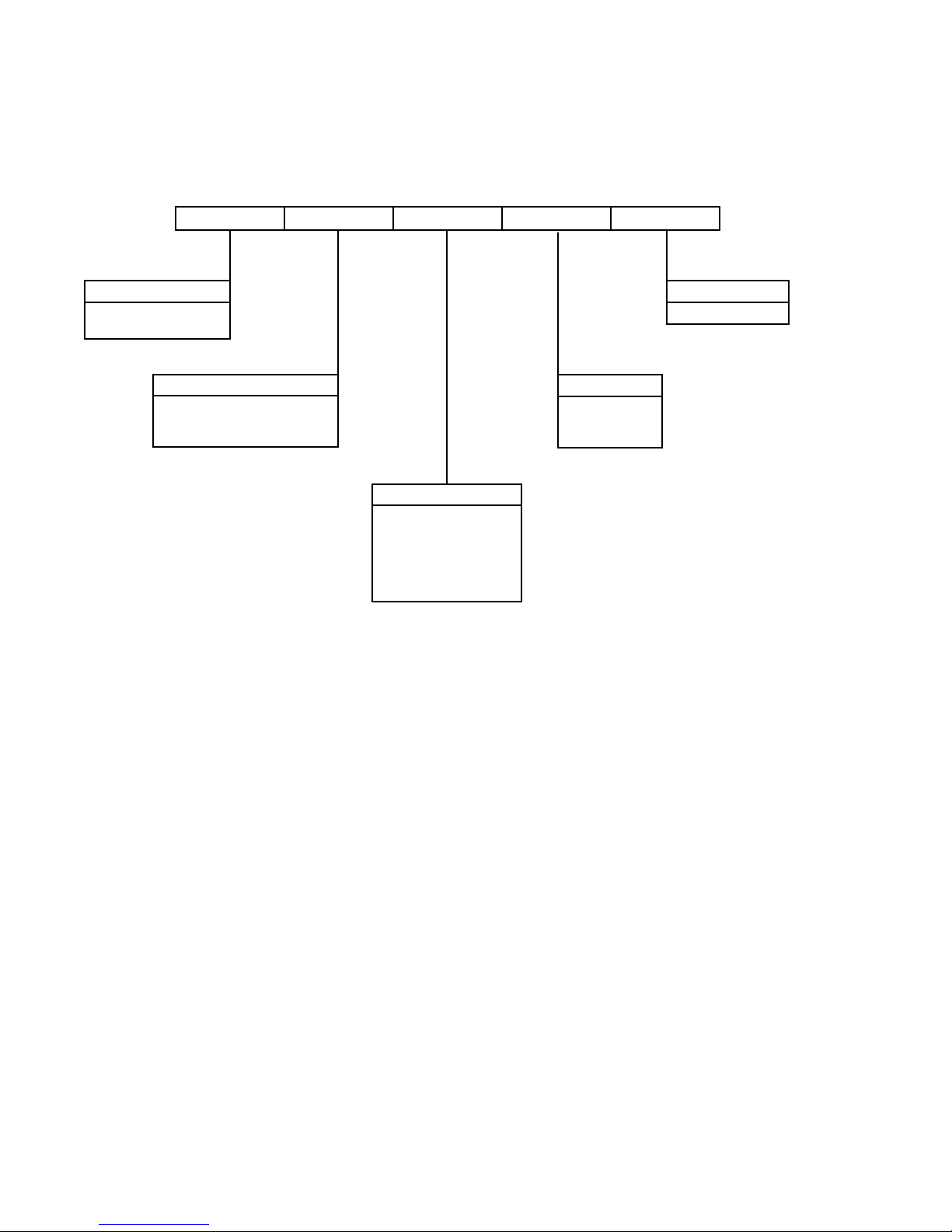
VFD NOMENCLATURE
1, 2, 3 4, 5, 6 7, 8, 9, 10, 11 12 13
VFD PTD 234HE 2 A
Product Category
VFD = VFD Program
Parameter Set
VFD Option
PTD = VAV with Transducer
2DS = Discrete 2 Speed
LAC = Low Ambient Condenser
Design Series
A = Current
Voltage
2 = 208-230/3/60
4 = 460/3/60
5 = 575/3/60
Motor Model Number
234HE = 1.5 HP Motor
235HE = 2.0 HP Motor
236HE = 3.0 HP Motor
237HE = 5.0 HP Motor
238HE = 7.5 HP Motor
239HE = 10.0 HP Motor
4
JOHNSON CONTROLS
Page 5

FORM 145.13-NO1
ISSUE DATE: 10/06/2016
TABLE OF CONTENTS
SECTION 1 - INSTALLATION ..................................................................................................................................7
Background ......................................................................................................................................................7
Factory Shipped ...............................................................................................................................................7
DSV Models .....................................................................................................................................................7
DSH Models .....................................................................................................................................................7
CSV Models .....................................................................................................................................................8
VAV Units ..........................................................................................................................................................8
Differential Pressure Transducer .............................................................................................................8
Discrete 2 Speed Fan Control .......................................................................................................................... 8
VFD Keypad ..................................................................................................................................................... 9
Installation ........................................................................................................................................................9
Install Grille Cover .......................................................................................................................................... 10
SECTION 2 - OPERATION ..................................................................................................................................... 11
Input/Output .................................................................................................................................................... 11
Parameter Tables ........................................................................................................................................... 11
Display ............................................................................................................................................................ 11
VFD Option Schematics ................................................................................................................................. 14
LIST OF FIGURES
FIGURE 1 - Warning Label On Unit/VFD For VAV with Pressure Transducer ..........................................................8
FIGURE 2 - Warning Label On Unit/VFD For Discrete 2 Speed Fan Control ...........................................................8
FIGURE 3 - VFD Keypad ..........................................................................................................................................9
FIGURE 4 - VFD Keypad and Ethernet Connector ................................................................................................... 9
FIGURE 5 - Connecting Negative and Positive Side Fittings .................................................................................. 10
FIGURE 6 - VFD Grille Cover ..................................................................................................................................10
FIGURE 7 - Input/Output Diagram .......................................................................................................................... 11
FIGURE 8 - Evaporator VFD Option for Discrete 2 Speed Wiring Schematic (575V/3PH/60Hz) ...........................14
FIGURE 9 - Evaporator VFD Option for Duct Static Pressure Wiring Schematic (208-230V/460V/3PH/60Hz)......15
FIGURE 10 - Evaporator VFD Option for Discrete 2 Speed Wiring Schematic (208-230V/460V/3PH/60Hz) .........15
LIST OF TABLES
TABLE 1 - VFD Factory Parameters for VAV Application 208/230 & 460 VAC (ABB ACS320) .............................. 11
TABLE 2 - Factory Parameters for 2 Speed Application 208/230 & 460 VAC (ABB ACS320) ................................12
TABLE 3 - Factory Parameters for 2 Speed Application 575 VAC (ABB ACS250) .................................................13
TABLE 4 - Drive Dependent Parameters Group 99 ................................................................................................ 13
JOHNSON CONTROLS
5
Page 6

FORM 145.13-NO1
ISSUE DATE: 10/06/2016
THIS PAGE INTENTIONALLY LEFT BLANK.
6
JOHNSON CONTROLS
Page 7

FORM 145.13-NO1
ISSUE DATE: 10/06/2016
SECTION 1 - INSTALLATION
DO NOT enter Setup mode when powering on the VFD.
There are two main VFD options: Differential Pressure Transducer and Discrete
2 Speed. Consult your unit's nameplate
to determine which you have, and refer
to the Differential Pressure Transducer
section and Discrete 2 Speed Fan Control section on page 8 for clarication
on these Fan Methods.
Do not change any parameters for Discrete 2 Speed Fan Control. For VAV units
using Differential Pressure Transducer,
parameters 4009 and 4011 will need
adjusted.
Prior to installing or servicing the unit,
ensure proper lockout/tagout (LOTO)
procedures are followed per OSHA
safety regulations (29 CFR 1910.147 and
29 CFR 1910.333). Failure to disconnect
power supply may result in electrical
shock or even death.
Always wait for at least 5 minutes after
disconnecting the power before servicing
the unit.
BACKGROUND
All D-Series and C-Series units 10 tons or larger will
have a Variable Frequency Drive (VFD) installed. The
VFDs are controlled by one of two Controlled Fan
Methods: Differential Pressure Transducer or Discrete
2 Speed Fan Control.
Refer to the nomenclature breakdown in
the appropriate DSV/DSH/CSV Installation, Operation, and Maintenance (IOM)
manual, as well as your unit's nameplate
to determine your unit's Controlled Fan
Method. The tenth digit of the nomenclature (ID Motor) will identify which
method your unit has.
1
Do not run evaporator fan motor below
30Hz, otherwise coil freeze-up and nuisance lock-outs may occur. Unit is factory
set to minimum 30 Hz output.
The unit does not carry a failsafe circuit
to bypass the VFD and run the evaporator
fan in the event of a VFD malfunction.
The unit does not carry a failsafe circuit bypass for
the evaporator fan in the event of a VFD malfunction.
During a VFD failure, the evaporator fan will become
non-operational and as long as there is a demand for
cooling, unit compressors will continue to run until the
low pressure safety switch trips.
FACTORY SHIPPED
Units 10 tons or larger ship with a VFD controller factory installed and wired in the evaporator (air handler)
corner post. See dimensional drawings in the IOM for
location.
DSV MODELS
DSV060 is factory assembled and requires no field
assembly. All other DSV units ship factory split (condenser and evaporator) and need to be assembled in the
field. Evaporator motor power conductors need to be
field connected to the distribution block on VFD. Connect low voltage wiring from VFD unit (10VDC) and
to the evaporator fan VFD relay (RVFD). The RVFD
relay acts as a switch to turn on the VFD. Connect two
1/4” Q.C. to common and normally open positions (red
wire to “C”; yellow wire to “NO”). The VFD switch
runs on 10VDC. See VFD Option Schematics on page
14 for connecting details.
Do not cross 24VAC and 10VDC wiring
on RVFD relay.
The VFD supplied with the unit allows the operator to
set the external static (0.0–2.5 "WC), as measured from
a supply duct location determined by field installer and/
or as per field specifications. The VFD will control the
frequency (speed) of the evaporator fan motor in order
to meet the desired external static (ESP) setpoint. The
VFD will control amps draw of the motor and will not
let the motor draw more than nominal amps.
JOHNSON CONTROLS
DSH MODELS
DSH units' VFD controller is factory wired and evaporator fan power conductors are factory wired to distribution block. Control wiring for field split applications
needs to be field provided and routed from condenser
to evaporator.
7
Page 8

SECTION 1 - INSTALLATION
FORM 145.13-NO1
ISSUE DATE: 10/06/2016
CSV MODELS
CSV units that are 10–20 tons are factory wired; no
field wiring is required. The 25-ton CSV unit ships
split, and field wiring of evaporator fan motor conductors to terminal block in electrical box is required.
Connect low voltage wiring from VFD unit (10VDC)
to the evaporator fan VFD relay RVFD (red wire to
“C”; yellow wire to “NO”). The RVFD relay acts as
a switch to turn on the VFD. The VFD switch runs on
10VDC. See VFD Option Schematics on page 14.
Do not cross 24VAC and 10VDC wiring.
VAV UNITS
Differential Pressure Transducer
VFD FACTORY PROGRAMMED
VFD PART #:
VFD APPLICATION:
DATE PROGRAMMED:
DRIVE FACTORY PROGRAMMED
SET PARAMETER 4009 & 4011 PRIOR TO START-UP
FOR TECHNICAL SUPPORT, CALL: 877-329-7430
FIGURE 1 - WARNING LABEL ON UNIT/VFD FOR
VAV WITH PRESSURE TRANSDUCER
VFD-PTD-236HE-2
VAV w/ PRESSURE TRANSDUCER
05/10/16
JOHNSON CONTROLS, AJAX, CANADA
STK-VFD
LD20871
Example: If the Supply Duct Static Pressure was
designed for 1.0 "WC, both Parameters 4009 and
4011 need set to 1. Adjust Parameters 4009 and
4011 up or down accordingly until the required
setpoint is achieved. Once the setpoint is adjusted,
please document Parameters 4009 and 4011 for
future reference.
The VFD setpoint should never be adjusted to be greater than the duct system's
or unit's maximum design pressures.
• The differential pressure transducer will provide a
signal to the VFD, and the VFD will control to the
setpoint parameters 4009 and 4011
• Only use the 24VDC from the VFD (Term. 9) to
the differential pressure transducer (Term. Exc.)
• Term. 2 from the VFD will be wired to the differential pressure transducer (Term. COM)
• The Term. OUT on the differential pressure transducer is not wired
• The jumper on the VFD, AI1, needs to be set to
4-20Ma
• The VFD is enabled by the Evaporator Fan VFD
Relay (RVFD)
• If the VAV option is not selected, the unit will
have Discrete 2 Speed Fan Control by default for
all units 10 tons or larger
DISCRETE 2 SPEED FAN CONTROL
VFD FACTORY PROGRAMMED
Units with a VAV option have a factory-wired differential pressure transducer mounted inside the VFD
control box. The transducer senses gage pressure (static) and converts this pressure difference to an analog
signal. The unit is wired for 4-20mA output from the
transducer.
Transducer comes with two 1/4-inch OD pressure fittings and accepts field provided 1/4-inch push-on tubing for lengths of up to 300 feet. The positive (HIGH)
and negative (LOW) pressure ports are indicated on
the transducer. Connect unit RETURN AIR tubing to
negative (LOW) fitting and SUPPLY AIR tubing to
positive (HIGH) fitting.
• Only on 208/230-460 VAC units; not on 575 VAC
• Parameters 4009 and 4011 are factory set at
0.5”WC.Theseareeldadjustedpointsthatneed
to be adjusted at start-up. These setpoints are
based upon system requirements.
8
VFD PART #:
VFD APPLICATION:
DATE PROGRAMMED:
DRIVE FACTORY PROGRAMMED
NO FIELD PROGRAMMING REQUIRED
FOR TECHNICAL SUPPORT, CALL: 877-329-7430
FIGURE 2 - WARNING LABEL ON UNIT/VFD FOR
DISCRETE 2 SPEED FAN CONTROL
VFD-2DS-236HE-2
2 DISCRETE SPEED
05/10/16
JOHNSON CONTROLS, AJAX, CANADA
STK-VFD
LD20872
The Discrete 2 Speed Fan Control is available on all
DSV and CSV units 10 tons or larger. For DSH units, it
is only available on the 10-ton units.
JOHNSON CONTROLS
Page 9

FORM 145.13-NO1
ISSUE DATE: 10/06/2016
SECTION 1 - INSTALLATION
Supply Fan VFD Sequence for 208/230-460 VAC units
(Discrete 2 Speed Fan Control):
Speed 1
• Supply fan only
OR
• Supply fan and compressor #1 running
• Factory set at 35 Hz (do not set lower than 35 Hz)
• Set at parameter 1202
• 24 VDC applied to terminal 12 of VFD
Speed 2
• Supply fan and compressors #1 and #2 are running
• Factory set at 60hz
• Set at parameter 1204
• 24 VDC applied to terminal 12 and 13 of VFD
Supply Fan VFD Sequence for 575 VAC units (only
Discrete 2 Speed Fan Control is used):
1
LD20860
FIGURE 3 - VFD KEYPAD
Speed 1
• Supply fan only
OR
• Supply fan and compressor #1 running
• Factory set at 35 Hz (do not set lower than 35 Hz)
• Set at parameter 1202
• 24 VDC applied to terminal 4 of VFD
Speed 2
• Supply fan and compressors #1 and #2 are running
• Factory set at 60hz
• Set at parameter 1204
• 24 VDC applied to terminal 4 and 6 of VFD
VFD KEYPAD
VFD requires a keypad to program the VFD. Once the
VFD is programmed, the keypad is not required in order to operate the unit. Each unit comes with factory
installed and programmed remote keypad and short
Ethernet clip-on connector. An Ethernet communication cable is not factory supplied. A single keypad can
be used to program multiple units. If needed, consult
with local Johnson Controls sales office to order additional keypads.
LD20861 LD20862
FIGURE 4 - VFD KEYPAD AND ETHERNET
CONNECTOR
INSTALLATION
Install a field supplied 1/4-inch push-on tube to the
return air side of the unit. Pass the tube through the
opening on the side of the corner post adjacent to the
VFD controls, and connect to the negative (LOW) side
fitting.
Install a field supplied Pitot tube in the supply duct as
required, run 1/4-inch push-on tube to the corner post
opening, and connect to the positive (HIGH) side fitting.
JOHNSON CONTROLS
9
Page 10

SECTION 1 - INSTALLATION
FIGURE 5 - CONNECTING NEGATIVE AND
POSITIVE SIDE FITTINGS
FORM 145.13-NO1
ISSUE DATE: 10/06/2016
INSTALL GRILLE COVER
When unit is wired and push-on tubing has been connected to transducer, attach the grille cover using the
screws provided, with angled blades point upward at
the top.
LD20863
Ensure the tubes are secure inside duct and firmly connected to transducer fitting, otherwise unit will not operate as intended.
LD20864
FIGURE 6 - VFD GRILLE COVER
10
JOHNSON CONTROLS
Page 11

FORM 145.13-NO1
ISSUE DATE: 10/06/2016
SECTION 2 - OPERATION
INPUT/OUTPUT
Transducer
(-COM)
Jumper set
to 4-20mA
Jumper required between 10, 11
FIGURE 7 - INPUT/OUTPUT DIAGRAM
Transducer
(+EXC) 24VDC
PARAMETER TABLES
In the parameter menu, set the following parameters
listed in the parameters tables in order to operate the
VFD controller correctly. For troubleshooting, check
that the parameters match.
DISPLAY
2
In AUTO MODE, the following parameters will be
displayed on control display:
1. 30–60Hz is the output frequency to the motor.
Minimum factory set frequency allowed is 30 Hz.
2. 0.0 to Nominal Motor Amps. Maximum amps
draw is factory set, and it is set to nominal amp
draw of motor used.
3. 0.0-2.5 "WC is the actual reading from the pressure transducer.
4. Located in the upper-right corner, the setpoint
value is displayed. It goes from 0% to 100%. That
is the actual setpoint for the controller. Setpoint
can be 0%, which is 0.0 "WC or 100%, which is
2.5 "WC.
Example: 20% corresponds to 0.5 "WC setpoint.
Setpoint can be updated using parameter 4011.
TABLE 1 - VFD FACTORY PARAMETERS FOR VAV APPLICATION 208/230 & 460 VAC (ABB ACS320)
PARAMETER DESCRIPTION VALUE
GROUP 99: START-UP DATA
9901 LANGUAGE 0: (ENGLISH)
9902 APPLICATION MACRO 1: (HVAC DEFAULT)
9905 MOTOR NOMINAL VOLTAGE MOTOR NAMEPLATE
9906 MOTOR NOMINAL CURRENT MOTOR NAMEPLATE
9907 MOTOR NOMINAL FREQUENCY MOTOR NAMEPLATE
9908 MOTOR NOMINAL SPEED MOTOR NAMEPLATE
9909 MOTOR NOMINAL POWER MOTOR NAMEPLATE
GROUP 10
1003 DIRECTION 1: (FORWARD)
GROUP 11
1102 EXT1/EXT2/SELECTION 7: (EXT2)
1103 REF1 SELECT 0: (KEYPAD)
GROUP 13
1301 MINIMUM AI1 0%
GROUP 16
1601 RUN ENABLE 1: (DI1)
1608 START ENABLE 1 0: (NOT SELECTED)
1611 PARAMETER VIEW 3: (LONG VIEW)
JOHNSON CONTROLS
11
Page 12

SECTION 2 - OPERATION
FORM 145.13-NO1
ISSUE DATE: 10/06/2016
TABLE 1 - VFD FACTORY PARAMETERS FOR VAV APPLICATION 208/230 & 460 VAC (ABB ACS320) (CONT'D)
PARAMETER DESCRIPTION VALUE
GROUP 20
2003 MAX CURRENT DRIVE DEPENDENT
2007 MINIMUM FREQUENCY 30 HZ
GROUP 34
3403 SIGNAL 1 MAX 60 HZ
3405 OUTPUT 1 UNIT 3: (HZ)
3407 OUTPUT 1 MAX 60
3416 SIGNAL 3 MIN 20
3419 OUTPUT 3 UNIT 59: (in WC)
3421 OUTPUT 3 MAX 2.5
GROUP 40
4006 UNITS 59: (in WC)
4007 UNIT SCALE 2
4008 0% VALUE 0
4009 100% VALUE FIELD SET (DEFAULT 0.5)
4010 SETPOINT SELECTION 19: (INTERNAL)
4011 INTERNAL SETPOINT FIELD SET (DEFAULT 0.5)
4012 SETPOINT MIN 0
4013 SETPOINT MAX 100
4014 FBK SELECT 1: (ACT1)
4016 ACT1 INPUT 1: (AI1)
4018 ACT1 MIN 20
4019 ACT1 MAX 100
TABLE 2 - FACTORY PARAMETERS FOR 2 SPEED APPLICATION 208/230 & 460 VAC (ABB ACS320)
PARAMETER DESCRIPTION VALUE
GROUP 99
9901 LANGUAGE 0: (ENGLISH)
9902 APPLICATION MACRO 1: (HVAC DEFAULT)
9905 MOTOR NOMINAL VOLTAGE MOTOR NAMEPLATE
9906 MOTOR NOMINAL CURRENT MOTOR NAMEPLATE
9907 MOTOR NOMINAL FREQUENCY MOTOR NAMEPLATE
9908 MOTOR NOMINAL SPEED MOTOR NAMEPLATE
9909 MOTOR NOMINAL POWER MOTOR NAMEPLATE
GROUP 10
1002 EXT2 COMMANDS 0: (NOT SELECTED)
GROUP 11
1103 REF 1 SELECT 0: (KEYPAD)
1106 REF 2 SELECT 0: (KEYPAD)
GROUP 12
1201 CONSTANT SPEED SEL 7: (DI1,DI2)
1202 CONSTANT SPEED 1 35 (*See Note)
1204 CONSTANT SPEED 2 60
12
JOHNSON CONTROLS
Page 13

FORM 145.13-NO1
ISSUE DATE: 10/06/2016
SECTION 2 - OPERATION
TABLE 2 - FACTORY PARAMETERS FOR 2 SPEED APPLICATION 208/230 & 460 VAC (ABB ACS320) (CONT'D)
PARAMETER DESCRIPTION VALUE
GROUP 16
1608 START ENABLE 1 1: (DI1)
1611 PARAMETER VIEW 3: (LONG VIEW)
GROUP 20
2003 MAX CURRENT DRIVE DEPENDENT
GROUP 34
3403 SIGNAL 1 MAX 60
3405 OUTPUT 1 UNIT 3: (HZ)
3407 OUTPUT 1 MAX 60
3408 SIGNAL 2 PARAMETER NOT SELECTED
3415 SIGNAL 3 PARAMETER NOT SELECTED
*Note: If only one speed fan operation is wanted, adjust to 60.
TABLE 3 - FACTORY PARAMETERS FOR 2 SPEED APPLICATION 575 VAC (ABB ACS250)
PARAMETER DESCRIPTION VALUE
GROUP 99
9902 APPLICATION MACRO 8
9905 MOTOR NOMINAL VOLTAGE MOTOR NAMEPLATE
9906 MOTOR NOMINAL CURRENT MOTOR NAMEPLATE
9907 MOTOR NOMINAL FREQUENCY MOTOR NAMEPLATE
9908 MOTOR NOMINAL SPEED MOTOR NAMEPLATE
GROUP 11
1103 PRIMARY COMMAND 0: TERMINAL CONTROL
GROUP 12
1202 CONSTANT SPEED 1 0
1203 CONSTANT SPEED 2 35 (* See Note)
1204 CONSTANT SPEED 3 0
1205 CONSTANT SPEED 4 60
*NOTE: If only one speed fan operation is wanted, adjust to 60.
2
TABLE 4 - DRIVE DEPENDENT PARAMETERS GROUP 99
VFD PROGRAM
PART #
VFD-PTD-234HE-2
VFD-PTD-234HE-4 ACS320-03U-03A3-4 460/3/60 2.20
VFD-PTD-235HE-2
VFD-PTD-235HE-4 ACS320-03U-04A1-4 460/3/60 2.90
VFD-PTD-236HE-2
VFD-PTD-236HE-4 ACS320-03U-05A6-4 460/3/60 4.20
VFD-PTD-237HE-2
VFD-PTD-237HE-4 ACS320-03U-08A8-4 460/3/60 6.60
VFD-PTD-238HE-2
VFD-PTD-238HE-4 ACS320-03U-12A5-4 460/3/60 9.70
JOHNSON CONTROLS
AJAX MOTOR
(BALDOR MOTOR)
MODEL #
MTR-234HE
(EM3154T)
MTR-235HE
(EM3157T)
MTR-236HE
(EM3211T)
MTR-237HE
(EM3218T)
MTR-238HE
(EM3311T)
ABB VFD MODEL # VOLTAGE HP
ACS320-03U-07A4-2 208-230/3/60
ACS320-03U-07A4-2 208-230/3/60
ACS320-03U-10A8-2 208-230/3/60
ACS320-03U-19A4-2 208-230/3/60
ACS320-03U-26A8-2 208-230/3/60
1.50
2.00
3.00
5.00
7.50
MOTOR
NOMINAL
CURRENT FLA
4.50
5.80
8.50
14.00
20.40
MOTOR
NOMINAL
SPEED RPM
1755
1750
1765
1750
1770
13
Page 14

SECTION 2 - OPERATION
TABLE 4 - DRIVE DEPENDENT PARAMETERS GROUP 99 (CONT'D)
VFD PROGRAM
PART #
VFD-2DS-234HE-2
VFD-2DS-234HE-4 ACS320-03U-03A3-4 460/3/60 2.20
VFD-2DS-234HE-5
VFD-2DS-235HE-2
VFD-2DS-235HE-4 ACS320-03U-04A1-4 460/3/60 2.90
VFD-2DS-235HE-5
VFD-2DS-236HE-2
VFD-2DS-236HE-4 ACS320-03U-05A6-4 460/3/60 4.20
VFD-2DS-236HE-5
VFD-2DS-237HE-2
VFD-2DS-237HE-4 ACS320-03U-08A8-4 460/3/60 6.60
VFD-2DS-237HE-5
VFD-2DS-238HE-2
VFD-2DS-238HE-4 ACS320-03U-12A5-4 460/3/60 9.70
VFD-2DS-238HE-5
AJAX MOTOR
(BALDOR MOTOR)
MODEL #
MTR-234HE
(EM3154T)
MTR-534HE
(EM3154T-5)
MTR-235HE
(EM3157T)
MTR-535HE
(EM3157T-5)
MTR-236HE
(EM3211T)
MTR-536HE
(EM3211T-5)
MTR-237HE
(EM3218T)
MTR-537HE
(EM3218T-5)
MTR-238HE
(EM3311T)
MTR-538HE
(EM3311T-5)
ABB VFD MODEL # VOLTAGE HP
ACS320-03U-07A4-2 208-230/3/60
1.50
ACS250-03U-03A1-6 575/3/60 1.80
ACS320-03U-07A4-2 208-230/3/60
2.00
ACS250-03U-03A1-6 575/3/60 2.30
ACS320-03U-10A8-2 208-230/3/60
3.00
ACS250-03U-04A1-6 575/3/60 3.40
ACS320-03U-19A4-2 208-230/3/60
5.00
ACS250-03U-06A5-6 575/3/60 5.30
ACS320-03U-26A8-2 208-230/3/60
7.50
ACS250-03U-09A0-6 575/3/60 7.50
MOTOR
NOMINAL
CURRENT FLA
FORM 145.13-NO1
ISSUE DATE: 10/06/2016
MOTOR
NOMINAL
SPEED RPM
4.50
1755
5.80
1750
8.50
1765
14.00
1750
20.40
1770
VFD OPTION SCHEMATICS
FIGURE 8 - EVAPORATOR VFD OPTION FOR DISCRETE 2 SPEED WIRING SCHEMATIC (575V/3PH/60HZ)
14
LD20866
JOHNSON CONTROLS
Page 15

FORM 145.13-NO1
ISSUE DATE: 10/06/2016
3
FIGURE 9 - EVAPORATOR VFD OPTION FOR DUCT STATIC PRESSURE WIRING SCHEMATIC
(208-230V/460V/3PH/60HZ)
LD20867
FIGURE 10 - EVAPORATOR VFD OPTION FOR DISCRETE 2 SPEED WIRING SCHEMATIC
(208-230V/460V/3PH/60HZ)
JOHNSON CONTROLS
LD20868
15
Page 16

P.O. Box 1592, York, Pennsylvania USA 17405-1592 800-861-1001 Subject to change without notice. Printed in USA
Copyright © by Johnson Controls 2016 www.johnsoncontrols.com ALL RIGHTS RESERVED
Form 145.13-NO1 (1016)
Issue Date: October 6, 2016
New Release
 Loading...