

Johnson Controls VG1600 Series, VA9905-KGA-2, VA9905 Series, VA9905-KGA-1 Installation Instructions Manual
Page 1
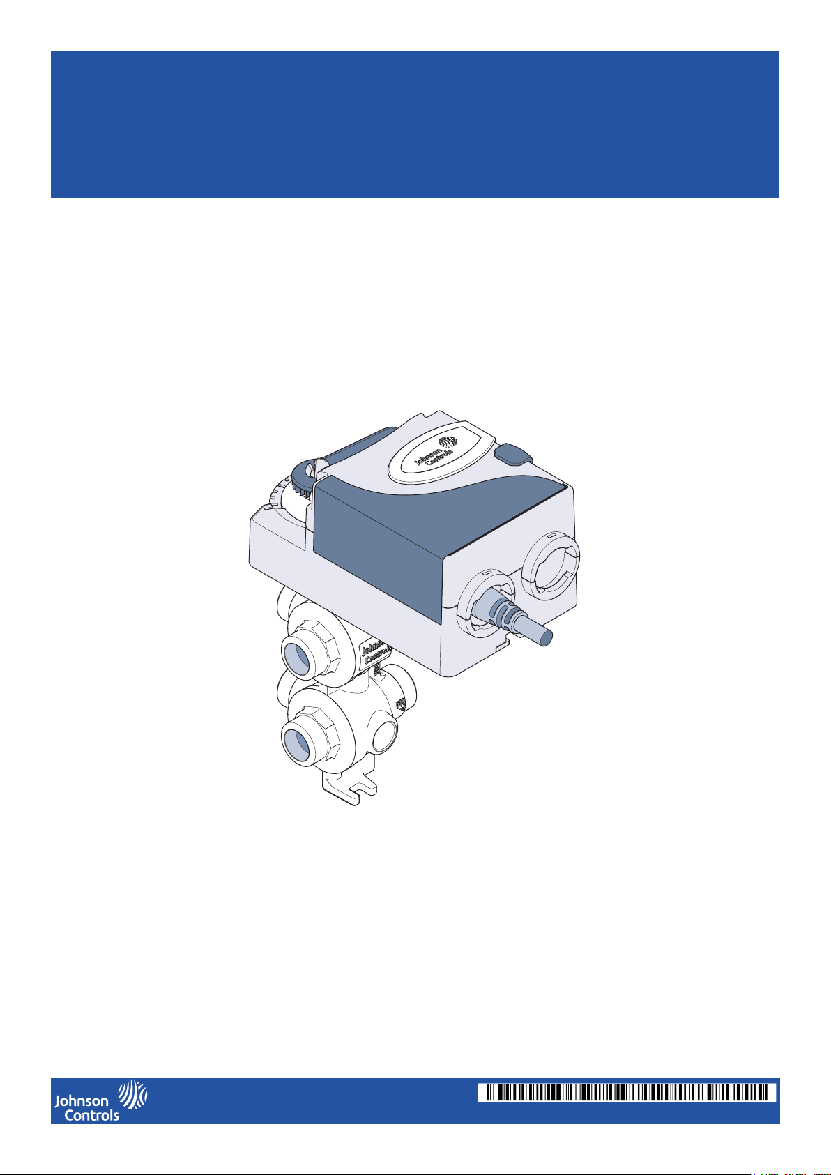
VA9905 Actuator and
VG1600 Series Six-Way Valves
Installation Instructions
14-88360-03206, Rev. -
Page 2

Contents
Compliance Information............................................................................1
About This Document ............................................................................... 1
Accessories ..............................................................................................1
Support Information ..................................................................................1
Parts Included...........................................................................................2
Tools Required..........................................................................................2
Flow Disk Set............................................................................................3
Installing the Six-Way Valve to a System .................................................4
Clearance Required to Install an Actuator ................................................4
Attaching the Actuator to the Six-way Valve ............................................. 5
Setting the DIP Switches ..........................................................................6
Wiring the Actuator ................................................................................... 6
Manual Override and Flow Direction ........................................................7
VA9905 Technical Specications .............................................................. 8
VG1600 Valve Series Technical Specications ........................................9
Compliance Information
IMPORTANT: Use this VA9905 Actuator only to control equipment under normal operating conditions.
Where failure or malfunction of the VA9905 Actuator could lead to personal injury or property damage to the controlled equipment or other property, additional precautions must be designed into the control system. Incorporate
and maintain other devices, such as supervisory or alarm systems or safety or limit controls, intended to warn of or
protect against failure or malfunction of the device.
IMPORTANT : Utiliser ce [nom complet de l’appareil] uniquement en tant que dispositif de contrôle de
fonctionnement. Lorsqu’une défaillance ou un dysfonctionnement du [nom abrégé de l’appareil] risque de
provoquer des blessures ou d’endommager l’équipement contrôlé ou un autre équipement, la conception du
système de contrôle doit intégrer des dispositifs de protection supplémentaires. Veiller dans ce cas à intégrer de
façon permanente d’autres dispositifs, tels que des systèmes de supervision ou d’alarme, ou des dispositifs de
sécurité ou de limitation, ayant une fonction d’avertissement ou de protection en cas de défaillance ou de
dysfonctionnement du [nom abrégé de l’appareil].
About This Document
This guide describes how to install and congure the VA9905 Actuator and Six-Way Valve. The procedures in this
guide must be completed sequentially, as they are listed.
Accessories (order separately)
Code Number Name Description
VG1600-01 Wall Mounting Bracket Kit Provides a mounting bracket for the VA9905 Actuator.
VG1600-02 Flow Disk Kit Provides replacement ow disks.
VG1600-03 Insulation Shell Kit Provides valve insulation.
VG1600-04 Sweat Union Fitting Kit Provides sweat union ttings.
M9300-100 Conduit Adapter Kit (5 per kit) Provides a conduit adapter that protects the input cable.
Support Information
European Single Point of Contact: NA/SA Single Point of Contact: APAC Single Point of Contact:
Johnson Controls Johnson Controls Johnson Controls
Westendhof 3 507 E Michigan Street C/O Controls Product Management
45143 Essen Milwaukee WI 53202 No. 22 Block D, New District
Germany USA Wuxi Jiangsu Province 214142
China
1
14-88360-03206, Rev. A
Page 3
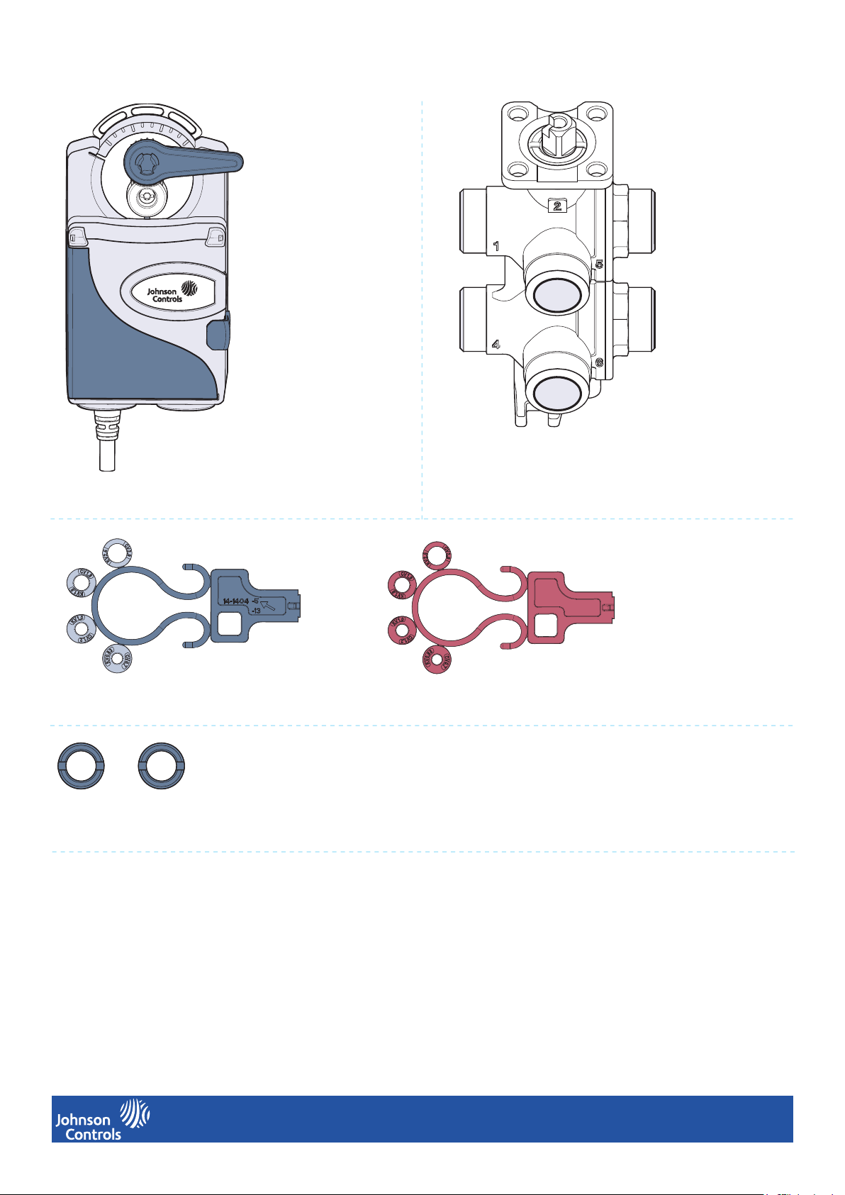
Parts Included
VA9905 Actuator
Two Flow Disk Sets
Two Ring Nuts
VG1600 Series Valve
Tools Required
• 8mm (5/16 in) slotted screwdriver
or a TORX® T-20 driver
2
14-88360-03206, Rev. A
Page 4

Flow Disk Set
Disassembly
1
Disk Storage
1
2
2
3
3
4
Installation
Note: Use blue restriction disks with cold water and red disks with hot water only.
Flow restriction disks have markings that indicate the rate of restriction they provide.
Using the supplied restriction disks, you can set the following ow rates in ports 4 and 6:
Disk Opening Smallest Small Medium Largest No disk
CV 0.7 1.2 1.9 2.9 3.9
Kv 0.63 1.0 1.6 2.5 3.3
1
2
3
3
14-88360-03206, Rev. A
Page 5

Installing the Six-way Valve to a System
The diagram below illustrates the input and output ows for the 6-way valve. Use this diagram as a guide on how to
install the 6-way valve to your system.
Note: Valve port 2 must only be used as coil supply. Valve port 3 must only be used as coil return.
Valve port Description Analog Input Control
1
5
1 Source 1 supply Controlled by the gray wire
2 Coil supply
3 Coil return
4 Source 1 return Controlled by the gray wire
4
2
6
5 Source 2 supply Controlled by the orange wire
6 Source 2 return Controlled by the orange wire
Note: Source 1 and 2 can be used for hot or cold water.
3
Clearance Required to Install an Actuator
The diagrams below illustrate the clearance required to install an actuator to the VG1600 Valve Series.
89 mm
(3 - 1/2 in.)
100 mm (3 -15/16 in.)
75 mm
(2 - 15/16 in.)
150 mm (5 - 29/32 in.)66 mm (2 - 19/32 in.)
114 mm
(4 - 31/64 in.)
4
14-88360-03206, Rev. A
Page 6

Attaching the Actuator to the Six-Way Valve
Note: The VA9905 Actuator ts VG1600 series valves only.
1
Use the valve key to adjust the valve stem
to a 90° angle, away from the curved section.
2
Press the manual override button on the actuator.
4
Ensure the valve stem is aligned as shown.
3
Move the actuator lever to the extreme right position.
5
Align the top of the 6-way valve to the plate
at the back of the actuator.
Use a slotted screwdriver or a TORX® T-20 driver to
tighten the actuator screw to the 6-way valve. Tighten
to a torque of 0.9 to 1.4 Nm (8 to 12 lb-in).
5
14-88360-03206, Rev. A
Page 7

Setting the DIP Switches
!
!
1
AC 24 V
DC 0
(2)
.10V
GRY
BLK
RED
ORN
1
4
2
3
Remove the dip switch cover by placing your
nger behind it and pulling it toward yourself.
2
7
8
6
45
3
1
2
OFF
ON
45
6
3
AC 24 V
BLK
1
7
8
1
45
7
3
2
6
8
DC 0
(2)
.10V
GRY
RED
ORN
4
2
3
You now have access to the actuator dip switches.
1
2
OFF
ON
If the controller output signal range is:
• 2 to 10 V: Push dip switch 1 to the ON position.
-or-
• 0 to 10 V: Push dip switch 1 to the OFF position.
Wiring the Actuator
Risk of electric shock.
Disconnect the power supply before making electrical connections to avoid electric shock.
Risque de décharge électrique.
Débrancher l’alimentation avant de réaliser tout raccordement électrique an d’éviter tout risque de décharge électrique.
Wire the VA9905 Actuator as described in the table below:
CAUTION
ATTENTION
Wire Color Input
Black Com 24 V AC\DC
Red ~(+)
Gray (Source 1 control) Y1 DC 0(2)...10 V
Orange (Source 2 control) Y2
6
14-88360-03206, Rev. A
Page 8

Manual Override and Flow Direction
x
xx
x
xx
x
The manual override lever is used to indicate which ports are in use.
In the absence of power to the actuator, manually set the pointer to the desired position to regulate the ow of the
valve.
Note: The setup procedure described in the Attaching the Actuator to a Six-way Valve section sets ports 1 and 4 to full
ow.
Note: The ball valve and actuator pointer rotate in opposite directions.
The following illustrations indicate lever position and ow:
Full Flow on ports 5 and 6 No Flow Full Flow on Ports 1 and 4
When no actuator is installed, use the following positions of the stem to set the ow of the valve:
Note: The cuts on the valve stem indicate the ports inside the valve.
Full Flow on Ports 5 and 6 No Flow Full Flow on Ports 1 and 4
7
14-88360-03206, Rev. A
Page 9

VA9905 Actuator Technical Specications
Product description VA9905-KGA-1: Proportional mode, VA9905-KGA-2: Proportional mode
Power requirements AC 24 V ±20% at 50/60 Hz, Class 2 (North America) or SELV (Europe), 5.2 VA Running;
DC 24 V ±10% Class 2 (North America) or SELV (Europe), 1.1 W Running.
Transformer sizing
requirements
Input signal/adjustments 0 (2) to 10 VDC or 0 (4) to 20 mA with eld furnished 500 ohm 1/4 W resistor
Control impedance 100k ohm
Rotation rate 1.5 ° per second
Cycles 60,000 full stroke cycles; 2,500,000 repositions
Audible noise <35 dBA at 1 m (39-13/32 in.)
Electrical connections -1 halogen-free
Conduit connections 13 mm NPSM (1/2 in.) threaded conduit connectors with M9300-100 conduit
Ambient conditions Operating: 0 to 60°C (32 to 140°F), 90% RH, noncondensing
Enclosure IP54/NEMA 5
Dimensions VA9905 Actuator: Width: 89 mm (3-1/2 in.), Height: 74 mm (2-15/16 in.), Length: 170
Shipping weight Valves:
≥6 VA
-2 plenum-rated
1.2 m (48 in.) halogen free cable with
0.82 mm² (18 AWG) conductors and
6 mm (0.25 in.) ferrule ends
Storage: -40 to 85°C (-40 to 185°F), 95% RH, noncondensing
mm (5-11/16 in.)
• VG1611AF: 0.7 Kg (1.55 lbs)
• VG1641AF: 0.8 Kg (1.85 lbs)
• VG1671AF: 1 Kg (2.20 lbs)
3.05 m (120 in.) UL 444 type CMP plenum
rated cable with 0.75 mm² (19 AWG cable)
conductors and 6 mm (0.25 in.) ferrule ends
Actuator
• VA9905: 0.8 Kg (1.75 lbs)
Compliance United States: UL Listed, CCN XAPX, File E27734; to UL 60730-1: Automatic Electrical
Controls for Household and Similar Use, Part 1; and UL 60730-2-14: Part 2, Particular
Requirements for Electric Actuators. Plenum Rated (UL 2043). Suitable for use in Other
Environmental Air Space (Plenum) in accordance with section 300.22 (c) of the National
Electrical Code.
Canada: UL Listed, CCN XAPX7, File E27734; to CAN/CSA E60730-1:02: Automatic
Electrical Controls for Household and Similar Use, Part 1; and CAN/CSA-E60730-2-14,
Particular Requirements for Electric Actuators.
Europe:
CE Mark—Johnson Controls declares that this product is in compliance with the
essential requirements and other relevant provisions of the EMC Directive.
IEC 60730-1: Automatic Electrical Controls for Household and Similar Use, Part 1:
General Requirements and IEC 60730-2-14, Automatic Electrical Controls for Household
and Similar Use; Part 2—Particular Requirements for Electric Actuators
Australia and New Zealand: RCM—Australia/NZ Emissions Compliant
The performance specications are nominal and conform to acceptable industry standard. For application at conditions beyond
these specications, consult the local Johnson Controls ofce. Johnson Controls shall not be liable for damages resulting from
misapplication or misuse of its products.
8
14-88360-03206, Rev. A
Page 10
VG1600 Valve Series Technical Specications
Total operation angle 270°
Sequence 1 0...>90°
Dead band >90…<180°
Sequence 2 >180…270°
Characteristic curve Linear
ID 10,5 mm
Fluid type Water, glycol solutions (max 50%) for HVAC applications
Fluid temperature 5 to 95 °C (41 to 203 °F)
Nominal pressure PN16 (232 psi)
Close off pressure 350 kPa (50 psi)
Max. differential pressure 240 kPa (35 psi)
Range ability 100:1
Max. Cv (Kv) 3.3 (3.8) - ½’’ pipe size
Connections • Valve Body with Male BSPP Thread (external)
• Valve Body with Female NPT Thread (internal
• Sweat Union Fitting kit
Flow coefcient Flow control disk
Leakage rate A, 100,000 cycles in iron-oxide contaminated water and air-bubble-tight (EN 12266-1)
Water quality Iron-oxide contaminated water (900ppm)
Maintenance Maintenance Free
Warranty Minimum 5 years to our customer
The performance specications are nominal and conform to acceptable industry standard. For application at conditions beyond
these specications, consult the local Johnson Controls ofce. Johnson Controls shall not be liable for damages resulting from
misapplication or misuse of its products.
9
14-88360-03206, Rev. A
 Loading...