

Page 1
Installation Instructions V48
Issue Date May 1, 2002
V48 Series 3-Way Pressure-Actuated Water-Regulating Valves
With Union Fittings
Application
IMPORTANT: The V48 Series 3-Way
Pressure-Actuated Water-Regulating Valves are
intended to control water flow under normal
equipment operating conditions. Where failure or
malfunction of a V48 valve could lead to an
abnormal operating condition that could cause
personal injury or damage to the equipment or other
property, other devices (limit or safety controls) or
systems (alarm or supervisory) intended to warn of,
or protect against, failure or malfunction of the V48
valve must be incorporated into and maintained as
part of the control system.
The V48 direct-acting models open on an increase in
pressure. The V48 valves with Union fittings are
available in 1/2-in. through 1-1/4-in. sizes and may be
used with standard non-corrosive refrigerants.
Installation
IMPORTANT: If these valves are installed on
equipment that contains hazardous or regulated
materials, such as refrigerants or lubricants, the
installer and user should observe all regulations
governing the handling and containment of those
materials.
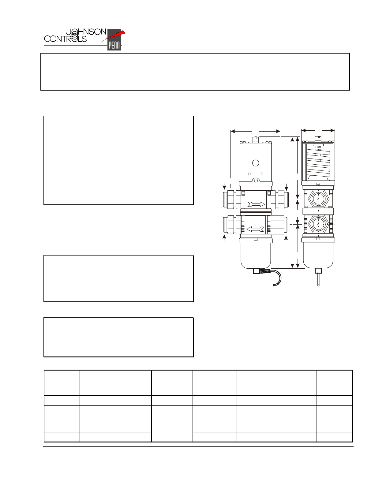
Dimensions
Port 1
Port 3
A
C
Port 2
Plugged
Pressure connection and capillary
as specified.
D
E
F
B
Figure 1: V48 Valve Dimensions for Models With
Union Fittings
IMPORTANT: It is recommended to apply a
non-hardening, pliable sealant (Loctite® 567 or
equivalent) to the face of the copper tailpiece to
compensate for slight piping misalignments and
surface imperfections on union ends.
Table 1: V48 Valve Dimensions, in. (mm)
Product
Code
Number
V48AJ-2C 1/2 in. 3-1/2 (89) 1-13/16 (47) 7-15/16 (200) 3-3/4 (96) 1-1/2 (38) 2-5/8 (67)
V48EK-2C 3/4 in. 3-13/16 (97) 2 (52) 8-9/16 (218) 4-3/16 (106) 1-3/4 (44) 2-5/8 (67)
V48AL-2C 1 in. 5-1/8 (130) 2-5/8 (67) 11-5/8 (295) 5-15/16 (151) 2 (51)
V48AM-2C 1-1/4 in. 5-3/16 (131) 2-5/8 (67) 12-7/16 (316) 6-3/16 (157) 2-3/8 (60) 3-7/8 (99)
© 2002 Johnson Controls, Inc.
Part No. 24-7664-2160, Rev. A www.johnsoncontrols.com
Nominal
Valve
Size
AB C D EF
3-11/16
(94)
1
Page 2
Manually Flushing the Valve
Manually flush the valve and fluid piping before and
after installing, repairing, or replacing a valve to
remove filings, chips, or other foreign matter. Insert
screwdrivers under both sides of the valve spring
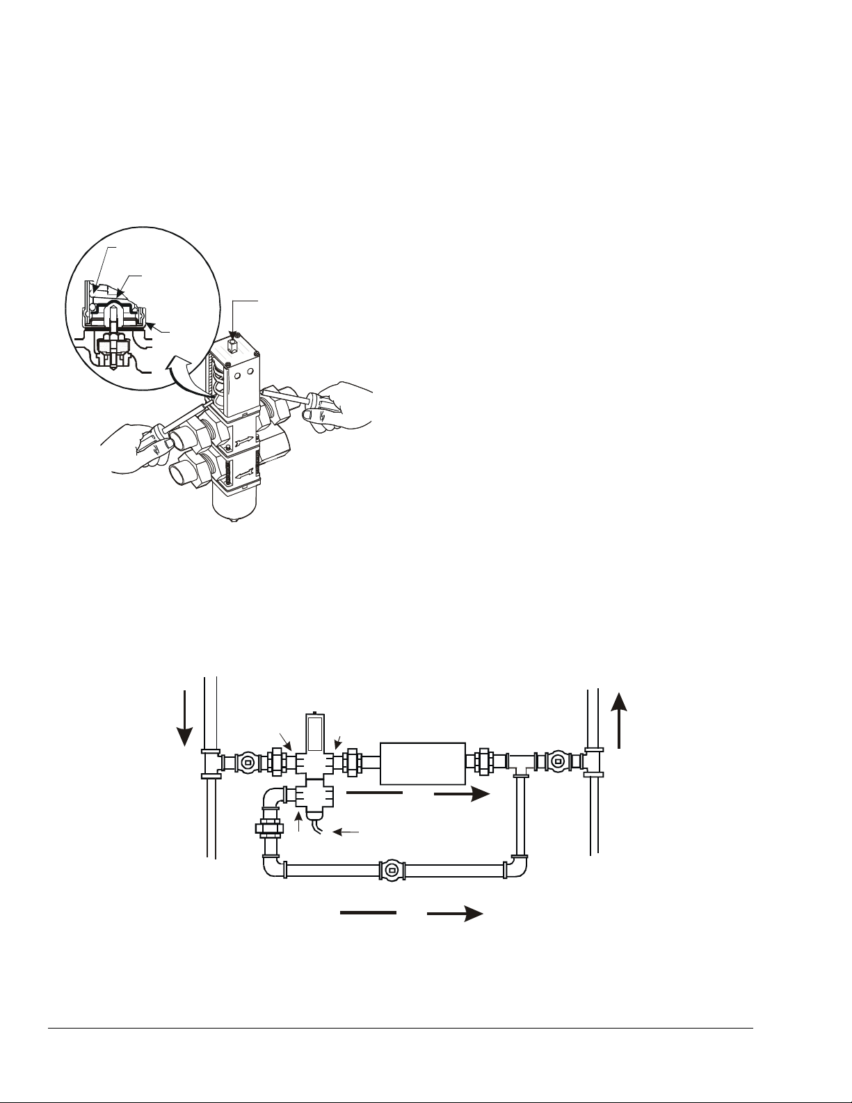
guide and lift upwards to flush the valve. See Figure 2.
Manual flushing does not affect valve adjustment.
Range
Spring
Val ve Sp r i ng
Guide
Range Adjustment
Top
Retainer
Screw
Insert screwdrivers
underneath the valve
spring guide.
Figure 2: Manual Flushing
Do not mount the valve in any position other than
vertical unless specified by the manufacturer of the
equipment on which the valve is installed. Follow the
manufacturer's installation instructions.
Install the V48 valve as shown in Figure 3. Port 1 is for
the inlet connection from the tower. Port 2 is for the
outlet connection to the condenser inlet. Port 3 is the
bypass connection.
Install the valve on the inlet side of the condenser. If it
is necessary to keep the condenser flooded with
water, install the valve on the outlet side of the
condenser.
If the system is located in an area with high ambient
temperatures, refrigerant head pressures may remain
high enough during Off cycles to prevent the valve
from closing completely. In such instances, the
opening point pressure of the valve should be raised
just enough to cause the valve to stop flow to the
condenser during compressor standby periods.
When used on a single condenser system, adjust the
balancing valve in the bypass with the compressor
shut off and the tower pump operating. Adjust the
balancing valve so that the amount of water through
the bypass is just sufficient to provide the minimum
recommended nozzle pressure. See Figure 3.
Location Considerations
Install the valve vertically with the range adjustment
screw on the top, and the bellows and pressure
connection line on the bottom to allow oil and
refrigerant to drain away from valve bellows.
From Cooling Tower
V48 Valve
Port 1
Port 3
To Other
Condensers
(if used)
Bypass
Port 2
Balancing Valve
Figure 3: Recommended Piping Arrangement for V48 Valves
On a multiple condenser system, adjust the balancing
valves in the bypasses evenly with the compressors
Off and the tower pump On. The total flow through all
the bypasses should be just sufficient to provide the
minimum recommended nozzle pressure.
Port 1 = Inlet (From Cooling Tower)
Port 2 = To Condenser
Port 3 = Bypass Condenser to
Cooling Tower
Condenser
Flow
From Bellows to
Refrigerant Pressure Tap
Connection
Flow
To Cooling Tower
From Other
Condensers
(if used)
2 V48 Series 3-Way Pressure-Actuated Water-Regulating Valves With Union Fittings Installation Instructions
Page 3
Pressure Connections
!
WARNING: Risk of Personal Injury.
To avoid possible personal injury, shut off the liquid
supply and relieve the pressure before servicing the
valve.
Connect the refrigerant-side flare connector to the
appropriate high-side pressure tap point. If additional
capillary tubing is necessary, use 1/4-in. tradesize
copper tubing.
Follow the guidelines below when making pressure
connections:
• Use Pressure Tap Points Located on the Top
Side of the Refrigerant Lines
This reduces the possibility of oil, liquids, or
sediment accumulating in the pressure connection
line or valve bellows, which could cause valve
malfunction.
•
Avoid Sharp Bends in the Capillary Tubes
Sharp bends can weaken or kink capillary tubes,
which may result in refrigerant leaks or
restrictions.
•
Allow for Slack in the Capillary Tubes to
Dampen Vibration
Mechanical vibration can weaken or damage the
capillary tubes.
•
Avoid Contact Between the Capillary Tubing
and Sharp or Abrasive Objects
Vibration or rubbing of sharp or abrasive objects in
contact with capillary tubes can cause leaks.
•
Coil and Secure Excess Capillary Tubing Away
from Contact with Sharp or Abrasive Objects
or Surfaces
Carefully loop any excess capillary tube into
smooth, circular coils (minimum 2 in. [5 cm]
diameter). Securely fasten the coiled capillary
tube.
•
Do Not Overtighten Flare Nuts on Pressure
Connection Line Fittings
Overtightening flare connections may damage the
threads and result in refrigerant leaks. Do not
exceed 9 lb⋅ft (12 N⋅m) of torque when tightening
brass flare connections.
• Avoid Severe Pressure Pulsation at Pressure
Tap Points
Install pressure connection lines to pressure tap
points away from the compressor discharge to
minimize the effects of pressure pulsation from
reciprocating compressors.
Table 2: Pressure Specifications for V48 Series Valves with Union Fittings
Product
Code
Number
Nominal
Valve
Size
Maximum
Refrigerant
Pressure at
Bellows
V48AJ-2C 1/2 in. 320 psi
(2206 kPa)
V48EK-2C 3/4 in. 370 psi
(2551 kPa)
V48AL-2C 1 in.
V48AM-2C 1-1/4 in.
320 psi
(2206 kPa)
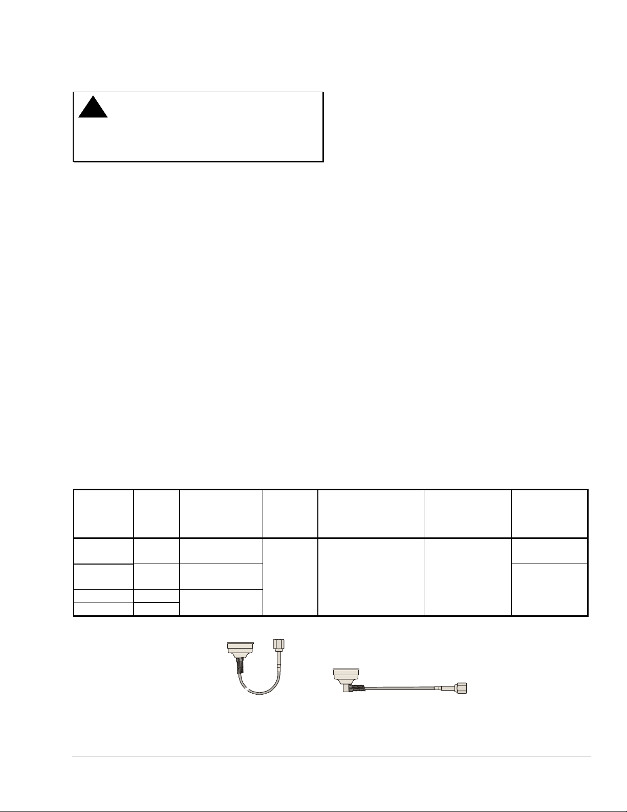
1/4-in. SAE Female Flare Connector
(Includes Valve Stem Depressor.)
Maximum
Water
Pressure
150 psi
(1034 kPa)
Style 45
Copper Capillary with
Opening Point
Adjustment Range
145 to 190 psi
(1000 to 1310 kPa)
Style 46
Copper Capillary with
1/4-in. SAE Female Flare Connector
(Includes Valve Stem Depressor.)
Factory-Set
Opening Point
(Port 1 to Port 2)
165 psi
(1138 kPa)
Pressure
Connection
Style
45
46
Figure 4: Pressure Connection Styles
V48 Series 3-Way Pressure-Actuated Water-Regulating Valves With Union Fittings Installation Instructions 3
Page 4
Setup and Adjustments
The V48 valves are factory adjusted for the settings
shown in Table 2.
The opening point pressure is the refrigerant
pressure (at the valve’s bellows) necessary to just lift
the valve disc off of the valve seat and allow water to
flow through the valve body. Turning the adjustment
screw changes the opening point pressure.
The throttling pressure range is the difference
between the opening point pressure and the pressure
necessary to fully open the valve and allow maximum
flow. The throttling range is a fixed pressure value.
Turning the range adjustment screw to adjust the
opening point pressure also moves the fixed throttling
pressure range.
Use a standard service valve wrench or screwdriver to
adjust the opening point pressure.
• Turn the range adjustment screw clockwise to
lower the opening point pressure (and throttling
range).
Use a refrigerant pressure gauge to adjust the opening
point pressure. Operate the system at normal load
conditions and adjust the valve’s opening point to the
desired pressure. See Table 2 for refrigerant pressure
specifications.
Repairs and Replacement
Replacement of the sensing element, internal parts,
and the rubber diaphragm can be made.
For a replacement valve or replacement parts kit,
contact the nearest Johnson Controls/PENN
distributor. For replacement kit part numbers, refer to
Table 3.
• Turn the range adjustment screw
counter-clockwise to raise the opening point
pressure (and throttling range).
For replacement kit instructions and details, refer to
the following bulletin:
• V46, V47, V48, and V49 Sensing Element
Replacement Technical Bulletin (LIT-121700)
Table 3: Repair and Replacement Kits
Valve Product
Code Number
V48AJ-2C 1/2 in. 5.4 lb (2.4 kg) STT15A-605R SEP77A-605R
V48EK-2C 3/4 in. 6.5 lb (2.9 kg) STT16A-604R SEP127A-600R
V48AL-2C 1 in. 12.4 lb (5.6 kg) STT17A-616R
V48AM-2C 1-1/4 in. 14.2 lb (6.4 kg) STT17A-617R
Nominal
Valve Size
Valve Shipping
Weight
Seat Repair Kit
Product Code Number
Sensing Element
Replacement Kit Product
Code Number
SEP107A-602R
4 V48 Series 3-Way Pressure-Actuated Water-Regulating Valves With Union Fittings Installation Instructions
Page 5
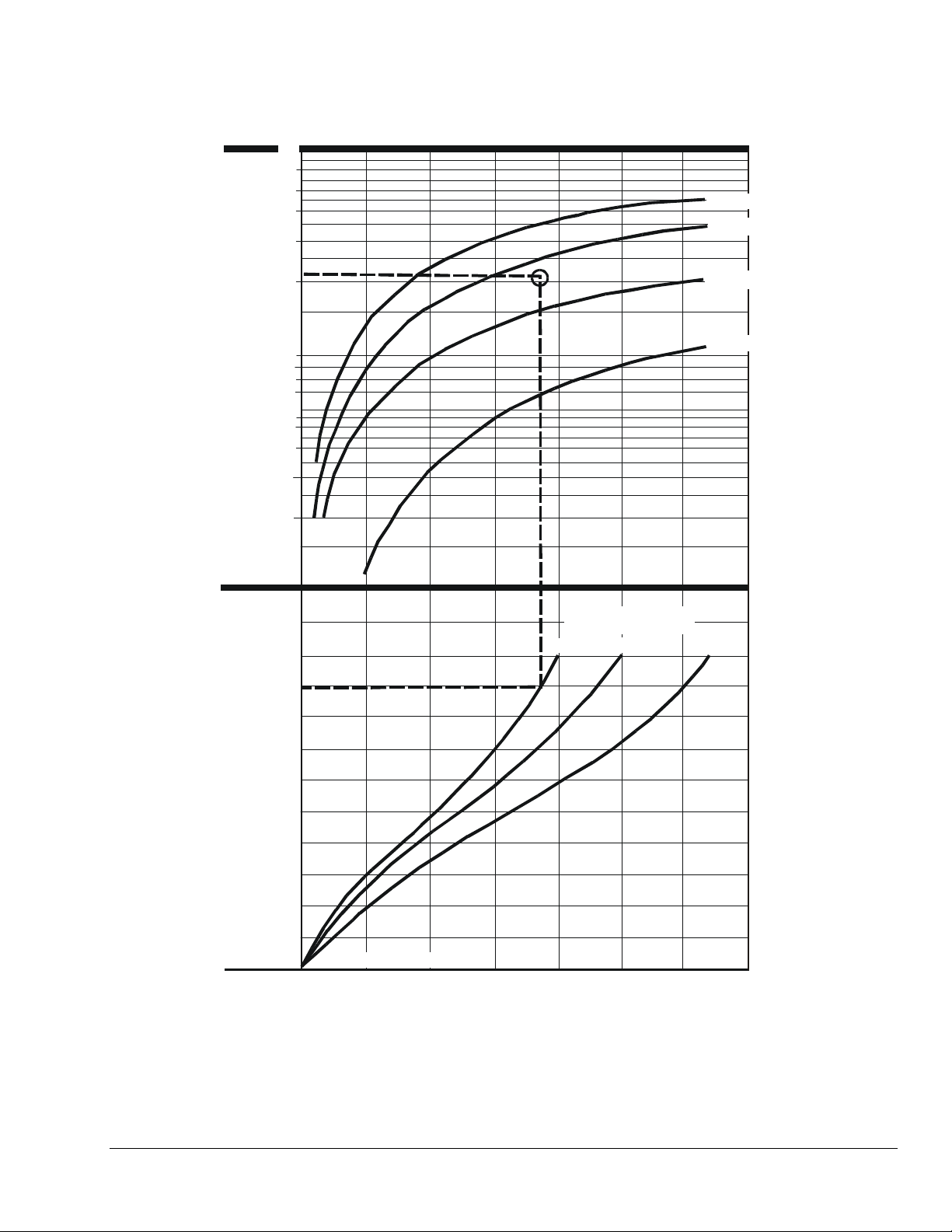
Flowchart
Water Flow
(gpm)
70
50
40
30
10
60
20
5
1-1/4-in. Valve
1-in. Valve
3/4 in. Valve
-
1/2-in. Valve
9
8
7
6
4
3
2
1
Water Pressure Drop
Through Valve (psi)
50
40
30
20
10
Valve Opening Point
0
7
10
15
Figure 5: Water Flow Related to Valve Size and Water Pressure
V48 Series 3-Way Pressure-Actuated Water-Regulating Valves With Union Fittings Installation Instructions 5
Page 6

Technical Data
Product V48 Series Pressure-Actuated Water-Regulating Valves
Body Material
Extension Sleeve, Disc,
Stud, Disc Holder Material
Valve Seat Material Aluminum Bronze
Valve Disc Buna-N
Diaphragm Nylon-Reinforced Buna-N
Water Supply Pressure 150 psig (1034 kPa) Maximum
Water Supply Temperature 170°F (77°C) Maximum
Water Flow See Figure 5.
Sensing Element Brass and Phosphor Bronze Bellows in Brass Cup
Pressure Range See Table 2.
Shipping Weight See Table 3.
The performance specifications are nominal and conform to acceptable industry standards. For application at conditions beyond these
specifications, consult local Johnson Controls/PENN Application Engineering at (800) 275-5676. Johnson Controls, Inc. shall not be liable for
damages resulting from misapplication or misuse of its products.
Refer to the V48 Series 3-Way Pressure-Actuated Water Regulating Valves for Cooling Tower Systems Product Bulletin (LIT-121705) for
necessary information on operating and performance specifications of this product.
1/2-and 3/4-in. Sizes - Cast Brass Bodies,
1-in. and 1-1/4-in. Sizes - Cast Iron Bodies with Rust-Resisting Finish
Brass
Controls Group
507 E. Michigan Street
P.O. Box 423 Printed in U.S.A.
Milwaukee, WI 53201 www.johnsoncontrols.com
6 V48 Series 3-Way Pressure-Actuated Water-Regulating Valves With Union Fittings Installation Instructions
 Loading...