

Page 1
FANs 125, 121
Product/Technical Bulletin V46
Issue Date 1095
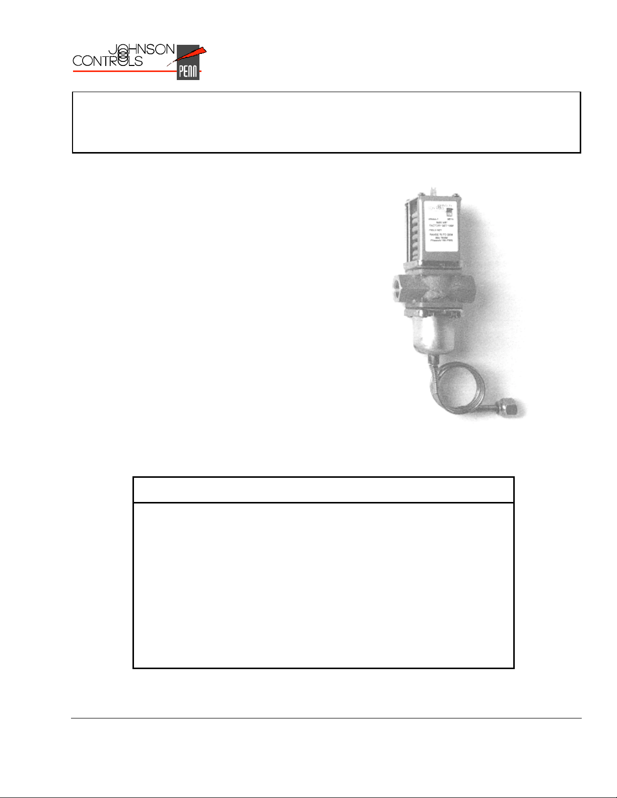
V46 Series Pressure-Actuated Water-Regulating Valves
The V46 pressure-actuated modulating valves come in
two types of control action: direct acting or reverse
acting. Direct-acting V46 valves are typically used for
regulating refrigerant head pressure in water-cooled
condensers. Reverse-acting V46N valves are typically
used for bypass service on refrigeration systems and
heat pump applications. Commercial V46 valves may
be used with standard non-corrosive refrigerants.
V46 models are also available for ammonia refrigerant.
For applications where the coolant may be corrosive to
the valve trim, maritime models are available, which
have nickel copper (monel) valve trim.
❑
No Close Fitting or Sliding
Parts in Water Passages
❑
Corrosion Resistant Material
for Parts that Come in Direct
Contact with Water
❑
Accessible Range Spring Allows easy manual flushing, if required
❑
Take-apart Construction Interior of valves accessible without removing
❑
Pressure-balanced Design Valve maintains consistent setpoint against both
© 1995 Johnson Controls, Inc.
Part No. 24-8414-4, Rev. —
Code No. LIT-125687
Figure 1: V46 Pressure-Actuated
Water-Regulating Valve
Features and Benefits
Provides robust control in less than ideal
conditions
Promotes longer valve life
valve from refrigeration system or pumping down
gradual and sudden water pressure changes
1
Page 2
pplication Overview
A
The V46 direct-acting models open on an increase in
pressure. Models A, B, and C are typically used for
regulating water-cooled condensers, while the low flow
“D” model is generally used in ice machines. The
reverse-acting V46N valve model closes on an
increase in pressure and is typically used for bypass
service on refrigeration systems and heat pumps that
control water temperature.
Commercial V46 valves are available in 3/8 in. through
2-1/2 in. sizes. Commercial all range models
(3/8 through 1-1/2 in.), may be used with standard
non-corrosive refrigerants, or ammonia refrigerant
applications, depending on the model.
V46 series valves also come in models designed for
Navy or maritime salt water applications. These valve
bodies are constructed of bronze, and any metal parts
that come into contact with salt water are constructed
of nickel copper (monel), which withstands the
corrosive action of salt water.
IMPORTANT: All V46 Series water regulating
valves are designed for use only
as operating devices. Where
system closure, improper flow, or
loss of pressure due to valve
failure can result in personal
injury and/or loss of property, a
separate pressure relief or safety
shutoff valve, as applicable, must
be added by the user.
INLET
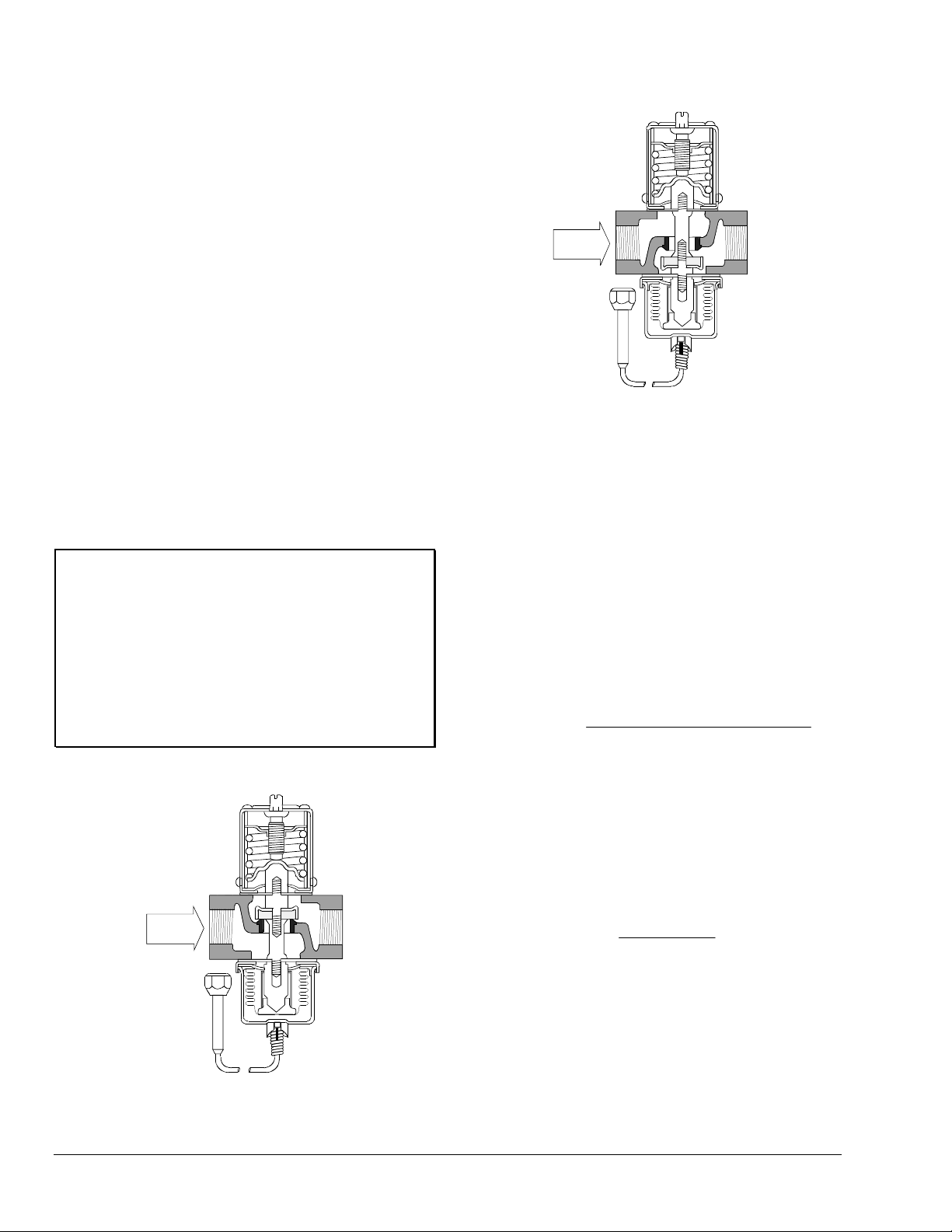
Figure 3: Threaded Type Reverse-Acting
Valve Cross Section
alve Sizing
V
Follow Steps 1 through 3, and use the information
obtained to locate a point on one of the flowcharts
found under
steps.
1. Determine maximum water flow required using
tables provided by the manufacturer of the
condensing unit, or calculate the flow using the
following formula:
Flow(GPM)
V46 Flowcharts
TonsofRefrigerationx15,000
=
500x(Outlet -Inlet Temperature)
that satisfies all three
Note: If the outlet water temperature is unknown,
assume it to be 10°F below the
condensing temperature.
Example: A 9 ton capacity system has an inlet
water temperature of 65°F and an
outlet water temperature of 95°F.
The maximum required water flow is:
INLET
2. Determine refrigerant head pressure rise above
Figure 2: Threaded Type Direct-Acting
Valve Cross Section
2 V46 Series Pressure-Actuated Water-Regulating Valves Product/Technical Bulletin
Flow(GPM)
the valve opening point.
a. Valve closing point (to assure closure under all
conditions) must be the refrigerant pressure
equivalent to the highest ambient air
temperature the equipment will be subjected to
in the off cycle. Read this in psig from a
“Saturated Vapor Table” for the refrigerant
selected.
9x15,000
==
500x(95 - 65)
9GPM
Page 3
b. To determine the valve opening point, add
about 7 psig (48 kPa) to the closing point.
c. From the same table, read the operating head
pressure corresponding to the selected
condensing temperature.
d. Subtract the valve opening point from the
operating head pressure. This gives the head
pressure rise.
3. Determine water pressure drop across the valve.
This is the pressure actually available to force
water through the valve.
a. Determine minimum water pressure available
from city mains or other sources.
b. From condensing unit manufacturer’s tables,
read the pressure drop through condenser
corresponding to the required flow.
c. To the value found in 3b, add the estimated or
calculated drop through installed piping.
d. Subtract the total condenser, piping, and static
head (if applicable) pressure drop from the
available water pressure found in 3a. This is
the available pressure drop across the valve.
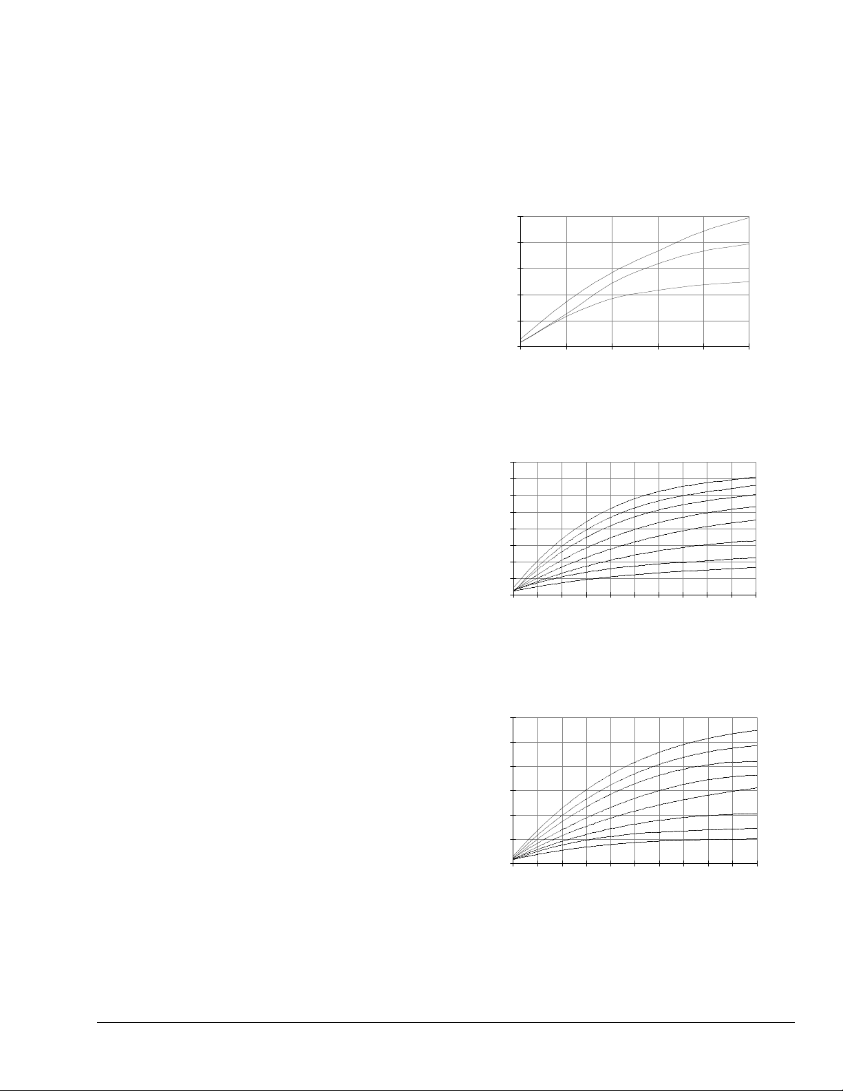
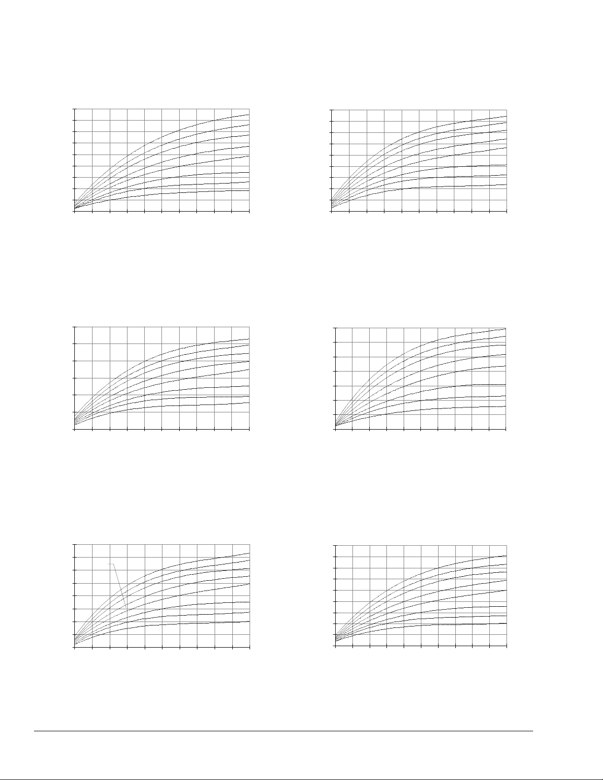
4. Select the proper valve size from the V46
flowcharts by locating a point on a chart that will
satisfy the flow, the head pressure rise above
opening point, and the pressure drop across the
valve.
Example: The required flow for a low-range system is
found to be 27 GPM. Condensing pressure
is 125 psig, and the maximum ambient
temperature is estimated at 86°F. City water
pressure is 40 psig and the manufacturer’s
table gives a pressure drop through the
condenser and the accompanying piping
and valves at 15 psi. Drop through the
installed piping is approximately 4 psi.
Step 1: 27 GPM
Step 2: Closing point is pressure of refrigerant
corresponding to 86°F = 93 psig
Opening point = 93+7 = 100 psig
Operating head pressure = 125 psig
Head pressure rise = 125-100 = 25 psi
Step 3: Minimum pressure = 40 psig
Pressure drop through condenser = 15 psi
Combined pressure drop = 15+4 = 19 psi
Pressure drop across valve = 40-19 = 21 psi
Using a flow of 27 GPM, a head pressure rise of
25 psi, and a pressure drop across the valve of 21 psi,
the only valve that satisfies all three criteria is a
1-1/4 in. valve. See the 1-1/4 in. V46 - All Range chart
on the next page.
V46 Flowcharts
Note: The maximum differential water pressure
across a valve is 60 psi.
2.5
2
1.5
1
Flow ( G PM)
0.5
0
16
14
12
10
8
6
Flow ( G PM)
4
2
0
10 20 30 40 50 60
30
25
20
15
10
Flow ( G PM)
5
0
10 20 30 40 50 60
3/8 in. V46DA - Low Flow
10 20 30 40 50 60
Head Pressure Rise
Abov e Opening Point (psi)
3/8 in. V46 - All Range
Head Pressure Rise
Abov e O p enin g P oint (p si)
1/2 in. V46 - All Range
Head Pressure Rise
Abov e O p enin g P oint ( psi)
60
30
10
Pressure Drop Across Valve (psi)
60
50
40
30
20
10
5
2
Pressure Drop Across Valve (p si)
60
50
40
30
20
10
5
2
Pressure Drop Across Valve (psi)
V46 Series Pressure-Actuated Water-Regulating Valves Product/Technical Bulletin 3
Page 4
45
3/4 in. V46 - All Range
40
35
30
25
20
15
Flow ( G PM)
10
5
0
10 20 30 40 50 60
Head Pressure Rise
Abov e Ope ni n g Point (ps i)
60
50
40
30
20
10
5
2
Pressure Drop Across Valve (psi)
90
80
70
60
50
40
30
Flow ( G PM)
20
10
0
10 20 30 40 50 60
Head Pressure Rise
Abov e Ope ni n g Point (ps i)
60
50
40
30
20
10
5
2
Pressure Drop Across Valve (psi)
1-1/2 in. V46 - All Range
60
50
40
30
20
Flow ( G PM)
10
0
10 20 30 40 50 60
Head Pressure Rise
Abov e Opening Point (psi)
1- 1/4 in. V46 - All Range
80
70
Example
60
50
40
1 in. V46 - All Range
30
Flow ( G PM)
20
10
0
10 20 30 40 50 60
*
Head Pressure Rise
Abov e Ope ni n g Point (ps i)
2 in. V46 - High Range
60
50
40
30
20
10
5
2
Pressure Drop Across Valve (psi)
140
120
100
80
60
Flow ( G PM)
40
20
0
10 20 30 40 50 60
Head Pressure Rise
Abov e O p enin g P oint (p si)
60
50
40
30
20
10
5
2
Pressure Drop Across Valve (psi)
2 in. V46 - Low Range
60
50
40
30
20
10
5
2
Pressure Drop Across Valve (psi)
180
160
140
120
100
80
60
Flow ( G PM)
40
20
0
10 20 30 40 50 60
Head Pressure Rise
Abov e Ope ni n g Point (ps i)
60
50
40
30
20
10
5
2
Pressure Drop Across Valve (psi)
4 V46 Series Pressure-Actuated Water-Regulating Valves Product/Technical Bulletin
Page 5
250
200
150
100
Flow ( G PM)
50
imensions
D
2-1/2 in. V46 - High Range
0
10 20 30 40 50 60
Head Pressure Rise
Abov e Ope ni n g Point (ps i)
250
60
50
40
30
20
10
5
2
Pressure Drop Across Valve (psi)
200
150
100
Flow ( G PM)
50
0
10 20 30 40 50 60
Head Pressure Rise
Abov e O p enin g P oint (p si)
60
50
40
30
20
10
5
2
Pressure Drop Across Valve (psi)
2-1/2 in. V46 - Low Range
(A)
(F)
(C)
(E)
(B)
(D)
(G)
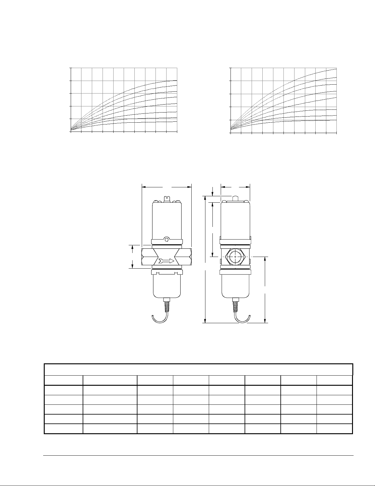
Figure 4: Threaded Type Valves
Table 1: Commercial Service V46 Threaded Connection Dimensions
Dimensions in Inches
Valve Size A B C D E F G
3/8 in. 2-5/8 6-3/4 3-1/8 1-1/2 1-1/4 13/32 3-7/32
1/2 in. 3-1/8 (3-1/4)* 7-13/32 3-3/8 1-27/32 1-1/2 13/32 3-5/8
3/4 in. 3-3/8 (3-5/8)* 7-7/8 3-7/8 2-1/32 1-3/4 13/32 3-21/32
1 in. 4-1/2 (4-7/8)* 10-3/4 5-1/2 2-25/32 2 1/2 4-3/4
1-1/4 in. 4-7/8 11-1/8 5-3/4 2-5/8 2-3/8 1/2 4-29/32
*Note: Values in parenthesis are for maritime valves. All other dimensions remain the same.
V46 Series Pressure-Actuated Water-Regulating Valves Product/Technical Bulletin 5
Page 6
(A)
(E)
(D)
(C)
(B)
(I)
(G)
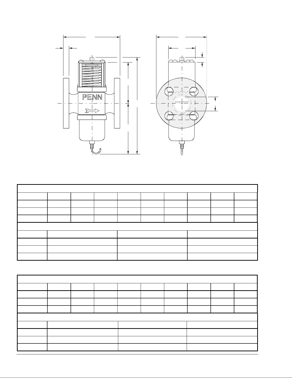
Figure 5: Flange Type Valves
Table 2: Commercial Service: V46 Flange Connection Dimensions
Dimensions in Inches
(H)
(F)
Valve SizeABCDEFGH I
1-1/2 in. 5-5/16 11-1/8 5-3/4 9/16 5 1-7/8 2-5/8 1/2 4-29/32
2 in. 6-5/8 13 6-15/32 5/8 6 2-1/4 3-1/2 1/2 6-1/8
2-1/2 in. 6-3/4 13-1/2 6-3/8 3/4 7 2-23/32 3-1/2 1-1/32 6-3/32
Flange Specifications
Valve Size No. of Holes Hole Size Bolt Circle
1-1/2 in. 4 5/8 3-7/8
2 in. 4 3/4 4-3/4
2-1/2 in. 4 3/4 5-1/2
Table 3: Maritime Service: ASME Flange Connection Dimensions
Dimensions
Valve SizeABCDEFGH I
1-1/2 in. 5-5/16 10-1/2 5-5/8 9/16 5 1-7/8 2-5/8 1/2 5
2 in. 6-3/8 13-1/8 6-1/2 1/2 6 2-3/4 3-1/2 5/8 6
2-1/2 in. 6-3/4 13-1/8 6-1/2 11/16 7 2-3/4 3-1/2 5/8 6
Maritime Service: ASME Flange Specifications
Valve Size No. of Holes Hole Size Bolt Circle
1-1/2 in. 4 5/8 3-7/8
2 in. 4 3/4 4-3/4
2-1/2 in. 4 3/4 5-1/2
6 V46 Series Pressure-Actuated Water-Regulating Valves Product/Technical Bulletin
Page 7
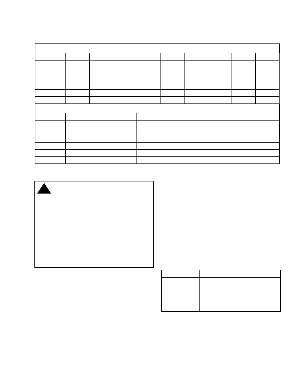
Table 4: Navy “BuShips” Service: Navy Flange Connection Dimensions
Dimensions in Inches
Valve SizeABCDEFGH I
3/4 in. 4-3/16 7-3/4 4 7/16 3-13/16 1-1/8 2-1/32 1/2 3-5/16
1 in 5-5/16 9 4-1/2 1/2 4-1/4 1-1/4 2-5/8 1/2 4
1-1/4 in. 5-5/16 9-11/32 4-11/16 1/2 4-1/2 1-5/8 2-5/8 1/2 4-5/32
1-1/2 in. 5-5/16 10-7/32 5-3/4 1/2 5-1/16 1-7/8 2-5/8 1/2 4
2 in. 6-3/8 14-1/8 6-13/32 1/2 5-9/16 2-3/4 3-1/2 7/16 7-9/32
2-1/2 in. 6-3/8 14-5/16 6-1/2 1/2 6-1/8 2-3/4 3-1/2 5/8 7-3/16
Navy Flange Specifications
Valve Size No. of Holes Hole Size Bolt Circle
3/4 in. 4 9/16 2-11/16
1 in 4 9/16 3-1/8
1-1/4 in. 4 9/16 3-3/8
1-1/2 in. 6 9/16 3-15/16
2 in. 6 9/16 4-7/16
2-1/2 in. 6 9/16 5
ounting
M
!
CAUTION: Equipment Damage Hazard.
To prevent damage to the
capillary, avoid sharp bends or
kinks in the capillary. Coil and
secure excess capillary at the
valve end to avoid tube breakage
due to vibration. Because
harmonic vibration can also break
the tube, some slack must be left
in the capillary. Do not permit the
tubing to rub against metal
surfaces where friction can
damage the capillary.
Flush water lines to clear any foreign matter that may
interfere with valve operation. Mount valves vertically
on the inlet side of the condenser with spring housing
up. If it is necessary to keep the condenser flooded
with coolant, the valve can be mounted on the outlet
side. When mounting the valve in a position other than
vertical, follow the instructions of the equipment in
which the valve will be installed. Make refrigerant head
pressure connection to bellows. If additional capillary
tubing is required, use 1/4 in. O.D. tubing or larger.
djustment
A
Valves may be adjusted with standard service valve
wrenches or screwdrivers, see Table 5. All range
valve settings can be changed quickly from low-range
refrigerants such as R134 to high-range refrigerants
such as R22 or vice versa. To raise the valve opening
point, turn the adjusting screw, located at the top of
range spring housing, counterclockwise. See Figure 8.
Turn the adjusting screw clockwise to lower the
opening point. Exact settings can be made using a
pressure gauge in the refrigerant line to determine the
throttling point. Put the system under normal operating
load and adjust to the desired operating pressure. See
Table 14 for pressure range specifications.
Table 5: Range Adjustment Screw
Valve Size (in.) Range Adjusting Screw
3/8, 1/2, 3/4 1/4 in. square head adjusting screw with
a screwdriver slot
1, 1-1/4, 1-1/2 5/16 in. square head adjusting screw
2, 2-1/2 1/2 in. square head adjusting screw and
a slotted cam
If the compressor operates in high ambient
temperatures, head pressures may remain high
enough during off cycles to prevent the valve from
closing completely. In such instances, the opening
point of the valve should be raised just enough to
cause the valve to close during compressor standby
periods. This will also raise the throttling point.
V46 Series Pressure-Actuated Water-Regulating Valves Product/Technical Bulletin 7
Page 8
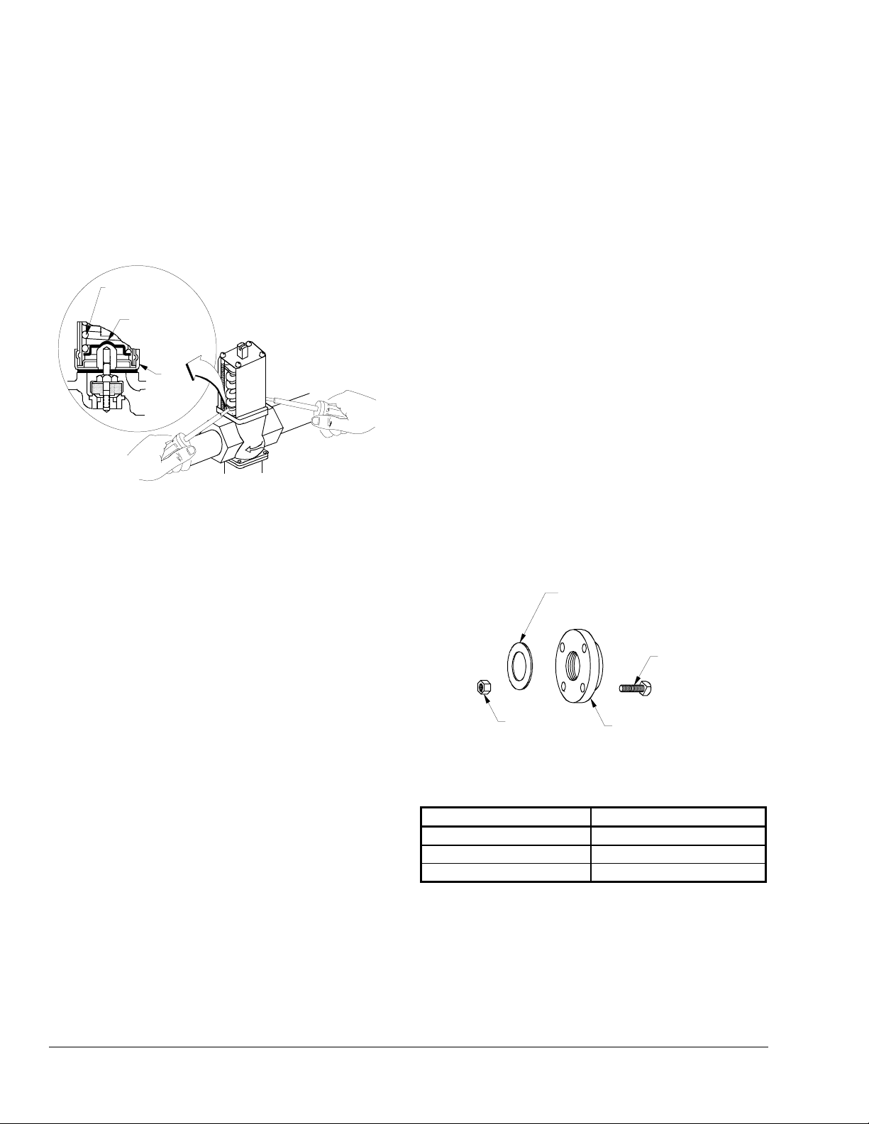
anual Flushing
M
To clear any sediment that might accumulate, valves
may be manually flushed. Insert screwdrivers under
both sides of the valve spring guide and lift upwards to
flush the valve. See Figure 6. Manual flushing does
not affect valve adjustment.
Range
Spring
Valve Spring
Guide
Top
Retainer
Insert screwdrivers
underneath the valve
spring guide.
allowing a single valve to be used for
either low or high range refrigerants.
c. Is a standard open high, or reverse action
close high valve required? See
Table 7: Type
Number Selection Matrix.
d. Is a commercial, maritime, or Navy service
valve needed? Maritime and Navy valves
have bronze bodies and monel internal parts.
3. Companion flange kit by part number, if required.
See section below and
Flange Kits
4. Mounting bracket (3/8 in. and 1/2 in. valve sizes
only) if required, and its position on valve. See
.
Table 8: Pressure Connection Styles
Table 6: Companion
.
Companion Flanges and Gaskets
Figure 6: Manual Flushing
epair Data
R
Replacement of the sensing element, internal parts,
and the rubber diaphragm can be made. For a
replacement valve or replacement parts kit, contact the
nearest Johnson Controls/PENN distributor. For
replacement part kit numbers, refer to Tables 9
through 13. For replacement kit instructions and
details refer to the following bulletins:
and V49 Sensing Element Replacement
V46, V47, V48,
and
V46, V47,
246, and 247 Repair Parts and Service Instructions.
rdering Information
O
When ordering water valves, specify the following:
1. Complete product number.
2. If product number is not known, answer the
following questions and select a valve using
Tables 9 through 13.
Kits are available, at additional cost, for 1-1/2, 2, and
2-1/2 in. flange connection (ASME specifications)
valves only. Each flange kit contains two ring gaskets,
two cast iron flanges, eight machine bolts, and eight
hex nuts.
Ring Gasket for
1-1/2, 2, and
2-1/2 in. Kits (2)
Machine
Bolt (8)
Hex Nut (8)
Figure 7: Flange Kit
Cast Iron
Flange (2)
Table 6: Companion Flange Kits
Kit Number Water Valve Size
KIT 14A-612
KIT 14A-613
KIT 14A-614
1-1/2 in.
2 in.
2-1/2 in.
a. What is the valve size needed? See
section.
Sizing
b. What refrigerant will be used in the system?
See
Table 14: Pressure Range Specifications
Note: 3/8 in. through 1-1/2 in. valves are
supplied with all range construction,
8 V46 Series Pressure-Actuated Water-Regulating Valves Product/Technical Bulletin
Valve
Product Number Selection
For applications that call for valves not listed in
Tables 9 through 13,
.
can be used to specify a custom valve.
Matrix
Example: To order a direct-acting, commercial valve
with a 1-1/4 in. NPT threaded connection,
specify a V46AE.
Table 7: Type Number Selection
Page 9

For more information, contact Application Engineering
at (414) 274-5535.
V46 Series Pressure-Actuated Water-Regulating Valves Product/Technical Bulletin 9
Page 10

Table 7: Type Number Selection Matrix
V46 A Open on Rise, Commercial
B Open on Rise, Maritime
C Open on Rise, Navy
D Open on Rise, Com mercial Low Flow
E Open on Rise, Commercial with
High Pressure Bellows
F Open on Rise, Maritime with
High Pressure Bellows
G Open on Rise, Navy with
High Pressure Bellows
L Open on Rise, Commercial Low Flow
No-Repair
N Open on Fall, Comm ercial
P Open on Fall, Maritime
Q Open on Fall, Commercial Low Flow with
High Pressure Bellows
A 3/8 in. NPT Threaded
B 1/2 in. NPT Threaded
C 3/4 in. NPT Threaded
D 1 in. NPT Threaded
E 1-1/4 in. NPT Threaded
F 1-1/2 in. NPT Threaded
G 9/16–18 Threaded
H 3/8 in. Sweat
J 1/2 in. Sweat
K 3/4 in. Sweat
L 1 in. Sweat
M 1-1/4 in. Sweat
N 3/4 in. Flange
P 1 in. Flange
Q 1-1/4 in. Flange
R 1-1/2 in. Flange
S 2 in. Flange
T 2-1/2 in. Flange
Table 8: Pressure Connection Styles
Commercial Service: Non-corrosive Refrigerant
Valve Style No. Description
45 30 in. (762 mm) copper capillary
with 1/4 in. flare nut and valve
depressor
1-1/2 in. and 5* 1/4 in male flare fitting
Smaller 34* 30 in. (762 mm) copper capillary
with 1/4 in. section for sweat or
flare connection
2 in. and
2-1/2 in.
5 1/4 in. male flare fitting
Commercial Service: Ammonia
1/2 in. to
2-1/2 in.
15 1/4 in. female NPT
Navy and Marine Service
All Sizes 34 30 in. (762 mm) copper capillary
with 1/4 in. section for sweat or
flare connection
*Optional, quantity orders only.
ptions
O
Capillary Tubing Length
Standard length is 30 in. on valves 1-1/2 in. and
smaller. Optional 48 in. (1219 mm) capillary can be
furnished at additional cost, when specified.
Mounting Bracket
A mounting bracket as illustrated in Figure 8, is
available on 3/8 in. and 1/2 in. valves only when
specified. Desired bracket position must also be
specified.
Other styles of brackets on 3/8 in. and 1/2 in. valves
available on quantity orders. For more information,
contact Application Engineering at (414) 274-5535.
10 V46 Series Pressure-Actuated Water-Regulating Valves Product/Technical Bulletin
Page 11
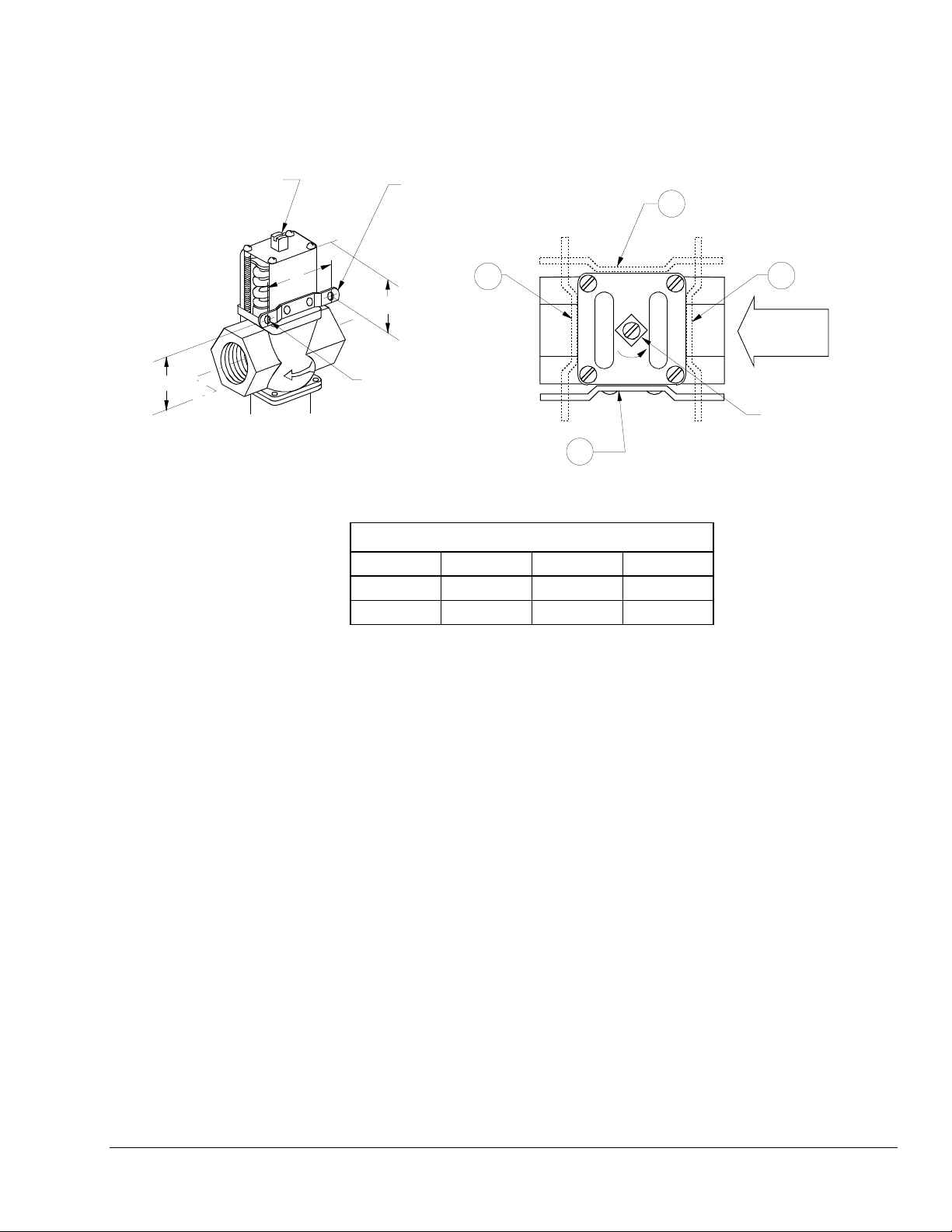
Range Adjusting Screw
(Turn counterclockwise
to raise operation
setpoint.)
Bracket Shown
in Position (1)
2
A
B
4
HIGHER
3
INLET
C
9/32 Diameter
Holes (2)
1
Four mounting bracket
positions (1-4) are av ailable.
Dimensions: in. (mm)
Valve Size A B C
3/8
1/2
2 (51) 1.25 (32) 1.38 (35)
2 (52) 1.85 (47) 1.52 (39)
Figure 8: Mounting Bracket for 3/8 in.
and 1/2 in. Valves
Range Adjusting
Screw
V46 Series Pressure-Actuated Water-Regulating Valves Product/Technical Bulletin 11
Page 12
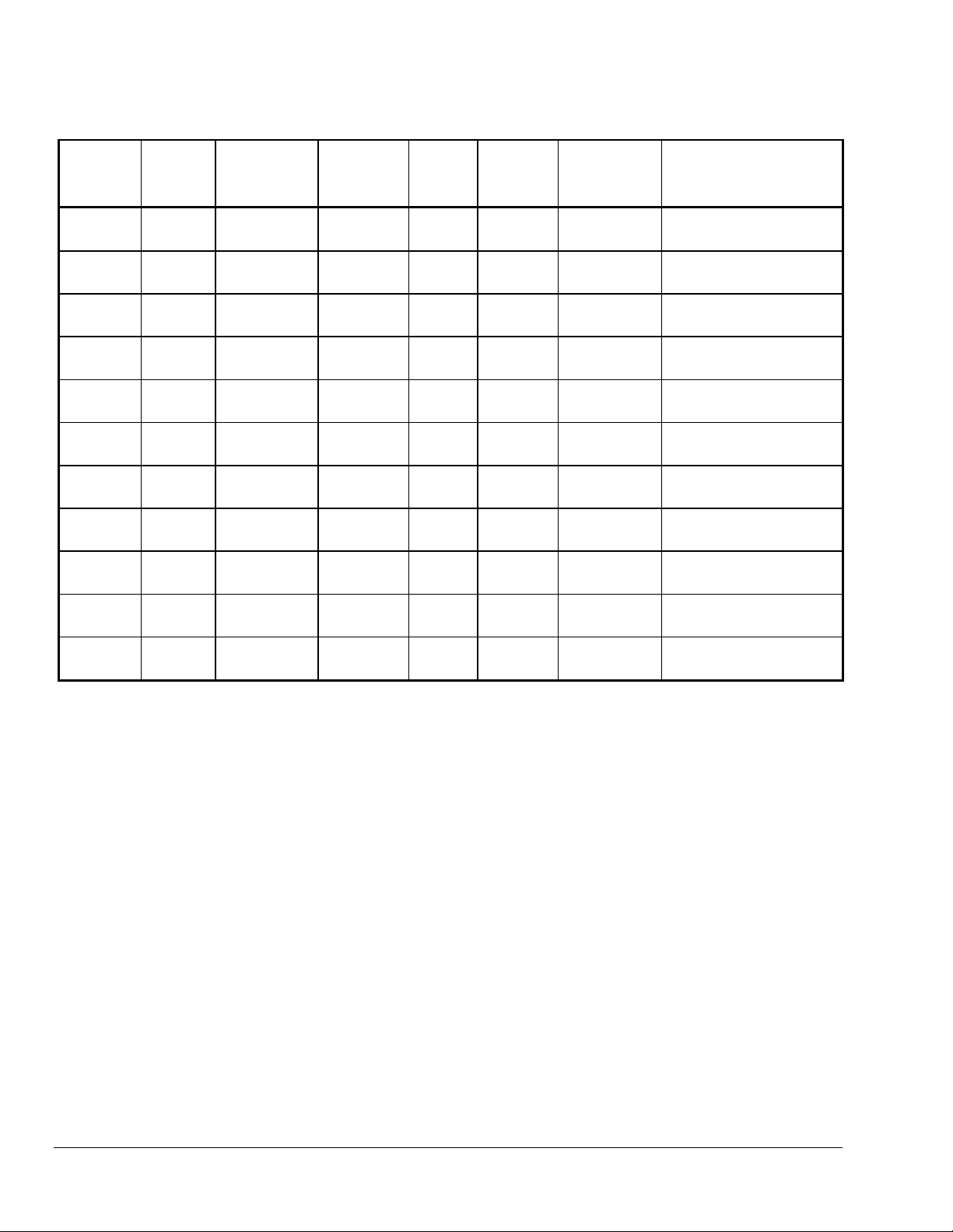
Table 9: Direct-Acting Commercial Type - Non-corrosive Ref rigerants
Product Size (in.) Inlet and
Outlet
V46AA-1 3/8 NPT Threaded All Range 45 2.3 (1.0) STT14A-600R SEP91A-600R and
V46DA-2 3/8 NPT Threaded Extended
V46AB-1 1/2 NPT Threaded All Range 45 3.3 (1.5) STT15A-602R SEP91A-602R and
V46AC-1 3/4 NPT Threaded All Range 45 4.3 (2.0) STT16A-601R SEP91A-601R and
V46AD-1 1 NPT Threaded All Range 45 9.3 (4.0) STT17A-609R SEP91A-603R and
V46AE-1 1-1/4 NPT Threaded All Range 45 10.0 (4.5) STT17A-610R SEP91A-603R and
V46AR-1 1-1/2 NPT 4 Hole
ASME Flange
V46AS-1 2 4 Hole
ASME Flange
V46AS-2 2 4 Hole
ASME Flange
V46AT-1 2-1/2 4 Hole
ASME Flange
V46AT-2 2-1/2 4 Hole
ASME Flange
† Non-stock item, built to order.
* Replacement element supplied with 1/4 in. SAE connector. Order SEC37A capillary kit with flare nuts separately, if needed.
Use only on valves specified.
** Maximum opening point of 70 to 300 psi (483 to 2068 kPa), maximum perm issible refrigerant pressure of 440 psi (3034 kPa).
Service Element
Style
Shipping
Weight
Seat Repair
Kit
Replacement Power
Element
lb (kg)
SEC37A-601R*
45 2.3 (1.0) STT14A-603R SEP91A-600R and
All Range**
All Range 45 13.1 (6.0) STT17A-610R SEP91A-603R and
Low Range 5 25.5 (11.6) STT18A-600R SEP81A-602R†
High Range 5 25.5 (11.6) STT18A-600R SEP81A-601R
Low Range 5 29.5 (11.6) STT18A-601R SEP81A-602R†
High Range 5 29.5 (11.6) STT18A-601R SEP81A-601R
SEC37A-601R*
SEC37A-602R*
SEC37A-602R*
SEC37A-600R*
SEC37A-600R*
SEC37A-600R*
12 V46 Series Pressure-Actuated Water-Regulating Valves Product/Technical Bulletin
Page 13
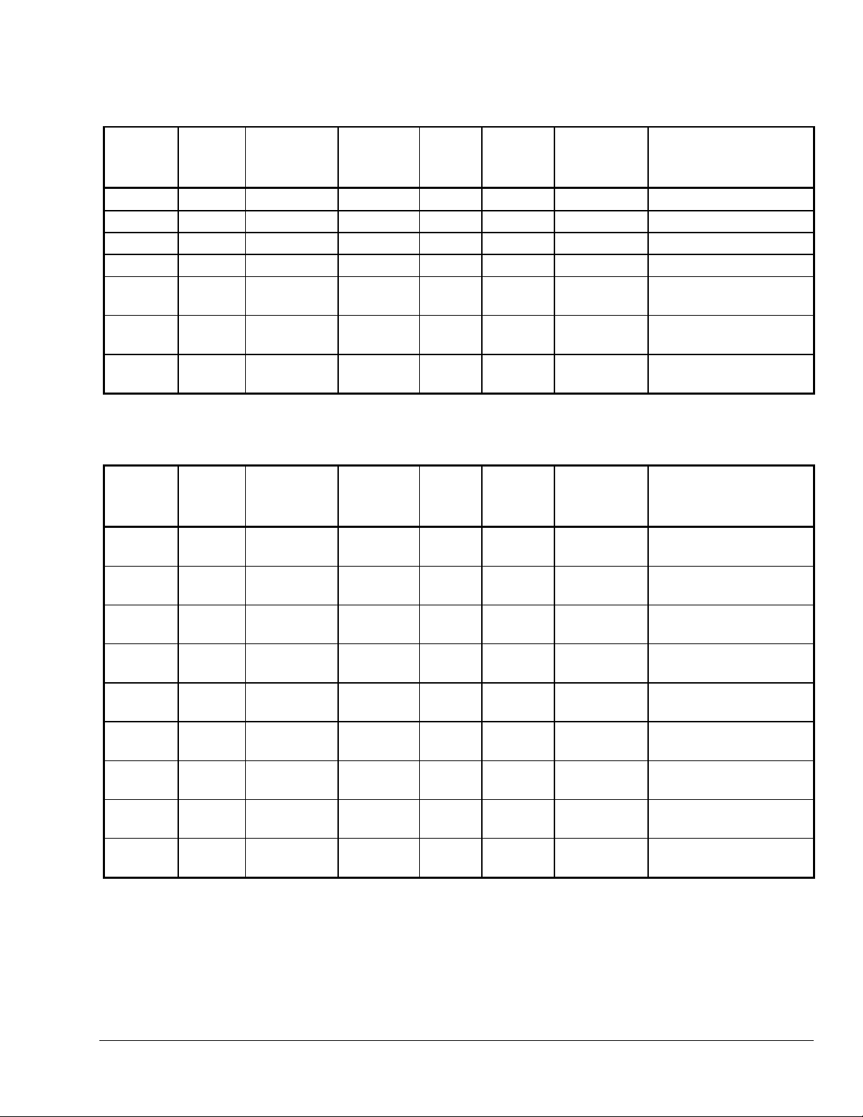
Table 10: Commercial Type - Ammonia
Product Size (in.) Inlet and
Outlet
V46AB-11† 1/2 NPT Threaded Ammonia 15 3.2 (1.5) STT15A-602R SEP70A-603R†
V46AC-8† 3/4 NPT Threaded Ammonia 15 4.2 (1.9) STT16A-601R SEP70A-601R
V46AD-4† 1 NPT Threaded Ammonia 15 7.7 (3.5) STT17A-609R SEP70A-604R
V46AE-4† 1-1/4 NPT Threaded Ammonia 15 9.2 (4.2) STT17A-610R SEP70A-604R
V46AR-2† 1-1/2 4 Hole
ASME Flange
V46AS-3 2 4 Hole
ASME Flange
V46AT-3 2-1/2 4 Hole
ASME Flange
† Non-stock item, built to order.
Service Element
Style
Shipping
Weight
Seat Repair
Kit
Replacement Power
Element
lb (kg)
Ammonia 15 12.3 (5.6) STT17A-610R SEP70A-604R
Ammonia 15 25.5 (11.6) STT18A-600R SEP70A-605R†
Ammonia 15 29.5 (11.6) STT18A-601R SEP70A-605R†
Table 11: Reverse Acting Commercial Type - Non-corrosive Refrigerants
Product Size (in.) Inlet and
Outlet
Service Element
Style
Shipping
Weight
lb (kg)
Seat Repair
Kit
Replacement Power
Element
V46NA-1† 3/8 NPT Threaded All Range 45 2.3 (1.0) STT14A-600R SEP91A-600R and
SEC37A-601R*
V46NB-1† 1/2 NPT Threaded All Range 45 3.6 (1.6) STT15A-602R SEP91A-602R and
SEC37A-602R*
V46NB-2 1/2 NPT Threaded Low Range 45 3.6 (1.6) STT15A-602R SEP91A-602R and
SEC37A-602R*
V46NC-1† 3/4 NPT Threaded All Range 45 4.5 (2.0) STT16A-601R SEP91A-601R and
SEC37A-602R*
V46NC-2 3/4 NPT Threaded Low Range 45 4.5 (2.0) STT16A-601R SEP91A-601R and
SEC37A-602R*
V46ND-1† 1 NPT Threaded All Range 45 7.5 (3.4) STT17A-609R SEP91A-603R and
SEC37A-600R*
V46ND-2 1 NPT Threaded Low Range 45 7.5 (3.4) STT17A-609R SEP91A-603R and
SEC37A-600R*
V46NE-1† 1-1/4 NPT Threaded All Range 45 8.8 (4.0) STT17A-610R SEP91A-603R and
SEC37A-600R*
V46NE-2† 1-1/4 NPT Threaded Low Range 45 8.8 (4.0) STT17A-610R SEP91A-603R and
SEC37A-600R*
† Non-stock item, built to order.
* Maximum bellows pressure is 320 psig (2206 kPa). Replacement element supplied with 1/4 in. SAE connector. Order SEC37A
capillary kit with flare nuts separately, if needed. Use only on valves specified.
V46 Series Pressure-Actuated Water-Regulating Valves Product/Technical Bulletin 13
Page 14
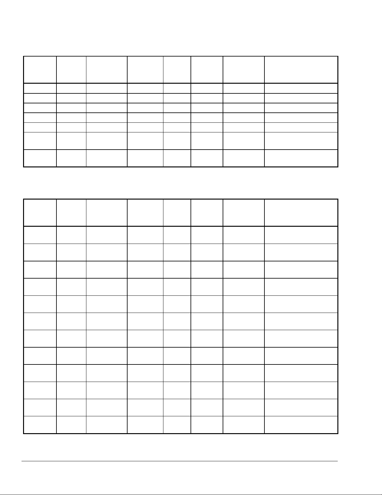
Table 12: Maritime Type - Non-corrosive Refrigerants
Product Size (in.) Inlet and
Outlet
V46BA-2† 3/8 NPT Threaded All Range 34 2.3 (1.0) STT14A-610R SEP13A-602R
V46BB-2† 1/2 NPT Threaded All Range 34 3.3 (1.5) STT15A-603R† SEP13A-600R†
V46BC-2 3/4 NPT Threaded All Range 34 4.3 (2.0) STT17A-613R SEP13A-603R
V46BD-2 1 NPT Threaded All Range 34 9.5 (4.3) STT17A-611R† SEP50A-600R
V46BE-2 1-1/4 NPT Threaded All Range 34 10.3 (4.7) STT17A-612R SEP50A-600R
V46BS-4 2 4 Hole
ASME Flange
V46BT-4† 2-1/2 4 Hole
ASME Flange
† Non-stock item, built to order.
Service Element
Style
Shipping
Weight
Seat Repair
Kit
Replacement Power
Element
lb (kg)
High Range 34 25.5 (11.6) STT18A-602R SEP50A-601R†
High Range 34 29.5 (13.4) STT18A-602R SEP50A-601R†
Table 13: Navy Type - Non-corrosive Refrigerants
Product Size (in.) Inlet and
Outlet
Service Element
Style
Shipping
Weight
lb (kg)
Seat Repair
Kit
Replacement Power
Element
V46CJ-2† 1/2 Sweat
Connector
V46CN-2† 3/4 4 Hole
Navy Flange
V46CP-2† 1 4 Hole
Navy Flange
V46CQ-2† 1-1/4 4 Hole
Navy Flange
V46BR-2† 1-1/2 4 Hole
ASME Flange
V46CR-2† 1-1/2 4 Hole
Navy Flange
V46BS-3† 2 4 Hole
ASME Flange
V46CS-3† 2 4 Hole
Navy Flange
V46CS-4† 2 4 Hole
Navy Flange
V46BT-3† 2-1/2 4 Hole
ASME Flange
V46CT-3† 2-1/2 4 Hole
Navy Flange
V46CT-4† 2-1/2 4 Hole
Navy Flange
† Non-stock item, built to order.
All Range 34 3.6 (1.6) STT15A-603R† SEP13A-600R†
All Range 34 7.1 (3.2) STT17A-613R SEP13A-603R
All Range 34 12.0 (5.4) STT17A-611R† SEP50A-600R
All Range 34 10.3 (4.7) STT17A-612R SEP50A-600R
All Range 34 13.5 (6.1) STT17A-612R SEP50A-600R
All Range 34 13.8 (6.3) STT17A-612R SEP50A-600R
Low Range 34 25.5 (11.6) STT18A-602R SEP50A-601R†
Low Range 34 24.4 (11.1) STT18A-602R SEP50A-601R†
Low Range 34 24.4 (11.1) STT18A-602R SEP50A-601R†
Low Range 34 29.5 (13.4) STT18A-602R SEP50A-601R†
Low Range 34 25.5 (11.6) STT18A-602R SEP50A-601R†
High Range 34 25.5 (11.6) STT18A-602R SEP50A-601R†
14 V46 Series Pressure-Actuated Water-Regulating Valves Product/Technical Bulletin
Page 15
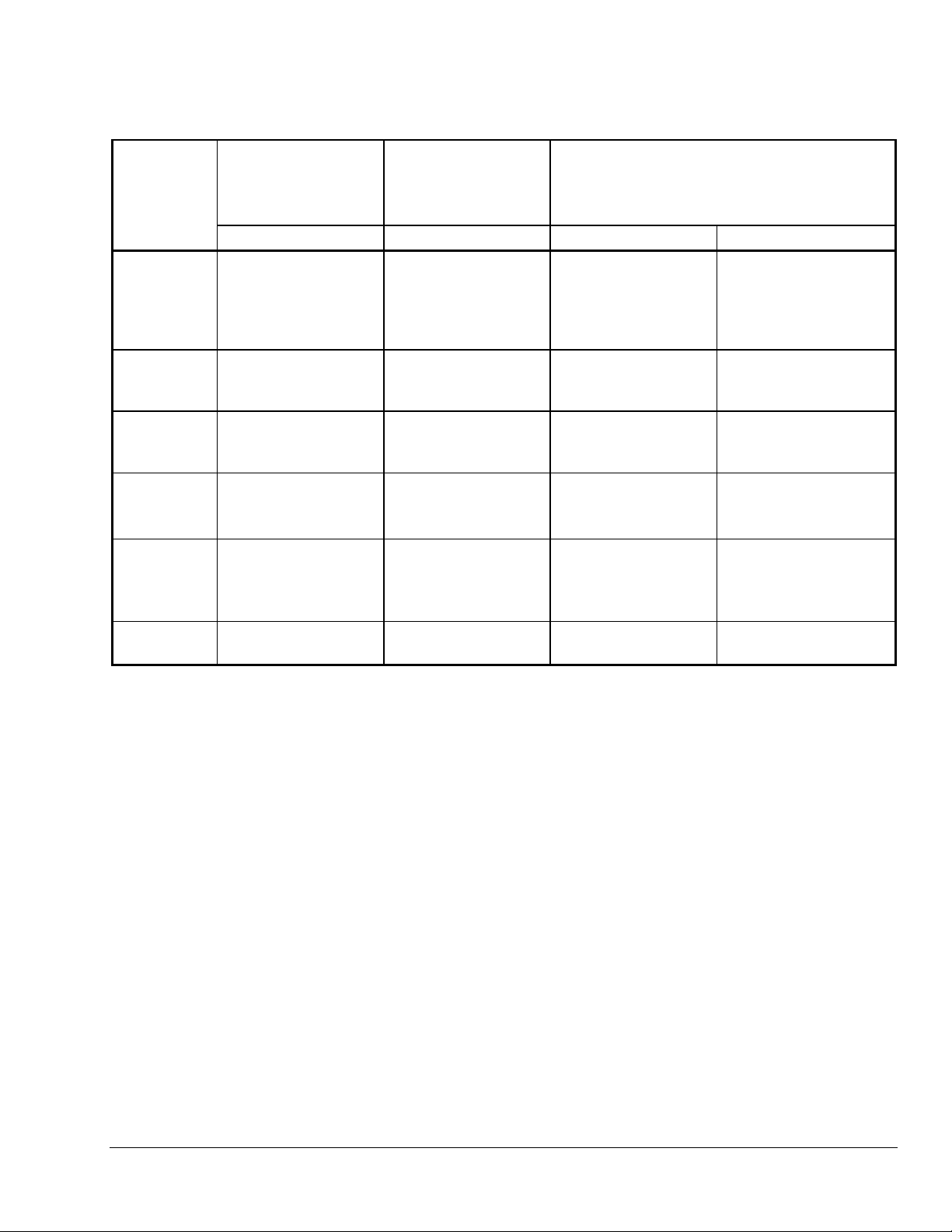
Table 14: Pressure Range Specifications
Refrigerant Maximum Opening
Point psig (kPa)*
Modulation Start
Point
psig (kPa)*
V46A, B, C, D V46N Water Refrigerant
All Range
R12, R22,
R134a,
R502, R404a,
R507
All Range
with High
Overpressure
3/8 in.
Extended
All Range
2 and 2-1/2 in.
Low Range
R12, R134a
2 and 2-1/2 in.
High Range
R22, R502,
R404a, R507
Ammonia
R717
* V46A, B, C direct acting valve ranges indicate the valve opening point,
V46N reverse acting valve ranges indicates the modulation start point.
** For heat pump applications (3/8 in. through 1-1/2 in. sizes only).
70 to 260
(483 to 1793)
70 to 260
(483 to 1793)
70 to 300
(483 to 2068)
70 to 170
(483 to 1172)
160 to 260
(1103 to 1793)
100 to 200
(690 to 1379)
90 to 280 (621 to 1931)
40 to 100 (276 to 690)**
___________
___________
100 to 200
(690 to 1379)
180 to 280
(1241 to 1931)
130 to 230
(896 to 1586)
Maximum Permissible Pressure psig (kPa)
150 (1034) 320 (2206)
150 (1034) 370 (2551)
150 (1034) 440 (3034)
150 (1034) 230 (1586)
150 (1034) 320 (2206)
150 (1034) 320 (2206)
V46 Series Pressure-Actuated Water-Regulating Valves Product/Technical Bulletin 15
Page 16

Notes
16 V46 Series Pressure-Actuated Water-Regulating Valves Product/Technical Bulletin
Page 17

pecifications
S
Product
Body Material
Extension Sleeve, Disc,
Stud, Disc Holder Material
Valve Seat Material
Valve Disc
Diaphragm
Water Supply Pressure
Water Supply Temperature
Sensing Element
Pressure Range
Shipping Weight
The performance specifications are nominal and conform to acceptable industry standards. For application at conditions beyond these specifications,
consult the local Johnson Controls office. Johnson Controls, Inc. shall not be liable for damages resulting from misapplication or misuse of its products.
V46 Series Pressure Actuated Valve
Commercial:
Navy and Maritime
Commercial:
Navy and Maritime:
Commercial:
Navy and Maritime:
Buna-N
Nylon Reinforced Buna-N
150 psig (1034 kPa) Maximum
170
F (77°C) Maximum
°
Non-corrosive Refrigerants:
Navy and Maritime:
2 and 2-1/2 in.
High Range Service:
Ammonia Service:
See
Table 14: Pressure Range Specifications.
See Tables 9-13.
3/8, 1/2, or 3/4 in. Sizes Have Cast Brass Bodies, Other Commercial
Types Have Cast Iron Bodies with Rust Resisting Finish
: Cast N aval Bronze
Brass; Monel is Available at Additional Cost
Monel
Aluminum Bronze; Monel is Available at Additional Cost
Monel
Brass and Phosphor Bronze Bellows in Brass Cup
Monel Bellows in Brass Cup
Monel Bellows in Brass Cup
Stainless Steel Bellows in Brass Cup
Controls Group
507 E. Michigan Street
P.O. Box 423
Milwaukee, WI 53201 Printed in U.S.A.
V46 Series Pressure-Actuated Water-Regulating Valves Product/Technical Bulletin 17
 Loading...