

Page 1
TABULAR DATA SHEET
Outdoor Split System Air Conditioner 2 Thru 5 Tons
MODELS: TCGF24* THRU 60
14.5 SEER – R-410A, 1 PHASE
Physical and Electrical Data
MODEL TCGF24S41S1 TCGF30S41S1 TCGF36S41S1 TCGF42S41S1 TCGF48S41S1 TCGF60S41S1
Unit Supply Voltage 208-230V, 1φ, 60Hz
Normal Voltage Range
Minimum Circuit Ampacity 16.8 18.4 19.1 23.9 27.9 35.9
Max. Overcurrent Device Amps
Min. Overcurrent Device Amps
Compressor Type Scroll Scroll Scroll Scroll Scroll Scroll
Compressor
Amps
Crankcase Heater No No No No No No
Fan Motor Amps Rated Load .8 .8 1.5 1.5 1.5 1.5
Fan Diameter Inches 22 22 22 24 24 24
Fan Motor
Coil
Liquid Line Set OD (Field Installed) 3/8 3/8 3/8 3/8 3/8 3/8
Vapor Line Set OD (Field Installed) 3/4 3/4 3/4 7/8 7/8 1 1/8
Unit Charge (Lbs. - Oz.)
Charge Per Foot, Oz. 0.62 0.62 0.62 0.67 0.67 0.75
Operating Weight Lbs. 128 130 145 172 180 199
1.Rated in accordance with ARI Standard 110, utilization range “A”.
2.Dual element fuses or HACR circuit breaker. Maximum allowable overcurrent protection.
3.Dual element fuses or HACR circuit breaker. Minimum recommended overcurrent protection.
4.The Unit Charge is correct for the outdoor unit, matched indoor coil and 15 feet of refrigerant tubing. For tubing lengths other than
15 feet, add or subtract the amount of refrigerant, using the difference in length multiplied by the per foot value.
1
2
3
Rated Load 12.8 14.1 14.1 17.9 21.1 27.5
Locked Rotor 58 73 77 112 115 135
Rated HP 1/8 1/8 1/4 1/4 1/4 1/4
Nominal RPM 1075 1075 850 850 850 850
Nominal CFM 2750 2800 3200 3600 3600 3700
Face Area Sq. Ft. 13.1 17.4 17.4 20.0 21.4 24.0
Rows Deep 1 1 1 1 1 1
Fin / Inches 23 23 23 23 23 23
4
25 30 30 40 45 60
20 20 20 25 30 40
3 - 2 3 - 7 3 - 10 4 - 4 4 - 9 5 - 9
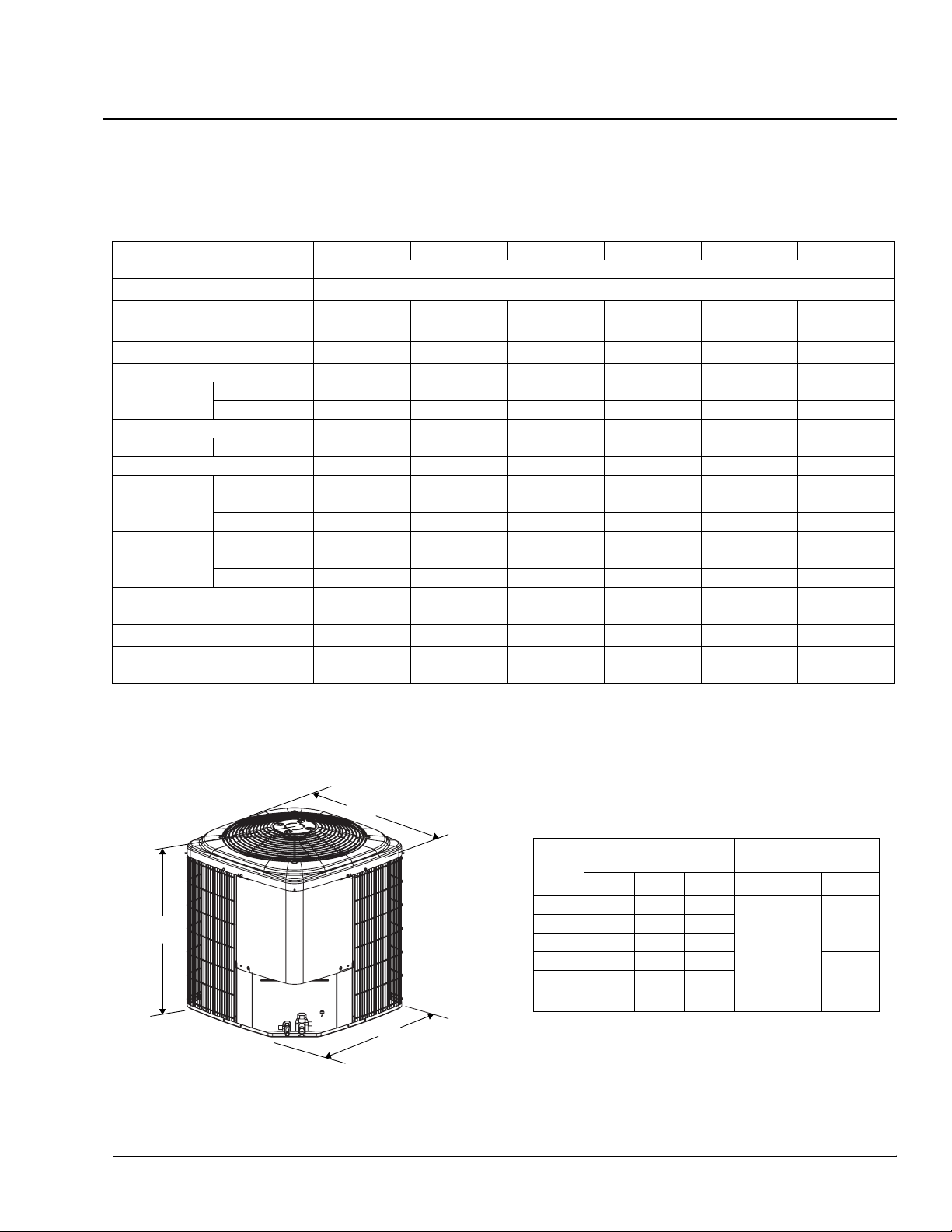
All dimensions are in inches. They are subject to change
without notice. Certified dimensions will be provided upon
C
request.
187 to 252
Unit
Model
24 28 29 29
A
B
36 36 29 29
42 34 33.6 33.6
48 36 33.6 33.6
60 40 33.6 33.6
1. Including Fan Guard.
2. Adapter fitting required for 1-1/8” line set.
Dimensions
(Inches)
1
A
B C Liquid Vapor
Refrigerant Connection
Service Valve Size
3/4”30 36 29 29
3/8”
7/8”
2
7/8”
Johnson Controls Unitary Products 362564-UTD-B-0708
Page 2
362564-UTD-B-0708
R-410A SYSTEM CHARGING PROCEDURE
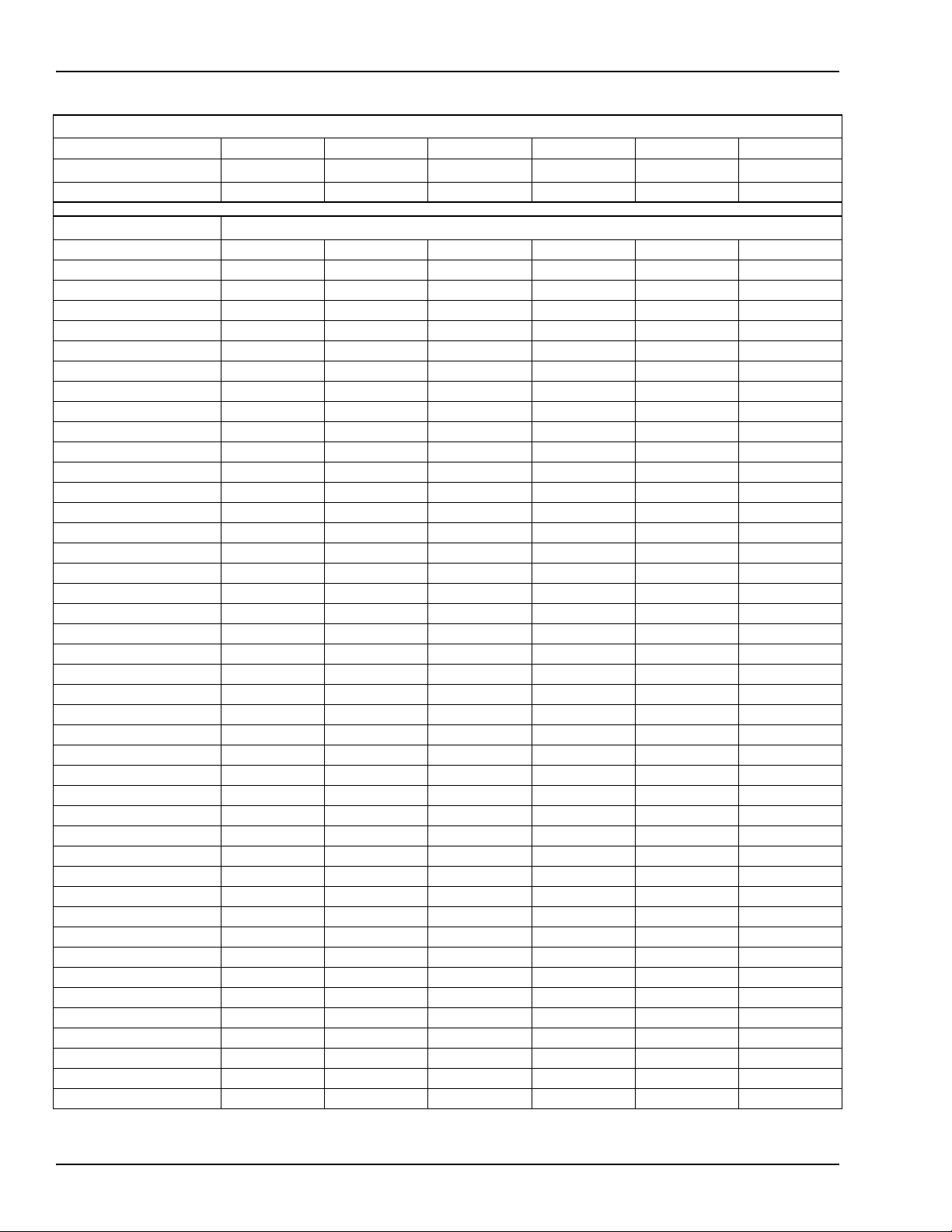
Additional R-410A Charge / Orifice Size for Various Matched Systems
Outdoor Unit TCGF24S41S1 TCGF30S41S1 TCGF36S41S1 TCGF42S41S1 TCGF48S41S1 TCGF60S41S1
Required Orifice or TXV
Factory Charge, lbs-oz 3 - 2 3 - 7 3 - 10 4 - 4 4 - 9 5 - 9
1
1TVM902 1TVM903 1TVM903 1TVM903 1TVM905 1TVM906
Indoor Coil
FC/MC/PC24A3X 5 – – – – –
FC/MC/PC24B3X 5 – – – – –
FC/MC/PC30A3X 12 2 – – – –
FC/MC/PC30B3X 12 2 – – – –
FC/MC/PC32A3X 16 10 – – – –
FC/MC/PC35B3X 16 10 – – – –
FC/MC/PC35C3X 16 10 – – – –
FC/MC/PC36A3X 8 4 – – – –
FC/MC/PC36B3X 8 4 8 – – –
FC/MC/PC36C3X 8 4 1 – – –
FC/MC/PC37A3X 24 19 15 – – –
FC/MC/PC43B3X 24 19 15 5 – –
FC/MC/PC43C3X 24 19 15 5 – –
FC/MC/PC48C3X 40 32 15 17 16 –
FC/MC/PC48D3X 40 32 27 17 16 –
FC/MC/PC60D3X – – – 17 16 0
FC/MC62D3X – – – 25 26 18
UC24A3X 8 – – – – –
UC24B3X 8 – – – – –
UC30A3X 8 4 – – – –
UC30B3X 8 4 – – – –
UC36A3X – – – – – –
UC36B3X – – – – – –
UC36C3X – – – – – –
UC42B3X – – – – – –
UC42C3X – – – – – –
UC48C3X – – – – – –
UC48D3X – – – – – –
UC60C3X – – 12 – – –
UC60D3X – – 12 – – –
HC18A3X – – – – – –
HC30A3X 10 – – – – –
HC36B3X 16 11 8 – – –
HC42C3X 25 19 15 6 – –
HC60D3X – – – 0 0 0
HD24*3X 16 – – – – –
HD36*3X 18 – – – – –
HD48*3X 51 42 36 24 25 –
HD60*3X – – – – 24 –
AHP18B3X – – – – – –
AHP24B3X 3 – – – – –
AHP30B3X 16 – – – –
AHP36C3X – 19 15 – – –
2,3,4
Additional Charge, Oz
2 Johnson Controls Unitary Products
Page 3

362564-UTD-B-0708
R-410A SYSTEM CHARGING PROCEDURE
Additional R-410A Charge / Orifice Size for Various Matched Systems (Continued)
Outdoor Unit TCGF24S41S1 TCGF30S41S1 TCGF36S41S1 TCGF42S41S1 TCGF48S41S1 TCGF60S41S1
Required Orifice or TXV
1
Factory Charge, lbs-oz 3 - 2 3 - 7 3 - 10 4 - 4 4 - 9 5 - 9
1TVM902 1TVM903 1TVM903 1TVM903 1TVM905 1TVM906
Indoor Coil
2,3,4
Additional Charge, Oz
AHP42C3X – – – – – –
AHP/SHP60D3X – – – – 1 –
AV24B3X 3 – – – – –
AV36C3X 25 19 15 – – –
AV/SV48D3X – – 9 0 1 –
AV/SV60D3X – – – 0 1 0
F4FP024
F4FP030
F4FP036
F4FP040
F4FP042
F4FP045
F5FP048
F5FP060
F4FV060
See Caution below
See Caution below
See Caution below
See Caution below
See Caution below
See Caution below
See Caution below
See Caution below
See Caution below
0 – – – – –
3 0 – – – –
– 8 5 – – –
– 12 8 – – –
– – 8 0 – –
– – 9 2 – –
– – 20 10 11 –
– – 20 10 11 –
– – 9 10 1 –
FOOTNOTES:
1. Systems matched with furnace or air handlers not equipped with blower-off delays may require blower Time Delay Kit 2FD06700224.
2. PC coils cannot be used in downflow or horizontal applications. FC coils cannot be used in horizontal applications.
3. A TXV kit must be used with these coils to obtain system performance. Note: If a TXV is factory installed on the coil, it must be replaced
with the listed TXV
4. Refer to Technical Guide for actual system performance and matches.
PROCEDURES:
1. Unit factory charge listed on the unit nameplate includes refrigerant for the condenser, the smallest evaporator and 15 feet of interconnecting line tubing.
2. Verify the TXV or orifice and additional charge required for specific evaporator coil in the system using the above table.
3. Add additional charge for the amount of interconnecting line tubing greater than 15 feet at the rate specified in Physical and Electrical Data Table.
4. For TXV match charge weight needs to be weighed in for specififc coil match and lineset length.
5. Permanently mark the unit nameplate with the total system charge. Total System Charge = Base Charge (as shipped) + adder for
evaporator + adder for line set.
If the F*FP Air Handler used has a with a factory installed R-22 TXV it MUST BE CHANGED OUT to a R-410A TXV or a orifice for proper operation.
If the TXV is not changed out system damage will occur.
Johnson Controls Unitary Products 3
Page 4

NOTES
Subject to change without notice. Printed in U.S.A. 362564-UTD-B-0708
Copyright © 2008 by Johnson Controls, Inc. All rights reserved. Supersedes: 362564-UTD-A-0608
Johnson Controls Unitary Products
5005 York Drive
Norman, OK 73069
*362564*
 Loading...