

Page 1
High Resolution
Touch Screen
model T9580
Residential
Digital Thermostat
with Humidity Control
Code No. LIT-12012451
Issued October 3, 2017
Owner’s Manual
and Installation
Instructions
Page 2
CAUTION
IMPORTANT
Follow the Installation Instructions before proceeding.
Set the thermostat mode to “OFF” prior to changing
settings in setup or restoring factory defaults.
North American Emissions Compliance
United States Canada
Compliance Statement (Part 15.19)
This device complies with Part 15 of the FCC
Rules. Operation is subject to the following
two conditions:
1. This device may not cause harmful
interference, and
2. This device must accept any interference
received, including interference that may
cause undesired operation.
Warning (Part 15.21)
Changes or modifications not expressly
approved by the party responsible for
compliance could void the user’s authority
to operate the equipment.
This color touch screen has the ability to receive updates to its firmware.
Periodically firmware updates are released by the manufacturer to add features
and/or performance enhancements. This manual was produced reflecting the
most current firmware/feature set at the time of publication, firmware rev. 5.10.
Firmware releases after rev. 5.10 may not be adequately depicted in this manual.
Please refer to the appropriate website or contact your place of purchase to learn
about changes to the thermostat after firmware release 5.10.
Industry Canada Staement
The term IC before the certification/
registration number only signifies
that the Industry Canada technical
specifications were met.
Le terme “IC” précédant le numéro
d’accréditation/inscription signifie
simplement que le produit est
conforme aux spécifications
techniques d’Industry Canada.
T9100
T9580
i
Page 3

Glossary of Terms
Auto-Changeover: A mode in which the thermostat will turn on the
heating or cooling based on room temperature demand.
Cool Setpoint: The warmest temperature that the space should rise
to before cooling is turned on (without regard to deadband).
Deadband: The number of degrees the thermostat will wait, once a
setpoint has been reached, before energizing heating or cooling.
Differential: The forced temperature difference between the heat
setpoint and the cool setpoint in Auto Mode.
Heat Setpoint: The coolest temperature that the space should drop
to before heating is turned on (without regard to deadband).
Icon: The word or symbol that appears on the thermostat display.
Mode: The current operating condition of the thermostat
(i.e. Off, Heat, Cool, Auto).
Non-Programmable Thermostat: A thermostat that does not have
the capability of running Time Period Programming.
Programmable Thermostat: A thermostat that has the capability of
running Time Period Programming.
Temperature Swing: Same as Deadband.
Time Period Programming: A program that allows the thermostat
to automatically adjust the heat setpoint and/or the cool setpoint
based on the time of the day. Same as Schedule.
ii
Page 4

Table of Contents
GET TO KNOW YOUR THERMOSTAT
Home Screen .......................................................................................1
Menu Screens ......................................................................................1
Dropdown Dashboard .........................................................................2
Care and Use of Your Thermostat .....................................................5
QUICK START
Selecting Your Desired Temperature and Mode ..............................6
Using the Fan Button .........................................................................6
Setting the Time & Date ....................................................................7
Setting the Time ...........................................................................8
Setting the Date ...........................................................................9
Daylight Savings Setup.................................................................9
Connecting to Wi-Fi ................................................................... 10
WiFi Set up - Create a Skyport Account ................................. 12
MAIN MENU BUTTONS
SCHEDULE ......................................................................................... 13
View My Schedule...................................................................... 14
Edit My Schedule ....................................................................... 14
SMART FAN ....................................................................................... 16
Smart Fan On/Off ...................................................................... 17
Smart Fan Minimum Runtime .................................................. 17
Start/Stop Times ........................................................................ 17
Days to allow Smart Fan operation ......................................... 17
SCREENSAVER .................................................................................. 18
Screensaver On/Off .................................................................... 19
ScreensaverSetup ....................................................................... 19
Screensaver Preview ................................................................... 19
iii
4
Page 5

Table of Contents
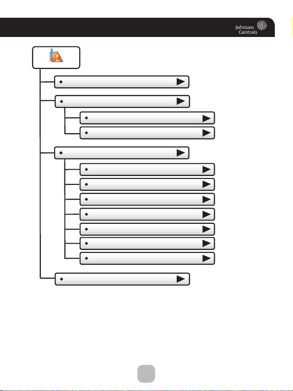
ALERTS ............................................................................................ 20
View Current Alerts .................................................................21
Reset Alerts ..............................................................................21
Set/Edit Reminders ..................................................................21
Service Information (Who To Call For Service) ....................21
DISPLAY .......................................................................................... 22
Active Brightness .................................................................... 23
Idle Brightness ........................................................................ 23
Night Dimmer ......................................................................... 23
Maintenance ........................................................................... 24
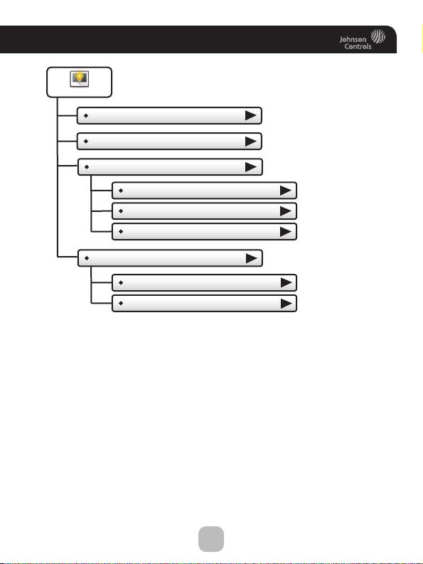
PREFERENCES ................................................................................ 25
User Interface Themes ........................................................... 26
Custom Wallpaper .................................................................. 26
Heat/Cool Indicator ................................................................ 26
Sound Options ........................................................................ 26
VACATION/AWAY........................................................................... 27
Clear Vacation Schedule ........................................................ 28
Set Vacation Schedule ........................................................... 29
Modes & Setpoints ................................................................. 29
SECURITY ........................................................................................ 30
Auto Screenlock ......................................................................31
Setpoint Limits ........................................................................31
INFORMATION ............................................................................... 32
View Runtime Graphs ............................................................. 33
Who to Call for Service ......................................................... 33
SETTINGS ........................................................................................ 34
Thermostat Name ................................................................... 38
Available Modes ..................................................................... 38
SD Card (Import and Export) ................................................ 38
iv
Page 6

Table of Contents
GENERAL SETUP .............................................................................38
Units (F or C) ..............................................................................38
Language .....................................................................................39
Smart Recovery On/Off .............................................................39
Simple Thermostat On/Off ........................................................39
AUTOMATED DEMAND RESPONSE ...............................................40
INSTALLATION SETTINGS...............................................................54
Heat & Cool Stages ....................................................................54
Heat & Cool Stages ...............................................................54
Compressor Stages ................................................................54
Aux Heat Stages ....................................................................54
Timers & Deadbands...................................................................54
Free Cooling ................................................................................56
Heat Pump Settings ....................................................................57
Heat Pump Lockout - Enabled/Disabled ..............................57
Heat Pump Lockout Outdoor Temp ......................................57
Aux Heat Lockout Enabled/Disabled ....................................57
Aux Heat Lockout Temp ........................................................57
Dual Fuel Settings .................................................................57
Dual Fuel On/Off .............................................................57
Changeover With Outdoor Temp On/Off ......................57
Adjust Balance Point.......................................................57
AUX Output Settings .................................................................58
Fan Off Delay .............................................................................59
Sensor Settings ...........................................................................59
Control Sensor .......................................................................59
Wireless Sensor .....................................................................59
Wired Sensor .........................................................................59
Calibrate Sensors Use ...........................................................60
Test Outputs ...............................................................................60
Dealer Information ..................................................................... 61
v
Page 7

Table of Contents
Upgrade Firmware ...........................................................................61
Delete Custom Images .....................................................................61
Reset to Factory Default Settings..................................................61
Restart Thermostat ..........................................................................61
WI-FI ................................................................................................62
Wi-Fi Enabled ..............................................................................63
Status ............................................................................................63
Setup .............................................................................................63
Local API .......................................................................................63
SKYPORT ...........................................................................................67
Account ........................................................................................67
EMERGENCY HEAT ..........................................................................68
COLORDISPLAY DESKTOP APP ....................................................69
Installing the ColorDisplay Desktop App .....................................69
Uploading Photos ............................................................................70
INSTALLATION INSTRUCTIONS ...................................................71
Remove & Replace the Old Thermostat ......................................... 71
Wire Connections ............................................................................72
Determining Your Existing Wiring and Equipment ......................73
Making 4 Wires Work When 5 Wires Are Required ....................75
Making 5 Wires Work When 6 Wires Are Required ....................76
The T9580 Thermostat Backplate ..................................................77
Explanation Of the Thermostat Dip Switches ..............................78
Sample Wiring Diagrams.................................................................79
TROUBLESHOOTING ........................................................................82
INDEX .....................................................................................83
WARRANTY ...........................................................................87
TECHNICAL SPECIFICATIONS...............................................88
vi
Page 8
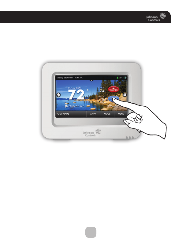
Get To Know Your Thermostat
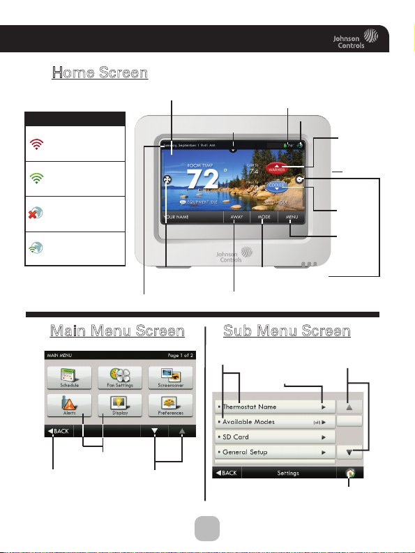
Home Screen
Backlit Color Touch Screen Display
Connectivity Symbol Table
Not connected
to Wi-Fi
Connected to local
access point w/IP
address without
Skyport enabled
Connected to local
access point w/IP
address, but not yet
connected to Skyport
Connected to Skyport
Main Menu Screen
Menu
Back
Button
Buttons
Fan Button
Date & Time
Scrolling
Buttons
Outdoor Te mperature
(If optional accessory is used
or connected to Skyport)
Drop Down
Sensor Button
Home/Away Button
Connectivity Symbol
Mode Buttons
Sub Menu Screen
Sub Menu
Buttons
Indicates Options
Available
Warmer
Button
SD Card
Slot
Cooler
Button
Menu
Button
Scrolling
Buttons
Home Button
1
Page 9
Get To Know Your Thermostat
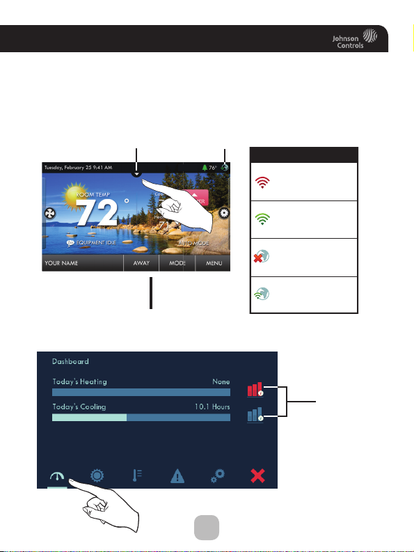
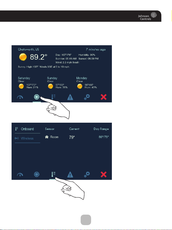
Dropdown Dashboard
The Dropdown Dashboard displays temperature and other readings.
It will also show the high and low readings of the day.
Drop Down
Dashboard Button
Wi-Fi
Connection
Icon
Connectivity Symbol Table
Not connected
to Wi-Fi
Connected to local
access point w/IP
address without
Skyport enabled
Connected to local
access point w/IP
address, but not yet
connected to Skyport
Connected to Skyport
(The contents of your Dashboard may vary)
Dropdown Dashboard
2
Heating and
Cooling amounts
for the day
press for
more info
Page 10
Get To Know Your Thermostat
(The contents of your Dashboard may vary)
Dropdown Dashboard
Weather
Display
Thermostats
Onboard
Weather
Display with
forecast for the
following 3 days
This page displays
sensor information.
Select ‘Onboard’
to view room
temperature
sensors that are
built-into the
thermostat. Select
‘Wireless’ to view
all wireless sensors
that this thermostat
has access to.
3
Page 11
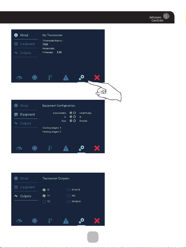
Get To Know Your Thermostat
These 3 screens are for
informational purposes
only. Settings may not
be changed from these
screens.
Thermostat
Info
Equipment
Configuration
Thermostat
Outputs
4
Page 12
Get To Know Your Thermostat
Care and Use of Your Thermostat
Pencils, pens and other sharp objects should never be used on your
thermostat; these may damage your touchscreen. Only use your
finger tip to press the touchscreen buttons.
Use a soft, damp cloth to clean the screen.
CAUTION
DO NOT USE ABRASIVE CLEANERS OR CLEANERS THAT CONTAIN
SOLVENTS. DO NOT SPRAY ANYTHING DIRECTLY ONTO THE
THERMOSTAT.
ATTENTION
NE PAS UTILISER UN NETTOYANT ABRASIF OU UN NETTOYANT QUI
CONTIENT DES SOLVANTS. NE PAS VAPORISER DIRECTEMENT SUR LE
THERMOSTAT.
5
Page 13
Quick Start -
Temperature, Modes & Fan
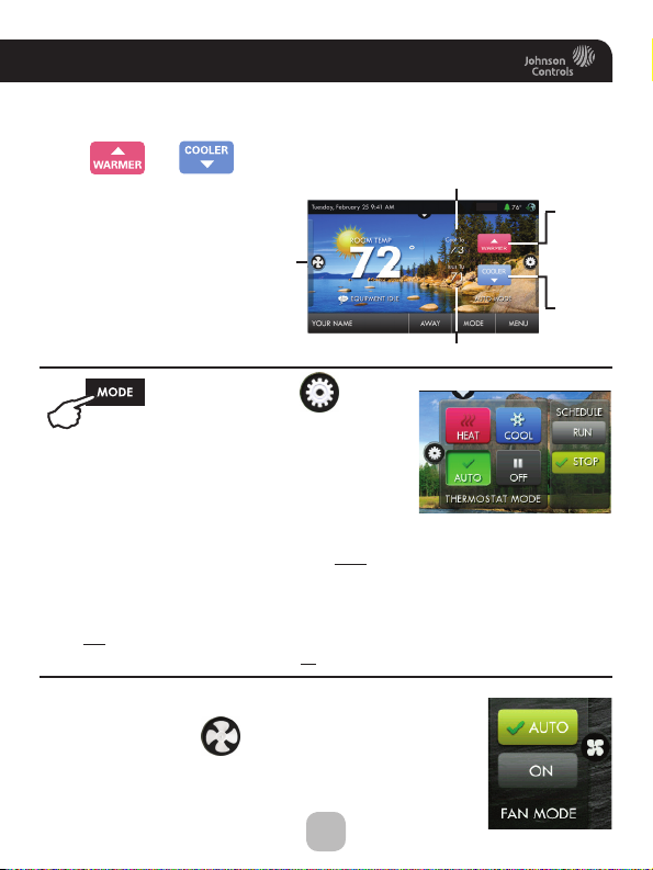
Selecting Your Desired Temperature and Mode
Press or to adjust temperature
The Heat or Cool Setpoint
is the temperature the
room has to reach before
heating or cooling will
turn off.
Press
HEAT will allow only heat operation.
COOL will allow only cool operation.
AUTO will allow both Heat and Cool operation.
OFF - heating and cooling systems are turned off.
AUTO-CHANGEOVER MODE - Pressing the WARMER or
COOLER buttons in Auto mode will adjust both the heat and cool setpoints
simultaneously. To adjust heat and cool setpoints individually, choose HEAT mode
to adjust the heat setpoint and COOL mode to adjust the cool setpoint, then return
to AUTO mode.
HEAT OR COOL MODE - Pressing the WARMER or COOLER buttons in Heat or
Cool mode will adjust only the heat or cool setpoints.
or the MODE Icon
Fan
Cool Setpoint
Heat Setpoint
Warmer
Button
Cooler
Button
Using the Fan Button
Press the FAN Icon
FAN ON fan runs constantly even in OFF Mode.
FAN AUTO fan only runs with a heating or cooling demand.
6
Page 14
Quick Start -
NOTE: When the thermostat is connected to a Sk yport account,
the Time & Date are automatically synchronized to the Skyport
Set Time & Date
Set Current Time
Use AM/PM - ON
Set Current Date
Daylight Savings Setup
Cloud, including automatic Daylight Savings adjustments.
Your time zone is selected in the Skyport web application.
Daylight Savings Time - OFF
Start Schedule
Stop Schedule
Set Time & Date
Starts On
Day
Month
Ends On
Day
Month
(2nd)
(Sun)
(March)
(1st)
(Sun)
(November)
7
Page 15
Quick Start -
Setting the Time
Set Time & Date
Press
Press
MENU
then
Set Time & Date
Set Current Time
Press
Press
Choose
For 12 hour AM/PM clock
For 24 hour clock
Press
hr +
and
hr -
BACK
when finished.
Use AM/PM - ON
Use AM/PM - OFF
BACK
when finished.
to scroll down.
min +
to set the current time.
min -
(12:00 AM)
Press
8
Page 16
Quick Start -
Press
Setting the Date
Set Current Date
Press
Daylight Savings Setup
Tu rn Daylight Savings
Time on or off.
Adjust when Daylight
Savings Time begins.
Adjust when Daylight
Savings Time ends.
Press
after making a change
to a selection.
Press
or the Home button
when finished.
or
Press the day on the calendar
Su Mo Tu We Th Fr Sa
27 28 29 30 1 23
45678910
1211
18
19 20 21 22 23 24
1234567
BACK
BACK
Set Time & Date
6/1/2013
to set the current month and year.
13
Daylight Savings Time - OFF
Daylight Savings Time - ON
Start Schedule
Stop Schedule
17161514
31302928272625
Starts On
Day
Month
Ends On
Day
Month
9
Press
when finished.
(2nd)
(Sun)
(March)
(November)
(1st)
(Sun)
BACK
Page 17
Quick Start - Connect to Wi-Fi
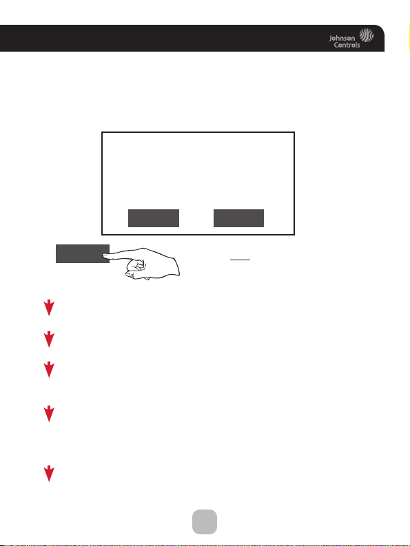
Connect to Wi-Fi (from initial start up)
When power is connected to the thermostat and it has not been
configured to connect to a Wi-Fi Access point, the following
message appears:
Wi-Fi Set Up
No Wi-Fi access points are
configured for your thermostat.
Would you like to set up one now?
YES NO
YES
Select the access point you wish to connect to from the list.
Enter the password for the Wi-Fi Access Point and press NEXT.
Select automatic setup and press NEXT.
When finished, a dialog box will appear confirming the successful
connection to the local Wi-Fi Access Point.
Select OK, then the Wi-Fi status page will appear. Upon closing
of the Wi-Fi status page, you will be asked to join the thermostat
to a Skyport account.
Select YES and follow the onscreen instructions to create a new
Skyport account or to add the thermostat to an existing account.
Press YES
10
Page 18
Quick Start -
72
MENU
72
Press Wi-Fi
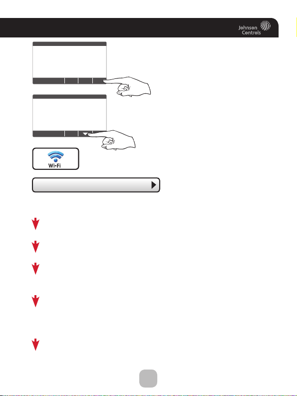
Connect to Wi-Fi (from menus)
Press MENU
Press DOWN
• Wi Fi Setup
Select the access point from the list that you want to
connect to.
Enter the password for the Wi-Fi Access Point and press NEXT.
Select automatic setup and press NEXT.
When finished, a dialog box will appear confirming the successful
connection to the local Wi-Fi Access Point.
Select OK, then the Wi-Fi status page will appear. Upon closing
of the Wi-Fi status page, you will be asked to join the thermostat
to a Skyport account.
Select YES and follow the onscreen instructions to create a new
Skyport account or to add the thermostat to an existing account.
Press Wi-Fi Setup
11
Page 19
Quick Start - Connect to Wi-Fi (from menus)
Although there is more than one way to create a Skyport account, the
steps below illustrate creation from a browser.
If the thermostat is connected to the local Wi-Fi Access Point, but not
yet joined to a Skyport account, you may join the thermostat to an
account by doing the following:
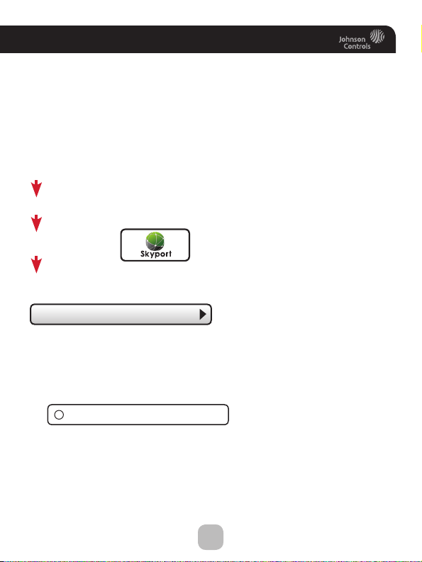
Select MENU from the thermostat’s home screen.
Scroll down
Select Skyport
Select Skyport Account and follow the onscreen instructions.
• Skyport Account
1. Open your browser to: https://JCI.skyportcloud.com
2. Select “Create account now”
4
Create Account Now
3. Follow on screen instructions to create an account and add a
thermostat to the Skyport account.
12
Page 20
Main Menu Buttons -
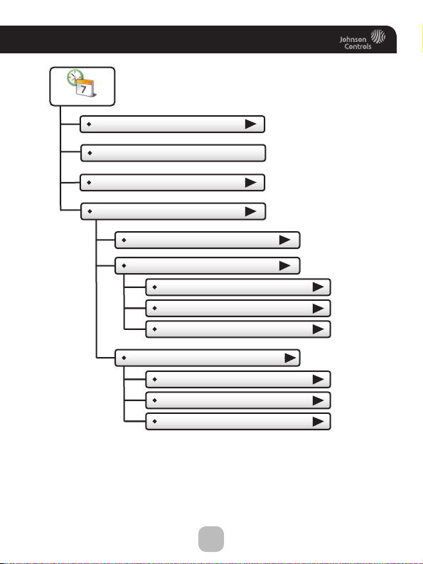
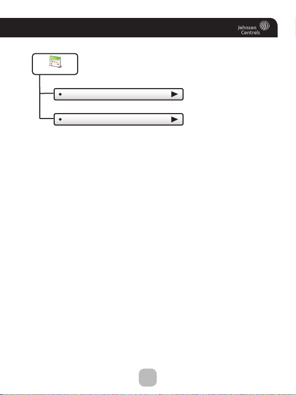
Schedule
View My Schedule
Edit My Schedule
Schedule
13
Page 21
Main Menu Buttons -
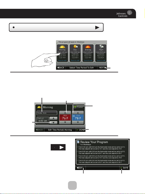
This thermostat features up to four programmable
time periods per 24 hour day: Morning, Day, Evening,
and Night. The start time for each time period is
Schedule
adjustable. The stop time for each time period is
the start time for the next period.
Schedule
View My Schedule
Press a day of the week to view its settings. This may be repeated for each day.
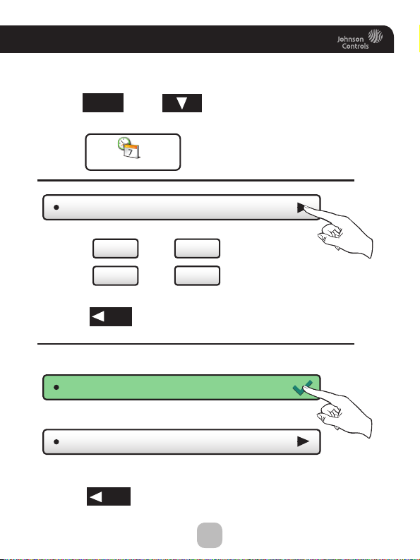
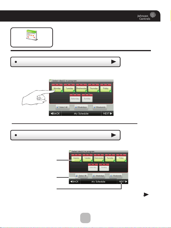
Edit My Schedule
Press and select days to program
Select individual days
Select groups of days
Then press NEXT
or
Continued
14
Page 22
Main Menu Buttons -
Schedule
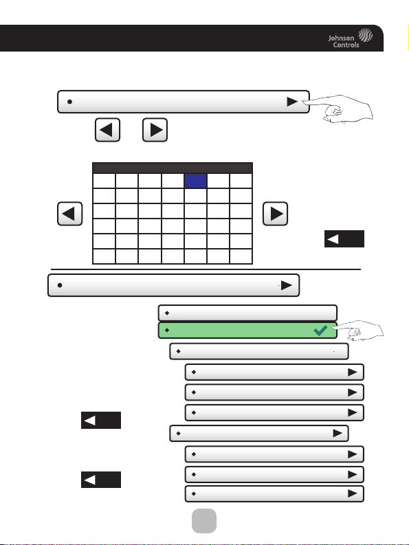
Edit My Schedule
Press and select a Time Period (Morning, Day, Evening, or Night) to edit.
Adjust Mode, Start Time, and Heat and Cool Setpoints to desired settings.
The Time Period may also be Enabled or Disabled. Un-check the Enabled
box for Time Periods you don’t want to use. Press DONE when finished.
Mode
Start Time
When you are finished editing the
four time periods press
Review your program.
Press SAVE to keep your program.
Press EDIT to make further changes.
Heat and Cool Setpoints
NEXT
Edit
15
Done
(Continued)
Next
Enable/Disable
Time Period
Save
Page 23
Main Menu Buttons -
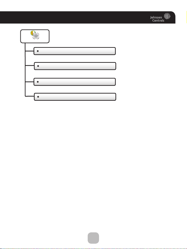
Smart Fan
Who To Call For Service
Smart Fan - OFF
View Runtime Graphs
Smart Fan Min Runtime
Who To Call For Service
Start/Stop Times
View Runtime Graphs
Days To Run Fan
Smart Fan
16
Page 24
Main Menu Buttons -
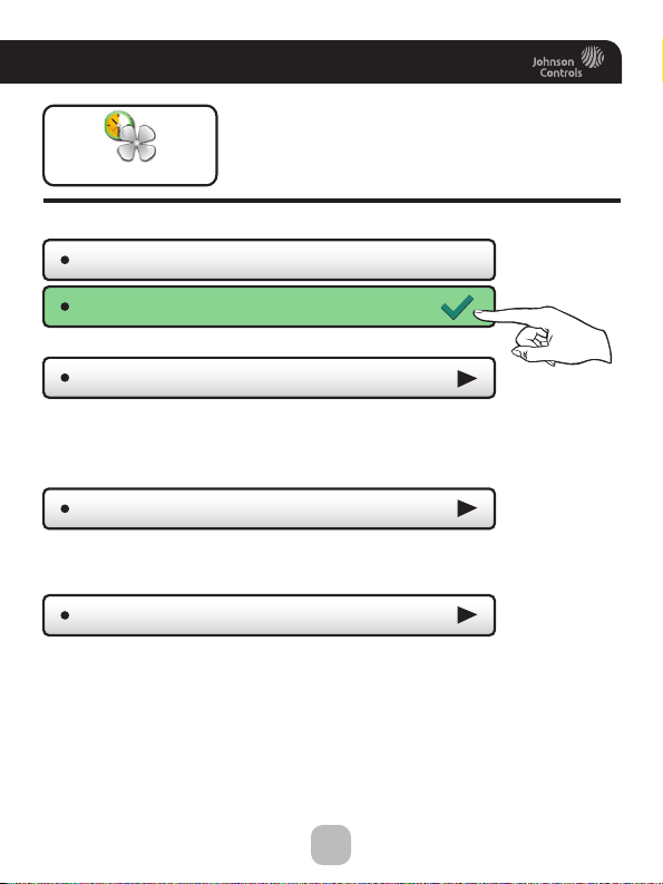
The fan may be programmed to
turn on automatically for a specified
Smart Fan
Press to turn fan schedule on or off
Smart Fan - OFF
Smart Fan - ON
period during the day.
Smart Fan
Smart Fan Min Runtime
Set the minimum number of minutes the fan will run from the top
of each hour. Set runtime to 60 minutes to be on continuously
from Start Time to Stop time. (5 - 60 mins.)
Start/Stop Times
Set when the Smart Fan schedule will start and stop. For example,
you may not want Smart Fan to run during sleeping hours.
Days To Run Fan
Choose which days of the week Smart Fan will run.
(7:00AM - 9:00PM)
(10m)
17
Page 25

Main Menu Buttons -
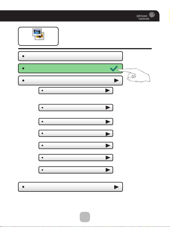
Screensaver
Who To Call For Service
Screensaver - OFF
View Runtime Graphs
Screensaver Setup
Screensaver Turn On Delay
Screensaver Type
Slideshow
Digital Clock
Analog Clock
Change Image After...
Use Theme Images - OFF
Randomize Slideshow - OFF
Show Clock - OFF
Home Screen Info - OFF
View Runtime GraphsScreensaver Preview
Screensaver
18
Page 26
Main Menu Buttons -
Screensaver
The Screensaver allows you
to create custom slideshows.
Screensaver
Screensaver - OFF
Screensaver - ON
Screensaver Setup
Screensaver Turn On Delay
How long after a button press for the
Screensaver to appear. 1, 3, 5, or 30 minutes
Screensaver Type
Slideshow, Digital Clock, Analog Clock
Change Image After...
15, 30 seconds -
Use Theme Images - OFF
Slideshow uses included Theme Images. Off or On
Randomize Slideshow - OFF
Shuffles slideshow photos in random order
Show Clock - OFF
Shows the time and date every 5 photos. Off or On
Home Screen Info - OFF
Shows the mode, setpoints, and temperature after
every 10 photos. Off or On.
Screensaver Preview
1, 5, or 10 minutes
Press this button to preview your screensaver operation
before returning to the Home Screen.
After the preview, press anywhere on the screen to
return to the sub menu.
(5m)
(Slideshow)
19
Page 27
Main Menu Buttons -
Alerts
View Current Alerts
Reset Alerts
Reset Air Filter Alert
Reset UV Lamp Alert
Set/Edit Reminders
Service Call - OFF
Days Until Service Call
Air Filter Reminder - OFF
Set Max Filter Runtime
Set Max Filter Days
UV Lamp Reminder - OFF
Max UV Lamp Runtime
Service Information...
Alerts
(0 days)
(300 hrs)
(0 days)
(360 days)
20
Page 28

Main Menu Buttons -
The alerts let you know when
Alerts
your system needs service.
Alerts
View Current Alerts
View and reset current
service alerts here.
Alerts will appear
on the bottom bar
of the Home Screen.
Press to view and
reset current alerts.
Reset Alerts
Clear and reset current service alerts.
Set/Edit Reminders
Set service alert runtimes and turn reminders on or off.
Service Call Reminder - OFF
Days Until Service Call
Air Filter Reminder - OFF
Set Max Filter Runtime
Set Max Filter Days
UV Lamp Reminder - OFF
Set Max UV Lamp Runtime
(0 days)
(500 hrs)
(300 days)
(300 days)
Dealer’s
Logo
here
Service Information...
View your service company’s contact information.
21
Page 29
Main Menu Buttons -
Display
Active Brightness
Idle Brightness
Night Dimmer
Auto Night Dimmer - OFF
Set Idle Brightness
Set Dimmer Schedule
Maintenance
Screen Cleaning
To uch Calibration
Display
22
Page 30

Main Menu Buttons -
The display brightness options
may be adjusted in this menu.
Display
Display
Active Brightness
You may select how bright the backlight is while the thermostat is active.
The display is active for 3 minutes after last touch, it then goes Idle.
Idle Brightness
You may select how bright the backlight is while the thermostat is idle.
(80%)
(30%)
Night Dimmer
You may dim the brightness of the screen at night.
Auto Night Dimmer - OFF
The screen can be set to dim automatically at night.
Dimming the display can prolong the life of the backlight.
Set Idle Brightness
Set the screen brightness for the Night Dimmer. When Night Dimmer
is On, the display will go idle 8 seconds after last touch.
Set Dimmer Schedule
Set the schedule for the Night Dimmer.
(20%)
23
Page 31

Main Menu Buttons -
Display
Maintenance
Maintenance allows you to clean and calibrate the
touch screen.
Screen Cleaning
Screen Cleaning Mode disables the touch feature
for 15 seconds so the screen may be cleaned without
altering any settings.
Use a soft cloth without solvents or abrasive cleaners
To uch Calibration
Under normal circumstances, the touchscreen should
not need to be calibrated.
Touch and hold the center of the targets as they appear
on the screen for 3 seconds.
Touch Scre en Calibration
Press when done.
FINISH
When calibration is complete, the thermostat will automatically
restart and return to the Home Screen.
24
Page 32

Main Menu Buttons -
Preferences
User Interface Themes
Custom Wallpaper
Heat/Cool Indicator
Heat/Cool Indicator OFF
Taskbar red/white OFF
Room Temp red/blue OFF
Mode Status red/blue OFF
Sound Options
Beep - OFF
Beep Sound
Preferences
25
Page 33

Main Menu Buttons -
You may set the type of back ground
that appears on the thermostat
Preferences
Home Screen.
Preferences
User Interface Themes
This thermostat has several high quality background themes to choose from.
NOTE: At 7pm, the back ground will change to an evening scene.
At 7am it will return to a daytime scene.
(ocean)
Custom Wallpaper
You may choose your own background image by selecting a
photo that you have uploaded from an SD memory card.
Heat/Cool Indicator
You may choose an enhanced indicator of the current status
of the HVAC equipment.
Heat/Cool Indicator - ON/OFF
Taskbar Red/White - ON/OFF
Room Te mp Red/Blue - ON/OFF
Mode Status Red/Blue - ON/OFF
Sound Options
Beep - ON
Beep - OFF
Turn the beep sound on or off.
Beep Sound
(Beep 1)
Choose from different beep sounds.
26
Page 34

Main Menu Buttons -
Va cation/Away
Clear Vacation Schedule
Set Vacation Schedule
Start Date
Start Time
Return Date
Return Time
Settings while away
Mode
OFF
Auto
Heat
Cool
Heat Setpoint
Cool Setpoint
Vacation/Away
27
Page 35

Main Menu Buttons -
Vacation or pressing the AWAY button, will use
temporary, energy saving settings without
Vacation/Away
Clear Vacation Schedule
Removes the stored vacation schedule.
Set Vacation Schedule
Set your Vacation Schedule.
changing the regular schedule. Pressing the
HOME button will return the thermostat to
normal comfort settings.
Vacation/Away
BACK
Tue Sep 07 2010
Start Date
Select the day Vacation Mode
will start.
Then press
BACK
Start Time
Select the time Vacation Mode
will start.
Then press
BACK
(9:00 AM)
Continued
28
Page 36

Main Menu Buttons -
Vacation/Away
Set Vacation Schedule
Return Date
Tue Sep 21 2010
(Continued)
Select the day Vacation Mode
will end.
Then press
Return Time
BACK
BACK
(3:00 PM)
Select the time Vacation Mode
will end.
Then press
BACK
Settings while away
Select the desired Mode and setpoints to be used in Vacation/Away Mode.
Mode
Heat Setpoint
Cool Setpoint
(Auto)
(50˚)
(85˚)
29
Page 37

Main Menu Buttons -
Security
Auto Screenlock
Auto Screenlock - OFF
Set Passcode
Lock After...
Allow fan/mode changes - NO
Allow setpoint changes - NO
Allow home/away changes - NO
Setpoint Limits
Setpoint Limits - OFF
Minimum Cool Setpoint
Maximum Heat Setpoint
Security
30
Page 38

Main Menu Buttons -
Security settings may be set to
limit or prevent changes to
Security
your thermostat.
Security
Auto Screenlock
Auto Screenlock - OFF
Auto Screenlock - ON
Set Passcode
Use keypad to enter and confirm passcode.
Press UNLOCK then enter passcode to access thermostat settings.
Lock After...
Set the time the screen will automatically lock after the last button press.
Allow fan/mode changes - NO
Choose to allow fan/mode changes when Auto Screenlock is on.
Allow setpoint changes - NO
Choose to allow setpoint changes when Auto Screenlock is on.
Allow home/away changes - NO
Choose to allow use of the Home and Away button when
Auto Screenlock is on.
(code not set )
When the thermostat
is locked, the bottom
bar of the display will
show:
(5 m)
NOTE: Code must be set
before Auto Screenlock
can be turned on.
Setpoint Limits
Limits how high or low heating and cooling may be adjusted.
31
Page 39

Main Menu Buttons -
Information
View Runtime Graphs
Last 7 Days - Cooling
Last 7 Days - Heating
Delete Runtime Data
Who To Call For Service
Information
32
Page 40

Main Menu Buttons -
This button contains valuable
service and system runtime
Information
information.
Information
View Runtime Graphs
Track your system’s runtime/energy usage.
Last 7 Days - Cooling
Press the information
icon to learn more
about each graph
*NOTE: The runtime
Last 7 Days - Heating
Press anywhere on the screen
to return to the submenu.
Delete Runtime Data
Press to delete your current equipment runtime information.
graphs are updated
at 12:00 AM each day.
Who To Call For Service
Your service company’s contact
information may be displayed here.
Dealer’s
Logo
here
33
Page 41

Main Menu Buttons -
Settings
Thermostat Name
Available Modes
All Modes Including Auto
Heat and Cool
Heat Only
Cool Only
SD Card
Import Settings from SD Card
Export Settings to SD Card
General Setup
Units
Fahrenheit
Celsius
Language
English
Spanish/Espanol
French/Francais
Smart Recovery - ON/OFF
Simple Thermostat - ON/OFF
Automated Demand Response
Installation Settings
Settings
Heat & Cool Stages
(Continued next page)
Heat & Cool Stages
Compressor Stages
Aux Heat Stages
Availability depends
on Heat Pump dip
switch settings.
}
34
Page 42

Main Menu Buttons -
Settings
Installation Settings
Timers & Deadbands
Cycles Per Hour
Min Heat/Cool Difference
Compressor Min Off Time
1st Stage Deadband
2nd Stage Deadband
2nd Stage Deadband
2nd Stage Timer
2nd Stage Turnoff Point
Deadband
3rd Stage Deadband
4th Stage Deadband
Free Cooling
Free Cooling - On/Off
Usable Outdoor Te mp
Mechanical Cooling? - Yes/No
Setpoint
3rd Stage Deadband
3rd Stage Timer
3rd Stage Turnoff Point
Deadband
Setpoint
4th Stage Deadband
4th Stage Timer
4th Stage Turnoff Point
Deadband
Setpoint
Settings
(Continued)
(Continued next page)
35
Page 43

Main Menu Buttons -
Settings
Installation Settings
Heat Pump Settings
Heat Pump Lockout - Enabled/Disabled
HP Lockout Outdoor Temp
Aux Heat Lockout - Enabled/Disabled
Aux Heat Lockout Temp
Dual Fuel Settings
Dual Fuel - On/Off
Changeover With Outdoor - On/Off
Adjust Balance Point
AUX Output Settings
AUX Output Usage
AUX Output Polarity
Fan Off Delay
Sensor Settings
Control Source
Thermostat Sensor Only
Wired Sensor Only
Average All Wi reless Sensors
Average Wi red/Thermostat
Average Wi reless/Thermostat
Average all available Sensors
Wireless Sensors
Add New Sensor
Remote Sensor
Wireless Sensor Use
Use as outdoor sensor
Use as remote sensor
Use as supply sensor
Use as return sensor
Calibrate Sensors
(Continued next page)
Thermostat
Wired Sensor
Settings
(Continued)
36
Page 44

Main Menu Buttons -
Settings
Installation Settings
Te st Outputs
Dealer Information
Dealer Name
Contact Name
Dealer Phone
Dealer Email
Dealer Website
Upgrade Firmware
Delete Custom Images
Factory Defaults
Restart Thermostat
Settings
(Continued)
37
Page 45

Main Menu Buttons -
Thermostat heating and
cooling options are found
Settings
Thermostat Name
Use keypad to name
your thermostat. The
name is displayed on
the Home Screen.
(Up to 14 characters)
Name appears here
in this menu
Settings
Available Modes
Choose the desired modes the thermostat will use: Heat, Cool, Heat & Cool,
or Auto (All). For example, if you only have a heater, choose Heat, and only
Heat & Off modes will be available. This will simplify the operation for the user.
(all)
SD Card
Import and export files to and from the thermostat. See the
ColorDisplay Desktop App instructions for further details.
Import Settings from SD Card
Upload files from ColorDisplay Desktop App
or another thermostat.
Export Settings to SD Card
Export files from one thermostat and import them into others.
General Setup
Units
Fahrenheit (F)
Celsius (C)
(F)
*NOTE: A 2GB SD card is
recommended. To import and
export files, the SD card must
contain the same version of the
firmware as the thermostat.
ColorTouch Assistant will
keep the firmware current.
38
Page 46

Main Menu Buttons -
Settings
General Setup
Language
English
Spanish/Español
French/Français
Smart Recovery - OFF
Smart Recovery - ON
Smart Recovery turns on the heat before the Morning
start time to bring the room temperature to the Morning
setpoint at the start of the Morning time period. Please
allow 4-8 days for Smart Recovery time to adjust. When
used with a heat pump, electric strip heat will be disabled
while Smart Recovery is active.
Simple Thermostat - OFF
Simple Thermostat - ON
(en)
(Continued)
Tu rn on Simple Thermostat for the most basic user interface.
When Simple Thermostat is on, alerts will appear in the top bar of the
main screen. Press on the top yellow alert bar to view alerts.
Top Bar
Room
Temperature
Press
to
turn
Off
Press
for
Cooling
Press
to turn
Fan
On or Auto
Press
for
Heat
Note: When using the Simple Thermostat Home Screen; the program schedule along
with the HOME and AWAY features are unavailable.
Warmer
Button
Single
Setpoint
Cooler
Button
Menu
Button
39
Page 47

Main Menu Buttons -
Settings
Automated Demand Response
Color Display thermostats support the handling of specific
signals from the utility provider. The utility generated signals
carry pricing information and/or setback actions that alter the
comfort settings of the thermostat in order to reduce energy
usage on demand. This is known as Automated Demand
Response or ADR for short. You must register to participate in
a utility sponsored program, if offered by your local utility, to
take advantage of this feature.
SKYPORT CLOUD SERVICES
From the web application the user will select Thermostat
Settings from the left column. Then the Demand Response
button is selected.
Overview
40
Page 48

Main Menu Buttons -
The Demand Response configuration page, shown below, is
where the thermostat is configured to respond to the energy
provider’s signals. It also sets operational parameters for the
thermostat.
The left column of the ADR configuration page allows or prevents
access by the utility. Here communication with the utility and your
thermostat may be turned On or Off.
Settings
41
Page 49

Main Menu Buttons -
The right column of the ADR configuration page is where the
occupant adjusts the operational parameters for ADR. The utility
may send up to 3 types of ADR signals to Skyport. These are:
1) Pricing for the cost of energy, 2) An Offset to the occupants’
comfort setpoints, and 3) a signal to enforce discrete or Static
setpoints.
The Maximum Cooling Setpoint and Minimum Heating Setpoints
for ADR events are adjusted here.
The Static Settings are applied when the utility sends a signal
to allow the occupant to enforce their own discrete temperature
settings during an ADR event.
The Offset Settings allow the utility to modify the Cool or Heat
setpoints by the value set here during an ADR event.
A Price Trigger setting allows the occupant to set the maximum
cost of energy threshold. When this threshold is exceeded
the Price dependent action is enforced. This Price Trigger and
Dependent action is enforced independent of an ADR event, as
long as the utility sends ‘real-time’ pricing.
Settings
42
Page 50

Main Menu Buttons - Settings
Selecting the Overview tab of the ADR page will cause a summary
of ADR events to be displayed.
43
Page 51

Main Menu Buttons -
Automated Demand Response
Utility and Program setup must be done at the Skyport Cloud
Services account. From the thermostat Home Screen, press the
‘Menu’ button, then select ‘Settings”.
From the above screen the ‘Automated Demand Response’ button
is pressed.
Settings
By selecting ADR – On, the user can participate in ADR events
triggered by their utility, or price dependent events.
44
Page 52

Main Menu Buttons -
Selecting the ‘Price Dependent Action’ button allows the user to
determine what action is taken when the price rises above the set
threshold.
In the above example; if the price threshold is exceeded, the
thermostat will invoke the ‘Offset Setpoints’ configured for an
ADR event until the event is over.
Please note that the Threshold price may only be set in the
Skyport Cloud Services account.
Settings
45
Page 53

Main Menu Buttons -
The user may limit the maximum Cooling Setpoint.
Settings
46
Page 54

Main Menu Buttons -
The user may limit the minimum Heating Setpoint.
Settings
47
Page 55

Main Menu Buttons -
The user may adjust the ADR Cooling ‘static’ Setpoint.
Settings
-2
48
Page 56

Main Menu Buttons - Settings
-2
The user may adjust the ADR Heating ‘static’ Setpoint.
49
Page 57

Main Menu Buttons - Settings
-2
The user may adjust the ADR Cool offset. During an ADR event
the cooling setpoint will be adjusted by the amount of degrees
configured in this step.
50
Page 58

Main Menu Buttons - Settings
-2
The user may adjust the ADR Heat offset. During an ADR event
the heating setpoint will be adjusted by the amount of degrees
configured in this step.
51
Page 59

Main Menu Buttons -
When an ADR event is pending, and hasn’t started yet, there
will be a yellow leaf on the top bar. This will be accompanied by
associated text as shown below.
During an ADR event there will be a green leaf on the top bar.
This will be accompanied by associated text as shown below.
Settings
52
Page 60

Main Menu Buttons -
If a Warmer or Cooler button is pressed during an active ADR
event, then the user is presented with this opt-out screen.
If a pricing triggered ADR event is enabled, there will be a green
leaf on the top bar along with the actual cost of energy. This will
be accompanied by associated text as shown below
Settings
53
Page 61

Main Menu Buttons -
Installation Settings
Settings
(6)
(2˚)
(1h1c)
Only available when
dip switch is set for
Heat Pump operation.
}
Heat & Cool Stages
Heat & Cool Stages
Up to 2 Stages Cooling and 4 stages Heating.
Compressor Stages
Up to 2 compressors.
Aux Heat Stages
0 to 2 stages of Aux Heating.
Timers & Deadbands
Cycles Per Hour
At 6 cycles per hour, the HVAC unit will only be allowed to
energize once every 10 minutes. The Cycles Per Hour limit
may be overridden and reset by pressing the WARMER or
COOLER buttons. (2, 3, 4, 5, 6, No Limit)
Min Heat/Cool Difference
The minimum gap between Heat and Cool setpoints. (0 - 6 deg. F)
Compressor Min OFF Time
None, 3 minutes, or 5 minutes.
(1h1c)
(1h1c)
(1h1c)
(5m)
54
Page 62

Main Menu Buttons -
Settings
Installation Settings
Timers & Deadbands
The Deadband is the number of degrees or minutes that the
thermostat waits before it initiates the stages of heating or cooling.
(Continued)
(Continued)
1st Stage Deadband Specifies the minimum temperature
difference between the room temperature and the desired
setpoint before the first stage of heating or cooling is allowed
to turn on. For example, if the heat setpoint is 68˚ and the 1st
Stage deadband is set to 2 degrees, the room temperature
will need to drop to 66 degrees before the heat turns on.
1st Stage Deadband
(1 - 6 deg. F)
2nd Stage Deadband
2nd Stage Deadband
Number of degrees past 1st stage before 2nd stage turns on. (0 - 10 deg. F)
2nd Stage Timer
Number of minutes past 1st stage before 2nd stage turns on. (0 - 60 mins.)
(The 2nd stage deadband must also be met)
2nd Stage Turnoff Point
Deadband or Setpoint.
3rd Stage Deadband
4th Stage Deadband
(2˚)
(2mins )
(Deadband )
(2˚)
The 3rd and 4th stage
deadband settings have
the same adjustable steps
as 2nd stage deadband.
55
Page 63

Main Menu Buttons - Settings
Installation Settings
Free Cooling
(Continued)
Free Cooling requires additional dampers and duct work to be installed. Additionally,
the thermostat is wired in a different manner for this feature to function properly.
Before enabling this feature, please make sure these steps are completed.
Free Cooling - DISABLED
Free Cooling - ENABLED
Turns on Free Cooling.
Usable Outdoor Temp
(65˚)
Free Cooling shuts off above this outdoor temperature. (40 - 80 degrees F)
Mechanical Cooling? - NO
Mechanical Cooling? - YES
If you don’t have a compressor, set Mechanical Cooling to “NO”, Y1 will
then be used to control the Free Cooling Damper(s) and Y2 will be disabled.
If set to “YES”, mechanical (compressor) cooling will be controlled by the
Y2 terminal. (See page 67 for wiring diagram)
Mechanical air conditioning is turned on with a 2nd stage demand for cooling
and the Free Cooling, outdoor air damper is closed.
Supply Grilles
Return Grille
AirFlow
AirFlow
Supply
Plenum
AirFlow
Return Air Grill
Barometric
Vent to Attic
Barometric
AirFlow
Damper
(To relieve building pressure)
HVAC Unit
Furnace
Coil
Outdoor Air Grille
Free Cooling
Damper
Damper1
Open
Return
Plenum
Damper2
Closed
Air
Filter
Return
Damper
Outdoor
AirGrill
AirFlow
Free Cooling
56
Page 64

Main Menu Buttons -
Settings
Installation Settings
Heat Pump Settings
Heat Pump Lockout - DISABLED
Heat Pump Lockout - ENABLED
Turns on Heat Pump Lock out.
HP Lockout Outdoor Temp
Heat Pump will not run below this temp. (20 - 75 deg. F)
Aux Heat Lockout - DISABLED
Aux Heat Lockout - ENABLED
Turns on Aux Heat Lockout.
Aux Heat Lockout Temp
Aux Heat will not run above this temp. (0 - 75 deg. F) GAS/EL or HP dip
switch must be set for HP and GAS or ELEC dip switch must be set for ELEC.
Dual Fuel Settings
This feature is for heat pump applications only.
This will only appear if the GAS/EL or HP dip switch is set for HP
and the GAS or ELEC dip switch is set for Gas.
When Dual Fuel is ON, an outdoor temperature or, if Change With Outdoor is
set to OFF a demand for third stage heat will be used to stop running the heat
pump and switch to a fossil fuel source of heat. NOTE: Once the change to
fossil fuel is made, the heat demand must finish with fossil fuel. Additional heat
demands within 10 minutes will also use fossil fuel, regardless of outdoor
temperature or stage demand.
(Continued)
(65˚)
(65˚)
(Only available
when dip switch
is set for Heat
Pump operation.)
• Dual Fuel - ON/OFF
•
Changeover With Outdoor - ON/OFF
ON: Uses an outdoor sensor for changeover.
OFF: Uses a third stage heat demand for changeover.
•
Adjust Balance Point
Choose the temperature for changeover to fossil fuel. (0 - 60 deg. F)
57
Page 65

Main Menu Buttons - Settings
Installation Settings
AUX Output Settings
58
Page 66

Main Menu Buttons -
Settings
Installation Settings
Fan Off Delay
Runs the fan for a short time after Cooling or electric strip heat
turns off to increase system efficiency. (0 - 120 Secs.)
(Continued)
(0s)
Sensor Settings
Control Sensor
When a remote sensor is connected to the thermostat, the user
may choose which sensor source is used to measure room temperature.
•
Thermostat Sensor Only
•
Wired Sensor Only
•
Average All Wireless Sensors
•
Average Wired/Thermostat
•
Average Wireless/Thermostat
•
Average all available Sensors
Wireless Sensors
The wireless sensor may be used as follows:
Add New Sensor
•
Remote Sensor
•
Wired Sensor Use
The wired sensor may be used as follows:
Use as an Outdoor sensor
•
Use as a Remote Sensor
•
Use as a Supply Sensor
•
Use as a Return Sensor
•
(thermostat )
(remote)
(remote)
59
Page 67

Main Menu Buttons - Settings
Calibrate Sensors
The thermostat and wired sensor may be calibrated -7 to +7 degrees F.
Thermostat
•
Wired Sensor
•
(0˚)
Test Outputs
The installer or service
technician can use this
feature to test the
functions without any
time delays of the
thermostat.
With a 1st stage cooling call, Y1 and G are active
60
Page 68

Main Menu Buttons -
Settings
Dealer Information
A Dealer may enter their company contact information for the customer to use
when they need service. This will appear when the “Who To Call For Service”
button is pressed in the Information Menu.
Use the keyboard to enter your information.
Dealer Name
•
Contact Name
•
Dealer Phone
•
• Dealer Email
• Dealer Website
Please use
ColorDisplay
Desktop App to
add Dealer’s logo.
(See page 69)
Dealer’s
Logo
here
Upgrade Firmware
Press to upgrade the thermostat firmware. The SD Card must be in the
thermostat SD Card reader and contain the valid firmware. If an error
message appears, confirm with the ColorDisplay Desktop APP
that firmware is up to date or simply try reinserting the SD card.
If you are connected to Skyport Wi-Fi and you receive an Alert that new firmware
is available, simply press the Upgrade Firmware button to upgrade wirelessly.
Note: Occasionally an update that requires a large amount of data is not possible
to do wirelessly. In this case an update using an SD card will be required.
Delete Custom Images
Press to delete the custom photos you uploaded to the thermostat.
Factory Defaults
Press to reset the thermostat back to the factory settings.
Restart Thermostat
If needed, press here to restart the thermostat.
61
Page 69

Main Menu Buttons -
Wi-Fi Enabled
Wi-Fi Status
Wi-Fi Setup
Choose Network
Password Entry
Local API Option
Local API - OFF
API Protocol
HTTP
HTTPS
Wi-Fi
62
Page 70

Main Menu Buttons - Wi-Fi
Wi-Fi
Wi-Fi Enabled
This option allows the wifi radio to be turned off or on.
Wi-Fi Status
It is here that you will find
helpful information
regarding the connectivity
status of your thermostat,
including the thermostat’s ID.
Wi-Fi Setup
Choose your network
from the list and enter
the network password.
If your network does
not appear in the list,
hit the refresh button.
Network Name 1
Network Name 2
Network Name 3
Network Name 4
BACK
• Local API Option
Turning on the local API allows 3rd party software
to interface with your thermostat, such as a home
automation system.
63
Page 71

Main Menu Buttons - Wi-Fi
This is the default with the local API OFF.
• Local API - OFF
• API Protocol (http)
To turn on the HTTP Local API select Local API
• Local API - ON
• API Protocol (http)
Press BACK to return to previous screen.
If a Secure API is preferred, then select API Protocol
• Local API - OFF
• API Protocol (http)
Upon pressing API Protocol, the following screen will appear.
• HTTP
• HTTPS
Then select HTTPS and press BACK
• HTTP
• HTTPS
64
Page 72

Main Menu Buttons - Wi-Fi
Upon pressing BACK, the screen will look like this.
• Local API - OFF
• API Protocol (https)
API Protocol (http)
• Basic Auth User
• Basic Auth Password
API Protocol (http)
• Basic Auth User
Select Basic Auth User, and enter
the appropriate information
on the screen below and press
DONE to save.
|
QWERTYUIO
ASDFGH JKL
Shift
123!? SPACE
BACK DONEBasic Auth User
Select Basic Auth Password as the next step.
• Local API - OFF
• API Protocol (https)
API Protocol (http)
• Basic Auth User
• Basic Auth Password
API Protocol (http)
65
PRESS
(64 remaining)
ZXCVBNMDel
PRESS
X
P
Page 73

Main Menu Buttons -
• Basic Auth Password
Wi-Fi
Select Basic Auth Password and
enter the appropriate information
on the screen below and press
DONE to save.
|
QWERTYUIO
ASDFGH JKL
ZXCVBNMDel
Shift
123!? SPACE
BACK DONEBasic Auth Password
The last step is to turn the Local API as shown below.
• Local API - ON
• API Protocol (https)
• Basic Auth User
• Basic Auth Password
API Protocol (http)
(64 remaining)
X
P
66
Page 74

Main Menu Buttons -
Skyport
Skyport Services - ON
Weather Updates - ON
Skyport Account
Skyport
Skyport Account
Pressing this button will let you know if you are paired
with a Skyport account. If not, then you may follow prompt
and instructions to create an account and add the
thermostat to the account.
67
Page 75

Main Menu Buttons -
The Emergency Heat function
is only available if your thermostat
Emergency Heat
To initiate the Emergency Heat feature, Press the Emergency Heat button.
During Emergency Heat operation the thermostat will turn on the fan and
auxiliary stages of heat when there is a demand for heat. The 1st stage of
heating and all stages of cooling will be unavailable. To exit Emergency
Heat, press the Emergency Heat button.
is set to control a Heat Pump.
Emergency Heat
68
Page 76

The ColorDisplay Desktop App
ColorDisplay Desktop App may be downloaded at no charge at:
http://jcithermostats.com/colordisplay/desktop-app/
Every time the user runs the ColorDisplay Desktop App software,
it automatically connects to the Johnson Controls
in the background and updates the software and firmware
(the operating system for touch screen) at no cost.
The ColorDisplay Desktop App allows you to use your computer to:
• Uploadphotosforbackgroundandslideshowimages
• Analternativemethodtoupdatethermostatrmware
®
ColorDisplay website
69
Page 77

The ColorDisplay Desktop App
Uploading Photos and Settings to your thermostat
When you are finished adding and editing photos and settings,
click on Save to SD. When prompted, remove the SD card
from the SD card reader on your computer.
Save to SD
*NOTE: A 2GB SD card
is recommended.
At the thermostat:
Insert the SD card into the SD Card Slot.
MENU
Press
Next, press
then
Settings
SD Card
Slot
Press
SD Card
Then press
Import Settings from SD Card
Select the items to import into your thermostat then press
Yo ur thermostat will automatically save your new photos and
settings in its internal memory. When finished, you may remove
the SD card. It is not needed for normal thermostat operation.
NEXT
70
Page 78

Installation Instructions
Remove and Replace the old thermostat
To install the thermostat properly, please follow these step by step
instructions. If you are unsure about any of these steps, call a qualified
technician for assistance.
• Intallation tools: Flat blade screwdriver, wire cutters and wire
strippers.
• Make sure your Heater/Air Conditioner is working properly
before beginning installation of the thermostat.
• Carefully unpack the thermostat. Save the screws, any brackets,
and instructions.
• Turn off the power to the Heating/Air Conditioning system at
the main fuse panel. Most residential systems have a separate
breaker for disconnecting power to the furnace.
• Remove the cover of the old thermostat. If it does not come off
easily, check for screws.
• Loosen the screws holding the thermostat base or subbase to
the wall and lift away.
• Disconnect the wires from the old thermostat. Tape the ends of
the wires as you disconnect them, and mark them with the letter
of the terminal for easy reconnection to the new thermostat.
Additionally, we recommend taking a photo with your phone of
the connections for future reference.
• Keep the old thermostat for reference purposes, until your new
thermostat is functioning properly.
71
Page 79

Installation Instructions
Wire Connections
If the terminal designations on your old thermostat do not match those
on the new thermostat, refer to the chart below or the wiring
diagrams that follow.
Wire from the Install on the
old thermostat Function new thermostat
terminal marked connector marked
G or F Fan G
Y1, Y Cooling Y1
W1, W Heating W1/0/B
Rh, R, M, Vr, A Power R
C Common C
O/B Rev. Valve W1/O/B*
W2 2nd Stage Heat W2
Y2 2nd Stage Cooling Y2
W3 3rd Stage Heat W3
OUT - Outdoor Sensor SENSOR
OUT + Outdoor Sensor SENSOR
* O/B is used if your system is a Heat Pump.
72
Page 80

Installation Instructions
Before you go any further, determine what your
existing wiring and equipment situation is.
A. If you have a Heating only system without Air C onditioning, the JCI
thermostat will r equir e 3 wires: R (24Vac ), C (24Vac) and W (Heat).
Most s ystems that only have Heating use ver y simple thermostats
that re quire 2 w ires : the R (24Vac) and W (Heat ). The JCI thermostat
requires 3 wires to the thermostat.
B. If you have a single stage fos sil fuel heater with a ir condit ioning,
the JCI model will require 5 wires for independent f an con trol. They
are R (24Vac), C (24Vac), W (Heat ), Y (Cooling), and G (Fan) . You
may connect only 4 wires, a s instructed in the “Making 4 Wir es Work
When 5 Wires Are Required” section on page 75.
If there ar e only 4 wires present that are connec ted to the exis ting
thermostat, there are at least 2 options available to connect the JCI
thermostat:
1. Use the 4 wires as instru cted in the“Making 4 W ires Work
When 5 Wires A re Required” sec tion on page 75, and note that
the fan will only oper ate with a Heating or Cooling demand.
2. Pull new thermostat wire from the HVAC equipment to the
thermost at so that there are at leas t 5 wires available.
C. If you have a multi-stage HVAC system comp rised of a fossil fuel
heater with air conditioning, the JCI thermostat will require the 5
wires mentioned above (R, C, W, Y, G) plus an additional wire for each
additional s tage of Hea ting or Cooling. You may reduce the 5 wire
requirement to 4 if you give up independent fan control follow ing the
instruction in the “Making 4 Wires Work W hen 5 Wires Are Required”
section on page 75.
73
Page 81

Installation Instructions
D. If you have a heat pump without aux heat, the JCI model will require
5 wires: R (24Vac), C (24Vac ), W1/O /B (Reversing Valve), Y (1st Stage
Compr essor), and G (Fan).
If you are short 1 w ire, there are at least 2 options available to connect
the JCI thermostat:
1. Use the available wires as instructed in the“Making 4 Wires
Work When 5 Wires Are Required” se ction on page 75 and note
that the fan will only operate with a Heating or Cooling demand.
2. Pull new thermostat wire from the HVAC equipment to the
thermost at so that there are at leas t 5 wires available.
E. If you have a heat pum p with aux heat, the JCI mod el will require 6
wires: R (24Vac), C (24Vac ), W1/O /B (Reversing Valve), Y (1
Compr essor), W2 (Aux Heat) , and G ( Fan) .
If you are short 1 w ire, there are at least 2 options available to connect
the JCI thermostat:
1. Use the available wires as instructed in the“Making 5 Wires
Work When 6 Wires Are Required” se ction on page 76 and note
that the fan will only operate with a Heating or Cooling demand.
2. Pull new thermostat wire from the HVAC equipment to the
thermost at so that there are at leas t 6 wires available.
st
Stage
74
Page 82

Installation Instructions
Making 4 Wires Work When 5 Wires Are Required
If you would like to install the JC I thermostat using only 4 wires when
5 are required, follow the directions below. You will need a screwdriver
along with a 3" long piece of thermostat wire to use as a jumper:
1. Make sure the power is of f.
2. Label and disconnect wires at the thermos tat . Please note the color
and corresponding wire d esignator with each color. For example:
The R wire is red and the W wire is white and so on. You will need
this inf ormation handy for the nex t step at the HVAC equipment.
3. At the HVAC equipment end of the thermostat wires (usually at the
furnace) , loc ate the terminals that the wires are attached to.
4. Re move the “G wire” from the terminal marked G.
5. Place the “G wire” on terminal C.
6. Place one end of the 3" long jumper on ter minal G.
7. Place the other end of the 3" long jumper on terminal Y. Please note
that there will be more than 1 wire on ter minal Y.
8. When connecting the wires to the JCI thermostat, note that the
wire that was previously connected to the G terminal of the old
thermostat will now be re quire d to be connected to the C terminal
on the JCI thermostat. All other wires will be connected such
that the connections on each end of the indi vidual wires ma tch
terminal designations. For example : Connect the yellow wire on the
thermostat end to the Y terminal on the thermostat. The yellow wire
will be connected to the Y terminal on the HVAC equipment end also.
75
Page 83

Installation Instructions
Making 5 Wires Work When 6 Wires Are Required
If you have a system that requires 6 wires, and you would like to install the
JCI thermos tat using only 5 wires, follow the direc tions below. You will
need a s crewdriver along with a 3" long piece of thermost at wir e to use a s
a jumper:
1. Make sure the power is of f.
2. Label and disconnect wires at the thermos tat . Please note the color
and corresponding wire d esignator with each color. For example:
The R wire is red and the W wire is white and so on. You will need
this inf ormation handy for the nex t step at the HVAC equipment.
3. At the HVAC equipment end of the thermostat wires (usually at the
furnace) , loc ate the terminals that the wires are attached to.
4. Re move the “G wire” from the terminal marked G.
5. Place the “G wire” on terminal C.
6. Place one end of the 3" long jumper on ter minal G.
7. Place the other end of the 3" long jumper on terminal Y. Please note
that there will be more than 1 wire on ter minal Y.
8. When connecting the wires to the JCI thermostat, note that the
wire that was previously connected to the G terminal of the old
thermostat will now be re quire d to be connected to the C terminal
on the JCI thermostat. All other wires will be connected such
that the connections on each end of the indi vidual wires ma tch
terminal designations. For example : Connect the yellow wire on the
thermostat end to the Y terminal on the thermostat. The yellow wire
will be connected to the Y terminal on the HVAC equipment end also.
76
Page 84

Installation Instructions
The T9580 Thermostat Backplate
NOTE:
The backplate does not fully
cover a full size vertical junction
box. The ACC-WALLPLT
touch screen wallplate or
a single-gang, horizontally
W3/AUXW2W1/O/BY2Y1
SENSOR
mounted junction box would
be needed for that type of
installation.
To remove the thermostat backplate:
Using the Finger Pull Areas, pull the
front housing away from the backplate.
Look for these tabs to locate
the pull areas
W3 3rd stage heat circuit
W2 2nd stage heat circuit
W1/O/B 1st stage heat circuit/reversing valve
Y2 2nd stage compressor relay
Y1 1st stage compressor relay
G fan relay
R 24 VAC return
C 24 VAC common
SENSOR remote/outdoor/supply/return sensor connections
Backplate
Pull out with thumbs in these areas
IMPORTANT: This thermostat requires both R (24 VAC Return) and
C (24 VAC Common) be connected to the backplate terminals.
77
Front Housing
Page 85

Installation Instructions
Explanation of Thermostat Dip Switches
Dip switches are located on the back of the thermostat
GAS/EL
GAS
GAS/EL HP
OR
ON
1 2 3
O B BO
ON
1 2 3
OR
OR
ON
1 2 3
GAS/ ELEC
O
ON
GAS/EL HP
ON
ON
ON
GAS/ ELEC
HP
B
1 2 3
ELEC
This dip switch configures the thermostat to control a
conventional gas/electric system or a heat pump. If your
system is anything other than a heat pump, leave this
switch set for GAS/EL.*
1 2 3
*For some commercial heat pumps, this switch may need
to be set for GAS/EL. Consult the commercial heat pump
literature.
When the GAS/EL or HP dip switch is configured for HP,
this dip switch (O or B) must be set to control the
appropriate reversing valve. If O is chosen, the W1/O/B
1 2 3
terminal will energize in cooling. If B is chosen, the
W1/O/B terminal will energize in heating.
1. When GAS/EL or HP is set for GAS/EL:
This switch (GAS or ELEC) controls how the thermostat
will control the Fan (G) terminal in heating mode. When
GAS is chosen, the thermostat will not energize the
Fan (G) terminal in heating. When ELEC is chosen the
thermostat will energize the fan in heating.
1 2 3
2. When GAS/EL or HP is set for HP:
This switch (GAS or ELEC) defines the Aux Heat type.
When GAS is chosen, the auxiliary heat will not be
allowed to run during heat pump operation. When
using a Dual Fuel system, set this switch for GAS.
When ELEC is chosen, up to two stages of auxiliary
strip heat will be allowed to run.
78
Page 86

Installation Instructions
Sample Wiring Diagrams with Dip Switch Positions
Conventional Heating and Cooling Systems
2 Wire, Heat Only
Residential & Commercial 1 Stage Heating
with no Fan.
The thermostat will not work with
2 wires.
GAS/EL HP
GAS
ON
O
123
B
ELEC
3 Wire, Heat Only
Residential & Commercial 1 Stage Heating
with no Fan.
GAS
O
24VAC Power
24VAC Common
1st Stage Heat
ON
B
123
ELEC
R
C
W1/O/B
GAS/EL HP
4 Wire, Cool Only
Residential & Commercial 1 Stage Cooling.
R
C
Y1
G
GAS/EL HP
5 Wire, 1 Stage Cooling, 1 Stage Heat
R
C
W1/O/B
Y1
G
GAS/EL
24VAC Power
24VAC Common
1st Stage Cool
Fan
ON
O
GAS
Residential & Commercial 1 Stage Cooling,
with 1 stage Electric Heat.
O
GAS
B
123
ELEC
24VAC Power
24VAC Common
1st Stage Heat
1st Stage Cool
Fan
HP
ON
ON
B
123
123
ELEC
5 Wire, 1 Stage Cooling, 1 Stage Heat
Residential & Commercial 1 Stage Cooling,
with 1 stage Gas Heat.
R
C
W1/O/B
Y1
G
GAS/EL HP
8 Wire, 2 Stage Cooling, 3 Stage Heat
R
C
W1/O/B
W2
W3/AUX
Y1
Y2
G
GAS/EL HP
24VAC Power
24VAC Common
1st Stage Heat
1st Stage Cool
Fan
ON
O
24VAC Power
24VAC Common
1st Stage Heat
2nd Stage Heat
3rd Stage Heat
1st Stage Cool
2nd Stage Cool
Fan
ON
O
123
123
GAS
Residential & Commercial 2 Stage Cooling,
with 3 stage Gas Heat.
GAS
79
B
ELEC
B
ELEC
Page 87

Installation Instructions
Sample Wiring Diagrams
Heat Pump Systems
5 Wire, 1 Stage Cooling, 1 Stage Heat
Residential & Commercial Heat Pump with
‘O’ Reversing Va lve
R 24VAC Power
C 24VAC Common
W1/O/B Reversing Valve
Y1 1st Stage Compressor
(Cool or Heat)
G Fan
GAS/EL
O
GAS
7 Wire, 2 Stage Cooling, 3 Stage Heat
Residential & Commercial Heat Pump with
‘O’ Reversing Va lve.
R 24VAC Power
C 24VAC Common
W1/O/B Reversing Valve
W2 3rd Stage Heat
Y1 1st Stage Compressor
(Cool or Heat)
Y2 2nd Stage Compressor
(Cool or Heat)
G Fan
GAS/EL
O
GAS
(Number of Compressor Stages set to 2)
HP
ON
B
123
ELEC
HP
ON
B
123
ELEC
with Dip Switch Positions
6 Wire, 1 Stage Cooling, 2 Stage Heat
Residential & Commercial Heat Pump with
‘O’ Reversing Valve
R 24VAC Power
C 24VAC Common
W1/O/B Reversing Valve
Y1 1st Stage Compressor
(Cool or Heat)
W2 Aux Heat
G Fan
GAS/EL
O
GAS
8 Wire, 2 Stage Cooling, 4 Stage Heat
Residential & Commercial Heat Pump with
‘O’ Reversing Va lve.
R 24VAC Power
C 24VAC Common
W1/O/B Reversing Valve
W2 3rd Stage Heat
W3 4th Stage Heat
Y1 1st Stage Compressor
(Cool or Heat)
Y2 2nd Stage Compressor
(Cool or Heat)
G Fan
GAS/EL
O
GAS
(Number of Compressor Stages set to 2)
HP
ON
B
123
ELEC
HP
ON
B
123
ELEC
80
Page 88

Installation Instructions
Sample Wiring Diagrams
with Dip Switch Positions
Heat Pump Systems with Dual Fuel
7 Wire, 2 Stage Cooling, 3 Stage Heat
Residential & Commercial Heat Pump with
‘O’ Reversing Va lve and Fossil Fuel furnace.
R 24VAC Power
C 24VAC Common
W1/O/B Reversing Valve
W2 3rd Stage Heat
(connected to furnace)
Y1 1st Stage Compressor
(Cool or Heat)
Y2 2nd Stage Compressor
(Cool or Heat)
G Fan
Free Cooling
Free Cooling
Damper
10K Thermistor
Outdoor Sensor
ACC-RSEN
Free Cooling utilizes the Y1 terminal for the operation of 1st stage cooling.
If mechanical (compressor) cooling is also present, the mechanical cooling is
connected to the Y2 terminal in this instance.
Free Cooling may be used with a Gas/Electric or Heat Pump system.
Temperature Sensor: ACC-RSEN Temperature Sensor 10K ohm sensor
at 77F/25C. Negative Temperature Coefficient.
GAS/EL HP
Number of Compressor Stages
set to 2
(see Compressor Stages, pg. 33)
Dual Fuel set to On
(see Dual Fuel Settings, pg. 36)
GAS
ON
O
123
B
ELEC
Use 18-22 gauge thermostat wire.
Y1Y2W1/O/B
W2
W3
SENSOR
CRG
81
Page 89

Troubleshooting
• SYMPTOM: The thermostat touchscreen buttons are not responsive.
CAUSE: The touch screen is out of calibration.
REMEDY: Remove the thermostat from the backplate. Push the
thermostat back onto the backplate, while keeping your finger pressed
firmly against the center of the touch screen, until the Calibration
screen appears. Re-calibrate the touch screen. See Touch Calibration
section (page 22).
• SYMPTOM: The display is blank.
CAUSE: Lack of proper power.
REMEDY: Make sure the power is on to the HVAC and that you have
24vac between R & C.
• SYMPTOM: The air conditioning does not attempt to turn on.
CAUSE: The cooling setpoint is set too high.
REMEDY: Lower the cooling setpoint or lower the cooling set-point
limit. See Setpoint Limits (page 29).
• SYMPTOM: The heating does not attempt to turn on.
CAUSE: The heating setpoint is set too low.
REMEDY: Raise the heating setpoint or raise the heating set-point limit.
See Setpoint Limits (page 29).
• SYMPTOM: When controlling a residential heat pump, and asking for
cooling, the heat comes on.
CAUSE: The thermostat reversing valve dip switch is set for “B”.
REMEDY: Set the reversing valve jumper for “ O ”.
• SYMPTOM: When calling for cooling, both the heat and cool come on.
CAUSE: The thermostat equipment dip switch is configured for “HP”
and the HVAC unit is a Gas/Electric.
REMEDY: Set the equipment dip switch for “Gas”.
• SYMPTOM: Air handler control board fuse blows when thermostat
is attached to backplate with power on, but does not blow until the
thermostat is placed onto the backplate.
CAUSE: The Outdoor sensor and/or sensor wiring is shorted.
REMEDY: Check/replace Outdoor sensor and/or sensor wiring.
82
Page 90

Index
A
Accessories, 59, 72, 81
Active Brightness, 23
Alerts, 21
view current, 21
reset, 21
set/edit reminders, 21
See also Runtime
API, 63
Auto
adjust temperature,6
changeover, 6
fan, 6
mode, 6
Automated Demand
Response, 40
Auto Screenlock, 31
Aux Heat Lockout, 58
Available Modes, 38
B
B Reversing Valve, 72
Backlight, 23
Backplate, 77
Beep, 26
Buttons,
Back, 1
Cooler, 1, 6
Fan, 1, 6
Home, 1
Mode, 1, 6
Menu, 1, 8
Warmer, 1, 6
C
Connections, 71
Calibration, 24, 79
Celsius, 38
Choose Network, 63
Cleaning, 24
Clock
Display 1
Setting, 8
Color Display Desktop
App, 69
Compressor Lockout, 54
Cool
1st stage deadband,
see Deadband
2nd stage deadband,
see Deadband
Minutes of runtime,
33, 54
Custom Wallpaper, 26
Cycles Per Hour, 54
D
Daylight Savings, 9
Deadband
1st stage, 55
2nd stage, 55
83
3rd stage, 55
4th stage, 55
Dealer Information, 33, 61
Delay
Fan-off, see Fan
Time between stages,
see Time Delay
Differential
Heat and cool, 54
Dimmer, 23
Dip Switches, 78
ELEC, 78
electric heat, 79
GAS/EL, 79
GAS, 79
HP, 79
heat pump, 79
O, 79
B, 79
Disabled Buttons
see Security
Display, 23
Dual Fuel
changeover balance
point, 57, 81
control two heat
sources, 57, 81
operation, 57, 81
outdoor sensor, 57, 81
E
Electric Heating
Aux heat, 57
Dip switch setting, 78
Lockout, 57
Page 91

Index
Emergency Heat, 68
Energy Watch
Cool, 33
Heat, 33
Aux heat, 33
F
Factory Defaults
resetting, 61
Fahrenheit, 38
Fan
button function,
see Buttons
off time delay, 59
on during heat,
see Electric Heat
runtime, 33
2nd stage heat, see
Emergency Heat
Free Cooling, 56, 81
G
Gas/Electric Furnace
dip switch, 78
General Setup, 38
H I
Heat
1st stage
deadband, see
Deadband
emergency heat, 68
minutes of
runtime, 33
2nd stage deadband,
see Deadband
electric strip heat,
see Aux Heat
minutes of
runtime, 33
3rd stage deadband,
see Deadband
4th stage deadband,
see Deadband
timer, 55
turnoff point, 55
electric/heat pump, 57
mode, 6
program, see Schedule
runtime, see Runtime
setpoint, 6
Heat/Cool Indicator, 24
Heat Pump
aux heat, 54, 57
aux heat lockout, 57
emergency heat, 68
heat pump lockout, 57
dip switch setting,
78-81
multi-stage, 54, 57
Idle Brightness, 22
Information, 33
Installation Settings, 54
Installation, 71
K
Keypad, 31, 38
L
Language, 39
Lock
see Security
Logo, 21
84
Page 92

Index
M
Main Menu, 1
Maintenance, 24
Manual
changeover, 6
cool, 6
heat, 6
Mode, 1, 6
Morning Warm-up,
see Smart Recovery
N
Network Password,
63, 65
Night Dimmer, 23
Non-Programmable
Thermostat, ii
O
O Reversing Valve, 77
Off Mode, 6
Outdoor
calibrate, 60
high and low temp, 1
sensor, 36, 60
viewing temp, 1
P
Passcode, 31, 63
Photos, 61, 70
Preferences, 26
Program
daily schedule, 14
R
Reset
alert messages, 21
thermostat settings,
see Factory Defaults
runtime,
fan/filter, 21
UV light, 21
Reversing Valve, 77, 80
Runtime
resetting, see Reset
service filter, 21
UV light, 21
viewing, 21, 33
85
S
Schedule
turn on/off, 14-15
view, 14-15
edit, 14-15
Screen Cleaning, 24
Screensaver
turn on/off, 19
setup, 19
preview, 19
SD Card, 38
2nd stage turn off
temperature, 55
Secure API, 64
Security, 31
Service
alerts, 21
information, 33
Set Clock, see Clock
Setpoint
balance point, 55
cool, 6
heat, 6
limits, 31
vacation, 27
Settings, 38
Simple Thermostat, 39
Skyport Service, 67
Smart Fan, 17
Smart Recovery, 39
Sound Options, 26
Stages, 54
Page 93

Index
T
Terminals,
see Backplate
Test Outputs, 60
Thermostat Sensor
calibrate, 60
Three Stage Heat, 54
Time, see Clock
Timers, 52
Time Delay,
compressor lockout, 54
cycles per hour, 54
1st stage to 2nd stage, 55
2nd stage to 3rd stage, 55
3rd stage to 4th stage, 55
Time schedule,
see Schedule
Touch Calibration, 24
U
Upgrade Firmware, 61
User Interface Themes, 26
UV Light,
resetting, 21
runtime, see Runtime
setting, see Runtime
V
Vacation
modes, 29
schedule, 28
setpoints, 29
W
W1, 72, 77, 79
W2, 72, 77, 79
W3, 72, 77, 79
Wallpaper, 26
Warranty, 87
Wiring, 72
dual fuel, 79
free cooling, 56, 81
gas/electric, 78
heat pump, 80
Y
Y1, 72, 77, 79
Y2, 72, 77, 79
86
Page 94

Warranty
Three-Year Warranty - This Product is warranted to be free from defects in material and
workmanship. If it appears within three years from the date of original installation, whether
or not actual use begins on that date, that the product does not meet this warranty, a new
or remanufactured part, at the manufacturer’s sole option to replace any defective part, will
be provided without charge for the part itself provided the defective part is returned to the
distributor through a qualified servicing dealer.
THIS WARRANTY DOES NOT INCLUDE LABOR OR OTHER COSTS incurred for diagnosing,
repairing, removing, installing, shipping, servicing or handling of either defective parts or
replacement parts. Such costs may be covered by a separate warranty provided by the installer.
THIS WARRANTY APPLIES ONLY TO PRODUCTS IN THEIR ORIGINAL INSTALLATION LOCATION
AND BECOMES VOID UPON REINSTALLATION.
LIMITATIONS OF WARRANTIES – ALL IMPLIED WARRANTIES (INCLUDING IMPLIED WARRANTIES
OF FITNESS FOR A PARTICULAR PURPOSE AND MERCHANTABILITY) ARE HEREBY LIMITED IN
DURATION TO THE PERIOD FOR WHICH THE LIMITED WARRANTY IS GIVEN. SOME STATES DO
NOT ALLOW LIMITATIONS ON HOW LONG AN IMPLIED WARRANTY LASTS, SO THE ABOVE MAY
NOT APPLY TO YOU. THE EXPRESSED WARRANTIES MADE IN THIS WARRANTY ARE EXCLUSIVE
AND MAY NOT BE ALTERED, ENLARGED, OR CHANGED BY ANY DISTRIBUTOR, DEALER, OR
OTHER PERSON WHATSOEVER.
ALL WORK UNDER THE TERMS OF THIS WARRANTY SHALL BE PERFORMED DURING NORMAL
WORKING HOURS. ALL REPLACEMENT PARTS, WHETHER NEW OR REMANUFACTURED,
ASSUME AS THEIR WARRANTY PERIOD ONLY THE REMAINING TIME PERIOD OF THIS
WARRANTY.
THE MANUFACTURER WILL NOT BE RESPONSIBLE FOR:
1. Normal maintenance as outlined in the installation and servicing instructions or owner’s
manual, including filter cleaning and/or replacement and lubrication.
2. Damage or repairs required as a consequence of faulty installation, misapplication, abuse,
improper servicing, unauthorized alteration or improper operation.
3. Failure to start due to voltage conditions, blown fuses, open circuit breakers or other damages
due to the inadequacy or interruption of electrical service.
4. Damage as a result of floods, winds, fires, lightning, accidents, corrosive environments or
other conditions beyond the control of the Manufacturer.
5. Parts not supplied or designated by the Manufacturer, or damages resulting from their use.
6. Manufacturer products installed outside the continental U.S.A., Alaska, Hawaii, and Canada.
7. Electricity or fuel costs or increases in electricity or fuel costs for any reason whatsoever
including additional or unusual use of supplemental electric heat.
8. ANY SPECIAL INDIRECT OR CONSEQUENTIAL PROPERTY OR COMMERCIAL DAMAGE
OF ANY NATURE WHATSOEVER. Some states do not allow the exclusion of incidental or
consequential damages, so the above may not apply to you.
This warranty gives you specific legal rights and you may also have other rights which may vary
from state to state.
87
Page 95

Technical Specifications
Touch Screen Series Thermostat Controllers
ColorDisplay Series Thermostat Controllers
Power Requirements
Output Rating
Local Temperature
Sensor Type
Remote Temperature
Sensor Type
Wire Size
Temperature Adjustment
Range
Accuracy
Deadband
Ambient
Conditions
Compliance
Dimensions
Shipping Weight
North American Emissions Compliance
United States
This equipment has been tested and found to comply with the limits for a Class B digital device pursuant to Part 15 of the FCC Rules. These limits are
designed to provide reasonable protection against harmful interference when this equipment is operated in a commercial environment. This equipment
generates, uses, and can radiate radio frequency energy and, if not installed and used in accordance with the instruction manual, may cause harmful
interference to radio communications. Operation of this equipment in a residential area may cause harmful interference, in which case the users
will be required to correct the interference at their own expense.
Canada
This Class (B) digital apparatus meets all the requirements of the Canadian Interference-Causing Equipment Regulations.
Cet appareil numerique de la Classe (B) respecte toutes les exigences du Reglement sur le materiel brouilleur du Canada.
Operating
Storage
‘
20 - 30 VAC 50/60 Hz, 4.8 VA @ 24V nominal.
W1, W2, W3 = 0.2A max, 0.01A min, 3A inrush, 20 - 30 VAC
Y1, Y2, G = 0.4A max, 0.01A min, 3A inrush, 20 - 30 VAC
Thermistor, NTC 10K @ 25C
Thermistor, NTC 10K @ 25C
16 AWG (100 ft max) to 24 AWG (36 ft max)
35 to 99 deg F (2 to 36 degC)
35 to 65 deg F +/- 3 degF, greater than 65 to less than 80 degF +/- 2 degF,
80 to 99 degF +/_ 3 degF, greater than 99 to 104 degF +/- 5 degF
Adjustable 1 to 6 deg first stage, 0 - 10 deg 2nd & 3rd stages
35 to 104 degF (2 o 40 degC), 5 - 95% RH non-condensing, 86 degF
max dew point
-22 to 122 degF (-30 to 50 degC), 5-95% RH non-condensing, 86 degF
max dew point
UL/cUL listed, file E107041, NEC Class 2
4.0” H x 5.2” W x 1.1”D
0.34 kg
‘
‘
88
Page 96

Printed on recycled paper.
LIT-12012451 Rev. 1 10/17
 Loading...