

Page 1

T600HCx-4 and T600HCx-4+PIR Series Single-Stage
Thermostat Controllers
Installation Instructions
T600HCN-4, T600HCP-4,
T600HCN-4+PIR, T600HCP-4+PIR
Part No. 24-9890-919, Rev. —
Issued September 17, 2009
Applications
The T600HCN-4 and T600HCN-4+PIR
non-programmable and T600HCP-4 and
T600HCP-4+PIR programmable thermostat controllers
are specifically designed for control of single-stage
commercial heating and cooling equipment.
IMPORTANT: The T600HCx-4 and
T600HCx-4+PIR Series Thermostat Controllers are
intended to provide an input to equipment under
normal operating conditions. Where failure or
malfunction of the thermostat controller could lead to
personal injury or property damage to the controlled
equipment or other property, additional precautions
must be designed into the control system.
Incorporate and maintain other devices, such as
supervisory or alarm systems or safety or limit
controls, intended to warn of or protect against
failure or malfunction of the thermostat controller.
North American Emissions Compliance
United States
This equipment has been tested and found to
comply with the limits for a Class A digital device
pursuant to Part 15 of the FCC Rules. These limits
are designed to provide reasonable protection
against harmful interference when this equipment is
operated in a commercial environment. This
equipment generates, uses, and can radiate radio
frequency energy and, if not installed and used in
accordance with the instruction manual, may cause
harmful interference to radio communications.
Operation of this equipment in a residential area is
likely to cause harmful interference, in which case
the user will be required to correct the interference
at his/her own expense.
Canada
This Class (A) digital apparatus meets all the
requirements of the Canadian Interference-Causing
Equipment Regulations.
Cet appareil numérique de la Classe (A) respecte
toutes les exigences du Règlement sur le matériel
brouilleur du Canada.
Installation
Location Considerations
Locate the T600HCx-4 or T600HCx-4+PIR Series
Thermostat Controller:
• on a partitioning wall, approximately 5 ft (1.5 m)
above the floor in a location of average
temperature
• away from direct sunlight, radiant heat, outside
walls, outside doors, air discharge grills, or
stairwells; or from behind doors
• away from steam or water pipes, warm air stacks,
unconditioned areas (not heated or cooled), or
sources of electrical interference
For integrated Passive Infrared (PIR) models, be sure
that the thermostat controller is located centrally , wh ere
occupant movement is abundant.
Note: Allow for vertical air circulation to the thermost at
controller.
To install the thermostat controller:
1. Use a Phillips-head screwdriver to remove the
security screw if it is installed on the bottom of the
thermostat controller cover.
Note: Normally, the security screw comes packaged
separately in a plastic bag with the thermostat
controller. Skip this step if the screw is not installed on
the bottom of the cover.
2. Pull the bottom edge of the thermostat controller
cover and open the thermostat controller as
illustrated in Figure 1.
T600HCx-4 and T600HCx-4+PIR Series Single-Stage Thermostat Controllers
Installation Instructions
1
Page 2
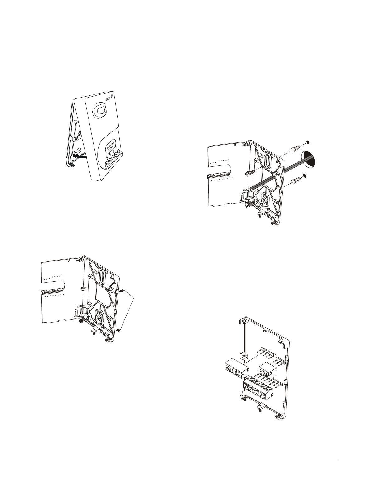
Note: PIR models have a wiring connection between
Figure 1: Removing the
Thermostat Controller Cover
(T600HCx-4+PIR Model Shown)
FIG:cvr_ rmvl
Figure 2: Opening the
Thermostat Controller PCB
FIG:prntd_ crct_br d
Tabs
Figure 3: Securing the Thermostat Controller
Mounting Base to the Wall
FIG:mntng_bs
Figure 4: Removing the Screw Terminal Blocks
the cover and the Printed Circuit Board (PCB). This
connection allows for proper wiring of the occupancy
sensor. Carefully remove the wiring connection from
the PCB by pulling up on the connector block. Do not
attempt to remove the connector block by pulling on the
wires.
6. Drill a 3/16 in. (5 mm) hole at each of the two
marked locations and tap nylon anchors (included
with the thermostat controller) flush to the wall
surface.
Note: Other means of anchoring the device may be
desired, depending on the wall medium.
7. Position the thermostat controller mounting base
on the wall and use the two mounting screws
(included with the thermostat controller) to secure
the base to the wall surface as illustrated in
Figure 3.
Note: Be careful not to overtighten the mounting
screws.
3. Carefully pull the locking tabs on the right side of
the thermostat controller mounting base and
unlock the PCB. Open the PCB to the left as
illustrated in Figure 2.
PCB
Locking
4. Pull approximately 6 in. (152 mm) of wire from the
wall and insert the wire through the hole in the
thermostat controller mounting base.
5. Align the thermostat controller mounting base on
the wall and use the base as a template to mark
the two mounting hole locations.
Note: Be sure to position the thermostat controller
mounting base so that the arrow on the base points
upward to indicate the top of the thermostat controller.
8. Swing the PCB back to the right and carefully snap
it into the locking tabs on the thermostat controller
mounting base.
9. Remove the screw terminal blocks that are
attached to a disposable adhesive. Figure 4
illustrates the locations of the screw terminal
blocks on the thermostat controller.
s
k
c
l
b
_
l
n
m
r
t
:
G
I
F
T600HCx-4 and T600HCx-4+PIR Series Single-Stage Thermostat Controllers Installation Instructions2
Page 3
Wiring
!
!
Figure 5: Terminal Blocks
Y1 G RC
C
2
34
5
67
RS
OS
MS
AUX
FIG:T600HCx_trmblk
When an existing thermostat controller is replaced,
remove and label the wires to identify the terminal
functions. When a T600HCx-4 or T600HCx-4+PIR
Series Thermostat Controller is replaced, simply
remove the old screw terminal blocks and reinsert them
onto the PCB of the replacement thermostat controller .
CAUTION: Risk of Electric Shock.
Disconnect power supply before making
electrical connections to avoid electric
shock.
CAUTION: Risk of Property Damage.
Do not apply power to the system before
checking all wiring connections. Short
circuited or improperly connected wires
may result in permanent damage to the
equipment.
IMPORTANT: Make all wiring connections in
accordance with local, national, and regional
regulations. Do not exceed the electrical ratings of
the T600HCx-4 or T600HCx-4+PIR Series
Thermostat Controller.
To wire the thermostat controller:
1. Strip the ends of each wire a 1/4 in. (6 mm) and
connect them to the appropriate screw terminals as
indicated in Figure 5.
Four-Pole
Left Top Conne ctor
Seven-Pol e Bot tom Connector
DI1 DI2
10 11 12 14
2. Carefully push any excess wire back into the wall.
Two-Pole
Right Top
Connector
RH W1
Scom
15
1613
Note: Seal the hole in the wall with fireproof material
to prevent drafts from affecting the ambient
temperature readings.
3. Reinsert the screw terminal blocks onto the PCB.
Note: If multiple wires are inserted into the terminals,
be sure to properly twist the wires together prior to
inserting them into the terminal connectors.
4. For PIR models, carefully reattach the PIR
connector to the PCB.
5. Reattach the thermostat controller cover to the
mounting base (top side first).
6. Use a Phillips-head screwdriver to install the
security screw on the bottom of the thermostat
controller cover if desired. The security screw
comes packaged separately in a plastic bag with
the thermostat controller.
Table 1: Terminal Identification (See Figure 5.)
Terminal
Number
2
3
4 RC 24 VAC from Equipment
5 C 24 VAC (Common) from
6 RH 24 VAC for Heating Stage
7
10
11 DI1 Configurable Digital Input 1
12 DI2 Configurable Digital Input 2
13 RS Remote Room Temperature
14 Scom Sensor Common
15 OS Outside Air Temperature Sensor
16 MS Not Used
1. This terminal provides the voltage from RC through a
relay contact.
2. This terminal provides the voltage from RH through a
relay contact.
Terminal
Label
1
Y1
1
G
2
W1
1
AUX
Function
Energizes on a Call for Cooling
Energizes Fan in Accordance
with Selected Fan Mode
Transformer
Equipment Transformer
Energizes on a Call for Heating
Auxiliary Output
Sensor
T600HCx-4 and T600HCx-4+PIR Series Single-Stage Thermostat Controllers Installation Instructions 3
Page 4
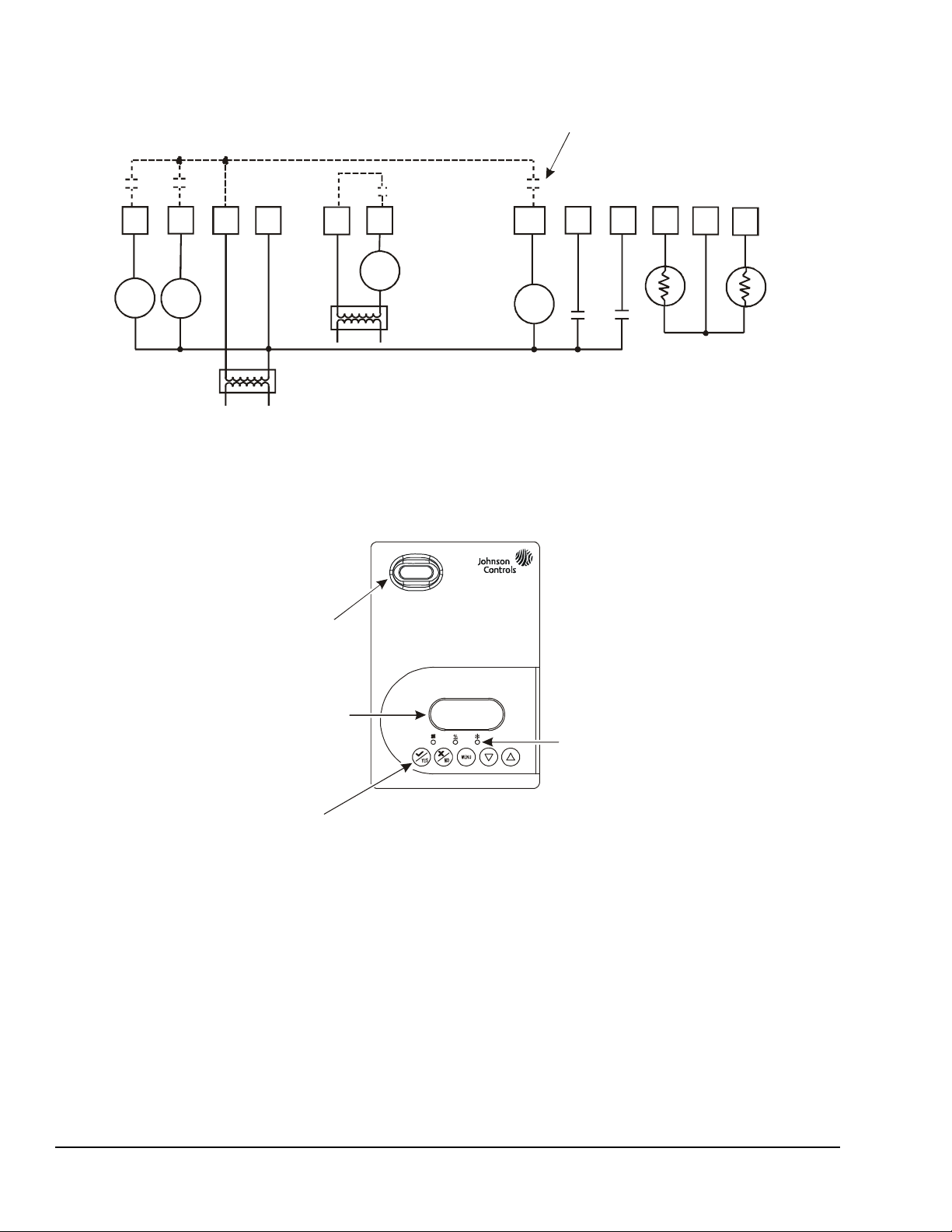
Figure 6: Wiring the T600HCx-4 or T600HCx-4+PIR Series The rmostat Controller
Cool 1
Fan
24 VAC
Thermostat Controller
Power
Heat 1
Y1
GRCC
RH W1
AUX
DI1
DI2
RS
Note: If the same power source is used
loads, install a jumper across RC and RH.
Remote
Room
Sensor
Outside
Air
Sensor
- Lighting
- On/Off Actuation
- Exhaust Fan
Figure 7: Front Cover of Thermostat Controller (T600HCx-4+PIR Model Shown)
70.0ºF
Backlit, plain text
Liquid Crystal Display (LCD)
is easy to read in any condition.
Five keys on the thermostat controller
make ope ra t ion easy and intui t ive.
indicate system activity.
FIG:frnt_v w
PIR motio n de te ct or
saves ene r gy using
standby setpoints.
Independent Contact
Scom
OS
Aux
for the thermostat controller and the heating
Setup and Adjustments
Thermostat Controller Operation Overview
Room Temp
Temperature
Light-Emitting Diodes (LEDs)
Temperature
FIG:T600HCx_wrng
Thermostat Controller User Interface Keys
The T600HCx-4 and T600HCx-4+PIR Series
Thermostat Controller user interface consists of five
keys on the front cover (as illustrated in Figure 7). The
function of each key is as follows:
•Use the YES key to:
- confirm menu selections and to advance to the
next menu item.
T600HCx-4 and T600HCx-4+PIR Series Single-Stage Thermostat Controllers Installation Instructions4
- stop the Status Display Menu from scrolling
and to manually scroll to the next parameter on
the menu.
Note: When the thermostat controller is left
unattended for 45 seconds, the thermostat controller
display resumes scrolling.
•Use the NO key to decline a parameter change and
to advance to the next menu item.
Page 5

•Use the MENU key to:
• System Mode
- access the Main User Menu or exit the menu
- access the Installer Configuration Menu or to
exit the menu (See Configuring the
or T600HCx-4+PIR Series Thermostat
Controller on page 6.)
•Use the UP/DOWN arrow keys to change the
configuration parameters and to activate a setpoint
adjustment.
T600HCx-4
Backlit LCD
The T600HCx-4 and T600HCx-4+PIR Series
Thermostat Controllers include a 2-line, 8-char ac te r
backlit display. Low-level backlighting is present during
normal operation, and it brightens when any user
interface key is pressed. The backlight returns to low
level when the thermostat controller is left unattended
for 45 seconds.
LEDs
Three LEDs are included to indicate the fan status, call
for heat, or call for cooling:
• The fan LED is on when the fan is on.
• The heat LED is on when heating is on.
• The cool LED is on when cooling is on.
Integrated PIR Sensor – T600HCx-4+PIR Series Thermostat Controllers
The integrated PIR sensor allows for automatic
switching between fully adjustable Occupied and
Unoccupied temperature setpoints without user
interaction. This feature generates incremental energy
savings during scheduled occupied periods while the
space is unoccupied.
Programming Overview
Three menus are used to view, program, and configure
the T600HCx-4 and T600HCx-4+PIR Ser i es
Thermostat Controllers: the Status Display Menu, the
Main User Menu, and the Installer Configuration Menu.
Status Display Menu
The Status Display Menu is displayed during normal
thermostat controller operation, and continuously
scrolls through the following parameters:
• Room Temperature
• Day and Time (T600HCP-4 and T600HCP-4+PIR
Models)
• Schedule Status
(Occupied/Unoccupied/Override [PIR Models])
• Outside Temperature – An outside air temperature
sensor must be installed and connected.
• Applicable Alarms – The backlight lights up as an
alarm condition is displayed.
Note: Press the YES key to temporarily stop this
menu from scrolling.
Note: An option is available within the Installer
Configuration Menu to lock out the scrolling display and
show only the Room Temperature parameter.
Main User Menu
Use the Main User Menu to access and change the
basic operating parameters of the ther mostat controller .
Access the menu by pressing the MENU key during
normal thermostat controller operation.
Installer Configuration Menu
Use the Installer Configuration Menu to set up the
thermostat controller for application-specific operation.
To access the menu, press and hold the MENU key for
approximately 8 seconds.
Occupancy Sensor Operation – T600HCx-4+PIR Series Thermostat Controllers
A T600HCx-4+PIR Series Thermostat Controller (or a
T600HCx-4 Series Thermostat Controller equipped
with a PIR accessory cover) provides advanced
occupancy logic.
Note: The PIR strategy is an occupied strategy. If the
thermostat controller is programmed to be Unoccupied ,
the PIR function does not have an affect on the
occupancy strategy.
The thermostat controller automatically switches the
occupancy level between Occupied and Unoccupied as
required, when local movement is sensed. In the
Occupied mode, if no movement is detected beyond
the Unocc TM parameter setting, the mode changes to
Unoccupied. Once movement is detected, the mode
changes back to Occupied.
Occupancy sensing is enabled only if a PIR cover is
installed. The PIR cover, when installed, is auto
detected.
PIR Diagnostic LEDs
The diagnostic LEDs inside the PIR lens brighten when
movement is detected within the first 30 minutes after
powerup. The LEDs do not light up or brighten after the
initial 30-minute period.
T600HCx-4 and T600HCx-4+PIR Series Single-Stage Thermostat Controllers Installation Instructions 5
Page 6
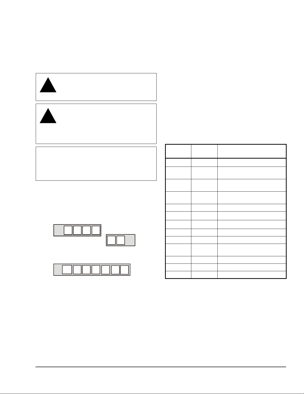
Setpoints
Figure 8: Increasing Room Temperature Setpoints
Occ Heat
= 72°F
Occ Cool
= 75°F
Unocc Heat
= 65°F
Room Temperature
FIG:rm_tmp
The installer must be certain that the difference
between the Occupied and Unoccupie d se tpo i n ts can
be recovered within a timely fashion to ensure
occupancy comfort. In addition, the difference between
the two setpoints must be large enough to warrant
maximum energy savings.
These setpoints and Unoccupied timers are adjustab le
to allow for customization, as dictated by the individual
space requirements. See Figure 8 for an example of
increasing room temperature setpoints.
Configuring the T600HCx-4 or T600HCx-4+PIR Series Thermostat Controller
The T600HCx-4 and T600HCx-4+PIR Series
Thermostat Controllers come from the factory with
default settings for all configurable parameters. The
default settings are shown in Table 2. To reconfigure
the parameters via the thermostat controller, follow the
steps in this section.
1. To access the Installer Configuration Menu,
press and hold the MENU key for ap pr ox ima te ly
8 seconds.
Note: If the Password parameter is configured,
Password 0 appears on the thermostat controller
display indicating that the configured password is
required to proceed. Use the UP/DOWN arrow keys to
indicate the configured password, then press the
YES key to proceed through the Installer Con figuration
Menu parameters.
2. Once the Installer Configuration Menu begins,
press the NO key to scroll through the parameters
listed in Table 2.
Table 2: Installer Configuration Menu (Part 1 of 6)
Parameter
Appearing
on Display
Pswrd Sets the protective access
Description and Default Selection Options
Range: 0 to 1,000
password to prevent unauthorized
access to the Installer Configuration
Menu.
Default: 0
Note: The default setting does not
lock out access to the Installer
Configuration Menu.
3. When the desired parameter is displayed, use the
YES key to choose the desired selection option.
4. Press the YES key and then the NO key to
continue scrolling through the parameters.
To exit the Installer Configuration Menu at any time,
press the MENU key, then at the exit prompt, press the
YES key. To pass over a parameter without changing it,
press the NO key.
When the thermostat controller is in the Installer
Configuration Menu and left unattended for
approximately 8 seconds, the thermostat controller
reverts to the Status Display Menu.
Configuring Inputs DI1 and DI2
When DI1 and DI2 are configured for an alarm
condition, an alarm condition is displayed locally when
the input is closed. An alarm message is included on
the scrolling Status Display Menu and when the
message is displayed, the backlight momentarily
lights up.
Each input can be configured to the Selection Options
included in Table 2.
T600HCx-4 and T600HCx-4+PIR Series Single-Stage Thermostat Controllers Installation Instructions6
Page 7

Table 2: Installer Configuration Menu (Part 2 of 6)
Parameter
Description and Default Selection Options
Appearing
on Display
1
DI1
1
DI2
MenuScro Gives the option of having the
Configuration of Digital Input 1.
Default: None
Configuration of Digital Input 2.
Default: None
display continuously scroll the
parameters.
Default: on
(None): No function is associated with an input.
(Service): A Service alarm is displayed on the thermostat controller
when the input is energized. Tie this input into the air conditioning
unit control card, which provides an alarm if a malfunction occurs.
(Filter): A Filter alarm is displayed. This alarm can be connected to
a differential pressure switch that monitors a filter.
(RemOVR): Temporary occupancy request via a remote input. This
override function is controlled by a manual remote occupancy
override. When enabled, this condition disables the override
capability of the thermostat controller.
(RemNSB): Remote Night Setback (NSB) via a time clock input, an
occupancy sensor, or from a voltage-free contact.
Contact open = Occupied; contact closed = Unoccupied.
(Fan lock): A backlit flashing Fan lock alarm is displayed on the
thermostat controller when the input is not energized. This alarm is
used in conjunction with a local airflow sensor connected to the
input. The thermostat controller heating or cooling action is locked
out if no airflow is detected 10 seconds after the fan (Terminal G) is
energized. Contact open = no airflow; contact closed = airflow
present.
(off): The scroll is inactive.
(on): The scroll is active.
T600HCx-4 and T600HCx-4+PIR Series Single-Stage Thermostat Controllers Installation Instructions 7
Page 8

Table 2: Installer Configuration Menu (Part 3 of 6)
Parameter
Description and Default Selection Options
Appearing
on Display
Lockout Selectable Lockout Levels for
limiting end-user keypad interaction.
Default: 0
Pwr del
3
Sets the delay time period at
thermostat controller powerup, or
each time power is removed and
reapplied, before any operation
(fan, heating, or cooling) is
authorized. Also can be used to
sequence the startup of multiple
units in one location.
Default: 10.0 sec
Frost pr Pro v ides a minimum heating
setpoint of 42.0°F/5.5°C to prevent
freezing in the zone controlled by
the thermostat controller.
Default: off
Heat max
4
Sets the Occupied and Unoccupied
maximum Heating setpoint values.
Default: 90.0°F/32.0°C
Cool min
4
Sets the Occupied and Unoccupied
minimum Cooling setpoint values.
Default: 54.0°F/12.2°C
Function Lockout Level
Occupancy
Override
Permanent
T emperature
Setpoints
T emporary
T emperature
Setpoints
System Mode
Setting
Fan Mode Setting Access No Access No Access
Schedules
Setting
Clock Setting
Permanent Hold
Range: 10.0 to 120.0 sec
(on): Enabled
(off): Disabled
Range: 40.0°F/4.5°C to 90.0°F/32.0°C
Range: 54.0°F/12.2°C to 100.0°F/37.7°C
(0) (1) (2)
Access Access No Access
Access No Access No Access
Access Access No Access
Access No Access No Access
Access No Access No Access
2
2
Access Access Access
2
Access No Access No Access
T600HCx-4 and T600HCx-4+PIR Series Single-Stage Thermostat Controllers Installation Instructions8
Page 9

Table 2: Installer Configuration Menu (Part 4 of 6)
Parameter
Description and Default Selection Options
Appearing
on Display
Pband Sets the proportional band used by
the thermostat controller
Proportional-Integral (PI) control
loop.
Default: 2.0F°/1.1C°
Note: The proportional band
default setting of 2.0F°/1.1C°
provides satisfactory thermostat
controller operation in most
instances. A proportional band
setting other than the default is
normally used in installations where
the location of the thermostat
controller is problematic, leading to
unwanted cycling. An example of a
problematic installation is a
wall-mounted thermostat controller
installed between the return and
supply air feeds, that is directly
influenced by the supply air stream.
Anticycl Anti-Short Cycle timer sets the
minimum on/off times for heating
and cooling.
Default: 2.0 min
Note: Set the anti-short cycle timer
to 0.0 min for equipment that
already has its own anti-short cycle
timer.
Heat cph Sets the maximum number of
Heating cycles per hour.
Default: 4.0
Cool cph Sets the maximum number of
Cooling cycles per hour.
Default: 4.0
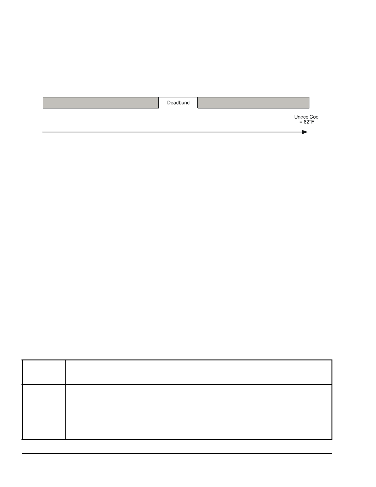
Deadband Sets the minimum deadband
between the heating and cooling
setpoints.
Default: 2.0F°/1.0C°
Fan cont Determines how the fan is activated
in response to a call for heating.
Default: on
Note: The Fan cont parameter
applies to W1 when the fan is in the
Auto mode only. The Fa n co nt
parameter does not affect fan
operation on a call for cooling (Y1).
Fan del Fan delay extends fan operation
after a heating or cooling cycle has
ended.
Default off
Note: The fan delay is only active
when the fan is in the Auto mode.
(2): 2.0F°/1.1C°
(3): 3.0F°/1.7C°
(4): 4.0F°/2.2C°
(5): 5.0F°/2.8C°
(6): 6.0F°/3.3C°
(7): 7.0F°/3.9C°
(8): 8.0F°/4.4C°
Range: 0.0 to 5.0 min adjustable in 1-minute increments
Range: 3.0 to 8.0 cycles per hour
Range: 3.0 or 4.0 cycles per hour
Range: 2.0F°/1.0C° to 4.0F°/2.0C° adjustable in 1.0F°/0.5C°
increments
(off): The thermostat controller does not activate the fan in
response to a call for heating. The fan is activated by the equipment
fan and limit control.
(on): Enables the thermostat controller to activate the fan in
response to a call for heating.
(on): Extends fan operation by 60 seconds after a heating or cooling
cycle has ended.
(off): No extension of fan operation after a heating or cooling cycle
has ended.
T600HCx-4 and T600HCx-4+PIR Series Single-Stage Thermostat Controllers Installation Instructions 9
Page 10

Table 2: Installer Configuration Menu (Part 5 of 6)
Parameter
Description and Default Selection Options
Appearing
on Display
TOccTime Sets the duration of the Temporary
Occupancy Time (when the
thermostat controller is in the
Unoccupied mode) when a
Schedule Override Function is
enabled using either the Main User
Menu or DI1 or DI2 configured as a
temporary override remote contact
(RemOVR).
Sets the effective duration of the
Temporary heating or cooling
setpoints set using the
UP/DOWN arrow keys.
Default: 3.0 hrs
Cal RS Sets the desired room air
Cal OS Sets the desired outside air
H lock Disables heating stage(s) operation
C lock Disables cooling stage(s) operation
Unocc TM Sets the time delay between the
2/4event
2
temperature sensor calibration
(offset). The offset can be added to
or subtracted from the actual
displayed room temperature.
Default: 0.0F°/0.0C°C
temperature sensor calibration
(offset). The offset can be added to
or subtracted from the actual
displayed room temperature.
Default: 0.0F°/0.0C°
when the outside air temperature is
greater than the configured value. If
the fan mode is set to Auto or
Smart, the fan output is also
disabled. Requires that an outside
air temperature sensor be installed
and connected.
Default: 120°F/49°C
when the outside air temperature is
less than the configured value. If the
fan mode is set to Auto or Smart,
the fan output is also disabled.
Requires that an outside air
temperature sensor be installed and
connected.
Default: -40°F/-40°C
moment when the thermostat
controller toggles from the Occupied
mode to the Unoccupied mode after
the last motion is detected by the
occupancy sensor.
Default: 0.5 hours
Sets the number of events within a
24-hour period.
Default: 2.0
Range: 0.0 to 12.0 hrs adjustable in 1-hour increments
Range: -5.0F°/-2.5C° to 5.0F°/2.5C° adjustable in 1.0F°/0.5C°
increments
Range: -5.0F°/-2.5C° to 5.0F°2.5C° adjustable in 1.0F°/0.5C°
increments
Range: -15°F/-26°C to 120°F/49°C adjustable in 5F°/5C° increments
Range: -40°F/-40°C to 95°F/35°C adjustable in 5F°/5C° increments
Range: 0.5 hours to 24.0 hours adjustable in 0.5 hour increments
(4.0): Four events (two Occupied and two Unoccupied) within a
24-hour period
(2.0): Two events (one Occupied and one Unoccupied) within a
24-hour period
T600HCx-4 and T600HCx-4+PIR Series Single-Stage Thermostat Controllers Installation Instructions10
Page 11

Table 2: Installer Configuration Menu (Part 6 of 6)
Parameter
Description and Default Selection Options
Appearing
on Display
Aux cont Energizes peripheral devices
(lighting equipment, exhaust fans,
and economizers).
Default: n.o.
Note: The contact toggles with the
internal Occupied/Unoccupied
schedule (or the NSB contact on
one of the digital inputs, if used).
Prog rec
1. Setting DI1 or DI2 to RemNSB disables schedules and stops the Schedule menu display. Any other setting enables
2. T600HCP-4 and T600HCP-4+PIR models.
3. When adjusting the numeric value, press the UP/DOWN arrow key to change the value by single increments; press and
4. When adjusting the temperature, press the UP/DOWN arrow key to change the value in 0.5F°/0.5C° increments; press and
2
schedules and the Schedule menu (T600HCP-4 and T600HCP-4+PIR models).
hold the UP/DOWN arrow key to change the numeric value in increments of ten.
hold the UP/DOWN arrow key to change the value in 5.0F°/5.0C° increments.
Provides the desired occupied
temperature either at the start of the
Occupied schedule or after the
Occupied schedule begins.
Default: off
Note: Progressive recovery is
disabled if either DI1 or DI2 is
configured as remote NSB.
(n.c.): Contact open = Occupied; contact closed = Unoccupied
(n.o.): Contact closed = Occupied; contact open = Unoccupied
(on): Enabled (provides the desired Occupied temperature at the
start of the Occupied schedule)
(off): Disabled (provides the desired Occupied temperature after the
Occupied schedule begins)
T600HCx-4 and T600HCx-4+PIR Series Single-Stage Thermostat Controllers Installation Instructions 11
Page 12

Operation
75.0 °F
schd Y/N
ovrd Y/N
set? Y/N
set? Y/N
set? Y/N
set? Y/N
set? Y/N
hold? Y/N
Setup/Operation of the T600HCx-4 or T600HCx-4+PIR Series Thermostat Controller
Once the thermostat controller is configured via the
Installer Configuration Menu, set up its operating
parameters via the Main User Menu. Access this menu
by pressing the MENU key during normal thermostat
controller operation. The Main User Menu contains th e
basic operating features of the thermostat controller.
The Main User Menu also uses Auto Help, which is
displayed automatically in the menu when there is a
pause in setup activity . To exit Auto Help, continue with
the setup selection. When the thermostat controller is
in the Main User Menu and is left unattended for
45 seconds, the menu reverts to the Status Display
Menu.
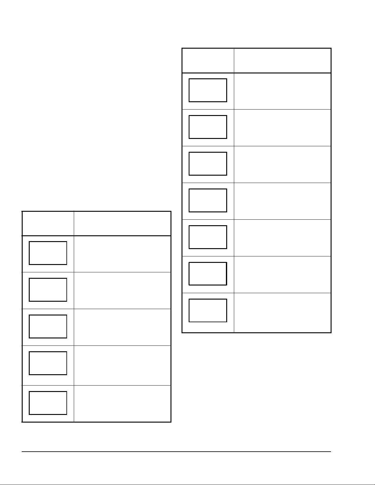
Follow the steps in Table 3 to set up the thermostat
controller.
Table 3: Setting Up the T600HCx-4 or
T600HCx-4+PIR Series Thermostat
Controller (Part 1 of 2)
Thermostat
Controller
Display
RoomTemp
Description
Press the MENU key while in the
Status Display Menu to enter the
Main User Menu.
Table 3: Setting Up the T600HCx-4 or
T600HCx-4+PIR Series Thermostat
Controller (Part 2 of 2)
Thermostat
Description
Controller
Display
Selects the Fan Mode
Fan mode
Schedule
Clock
Schedule
Default: Automatic (auto) for
T600HCN-4 and T600HCN-4+PIR
Models
Smart (smart) for T600HCP-4 and
T600HCP-4+PIR Models
See Selecting the Fan Mode
14.
Sets the Occupied and Unoccupied
Time Periods
Programming the Daily
See
Schedule – Two-Event (T600HCP-4
and T600HCP-4+PIR Models) on
page 15 and
Schedule – Four-Event (T600HCP-4
and T600HCP-4+PIR Models) on
page 16.
Sets the Day and Time
Setting the Day and Time
See
(T600HCP-4 and T600HCP-4+PIR
Models) on page 17.
Sets a Permanent Hold on the
Schedule or Resumes the Schedule
See
Setting Schedule Hold on page
17.
Programming the Daily
on page
Override
Cancel
Temperat
Sys mode
Overrides Unoccupied Setpoints
Only Appears if Thermostat
Controller is in Unoccupied State
See Enabling Te mporary Override
Schedule on page 12.
Cancels Override Mode
Sets the Temperature Setpoints
See Entering Permanent
Temperature Setpoints on page 13.
Selects the System Mode
Default: Automatic (auto)
See Selecting the System Mode
page 14.
on
Note: Schedule Set and Clock Set are available on
the T600HCP-4 and T600HCP-4+PIR models only.
Enabling Temporary Override Schedule
Note: The Override Schedule function is available on
the T600HCN-4 and T600HCN-4+PIR models only
when DI1 or DI2 is configured as remote NSB.
Note: The Override Schedule prompt only appears
when in the Unoccupied (Unoccup) or Unoccupied
Hold (Unoccup hold) mode.
The override schedule prompt only appears when the
thermostat controller is in the Unoccupied state. This
menu selection gives the user the option of overriding
the Unoccupied setpoints with the Occupied setpoints
for the amount of time specified under the TOccTime
parameter. See Configuring the
T600HCx-4+PIR Series Thermostat Controller on p age
6.
Note: If DI1 or DI2 is configured to operate as a
remote override contact, this menu is disabled.
T600HCx-4 or
T600HCx-4 and T600HCx-4+PIR Series Single-Stage Thermostat Controllers Installation Instructions12
Page 13

To override the Unoccupied state while in the Main
75.0°F
set? Y/N
set? Y/N
75.0°F
set? Y/N
68.0°F
set? Y/N
80.0°F
User Menu:
1. Press the NO key for all prompts until the Override
Schedule prompt appears. If the thermostat
controller is in the Unoccupied state, this is the first
prompt.
2. Press the YES key to enable the temporary
override. The thermostat controller returns to the
Status Display Menu.
When scrolling through the Status Display Menu,
Override now appears for the schedule status
parameter.
Canceling the Temporary Override
The Cancel Override (Cancel ovrd) prompt only
appears when the thermostat controller is in the
Unoccupied override mode.
To resume the schedule while in the Main User Menu:
1. Press the NO key for all prompts until the Cancel
ovrd prompt appears. If the thermostat controller is
in the override state, this is the first prompt.
2. Press the YES key to resume the programmed
schedule.
The thermostat controller returns to the Status Display
Menu.
Entering Permanent Temperature Setpoints
The first prompt appearing in the Main User Menu of
the thermostat controller when in the Occupied state
sets the permanent temperature setpoint.
To enter the permanent heating and cooling setpoints
for the Occupied and Unoccupied modes, follow the
steps in Table 4. When changing the temperatures,
press and release the keys to change the temperature
in 0.5F°/0.5C° increments; press and hold down the
keys to change the temperature in 5.0F°/5.0C°
increments.
Table 4: Entering Permanent Temperature
Setpoints (Part 1 of 2)
Thermostat
Description
Controller
Display
Press the MENU key while in the
RoomTemp
Temperat
Cooling
Cooling
Heating
Status Display Menu to enter the
Main User Menu.
Press the NO key for all prompts until
the temperature setpoint prompt
appears on the display (it may be the
first prompt). Press the YES key to
enter the temperature setting menu.
Press the YES key to change the
Occupied cooling setpoint. Press the
NO key to advance to the Occupied
heating setpoint menu.
Press the UP/DOWN arrow keys to
set the temperature. Press the
YES key to store the value and
advance to the next menu.
Press the YES key to change the
Occupied heating setpoint. Press the
NO key to advance to the
Unoccupied cooling setpoint menu.
Press the UP/DOWN arrow keys to
Heating
Unocc CL
Unocc CL
set the temperature. Press the
YES key to store the value and
advance to the next menu.
Press the YES key to change the
Unoccupied cooling setpoint. Press
the NO key to advance to the
Unoccupied heating setpoint.
Press the UP/DOWN arrow keys to
set the temperature. Press the
YES key to store the value and
advance to the next menu.
T600HCx-4 and T600HCx-4+PIR Series Single-Stage Thermostat Controllers Installation Instructions 13
Page 14

Table 4: Entering Permanent Temperature
set? Y/N
62.0°F
C
set? Y/N
Y/N
Setpoints (Part 2 of 2)
Thermostat
Description
Controller
Display
Press the YES key to change the
Unocc HT
Unoccupied heating setpoint. Press
NO key to advance to the
the
temperature display units.
2. Press the YES key to cancel all temporary
setpoints.
3. Press the MENU key again and press the YES key
to exit the Main User Menu.
The setpoint reverts to the Permanent Temperature
Setpoint.
Selecting the System Mode
The thermostat controller has four system modes:
UP/DOWN arrow keys to
YES key to set the display
NO key to
YES key to return to the
Unocc HT
°F/°
Exit?
Press the
set the temperature. Press the
YES key to store the value and
advance to the next menu.
Press the
units to °F or °C. Press the
advance to the temperature setpoint
type menu.
Press the
Status Display Menu or press the
NO key to re-enter the temperature
setting menu.
Entering Temporary Temperature Setpoints
The user can temporarily change the temperature
setpoints for the Occupied and Unoccupied heating
and cooling modes. To temporarily change the setpoint,
press the UP/DOWN arrow keys to change the
temporary setpoint for the current mode of operation.
Note: Whether the thermostat controller is heating or
cooling, the respective setpoint is temporarily adjusted.
To toggle between the temporary heating and cooling
setpoints, press the NO key while changing the
temporary setpoints.
Ending Temporary Temperature Setpoints
The temporary setpoints remain in effect for the
duration set in the TOccTime parameter or until
manually released.
Note: Setting the TOccTime parameter to 0.0 hrs
prevents the temporary setpoints from taking effect.
To manually release the temporary setpoint, while in
the Main User Menu:
1. Press the NO key for all prompts until the Temperat
set prompt appears. If the thermostat controller is
in the Occupied state, this is the first prompt.
• Automatic Mode (auto): Automatic changeover
between heating and cooling. This is the default
setting.
• Cooling Mode (cool): Cooling operation only.
• Heating Mode (heat): Heating operation only.
• Off Mode (off): The thermostat controller is off;
however, when the frost protection
(Frost pr parameter) is enabled, the thermostat
controller still calls for heat if the temperature falls
below 42°F/5.5°C.
To set the system mode while in the Main User Menu:
1. Press the NO key for all prompts until the system
mode prompt appears on the display. Press the
YES key to select the desired system mode.
2. Press the UP/DOWN arrow keys to locate the
desired system mode. Press the YES key to select
the desired system mode.
3. Press the YES key to return to the Status Display
Menu or press the NO key to return to the system
mode selection menu.
Selecting the Fan Mode
The thermostat controller has three fan mode settings:
• On Fan Mode (on): Energizes the fan all the time
for both Occupied and Unoccupied states, even if
the system mode is set to off.
• Automatic Fan Mode (auto): Energizes the fan
only on a call for heating or cooling, for both
Occupied and Unoccupied states. This is the
default setting for the T600HCN-4 and
T600HCN-4+PIR models.
Note: The setting for the Fan cont parameter may
affect the fan operation on a call for heating.
• Smart Fan Mode (smart): Energizes the fan all
the time for Occupied states, and only on a call for
heating or cooling in Unoccupied states. This is the
default setting for the T600HCP-4 and
T600HCP-4+PIR models.
T600HCx-4 and T600HCx-4+PIR Series Single-Stage Thermostat Controllers Installation Instructions14
Page 15

To select the fan mode while in the Main User Menu:
75.0°F
set? Y/N
y
set? Y/N
day? Y/N
12:00 AM
12:00 AM
y
set? Y/N
previous
set? Y/N
Y/N
1. Press the NO key for all prompts until the fan mode
prompt appears on the display. Press the YES key
to set the fan mode.
2. Press the UP/DOWN arrow keys to locate the
desired fan mode. Press the YES key to select the
desired fan mode.
3. Press the YES key to return to the Status Display
Menu or press the NO key to return to the fan
mode selection menu.
Programming the Daily Schedule – Two-Event (T600HCP-4 and T600HCP-4+PIR Models)
The schedule-setting menu is used to enter the
Occupied or Unoccupied states for each day of the
week. The schedule-setting menu reflects either a
two- or a four-event schedule per day, based on what
was selected in the 2/4event parameter during the
configuration process. If the schedule-setting menu
does not reflect a two-event schedule, select two
events in the 2/4event parameter of the Installer
Configuration Menu.
When changing the time, press and release the
UP/DOWN arrow keys to change the time in 1-minute
increments; press and hold down the keys to change
the time in 30-minute increments.
Note: Programming one of the digit al input s to remo te
NSB disables the menu.
Table 5: Programming the Daily Schedule –
Two-Event (Part 2 of 2)
Thermostat
Description
Controller
Display
Press the YES key to set the
Monda
Occupied
Occupied
Unoccup
Tuesda
schedule for Monday or press the
NO key to advance to Tuesday.
Press the YES key to set the
Occupied start time for Monday or
press the NO key to advance to
Tuesday. Selecting NO leaves the
thermostat controller in the
Unoccupied state for the entire day.
Press the UP/DOWN arrow keys to
set the Occupied start time. Press the
YES key to enter the time.
Press the UP/DOWN arrow keys to
set the Unoccupied start time. Press
the YES key to enter the time.
Press the YES key to set the
schedule for Tuesday or press the
NO key to advance to Wednesday.
To set the time schedule for a two-event schedule,
follow the steps in Table 5. See T able7, Events 1
and 2, for an example of a two-event office schedule.
Table 5: Programming the Daily Schedule –
Two-Event (Part 1 of 2)
Thermostat
Description
Controller
Display
Press the MENU key while in the
RoomTemp
Schedule
Sta tus Disp la y Me nu to ent er th e
Main User Menu.
Press the
the schedule set prompt appears on
the display. Press the
enter the scheduling menu.
NO key for all prompts until
YES key to
CopyY/N
Wednesda
Exit?
Press the YES key to copy the
schedule from the previous day.
Press the NO key to set a different
schedule.
If the YES key was pressed, the next
prompt is for Wednesday. Repeat the
procedure for the rest of the days of
the week.
After setting the schedule for all the
days of the week, following the last
entry for Sunday, press the YES key
to return to the Status Display Menu
or press the NO key to start again at
Monday.
T600HCx-4 and T600HCx-4+PIR Series Single-Stage Thermostat Controllers Installation Instructions 15
Page 16
Programming the Daily Schedule – Four-Event
75.0°F
set? Y/N
set? Y/N
day? Y/N
12:00 AM
12:00 AM
12:00 AM
12:00 AM
y
set? Y/N
previous
set? Y/N
Y/N
(T600HCP-4 and T600HCP-4+PIR Models)
The schedule-setting menu is used to enter the
Occupied and Unoccupied states for each day of the
week. The schedule-setting menu reflects either a
two- or four-event schedule per day, based on what
was selected in the 2/4event parameter during the
configuration process. If the schedule-setting menu
does not reflect a four-event schedule, select four
events in the 2/4event parameter of the Installer
Configuration Menu.
When changing the time, press and release the
UP/DOWN arrow keys once to change the time in
1-minute increments; press and hold down the keys to
change the time in 30-minute increments.
Note: Programming one of the digital in puts to remote
NSB disables the menu.
To set the time schedule for a four-event schedule,
follow the steps in Table 6. See Tab le 7 for an example
of a four-event office schedule.
Table 6: Programming the Daily Schedule –
Four-Event (Part 1 of 2)
Thermostat
Controller
Display
RoomTemp
Schedule
Monday
Description
Press the MENU key from the Status
Display Menu to enter the Main User
Menu.
Press the NO key for all prompts until
the schedule set prompt appears on
the display. Press the YES key to
enter the scheduling menu.
Press the YES key to set the
schedule for Monday or press the
NO key to advance to Tuesday.
Table 6: Programming the Daily Schedule –
Four-Event (Part 2 of 2)
Thermostat
Description
Controller
Display
Press the UP/DOWN arrow keys to
Unoccup
Occupie2
Unoccup2
Tuesda
CopyY/N
Wednesda
Exit?
set the first Unoccupied start time.
Press the YES key to enter the time.
Press the UP/DOWN arrow keys to
set the second Occupied start time.
Press the YES key to enter the time.
Press the UP/DOWN arrow keys to
set the second Unoccupied start
time. Press the YES key to enter the
time.
Press the YES key to set the
schedule for Tuesday or press the
NO key to advance to Wednesday.
Press the YES key to copy the
schedule from the previous day.
Press the NO key to set a different
schedule.
If the YES key was pressed, the next
prompt is for Wednesday. Repeat the
procedure for all days of the week.
After setting the schedule for all the
days of the week, following the last
entry for Sunday, press the YES key
to return to the Status Display Menu
or press the NO key to start again at
Monday.
Occupied
Occupied
T600HCx-4 and T600HCx-4+PIR Series Single-Stage Thermostat Controllers Installation Instructions16
Press the YES key to set the
Occupied start time for Monday or
press the NO key to advance to
Tuesday. Selecting NO leaves the
thermostat controller in the
Unoccupied state for the entire day.
Press the UP/DOWN arrow keys to
set the first Occupied start time.
Press the YES key to enter the time.
Page 17
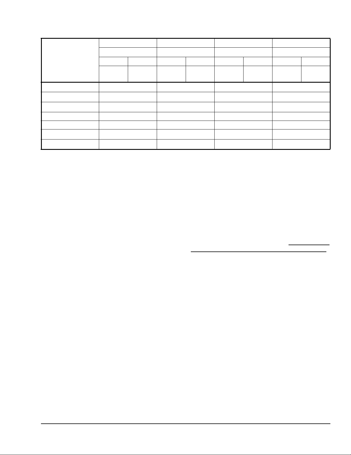
Table 7: Four-Event Office Schedule
Event 1 Event 2 Event 3 Event 4
Occupied Unoccupied Occupied 2 Unoccupied 2
Event
Monday 7:00 A.M. 5:00 P.M.
Tuesday 7:00 A.M. 5:00 P.M.
Wednesday 7:00 A.M. 5:00 P.M.
Thursday 7:00 A.M. 5:00 P.M. 7:00 P.M. 10:30 P.M.
Friday 7:00 A.M. 5:00 P.M. 7:00 P.M. 10:30 P.M.
Saturday
Sunday
1. Programming different events to the same time for that day cancels those events and leaves the thermostat controller in the
Unoccupied state.
Cool Heat Cool Heat Cool Heat Cool Heat
72°F
(22°C)
12:00 P.M.
12:00 P.M.
70°F
(21°C)
1
1
80°F
(27°C)
12:00 P.M.
12:00 P.M.
62°F
(17°C)
1
1
72°F
(22°C)
12:00 P.M.
12:00 P.M.
12:00 P.M.
12:00 P.M.
12:00 P.M.
70°F
(21°C)
1
1
1
1
1
80°F
(27°C)
12:00 P.M.
12:00 P.M.
12:00 P.M.
12:00 P.M.
12:00 P.M.
62°F
(17°C)
1
1
1
1
1
Setting the Day and Time (T600HCP-4 and T600HCP-4+PIR Models)
Upon initial powerup (or after a power loss of greater
than 6 hours), a SetClock alarm appears on the
thermostat controller display. As the thermostat
controller scrolls through the Status Display Menu, the
SetClock alarm message causes the backlight to light
up until the clock is set.
When changing the time, press and release the
UP/DOWN arrow keys once to change the time in
1-minute increments; press and hold down the keys to
change the time in 30-minute increments.
To set the clock while in the Main User Menu:
1. Press the NO key for all prompts until the clock set
prompt appears on the display. Press the YES key
to enter the clock set menu.
2. Press the YES key to set the time or press the
NO key to advance to the day set menu.
3. Press the UP/DOWN arrow keys to adjust th e time.
When the correct time is displayed, press the
YES key to store the time.
4. Press the YES key to enter the day set menu or
press the NO key to enter the clock format menu.
5. Press the UP/DOWN arrow keys to adjust the day.
When the correct day is displayed, press the
YES key to store the day.
6. Press the YES key to choose the time format or
press the NO key to access the Main User Menu
exit prompt.
7. Press the UP/DOWN arrow keys to select the
desired time format. Press the YES key to enter
the format.
8. Press the YES key to return to the Status Display
Menu or press the NO key to return to the time set
menu.
When the thermostat controller scrolls through the day
and time, the new day and time should show on the
display and no alarm or backlight should be present. If
the day or time is incorrect, repeat the Setting the Day
and Time (T600HCP-4 and T600HCP-4+PIR Models)
procedure.
Setting Schedule Hold
The schedule hold menu is used to set a permanent
hold on the internal scheduling or resume the
schedule. The permanent hold is typically used for
non-scheduled events that extend for long periods of
time.
Note: The Override Schedule function is available on
the T600HCN-4 and T600HCN-4+PIR models only if
DI1 or DI2 is configured for remote NSB.
Note: The Schedule Hold menu is also displayed if
DI1 or DI2 is configured for remote NSB.
The following selections are available in the schedule
hold menu:
• Permanent Occupied Hold (occ hold): This
selection puts the thermostat controller into a
permanent Occupied state via the Occupied
setpoints. Occupied hold appears in the Status
Display Menu when this selection is active.
T600HCx-4 and T600HCx-4+PIR Series Single-Stage Thermostat Controllers Installation Instructions 17
Page 18

• Permanent Unoccupied Hold: This selection puts
the thermostat controller into a permanent
Unoccupied state via the Unoccupied setpoints.
Unoccup hold appears in the Status Display Menu
when this selection is active.
• Resume: This selection cancels the permanent
hold and enables the regular program schedule.
T o enable or cancel the permanen t hold feature while in
the Main User Menu:
1. Press the NO key for all prompts until the schedule
hold prompt appears on the display. Press the
YES key to set the schedule hold type.
2. Press the UP/DOWN arrow keys to locate the
desired permanent hold type (or resume schedule).
Press the YES key to enter the selection.
3. Press the YES key to return to the Status Display
Menu or press the NO key to change the schedule
hold selection again.
Accessories
All the accessories in Table 8 include mounting
hardware; contact the nearest Johnson Controls®
representative to order any of these parts.
Note: Review the technical specifications of the
accessories prior to their use in an application.
Repair Information
If the T600HCx-4 or T600HCx-4+PIR Series
Thermostat Controller fails to operate within its
specifications, replace the unit. For a replacement
thermostat controller, contact the nearest
Johnson Controls representative.
Table 8: Accessories (Order Separately)
Code Number Description
SEN-600-1 Remote Inside Air Temperature Sensor
SEN-600-4 Remote Inside Air Temperature Sensor with Occupancy Override and LED
TE-6361M-1
TE-636S-1
TE-6363P-1
TEC-3-PIR
1
1
1
2
Duct Mount Air Temperature Sensor
Strap-Mount Temperature Sensor
Outside Air Temperature Sensor
Cover with Occupancy Sensor
1. Additional TE-636xx-x Series 10k ohm Johnson Controls Type II Thermistor Sensors are available; refer to the
TE-6300 Series Temperature Sensors Product Bulletin (LIT-216320) for more details.
2. The TEC-3-PIR Accessory Cover can be used to replace the existing cover on a non-PIR T600HCx-4 Series Thermostat
Controller to provide occupancy sensing capability.
Table 9: Display Messages
Display Function
Service Indicates that there is a service alarm in accordance with the programmable Digital Inputs (DI1 or
Filter Indicates that the filter(s) is dirty in accordance with the programmable Digital Inputs (DI1 or DI2).
Frost on Indicates that the heating is energized by the low limit frost protection room temperature setpoint.
SetClock Indicates that there has been a power failure greater than 6 hours and the clock needs to be reset
Fan lock Indicates that the thermostat controller heating or cooling action is locked out because no airflow was
DI2).
(T600HCP-4 and T600HCP-4+PIR models).
detected 10 seconds after the fan (Terminal G) was energized.
T600HCx-4 and T600HCx-4+PIR Series Single-Stage Thermostat Controllers Installation Instructions18
Page 19
Metasys® and Johnson Controls® are registered trademarks of Johnson Controls, Inc.
All other marks herein are the marks of their respective owners. © 2009 Johnson Controls, Inc.
Building Efficiency
507 E. Michigan Street, Milwaukee, WI 53202
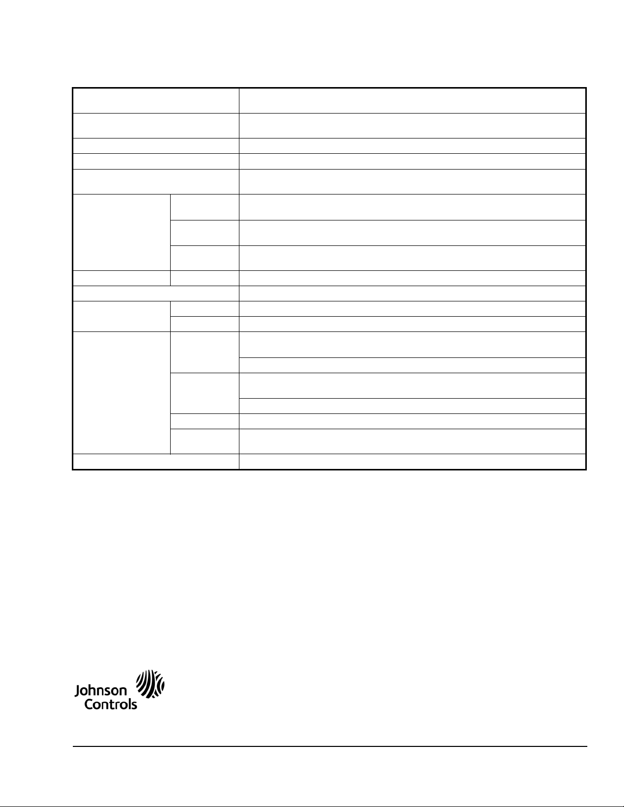
Technical Specifications
T600HCx-4 and T600HCx-4+PIR Series Thermostat Controllers
Power Requirements 19 to 30 VAC, 50/60 Hz, 2 VA (Terminals RC and C) at 24 VAC Nominal, Class 2 or
Safety Extra-Low Voltage (SELV)
Relay Contact Rating (Y1, G, W1,
and AUX)
Digital Inputs Voltage-Free Contacts across Terminal C to Terminals DI1 and DI2
Wire Size 18 AWG (1.0 mm Diameter) Maximum, 22 AWG (0.6 mm Diameter) Recommended
Temperature Sensor Type Local 10k ohm Johnson Controls Type II Negative Temperature Coefficient (NTC)
Temperature Range Backlit
Display
Heating
Control
Cooling
Control
Accuracy Temperature ±0.9F°/±0.5C° at 70.0°F/21.0°C Typical Calibrated
Minimum Deadband 2F°/1C° between Heating and Cooling
Ambient Conditions Operating 32 to 122°F (0 to 50°C); 95% RH Maximum, Noncondensing
Storage -22 to 122°F (-30 to 50°C); 95% RH Maximum, Noncondensing
Compliance United States UL Listed, File E27734, CCN XAPX,
Canada UL Listed, File E27734, CCN XAPX7,
Europe CE Mark, EMC Directive 2004/108/EC
Australia and
New Zealand
Shipping Weight 0.75 lb (0.34 kg)
30 VAC, 1.0 A Maximum, 3.0 A Inrush, Class 2 or SELV
Thermistor Sensor
-40.0°F/-40.0°C to 122.0°F/ 50.0°C in 0.5° Increments
40.0°F/4.5°C to 90.0°F/32.0°C
54.0°F/12.0°C to 100.0°F/38.0°C
Under UL 873, Temperature Indicating and Regulating Equipment
FCC Compliant to CFR 47, Part 15, Subpart B, Class A
Under CAN/CSA C22.2 No. 24, Temperature Indicating and Regulating Equipment
Industry Canada, ICES-003
C-Tick Mark, Australia/NZ Emissions Compliant
The performance specifications are nominal and conform to acceptable industry standards. For application at conditions beyond these
specifications, consult the local Johnson Controls office. Johnson Controls, Inc. shall not be liable for damages resulting from misapplication or
misuse of its products.
T600HCx-4 and T600HCx-4+PIR Series Single-Stage Thermostat Controllers Installation Instructions 19
Published in U.S.A. www.johnsoncontrols.com
 Loading...