

Page 1

T500 Series Programmable Thermostats
T500 Series Thermostats provide an economical
control solution for single-stage, multi-stage, or heat
pump systems. Up to four event setpoints can be
selected, as well as heat, cool, automatic changeover,
and off modes.
Thermostats are available in the following types:
T500HCP-1 (1 heat/1 cool), T500HPP-1 (heat pump,
3 heat/2 cool), T500HPP-2 (heat pump, 1 heat/1 cool),
T500MSP-1 (2 heat/2 cool). Each thermostat is
packaged with the necessary mounting hardware, and
installation is simple and fast for reduced cost.
FANs 216, 1628.3
Product/Technical Bulletin T500
Issue Date 0899
Features and Benefits
!!!! Low-Profile Design
!!!! No Batteries Required
!!!! Lockable Access Cover and
Keypad Lockout
!!!! Full Function Liquid Crystal
Display (LCD)
!!!! Remote Sensor Terminals
!!!! Auxiliary Output
!!!! Fuzzy Logic Control
!!!! Smart Fan Option
Figure 1: T500 Series Programmable Thermostats
Complements any decor
Retains scheduled events and temperatures
upon loss of power
Prevents unauthorized changes
Makes controls easy to read, easy to use
Allows the T500 thermostat to be mounted up
to 300 m (1,000 ft) away from the controlled
space using a SEN-500-1 (sold separately)
Energizes for auxiliary equipment operation
Optimizes control performance
Provides continous fan operation in the
occupied mode and intermittent operation at
night
© 1999 Johnson Controls, Inc.
Part No. 24-8347-35, Rev. E www.johnsoncontrols.com
Code No. LIT-216173
1
Page 2

ntroduction
I
ocation Considerations
L
The T500 thermostats use an adaptive control routine,
based on fuzzy logic, to determine the heating or
cooling load of the controlled space. The routine
calculates load by evaluating recent room conditions
and room reactions to heating and cooling. This load is
used to determine the cycle rate of the equipment,
giving optimal control of the space.
upplies Needed
S
•
drill
•
4.7 mm (3/16 in.) drill bit
•
3 mm (1/8 in.) flat-blade screwdriver
•
hammer
•
marking pencil
•
wire stripper
114. 3
(4-1/2)
Locate T500 thermostat as follows:
•
on a partitioning interior wall, and approximately
1.5 m (5 ft) above the floor in a location of average
temperature
•
away from direct sunlight or radiant heat, outside
walls or behind doors, air discharge grills,
stairwells, or outside doors
•
away from steam or water pipes, warm air stacks,
unheated/uncooled areas, or sources of electrical
interference
!
CAUTION:
nstallation and Wiring
I
Note: When replacing an existing thermostat,
remove and use wire tags to identify terminal
designations.
To install and wire the thermostat:
Shock Hazard.
Disconnect power supply before
wiring connections are made to
prevent electrical shock or
possible damage to the
equipment.
T500MSP-1
T500HPP-1
T500HCP-1
T500HPP-2
Figure 2: T500 Dimensions, mm (in.)
127
(5)
101.6
(4)
Dimn
22.2
(7/8)
1. Lift the thermostat cover and insert a small coin
into the slot located in the bottom center of the
thermostat case and twist 1/4 turn. (See Figure 3.)
Grasp the base from the bottom two corners and
separate from the thermostat.
2. Swing the thermostat out from the bottom, and lift
up and out of the base. Place the rectangular
opening in the base over the equipment control
wires protruding from the wall and, using the base
as a template, mark the location of the two
mounting holes. No leveling is required.
3. Use the supplied anchors and screws for mounting
on drywall or plaster. Drill two 4.7 mm (3/16 in.)
holes at the marked locations, tap nylon anchors
flush to wall surface, and fasten. (See Figure 4.)
4. Connect the wires from the existing system to the
thermostat terminals according to wiring
designations in Table 2, Table 3, Table 4, or
Table 5. Push extra wire back into the wall. Wires
must be flush to the plastic base. Plug hole with a
fireproof material to prevent drafts from affecting
ambient temperature readings.
2
T500 Series Programmable Thermostats Product/Technical Bulletin
Page 3

!
CAUTION:
Equipment Damage Hazard.
Before applying power, make all
wiring connections and check
the connections. Short-circuited
or improperly connected wires
may result in permanent
damage to the unit.
Figure 4: Mounting the Base
Figure 3: Separating the T500 from the Base
T500 Series Programmable Thermostats Product/Technical Bulletin
3
Page 4

nstalling the Thermostat Cover Lock
I
If desired, insert the plastic lock piece into the bottom
of the mounted base. The ends of the lock piece
should fit snugly under the lock pins extending from the
bottom of the mounted base. The tab in the middle of
the lock piece should extend downward from the
mounted base. (See Figure 5.)
To release the locking mechanism, press the lock
piece up and into the base while gently prying open the
thermostat at the same time. Use caution to avoid
cracking the thermostat base or cover.
eattaching the Thermostat and Cover
R
to the Installed Base
1. Position the thermostat inside the cover, and
attach on the hinged tabs located at the top of the
base.
2. Swing the thermostat and cover down, and press
on the bottom center edge until they snap in place.
(See Figure 6.)
Plastic Lock Pin
Snap
plastic lock
into place.
Figure 5: Installing the Thermostat Lock
Thermostat
Base
Hinged
Ta b s
Figure 6: Installing the T500 Thermostat
4
T500 Series Programmable Thermostats Product/Technical Bulletin
Page 5

IP Switch Selections
D
!
CAUTION:
Equipment Damage Hazard.
Before selecting a minimum
on/off time, ensure the
equipment can tolerate the
following maximum hourly
cycle rates: 7.5 cycles per hour
when using 4-minute on/off, or
15 cycles per hour when using
2-minute on/off.
Table 1: DIP Switch Selections
DIP Switch Switch
Selection
1
2
(Smart Fan)
3
4
5
Continued on next page . . .
On Allows 2-event (day, night) programming.
Off Allows 4-event (morning, day, evening, night) programming.
On During the
Off Allows the fan to cycle with equipment or run continuously if the
On Allows 2-minute minimum on/off time for heating and cooling equipment.
Off Allows 4-minute minimum on/off time for heating and cooling equipment.
On Locks the keyboard, disabling buttons to prevent tampering. (Only the
Off Unlocks the keyboard.
On
Off
Description
equipment or runs continuously if the
Fan
after programming the thermostat. Smart Fan remembers that the fan should run
continuously during these events after that.
During the
Pressing the
continuously for that night only.
At the end of the
cycling or continuous fan) for the
pressed, regardless of the event. Changing between events does not affect the fan.
∨∨∨∨ and ∧∧∧∧ buttons will function. See
Programming Changes While the Keyboard is Locked,
[Keyboard Locked]
T500HCP-1, T500HPP-2, T500MSP-1 only:
switch.
T500HPP-1 only:
the auxiliary heat is on. The compressor will remain off for 2 minutes after the
auxiliary heat is turned off to ensure that the heat pump coil has cooled.
T500HCP-1, T500HPP-2, T500MSP-1 only:
call for heat.
T500HPP-1 only:
heat to be on simultaneously.
morning, day, and evening
button need only be pressed once during the morning, day, or evening event
night
event, the fan automatically cycles with the equipment by default.
Fan
button during the night event overrides and causes the fan to run
night
event, Smart Fan remembers the fan selection (automatic
in this bulletin.)
Compressor/Auxiliary Interlocked: Turns off the compressor when
Compressor/Auxiliary Normal: Allows the compressor and auxiliary
events, the fan automatically cycles with the
Fan
button is pressed. To run continuously, the
morning, day, and evening
Programming the Thermostat, Making
Allows the fan to delay with the plenum
Allows fan to operate immediately with a
events and reverts back.
Fan
button is
Outdoor
Temporary [1 Hour]
and
and
T500 Series Programmable Thermostats Product/Technical Bulletin
5
Page 6

DIP Switch
(Cont.)
Switch
Selection
Description
6
On
Off
7
LED 1 icon
T500HPP-1, T500MSP-1 only:
T500HPP-1, T500MSP-1 only:
T500HPP-1, T500MSP-1 only:
off/on
(See Table 5.)
8
LED 2 icon
T500HPP-1, T500MSP-1 only:
off/on
(See Table 5.)
4 Events Per Day
Smart Fan Disabled
Heat/Cool: 4 Min ute
(Minimum On)
Keyboard Unlocked
Fan Immediate
with Heat Call
1
2
3
4
5
O
N
2 Events Per Day
Smart Fan Enabled
Heat/Cool: 2 Minute
(Min imum On)
Keyboard Locked
Fan On with
Plenum Switch
Figure 7: T500HCP-1 Factory-Set DIP Switch
Settings (All Off)
Allows multi-stage heating or cooling.
Allows single-stage heating or cooling.
Optional selection: LCD icon comes on with LED 1.
Optional selection: LCD icon comes on with LED 2.
Table 2: T500HCP-1 Output Terminal
Designations
Terminal Function
W1
Y1
G
R
24V
24V(c)
RS2
RS1
RS+V
Energizes on call for heating
Energizes on call for cooling
Energizes fan on call for heating or
cooling or by pressing
Fan
button
Independent switching voltage
24 VAC from equipment transformer
24 VAC (common) from equipment
transformer
Connections for outdoor air
temperature or indoor remote
sensors; refer to instructions included
with sensors.
W1
Y1
24V
24V(c)
RS2
RS1
RS+V
Heating
Cooling
Fan
Common
Figure 8: T500HCP-1 Wiring Terminals
6
T500 Series Programmable Thermostats Product/Technical Bulletin
G
R
Hcp-1wire
Page 7

4 Events Per Day
Smart Fan Disabled
Heat/Cool: 4 Minute
(Minimum On)
Keyboard Unlocked
Compressor/Auxiliary
Normal
Single Stage
LED 1 Icon Off
LED 2 Icon Off
1
2
3
4
5
6
7
8
ON
Figure 9: T500HPP-1 DIP Factory-Set
DIP Switch Settings
1st Stage Compressor
24VAC
Figure 10: T500HPP-1 Wiring Terminals
2 Events Per Day
Smart Fan Enabled
Heat/Cool: 2 Minute
(Minimum On)
Keyboard Locked
Compressor/Auxiliary
Interlocked
Multi-stage
LED 1 Icon
(Filter)
LED 2 Icon
(Wrench/Fault)
W2
Table 3: T500HPP-1 Output Terminal
Designations
Terminal Function
W2
Y2
W1
Y1
G
R
24V
24V(c)
O
B
LED 1
LED 2
RS2
RS1
RS+V
NO
COM
NC
Energizes auxiliary heat as
second-stage heating in emergency
heat mode
Energizes compressor No. 2 on call
for second-stage heating or cooling
Energizes auxiliary heat as
last-stage heating or first-stage in
emergency heat
Energizes compressor No. 1 on call
for heating or cooling
Energizes fan on call for heating or
cooling or by pressing
Fan
button
Independent switching voltage
24 VAC from equipment transformer
24 VAC (common) from equipment
transformer
Energizes reversing valve in the
cooling mode
Energizes reversing valve in the
heating mode
Input connection that energizes
LED 1 or LED 2 from remote status
device (See Figure 9 and Table 6.)
Connections for outdoor air
temperature or indoor remote
sensors; refer to instructions
included with sensors.
The relay coil is de-energized in the
night event. In all other events, the
relay coil is energized. (See
Figure 16.)
T500 Series Programmable Thermostats Product/Technical Bulletin
7
Page 8

4 Events Per Day
Smart Fan Disabled
Heat/Cool: 4 Minute
(Minimum On)
Keyboard Unlocked
Fan Immediate
with Heat Call
1
2
3
4
5
ON
2 Events Per Day
Smart Fan Enabled
Heat/Cool: 2 Minute
(Minimum On)
Keyboard Locked
Fan On with
Plenum Switch
Table 4: T500HPP-2 Output Terminal
Designations
Terminal Function
Single-Stage
Heat Pump
Thermostat
Conventional
Single-Stage
Heat/Cool
Thermostat
Figure 11: T500HPP-2 Factory-Set DIP Switch
Settings (All Off)
RS2
RS1
RS+V
Compressor
Fan
24VAC
Common
W1
B
Hpp-2wire
Figure 12: T500HPP-2 Wiring Terminals
Note:
W1*
Jumpered to Y1
(See Note.)
Energizes on call
for heating
(See Note.)
Y1
Energizes
compressor
contactor
Energizes on call
for cooling
(See Note.)
(See Note.)
G
R
Energizes fan on call for heating or
cooling or by pressing
Fan
button
Independent switching voltage
(See Note.)
24V
24V(c)
24 VAC from equipment transformer
24 VAC (common) from equipment
transformer
RS2
RS1
RS+V
O
Connections for outdoor air temperature
or indoor remote sensors; refer to
instructions included with sensors
Energizes
Not used
reversing valve in
the cooling mode
B
Energizes
Not used
reversing valve in
the heating mode
Single-Stage Heat Pump:
Leave the factory-installed jumper connected
between W1 and Y1 and wire O or B as shown in
Figure 12.
Conventional Single-Stage Heat/Cool:
Remove the factory-installed jumper between W1
and Y1 and wire as shown in Figure 12. Note that
the O and B terminals are not used in this
application.
8
T500 Series Programmable Thermostats Product/Technical Bulletin
Page 9

4 Events Per Day
Smart Fan Disabled
Heat/Cool: 4 Minute
(Minimum On)
Keyboard Unlocked
Fan Immediate
with Heat Call
Single Stage
LED 1 Icon Off
LED 2 Icon Off
1
2
3
4
5
6
7
8
ON
2 Events Per Day
Smart Fan Enabled
Heat/Cool: 2 Minute
(Minimum On)
Keyboard Locked
Fan On with
Plenum Switch
Multi-stage
LED 1 Icon
(Filter)
LED 2 Icon
(Wrench/Fault)
Figure 13: T500MSP-1 Factory Set
DIP Switch Settings
2nd Stage Heating
2nd Stage Cooling
1st Stage Heating
1st Stage Cooling
NO
COM
NC
Fan
24VAC
Common
W2
Figure 14: T500MSP-1 Wiring Terminals
Table 5: T500MSP-1 Output Terminal
Designations
Terminal Function
R
W2
Y2
W1
Y1
G
R
24V
24V(c)
O
B
LED 1
LED 2
RS2
RS1
RS+V
NO
COM
NC
Energizes on a call for
second-stage heat
Energizes on a call for
second-stage cooling
Energizes on a call for first-stage
heat
Energizes on a call for first stage
cooling
Energizes fan on call for heating or
cooling or by pressing the
Fan
button
Independent switching voltage
24 VAC from equipment
transformer
24 VAC (common) from equipment
transformer
Energizes in the cooling mode
Energizes in the heating mode
Input connection that energizes
LED 1 or LED 2 from remote status
device (See Figure 13 and
Table 6.)
Connections for outdoor air
temperature or indoor remote
sensors; refer to instructions
included with sensors
The relay coil is de-energized in the
night event. In all other events, the
relay coil is energized. (See
Figure 18.)
T500 Series Programmable Thermostats Product/Technical Bulletin
9
Page 10

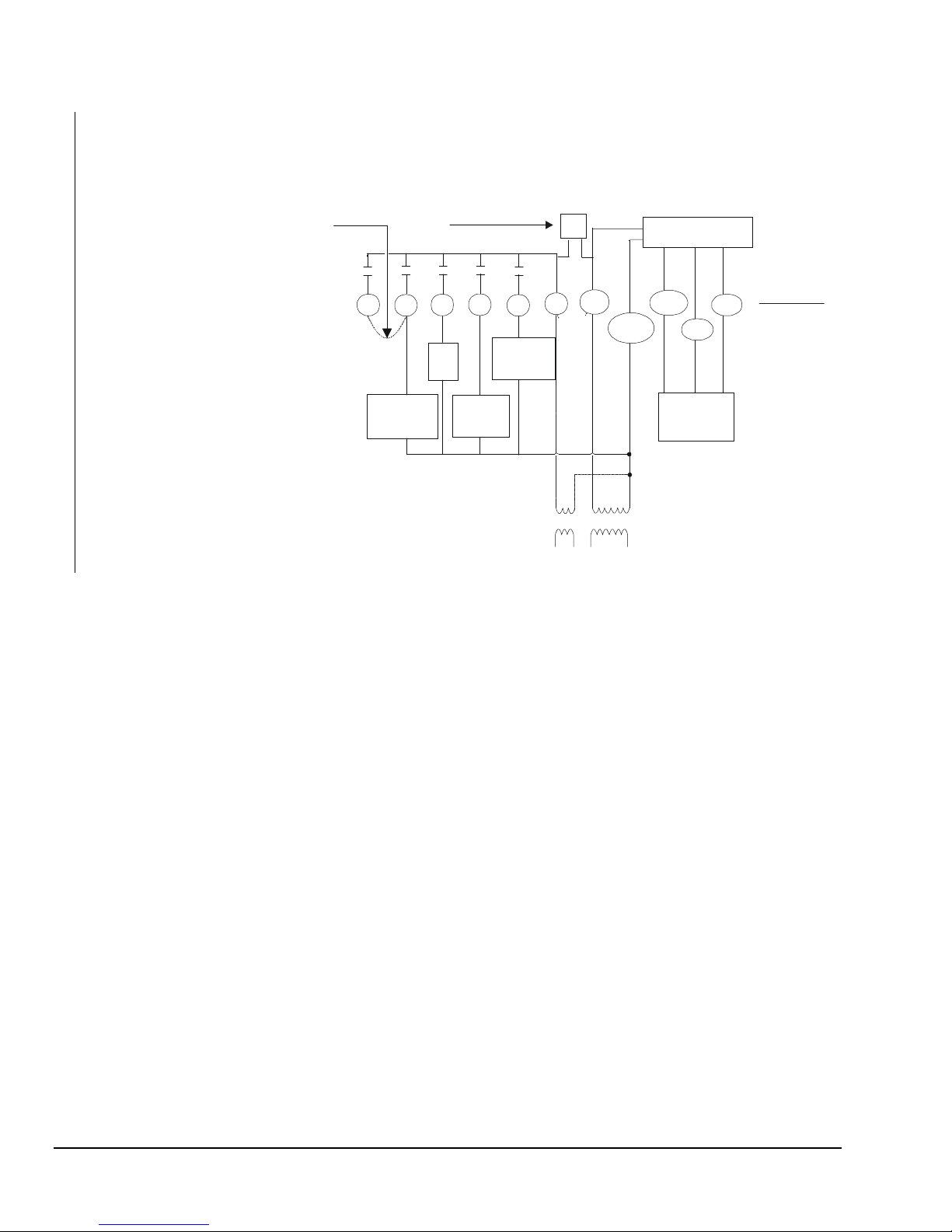
iring Diagrams
W
If the transformer (T2) is to power all of the loads,
R and 24 must be connected by inserting jumper J 1
located above the relays. If a separate 24V
transformer (T1) is to be used, remove J 1 to
disconnect R and 24V(c).
P
P
J1P
Electronics
W1
1st Stage
Heat
Compressor
24V
Y1 G
Fan
1st Stage
Optional
R
T1
T2
24V(c)
RS+V
Figure 15: T500HCP-1 Wiring Schematic
RS1
Remote
Sensor
(if used)
RS2
Thermostat
Equipment
Hcp-1diag
10
T500 Series Programmable Thermostats Product/Technical Bulletin
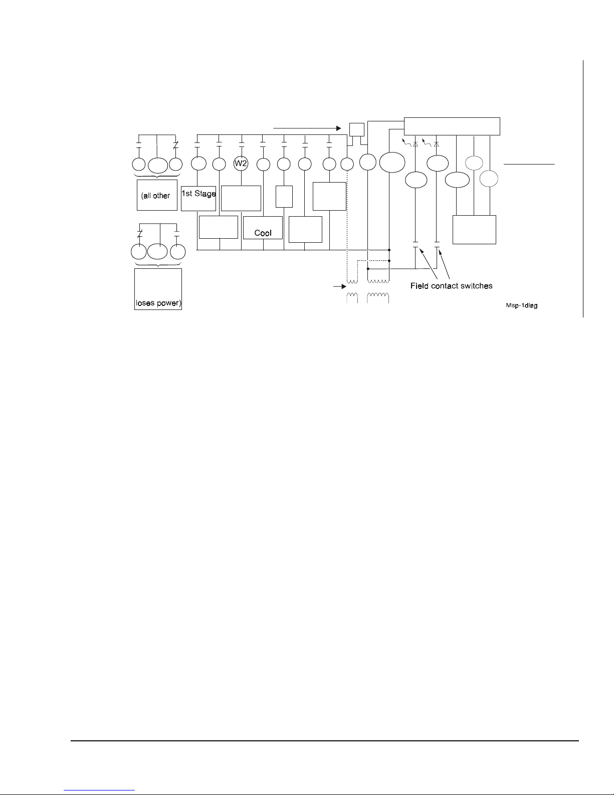
Page 11

If the transformer (T2) is to power all of the loads
R and 24V must be connected by inserting jumper
1, located above the relays. If a separate 24V
JP
transformer (T1) is to be used, remove the jumper
to disconnect R and 24V.
JP1
JP1
Electronics
COM
NO NC
OCC
(all other
events)
COM
NO
UNOCC
(night event
if
thermostat
loses power)
1st Stage
NC
W1
Heat
1st Stage
Compressor
Y1 Y2W2G
2nd Stage
Heat
2nd Stage
Compressor
Fan
Figure 16: T500HPP-1 Wiring Schematic
O
Reverse
Val ve
Cooling
Optional
B
Reverse
Val ve
Heating
24V(c)
24V
R
T1
T2
LED1
LED2
Field contact switches
RS+V
RS1
Remote
sensor
(if used)
RS2
Thermostat
Equipment
Hpp-1diag
T500 Series Programmable Thermostats Product/Technical Bulletin
11
Page 12
Single-Stage Heat Pump:
Leave the factory-installed jumper
connected between W1 and Y1 and
wire O or B as shown.
Conventional Single-Stage Heat/Cool:
Remove the factory-installed jumper
between W1 and Y1 and wire as shown
in Figure 12. Note that the O and B terminals
are not used in this application.
If the transformer (T2) is to power all of the
loads, R and 24V must be connected by
inserting jumper JP1, located above the
relays. If a separate 24V transformer (T1)
is to be used, remove the jumper JP1 to
disconnect R and 24V(c).
W1
Y1
G
Fan
O B
Reverse
Val ve
Heating
JP1
24V
R
24V(c)
Electronics
RS+V
RS1
RS2
Thermostat
Equipment
Reverse
Compressor
Val ve
Cooling
T1 T2
Figure 17: T500HPP-2 Wiring Schematic
Remote
sensor
(if used)
Hpp2-diag
12
T500 Series Programmable Thermostats Product/Technical Bulletin
Page 13
If the transformer (T2) is to power all of the loads,
R and 24V must be connected by inserting jumper
J 1 located above the relays. If a separate 24V
P
transformer (T1) is to be used, remove the jumper
1 to disconnect R and 24V(c).
JP
JP1
Electronics
NO NC
COM
OCC
events)
COM
UNOCC
or
if
NC
NO
(night event
thermostat
W1
Heat
1st Stage
Y1
2nd Stage
Cool
24V(c)
24V
R
T2
T1
Heat
2nd Stage
Y2
G
Fan
Reverse
Val ve
Cooling
OB
Reverse
Val ve
Heating
optional
Figure 18: T500MSP-1 Wiring Schematic
LED2
LED1
RS+V
Remote
(if used)
RS1
Sensor
Thermostat
Equipment
RS2
T500 Series Programmable Thermostats Product/Technical Bulletin
13
Page 14

ommissioning
C
The thermostat normally displays room temperature
and mode of operation (whether cooling
or heating
is currently on).
Table 6: LED Indicators (T500MSP-1, T500HPP-1 only)
LED Position Function
Left
Center
Right
hermostat Operation Overview
T
Used to set current day and time.
Used to select event start times.
Used for constant hold.
An external switch on the LED 1 Display enables the filter symbol; see Table 1
(T500HPP-1 only) Indicates when highest stage heat is activated; internally controlled
An external switch on the LED 1 Display enables the wrench symbol; see Table 1
Used to select setpoints.
setpoint
Clock
Set Temp
Program
66
Mo
12:51
LEDs (T500MSP-1, T500HPP-1 only) indicate
system activity or problems. See Table 6.
Outdoor
Mode
AM
Fan
ResumeHold
Used to display outdoor temperature
(optional).
Used to select mode of operation.
Used to run fan continuously.
Used to resume normal operati on.
14
T500 Series Programmable Thermostats Product/Technical Bulletin
Piface1
Figure 19: T500 Pushbuttons
Page 15

Mode
Repeated pressing of the
selection from four modes of operation (five for the
T500HPP-1/Heat Pump model):
•
When the
displayed, the thermostat is in the cooling mode.
When the thermostat is calling for cooling, the
snowflake will flash.
•
When the
displayed, the thermostat is in the heating mode.
When the thermostat is calling for heating, the
flame will flash.
•
When the
are displayed, the thermostat will control using the
emergency heat with the compressor locked out.
(T500HPP-1/Heat Pump only.)
•
When the
and word
automatically change over between heating and
cooling.
Note: The thermostat never allows less than a 1°C
•
When
operate.
Note: Use caution when using the
Snowflake
Flame
Flame
Snowflake
AUTO
(2°F) difference between the heating and
cooling setpoints.
OFF
is displayed, the equipment will not
extremely cold weather.
Mode
button allows
and the word
and the word
and
E Ht
(emergency heat)
and the
are displayed, the thermostat will
COOL
HEAT
are
Flame
OFF
mode in
are
symbols
T500 does not bring on the next stage of cooling or
heating if it knows that the system can change the
temperature by 6 degrees in 1 hour, or 1 degree in
10 minutes. To verify thermostat operation, force the
next stage on by changing the setpoint more than
2 degrees.
an
F
If continuous fan is not selected, the fan will operate
automatically and the fan symbol will be off. To select
continuous fan operation, press the Fan button. The
fan symbol
Smart Fan DIP switch in Table 1.
Clock
will be displayed. (See Figure 20.) See
Outdoor
66
Set Temp
Program
Hold
Mo
4:22
AM
Mode
Fan
Resume
Press to
select
continuous
fan
op erat ion .
Celsius/Fahrenheit
∨∨∨∨
Press the
between Celsius and Fahrenheit display.
uzzy Logic Control
F
Over time, the T500 learns how long it takes the
system to meet the load. If the system can change the
room temperature quickly, the T500 allows the
thermostat to drift further from setpoint before starting
the equipment. If the system takes a longer period of
time to change the room temperature, it will not allow
the temperature to drift as far from setpoint. The T500
also takes into account the minimum On/Off times.
The 2-minute On/Off time allows the equipment to
cycle more frequently at smaller differentials than the
4-minute On/Off time. For multi-stage applications, the
∧∧∧∧
and
buttons simultaneously to alternate
T500 Series Programmable Thermostats Product/Technical Bulletin
Figure 20: Selecting Continuous Fan Operation
Outdoor Button
When an outdoor temperature sensor (order
separately) is connected to the T500 thermostat, you
can display the current outdoor temperature by
pressing the
not connected, the thermostat will display “— —”.
See the
Outdoor
Ordering Information
button. If the sensor option is
section.
15
Page 16

rogramming Overview
P
Thermostat programming is a 3-part process: setting
current time, choosing event setpoints, and setting
event times. Throughout the programming procedure,
the following terms will be used:
Event
= morning, day, evening, night
Event time
Event setpoint
= the time the event starts
= the temperature setpoint of the
event; each event can have only one setpoint for
heating or cooling.
Table 7: Sample 4-Event Program Settings
Event Morning Day Evening Night
Event
Setpoint
Monday
Tuesday
Heat
68°F
Cool
80°F
Heat
72°F
(Time) (Time) (Time) (Time)
6 a.m. 8 a.m. 5 p.m. 11 p.m.
6 a.m. 8 a.m. 5 p.m. 11 p.m.
Program flexibility is achieved by varying the program
start times. When consecutive events are programmed
with the same event time, the thermostat will control
the temperature according to the setpoint of the latest
event.
Table 7 is an example of event times and setpoints for
a given week using a 4-event program. See the
owner’s manual for a blank table.
Note: A 2-event program will only include day
and night events.
Cool
76°F
Heat
66°F
Cool
78°F
Heat
60°F
Cool
85°F
Wednesday
Thursday
Friday
Saturday
Sunday
* Thermostat controls to the day setpoint until noon.
** Thermostat controls to the night setpoint until 6 a.m. Monday morning.
6 a.m. 8 a.m. 5 p.m. 11 p.m.
6 a.m. 8 a.m. 5 p.m. 11 p.m.
6 a.m. 8 a.m. 5 p.m. 11 p.m.
6 a.m.* 6 a.m. 12 p.m. 12 p.m.
12 p.m. 12 p.m. 12 p.m. 12 p.m.**
16
T500 Series Programmable Thermostats Product/Technical Bulletin
Page 17

rogramming the Thermostat
P
Setting the Current Day and Time
To set the current day and time:
1. Press and release the
Clock
button.
The display will flash a day of the week.
2. Press the
∨∨∨∨ or ∧∧∧∧
buttons until the current day
shows.
3. Press
4. Press the
Clock
again. The display will flash the hour.
∨∨∨∨ or ∧∧∧∧
buttons until the current hour
shows. Be sure AM or PM corresponds to the
proper time.
5. Press
Clock
again. The display will flash minutes
(:00). (See Figure 21.)
6. Press the
∨∨∨∨ or ∧∧∧∧
buttons until the current minutes
show.
7. Press
Clock
to complete the procedure or wait
15 seconds to return to normal display.
Setting the Event Setpoints
Setpoints are programmed for both heating and
cooling
four (morning, day, evening, and night) events per day.
(See Table 1.) To program a setpoint:
modes, and either two (day and night) or
6. Select the desired mode of operation: heat, cool,
auto.
7. When programming is complete, press the
Resume
!
button to return to the normal display.
CAUTION:
Equipment Damage Hazard.
Operating a cooling system
without proper limit controls in
very low outdoor air
temperatures can permanently
damage the cooling equipment.
Press to
set days,
hours, and
minutes.
Clock
Set Temp
Program
Mo
66
AM
Outdoor
Mode
Fan
:0 0
Hold
Resume
1. Press the
2. Press the
cool
), event (morning, day, evening, or night)
Mode
button until heat
Set Temp
button. The mode (heat
is displayed.
symbols, and the present setpoint will be
displayed.
3. Press the
∨∨∨∨ or ∧∧∧∧
buttons to adjust setpoints for the
displayed event and mode.
the
Set Temp
∨∨∨∨ or ∧∧∧∧
to move to the next event. Press
buttons to adjust the setpoint. Repeat
4. Press
this step until all event setpoints are programmed.
5. Press
Mode
until cooling
is displayed, and
repeat Steps 2 through 4.
or
Figure 21: Setting the Current Day and Time
Push Button Auto Repeat
Holding the
through the programming menu in sequence to the
desired option.
Program
button down will advance you
T500 Series Programmable Thermostats Product/Technical Bulletin
17
Page 18

Setting the Event Times
To program event times:
1. Press and release the
Program
button. The
morning event symbol and the current day
appear.
2. Press the
∨∨∨∨ or ∧∧∧∧
buttons to select the first single
day or the first day of a block of days to be
programmed.
3. Press and release
Program
. Press the
∨∨∨∨ or ∧∧∧∧
buttons to set the start time hour for the first event.
4. Press and release
Program
. Press the
∨∨∨∨ or ∧∧∧∧
buttons to set the minutes in 10-minute intervals
(i.e., 8:10, 8:20, etc.).
5. Press
Program
to advance to the next event.
6. Repeat Steps 3 through 5 for all remaining events.
After programming the last event, press
Copy
will be displayed.
Program
7. If you do not want to copy the program, press
Program
program, press the
individual days to copy the program to. The
and proceed to Step 9. To copy the
∨∨∨∨ or ∧∧∧∧
buttons to select
Copy
function will only allow program times to be copied
to sequential days (i.e., Tuesday, Wednesday,
Thursday).
8. Press
Program
to copy program settings to the
selected days of the week.
9. Repeat the procedures for
Setting the Event Times
for any remaining unprogrammed days of the
week.
10. When finished, verify that all events are
programmed correctly by repeatedly pressing the
Program
Program
button. When
to skip to the next day.
11. When programming is complete, press
Copy
appears, press
Resume
to
return to normal display.
Clock
Outdoor
66
Set Temp
Press to
Program
set hours,
minutes,
and
events .
Mo
5:00
AM
Figure 22: Setting the Event Times
.
Scheduling 1-, 2-, 3- and 4-Event Days in
the Same Week
If the DIP switch is set for 4-event days, a 2-event day
can be programmed by setting the same event time for
consecutive events. See the example shown in
Table 7.
Making Programming Changes While the
Keyboard is Locked
To make programming changes while the DIP switch is
set to lock the keyboard:
1. Open the thermostat and switch the DIP switch to
unlock the keyboard. (See
Selections.
) Close the thermostat.
2. Make necessary program changes.
3. Open the thermostat and switch the DIP switch to
lock the keyboard again. Close the thermostat.
Table 1: DIP Switch
Mode
Fan
ResumeHold
Note: See Table 7 for an example of programming
for a given week.
18
T500 Series Programmable Thermostats Product/Technical Bulletin
Page 19

O
verride
Constant Hold
To maintain a constant temperature setting:
1. Press the
Mode
button until the desired mode is
displayed (heating, cooling, auto).
∨∨∨∨
2. Press the
∧∧∧∧
or
buttons to set the desired
setpoint(s).
Note: If the Auto mode is used, press
and press the
cooling setpoint. Press
∨∨∨∨ or ∧∧∧∧
buttons to select a heating setpoint.
Mode
Press
∨∨∨∨ or ∧∧∧∧
buttons to select a
Mode
again to set the mode back to
Mode
again, and the
Auto.
3. Press the
Hold
button. Setpoint(s) will be
maintained continuously.
4. Pressing and releasing the
cancel the
Hold
and return to programmed
Resume
button will
setpoints.
Clock
Outdoor
66
Set Temp
Mode
twice,
Temporary (3 Hour) (Keyboard
Unlocked)
To implement a temporary change from the current
event setpoint for a 3-hour period:
1. Press the
∨∨∨∨ or ∧∧∧∧
buttons to change the scheduled
setpoint ± 3°C or ± 6°F. The current mode of
operation will appear on the display and an
hourglass symbol
will appear. The temporary
setpoint will be maintained for 3 hours.
Note: If the Auto mode is used, press
press the
setpoint. Press
∨∨∨∨ or ∧∧∧∧
buttons to select a heating
Mode
again, and the
Mode
, and
∨∨∨∨
or
∧∧∧∧
buttons to select a cooling setpoint.
2. Pressing and releasing the
Resume
button will
cancel the override and return to the programmed
setpoint at any time during the 3 hours.
Note: If the setpoint is altered while in the night
mode, the thermostat will change to the day
mode setting.
Temporary (1 Hour) (Keyboard Locked)
To implement a temporary change from the current
event setpoint for a 1-hour period:
Program
Mo
AM
Fan
HOLD
ResumeHold
Press for
constant
hold.
Figure 23: Constant Override (Hold)
Progressive Recovery
During the night mode the thermostat is designed to
anticipate a programmed setpoint change. With
Progressive Recovery, the desired temperature will be
attained at the programmed time instead of beginning
the temperature cycle change. Recovery option is
selected by pressing the
simultaneously.
Program
and
Fan
buttons
1. Press the
∨∨∨∨ or ∧∧∧∧
buttons to change the scheduled
setpoint. The current mode of operation will appear
on the display and an hourglass symbol
appear. The temporary setpoint will be maintained
for 1 hour.
Note: If the Auto mode is used, press
press the
setpoint. Press
∨∨∨∨ or ∧∧∧∧
buttons to select a heating
Mode
again, and the
Mode
buttons to select a cooling setpoint.
2. Pressing and releasing the
Resume
button will
cancel the override and return to the programmed
setpoint at any time during the 1 hour.
will
, and
∨∨∨∨ or ∧∧∧∧
T500 Series Programmable Thermostats Product/Technical Bulletin
19
Page 20

etting Electronic Outdoor High and
S
Low Temperature Balance Points
(T500HPP-1 only)
The optional outdoor temperature sensor (order
separately) can be installed to allow the selection of
outdoor balance points that will lock out auxiliary heat
or cooling, depending on the outdoor temperature.
The factory-set HibP (auxiliary heat) and LobP
(compressors) setpoints are 48°C (118.4°F), and
-48°C (-54.4°F) respectively. The HibP and/or LobP will
be shown on lower LCD.
The HibP is the temperature above which the auxiliary
heat is locked out. The LobP is the temperature below
which the compressors are locked out.
12:00 AM will flash and the thermostat will control to
the night event setpoint until the clock is reset.
Note: If the power fails when the thermostat is in the
continuous HOLD mode, the thermostat will
continue controlling to the HOLD temperature
when power is restored. When the user
presses the
flash 12:00 AM and will remain in the night
event setpoint until the clock is reset.
erification
V
To verify proper functioning of the thermostat:
1. Press the
mode. (See Figure 24.)
Resume
Mode
button to select the heat or cool
button, the clock will
To set the balance points:
1. Press and hold the
Mode
the
2. Raise or lower the HibP (high balance point) by
pressing the
3. Set the LobP (low balance point) by pressing and
holding the
the display.
4. Raise or lower the LobP by pressing the
buttons to set the auxiliary heat setpoint.
5. Press
ptions
O
button.
Outdoor button. LobP
Resume
Outdoor
HibP
∨∨∨∨ or ∧∧∧∧
buttons.
to return to the normal display.
button while pressing
will appear on the display.
will appear on
∨∨∨∨ or ∧∧∧∧
Remote Sensor
The indoor remote sensor allows the T500 to be
mounted away from the controlled space, and allows
use of multiple sensors for temperature averaging.
Order separately. See
Table 10: Optional Accessories.
Clock
∨∨∨∨ or ∧∧∧∧
buttons to raise the setpoint
section.
Outdoor
2. Press the
above or below the current ambient temperature.
The thermostat should call for either heating or
cooling.
If the equipment does not come on, proceed to the
Troubleshooting
66
Set Temp
Program
Mo
AM
Mode
Fan
Press to
select mode
(heat or cool) .
5:00
ResumeHold
Figure 24: Verifying Proper Operation
Outdoor Sensor
Order separately. See
ower Failures
P
If power fails, AC will be displayed for 2 hours. After
2 hours, the display will go blank.
If power is restored in the first 2 hours, the internal
clock will be current and the thermostat will resume
normal operation. If power is restored after 2 hours,
20
T500 Series Programmable Thermostats Product/Technical Bulletin
Table 10: Optional Accessories.
Sensor Calibration (Fan/10 Seconds)
The internal and remote sensors can be calibrated to
eliminate wire resistance errors or to match another
reference.
1. Press and hold the
2. Adjust the temperature with the
The temperature is shown on the lower display to
the hundredths place. For example, 72°F on the
large display is shown as 72 13.
Fan
button for 10 seconds.
∨∨∨∨ or ∧∧∧∧
buttons.
Page 21

roubleshooting
T
Table 8: Troubleshooting
Symptom Possible Cause Corrective Action
No display/faint display ...
Keyboard inoperative ...
Thermostat will not call for
heat ...
Thermostat will not call for
cooling ...
Fan does not turn on ...
AC appears on the LCD ...
LCD shows missing or
extra segments ...
Supply voltage incorrect Use a voltmeter to check the voltage between the 24V and
24V(c) terminals. Voltage should be between 20-30 VAC.
If voltage is less than 20 VAC, disconnect the thermostat
and check the voltage between 24V and the other system
wires; see possible causes below. If voltage is greater than
30 VAC, troubleshoot the power source and replace the
thermostat.
System transformer weak or
overloaded
Thermostat damaged
because system voltage
was greater than 30 VAC
Keyboard locked Switch the keyboard DIP switch to the unlocked position.
Compressor delay still in
progress
Thermostat setpoint is
satisfied
Compressor delay still in
progress
Thermostat setpoint is
satisfied
Fan failure Place a jumper between terminals R and G. Fan should
20-30 VAC is absent from
24V and 24V(c)
LCD failure Replace the unit.
Check and/or replace with a suitable 24V transformer.
Replace with new thermostat and ensure new thermostat is
isolated from the system using suitable relays and a
transformer of the proper rating.
Wait - equipment short cycle protection in progress.
Raise the heating setpoint using the
Wait - equipment short cycle protection in progress.
Lower the cooling setpoint using the
come on. If it does not, troubleshoot the fan system. If fan
does come on, replace the thermostat.
Using a voltmeter, measure voltage between the 24V and
24V(c) terminals. If the reading is less than 20 VAC, check
system transformer. If the voltage is between 20-30 VAC,
replace the thermostat.
button.
∧∧∧∧
button.
∨∨∨∨
T500 Series Programmable Thermostats Product/Technical Bulletin
21
Page 22

rdering information
O
Table 9: Ordering Information
Item Product Code Number
Programmable Thermostat, Single-stage, 1 Heat, 1 Cool
Programmable Thermostat, Multi-stage, 2 Heat, 2 Cool
Programmable Thermostat, Heat Pump, 3 Heat, 2 Cool
Programmable Thermostat, Heat Pump, 1 Heat, 1 Cool
ccessories
A
T500HCP-1
T500MSP-1
T500HPP-1
T500HPP-2
Table 10: Optional Accessories (includes mounting hardware)
Item Product Code Number
Remote Indoor Temperature Sensor
Outdoor Air Temperature Communication Module with Outdoor Air Sensor
Outdoor Air Temperature Communication Module with Duct Mount Sensor
Conversion Module
Thermostat Wall Plate
eplacement and Repair Parts
R
SEN-500-1
SEN-500-2
SEN-500-3
ACC-500-1
ACC-500-2
The SEN-500 series of products allows for easy
replacement of the sensor. For a replacement sensor,
contact the nearest Johnson Controls branch office or
wholesale distributor and order using the information
Table 10: Optional Accessories, Table 11:
from
Replacement Parts,
Table 12: Repair Parts
and
.
Table 11: Replacement Parts
Item Product Code Number
Replacement Outdoor Air Temperature Communication Module
Replacement Outdoor Air Temperature Sensor (including mounting hardware)
Replacement Duct Mount Temperature Sensor (including mounting hardware)
SEN-500-603
SEN-500-604
SEN-500-605
Table 12: Repair Parts
Item Product Code Number
3 in. Sensor Probe (use with outdoor air sensor)
8 in. Sensor Probe (use with duct mount sensor)
SEN-500-601
SEN-500-602
22
T500 Series Programmable Thermostats Product/Technical Bulletin
Page 23

pecifications
S
Product
Power Requirements
Relay Contact Rating
Recommended Wire Size
Occupied/Unoccupied
Relay Contacts
(T500HPP-1 and
T500MSP-1 only)
Thermostat Measurement
Range
Outdoor Air Temperature
Indication Range
Control Range
Display Resolution
Minimum Deadband
F Conversion
°°°°C/°°°°
Ambient Operating
Conditions
Continued on next page . . .
T500HCP-1, T500MSP-1, T500HPP-1, T500HPP-2
20-30 VAC, 50/60 Hz, 24 VAC nominal
Maximum Inductive: 1 ampere with surges to 3 amperes, 24 VAC Class 2
Maximum Resistive: 1 ampere, 24 VDC (2000 VA Maximum for all outputs)
Minimum: 10 uA for 24 VAC circuit; 10 mA for 24 VDC circuit
18 gauge
Single-Pole/Double-Throw; The normally open contact is closed in the night event or if the
thermostat loses power. The normally closed contact is closed in all other events.
0 to 48°C (28 to 124°F)
-48 to 48°C (-50 to 124°F)
Heating: 5 to 30°C in 1° steps; 38 to 88°F in 1° steps
Cooling: 16 to 40
1C or 1F
(Between heating and cooling) 1°C
20°C = 68°F, each Celsius degree above or below 20°C = 2°F
0 to 55°C (32 to 131°F); 5 to 90% RH non-condensing
C in 1° steps; 60 to 108°F in 1° steps
°
2°F
or
T500 Series Programmable Thermostats Product/Technical Bulletin
23
Page 24

pecifications (Cont.)
S
Ambient Storage
Temperatures
Dimensions (H x W x D)
Shipping Weight
FCC Compliance
The performance specifications are nominal and conform to acceptable industry standards. For application at conditions beyond these
specifications, consult the local Johnson Controls office. Johnson Controls, Inc. shall not be liable for damages resulting from misapplication
or misuse of its products.
This device complies with Class A Part 15 of the FCC rules. It was also verified to Class B. Operation is subject to the following two
conditions:
(1) This device may not cause harmful interference.
(2) This device must accept any interference received, including interference that may cause undesired operation.
This Class A digital apparatus meets all of the requirements of the Canadian Interference-Causing Equipment Regulations. Cet appareil
numerique de la Classe A respecte toutes les exigences du Reglement sur le materiel brouilleur du Canada.
-34 to 55°C (-30 to 131°F)
114.3 x 101.6 x 22.2 mm (4 1/2 x 4 x 7/8 in.) (T500HCP-1, T500HPP-2)
114.3 x 127 x 22.2 mm (4 1/2 x 5 x 7/8 in.) (T500HPP-1, T500MSP-1)
0.171 kg (0.37 lb) (T500HCP-1, T500HPP-2)
0.204 kg (0.45 lb) (T500HPP-1, T500MSP-1)
This equipment has been tested and found to comply with the limits for a Class A digital
device and verified to Class B pursuant to Part 15 of FCC Rules. These limits are designed
to provide reasonable protection against harmful interference when this equipment is
operated in a commercial environment. This equipment generates, uses, and can radiate
radio frequency energy and, if not installed and used in accordance with the instruction
manual, may cause harmful interference to radio communications. Operation of this
equipment in a residential area is likely to cause harmful interference in which case the
user will be required to correct the interference at his/her own expense.
Controls Group
507 E. Michigan Street
P.O. Box 423 Printed in U.S.A.
Milwaukee, WI 53201 www.johnsoncontrols.com
24
T500 Series Programmable Thermostats Product/Technical Bulletin
 Loading...