

Page 1
Pneumatic Control Manual 717.1
Archived Document
Room Devices Section
T-4000 Series Room Thermostat
Adjusting Instructions*
Technical Bulletin T-4000
Issue Date 0984
The T-4000 Series Pneumatic
Room Thermostats are factory
calibrated to the values specified
in Table 1. If these settings are
suitable to the application, no
adjustments need to be made. If
different settings are required,
turn the set point dial to the
desired value.
If the room temperature is out of
control, determine the cause of
the problem. Possible causes
not involving the thermostat are
listed below.
1. Check for proper operation
of the controlled device.
*
This bulletin provides adequate instructions for making basic adjustments to
T-4000 series room thermostats. For more detailed information, contact the local
branch office.
2. Check to see if the controlled
medium (water, for example)
is hot or cold enough to
maintain the desired
temperature.
3. Check for unusual or
extreme loads in the space
which may overcome the
efforts of the thermostat to
maintain control.
If it is determined that the
thermostat is out of adjustment,
follow the appropriate instructions
to recalibrate the instrument.
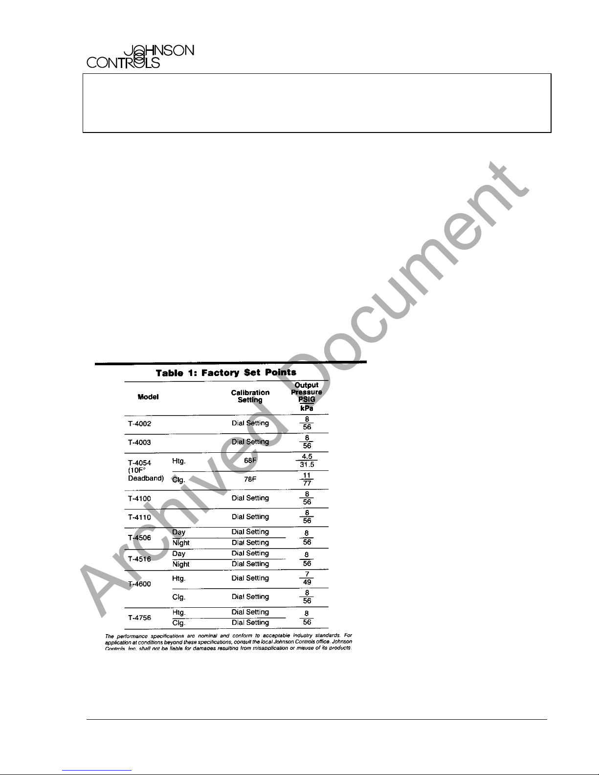
Sensitivity Adjustment
(See Fig. 1)
All T-4000 series thermostats
have an integral output pressure
test port. The newer high volume
output thermostats have a plug-in
test port fitting which accepts a
hypodermic needle test probe
and gage (X-200-140 and G2010-11). On older models, the
test port cap screw must be
removed to accept a screw-in
test gage (X-200-19). For these
units, a test port fitting (T-4000-
615) can be ordered. All low
volume output thermostats have
hypodermic needle test points.
For units that require a screw-in
gage, remember to replace the
test port cap screw after
adjustment.
The sensitivity of the T-4000
series instruments is factory set
at 2.5 PSI/F° (32 kPa/C°). It is
adjustable from 1 to 3 PSI/F
(13 to 38 kPa/C°) for low volume
output thermostats and from .
75 to 4 PSI/F° (10 to 51 kPa/C°)
for high volume output
thermostats. (Sensitivity of the T4003 is fixed at 2.5 PSI/F°).
1. Furnish the appropriate
supply pressure to the
instrument.
2. Insert the appropriate gage.
3. Note the output pressure.
Note:
The output pressure
for T-4054 thermostats must
be within one of the two
control ranges (not within the
deadband range).
4. For high volume output
thermostats, move the
sensitivity slider toward the
control port to increase or
away from the control port to
decrease the sensitivity. For
low volume output
thermostats, move the
sensitivity slider down to
°
© 1984 Johnson Controls, Inc.
Code No. LIT-7171089X
1
Page 2
increase or up to decrease
Archived Document
the sensitivity.
5. Check the output pressure.
If it is different from the value
found in step 3, turn the
sensitivity slider adjusting
screw until the output
pressure equals that value.
For low volume output
(plastic body) instruments,
use the output adjusting
screw to adjust the output
pressure.
6. Check the sensitivity.
Change the control setting
on the dial by at least 5F°
and note the new output
pressure. The change in
output pressure divided by
the change in dial setting is
the actual sensitivity.
7. Repeat steps 4 through 6
until the desired sensitivity is
obtained.
T-4003 Range of Remote
Readjustment
The range of remote
readjustment is adjustable from
.15 to 2.5 F°/PSI (.012 to
.2C°/kPa) and is factory set at
0.5 F°/PSI (.04 C°/kPa). To
determine if the range of remote
readjustment needs to be
adjusted, proceed as follows:
1. Insert the test gage into the
test port fitting and note the
output pressure.
2. Set the master pressure to
4 psig (28 kPa).
3. Turn the set point dial to 80F
and turn the calibration
screw to obtain a 3 psig
(21 kPa) output pressure.
4. Set the master pressure to
14 psig (98 kPa).
5. Turn the set point dial until
the output pressure returns
to 3 psig.
6. The change in dial setting
divided by the 10 psig
(70 kPa) change in master
pressure (14 psig - 4 psig =
10 psig) is the actual range
of readjustment. If this is not
the desired range, move the
range of readjustment slider
(sensitivity slider in Fig. 1a)
toward the control port to
decrease or away from the
control port to increase the
range of readjustment.
Readjust the slider screw to
the pressure noted in step 1
above. Repeat steps 2
through 6 until the desired
range is obtained.
Set Point Adjustment
Before calibrating the instrument,
check to see if the output
pressure is already at an
appropriate value according to
the ambient temperature. For
example, if the actual room
temperature is below the set
point and the output signal is
calling for more heat, the
thermostat is doing its job and
does not require adjustment.
T-4002 and T-4100 (See Fig. 1)
1. Insert the test gage.
2. Furnish supply air to the
instrument (restricted supply
for T-4100).
3. Note the ambient
temperature in the space.
4. Turn the set point dial to that
temperature.
5. Turn the calibration screw
until the output pressure is at
the mid spring range of the
controlled device.
6. Turn the set point dial to the
desired set point.
T-4003 Set Point Adjustment
Insert the gage and set the
master pressure to one half of
the supply pressure. Follow
steps 3 through 6 under T-4002
Set Point Adjustment.
2 T-4000 Technical Bulletin
Page 3
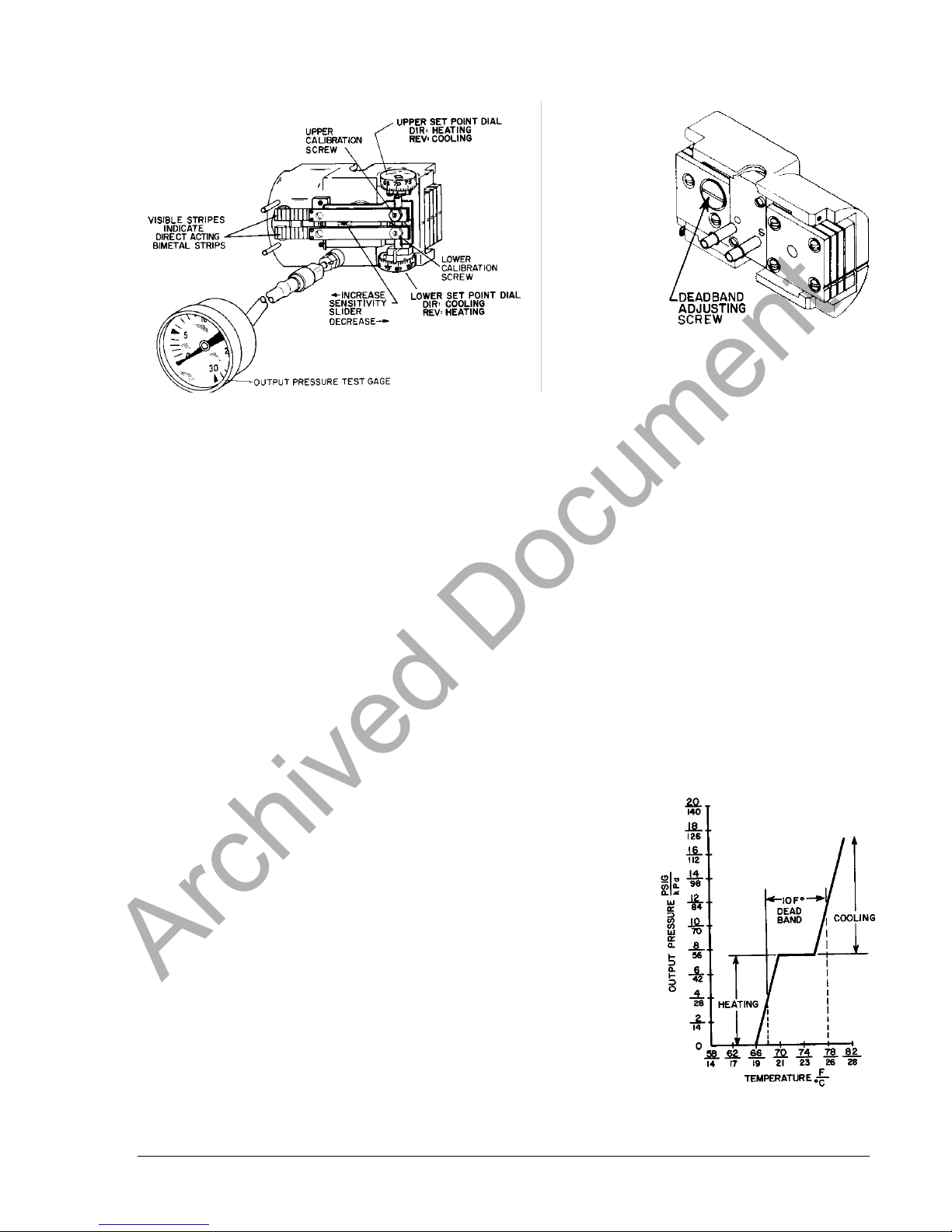
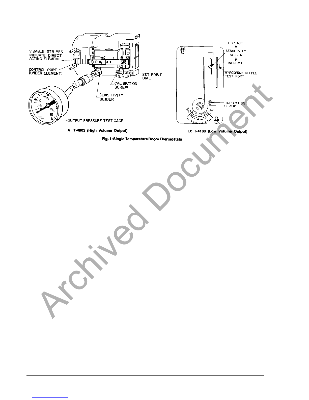
Fig. 2: T-4054 Adjustments
Archived Document
Fig. 3: Back View of T-4054
T-4054 Deadband and Set
Point Adjustment
(See Fig. 2)
The T-4054 can easily be
adjusted to suit the application by
changing the settings on the
heating and cooling dials. If the
thermostat has been tampered
with or is out of adjustment,
proceed with the following
instructions to recalibrate the
instrument.
Note: On deadband applications
which have overlapping spring
ranges, it is suggested that a
C-9200 or other sequencing
device be used to bias the
cooling valve spring range to
compensate for spring range
shift.
Deadband Setting
If it is necessary to check or reset
the deadband setting, proceed as
follows:
Turn the lower set point dial to 85F
on direct acting models or 55F on
reverse acting models. Turn the
upper set point dial to 55F on direct
acting models or 85F on reverse
acting models. Insert a hypodermic
needle test probe into the test
connection. The reading on the test
gage is the actual deadband
pressure.
If it is necessary to adjust this
pressure to meet application
requirements, proceed as follows:
1. Remove the T-4054 from the
mounting bracket and pull it
away from the wall so the
deadband adjusting screw
on the back of the instrument
is exposed (see Fig. 3).
2. Turn the screw clockwise to
increase or counterclockwise to decrease the
deadband pressure until the
gage reads the desired
pressure. Approximately
one half turn will produce a
1 PSI (7 kPa) change in
deadband pressure.
3. Return the set point dials to
the original settings.
Set Point Calibration
(See Fig. 2)
1. Set the lower set point dial to
85F for direct or 55F for
reverse acting models.
2. Note the ambient
temperature at the element.
3. Set the upper dial to this
temperature (direct acting
model: heating, reverse
acting model: cooling).
4. Turn the upper calibration
screw until the control
pressure is in the middle of
the spring range of the
controlled device (heating).
5. Set the lower dial to the
temperature noted in step 2
(direct acting model:
cooling, reverse model:
heating).
6. Turn the lower calibration
screw until the control
pressure is in the middle of
the spring range of the
controlled device (cooling).
7. Turn the upper dial to the
desired set point.
T-4054 Operational Graph
T-4000 Technical Bulletin 3
Page 4
8. Turn the lower dial to the
Archived Document
desired set point.
9. The difference in the dial
settings is now the
deadband. Remove the
test gage.
T-4110 Set Point
Adjustment (See Fig. 4)
1. Tee the test gage into the
output line.
2. Furnish restricted supply air
to the instrument.
3. Note the ambient
temperature in the space.
4. Move the set point lever to
that temperature.
5. Turn the calibration screw
until the output pressure is at
the mid spring range of the
controlled device.
6. Move the set point lever to
the desired set point.
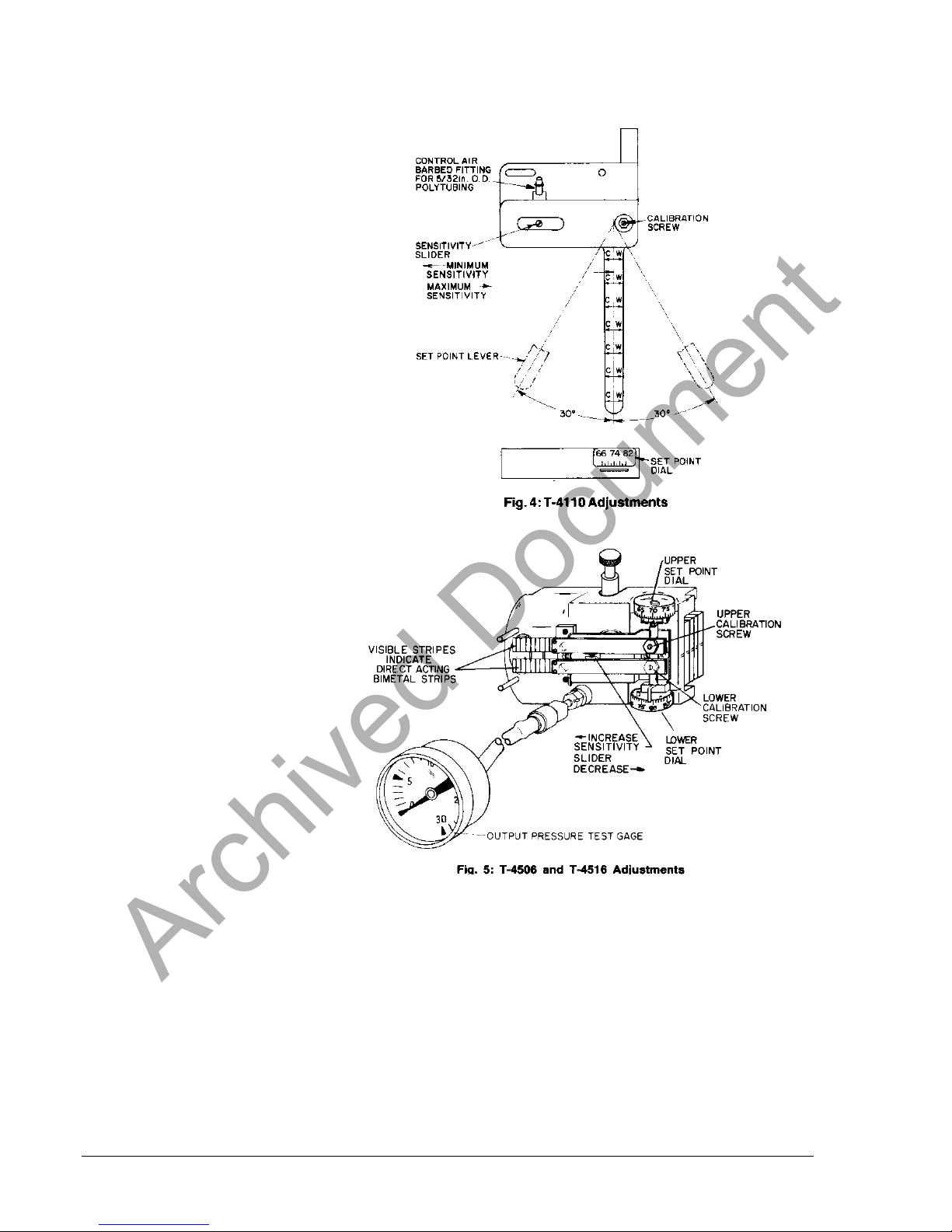
T-4506 and T-4516
Set Point Adjustment
Usually the day set point is made
on the lower element with a
15 psig (105 kPa) supply
pressure and the night set point
is made on the upper element
with a 20 psig (140 kPa) supply
pressure. If your application is
different, use the proper element
and supply pressure for the
particular application. The
T-4506 is furnished with DAY and
NIGHT labels which can be
applied to the appropriate
element.
Day Set Point Adjustment
(See Fig. 5)
1. Insert the test gage.
2. Furnish 15 psig supply
pressure for day control
(lower dial).
3. Note the ambient
temperature in the space.
4. Turn the lower set point dial
to that temperature.
5. Turn the lower calibration
screw until the output
pressure is at the mid spring
range of the controlled
device.
4 T-4000 Technical Bulletin
6. Turn the lower set point dial
to the desired day set point.
Night Set Point Adjustment
1. Furnish 20 psig supply
pressure for night control
(upper dial).
2. Note the ambient
temperature in the space.
3. Turn the upper set point dial
to that temperature.
4. Turn the upper calibration
screw until the output
pressure is at the mid spring
range of the controlled
device.
5. Turn the upper set point
dial to the desired night set
point.
6. Restore the supply pressure
to the desired cycle.
Page 5

T-4600 Set Point
Archived Document
Adjustment
The T-4600 is furnished with
HEATING and COOLING labels.
Apply each label to the
appropriate element to avoid
error in calibration or hook up.
Heating Set Point Adjustment
(See Fig. 6)
1. Insert the test gage.
2. Furnish restricted supply air
to the instrument.
3. Note the ambient
temperature in the space.
4. Turn the heating set point
dial to that temperature
(match it with the arrow).
T-4756 Set Point
Adjustment
Usually the heating set point is
made on the lower element with
a 15 psig (105 kPa) supply
pressure and the cooling set
point is made on the upper
element with a 20 psig (140 kPa)
supply pressure. If your
application is different, use the
proper element and supply
pressure for the particular
application. The T-4756 is
furnished with HEATING and
COOLING labels which can be
applied to the appropriate
element.
Heating Set Point Adjustment
(See Fig. 7)
1. Insert the test gage.
2. Furnish 15 psig supply
pressure for heating control
(lower dial).
3. Note the ambient
temperature in the space.
4. Turn the lower set point dial
to that temperature.
5. Turn the lower calibration
screw on the heating
element until the output
pressure is at the mid spring
range of the controlled
device.
6. Turn the lower set point dial
to the desired heating set
point.
5. Turn the calibration screw on
that element until the output
pressure to the heating
apparatus is at the mid
spring range of the
controlled device.
6. Turn the heating set point
dial to the desired set point.
Cooling Set Point Adjustment
Repeat the procedure for heating
adjustment on the other element.
Remember to use the other test
port and the proper value in step
5 for the mid spring range of the
controlled device.
Fig. 7: T-4756 Adjustments
Cooling Set Point Adjustment
1. Insert the test gage.
2. Furnish 20 psig supply
pressure for cooling control
(upper dial).
3. Note the ambient
temperature in the space.
4. Turn the upper set point dial
to that temperature.
5. Turn the upper calibration
screw on the cooling
element until the pressure is
at the mid spring range of
the controlled spring range
of the controlled device.
6. Turn the upper set point dial
to the desired temperature.
7. Restore the supply pressure
for the desired cycle.
T-4000 Technical Bulletin 5
Page 6

Switchover Point
Archived Document
Adjustment for T-4506,
T-4516, and T-4756
The above thermostats are
factory set to switch from one
element to the other at 17 psig
for a typical 15-20 psig supply
system. If a different supply
system is to be used, proceed
with the following instructions to
reset the switchover point to a
value between the two supply
pressures. The switch point is
adjustable from 15 to 20 psig
(105 to 140 kPa).
1. Remove the controller from
the mounting bracket.
2. Connect a variable pressure
source to the supply
connection and attach a
gage to the output
connection.
3. Set the supply pressure to
15 psig and rotate the
lower dial to produce
approximately 5 psig
(35 kPa) on the output gage.
4. Increase the supply pressure
to 20 psig and rotate the
upper dial to produce
approximately 15 psig on the
output gage.
5. Set the supply pressure to
the desired switchover point.
6. Slowly turn the switchover
adjusting screw (see Fig. 8)
clockwise to increase or
counterclockwise to
decrease the switch point
until the output changes.
Note: Do not turn the
switchover adjusting
screw more that 3-1/2
complete revolutions in
either direction.
7. Recheck the switchover
point by increasing and
decreasing the supply
pressure over the switch
point to see that switchover
occurs at the desired value.
8. Remove the gage and tubing
and replace the instrument
on the mounting bracket.
6 T-4000 Technical Bulletin
Page 7

Notes
Archived Document
T-4000 Technical Bulletin 7
Page 8

Notes
Archived Document
Controls Group
507 E. Michigan Street
P.O. Box 423
Milwaukee, WI 53202 Printed in U.S.A.
8 T-4000 Technical Bulletin
 Loading...