

Page 1
14-1104-0, Rev.
A
T-3100, T-3200, and T-3300 Series Controllers
The T-3100 and T-3300 Series proportional action
pneum
temperature in accordance with the return air
temperature in terminal air conditioning units. The
T-3200 Series of pneumatic thermostats are designed
to control pneumatic actuators in single temperature,
dual pressure applications.
The T-3111 and T-3311 Series controllers are
combination pneumatic thermostats and valve
actuators. The T-3111 provides proportional control of
a steam or water valve on a single temperature
application, while the T-3311 provides control in
dual temperature, dual pressure applications.
atic thermostats are designed to maintain
Product/T
echnical Bulletin
Issue Date March 2016
WARM
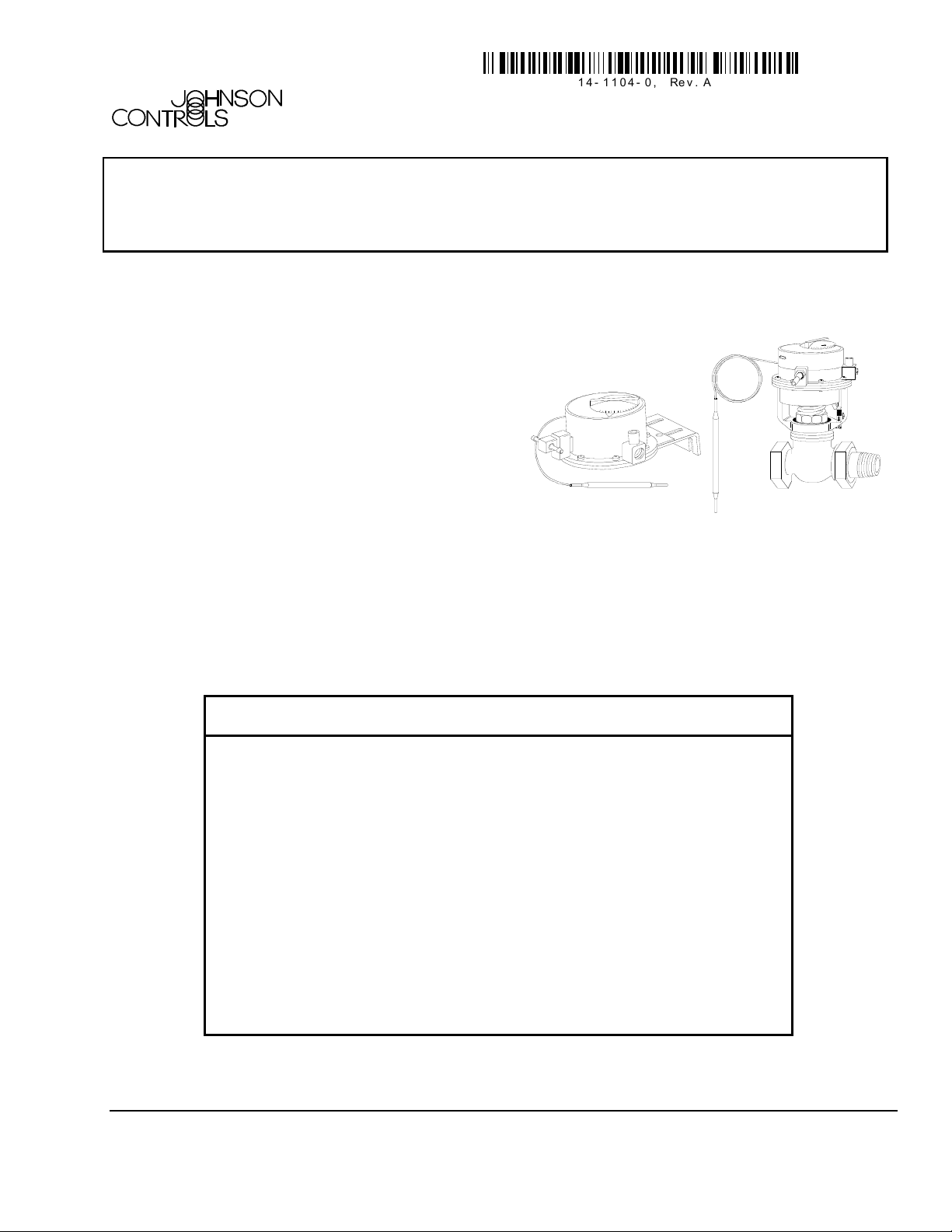
Figure 1: T-3100 Remote Mounted Thermostat and
T-3311 Valv
e Top Thermostat
Models are Available in
Direct or Reverse Acting
Models Available with an
Valve Top Models
2016 Johnson Controls, Inc.
©
Part No. 14-1104-0, Rev. A
Code No. LIT-7171156
Features and Benefits
Direct-reverse Acting or
Reverse-direct Acting
Models Av
ailable wi
Filled Temperature
Measuring Elements
External or Concealed
Setpoint Adjusting Screw
Compatible with
VG7000 Series Valves
th Liquid
Allows seasonal change over from cooling to
heating or heating to cooling automatically
Suits heating or cooling applications
Field adjust
able or concealed to maintain system
design as commissioned
The T-3111 and T-3311 are direct replacements
for the T-3110 and T-3310 Series Valve Top
Actuators
1
Page 2
rdering Information
O
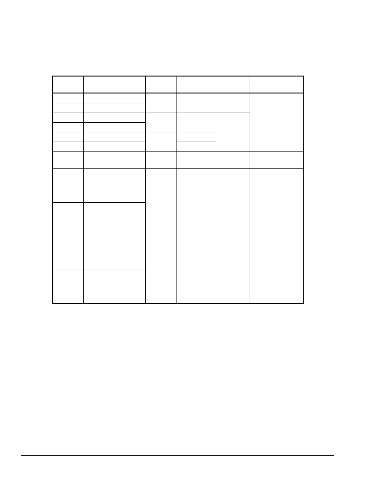
Table 1: Ordering Information
Code
Number
T-3100-2
T-3100-3
T-3111-1
T-3111-2
T-3111-3
T-3111-6
T-3200-1
T-3300-1
T-3300-2
T-3311-1
T-3311-2
Direct Acting
Reverse Acting
Direct Acting
Reverse Acting
Direct Acting
Direct Acting Concealed
DIR at 15 and 20 psig
(103/138 kPa)
DIR at 15 psig
(103 kPa)
REV at 20 psig
(138 kPa)
DIR at 20 psig
(138 kPa)
REV at 15 psig
(103 kPa)
DIR at 15 psig
(103 kPa)
REV at 20 psig
(138 kPa)
DIR at 20 psig
(138 kPa)
REV at 15 psig
(103 kPa)
Action
(Proportional)
Element
Bulb External Remote Single Temperature
Bulb External
Averaging External Valve Top Single Pressure
Averaging Concealed Remote
Bulb External Remote
Bulb External Valve Top Dual Temperature
Setpoint
Adjustment
Mounting Application
Single Temperature
Dual Pressure
Dual Temperature
Dual Pressure
Dual Pressure
2 T-3100, T-3200, and T-3300 Series Controllers Product/Technical Bulletin
Page 3
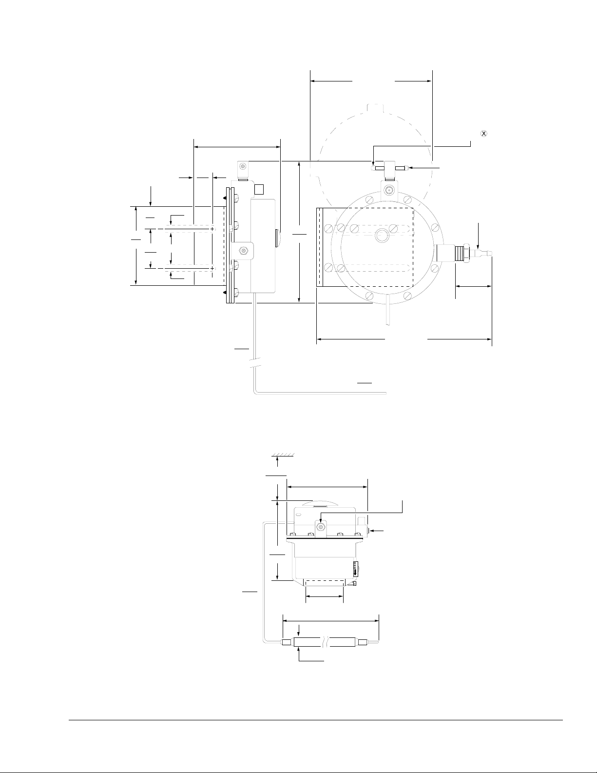
imensions
D
76
3
3/4
19
1-1/2
38
5/8
16
1/4
6
1/4
6
Capillary Length
3-3/8
86
42
1067
4-3/4
121
Extends to maximum
4-3/4
121
Extends to maximum
6-9/16
167
5/16
Diameter
8
5-1/8
130
5-11/16
144
Subordinate
Connection 1/8 inch
NPT, Internal Thread
Supply Air to
Restrictor
Branch
Restrictor
Branch
Marked
Control Air
3/4
19
8-11/16
220
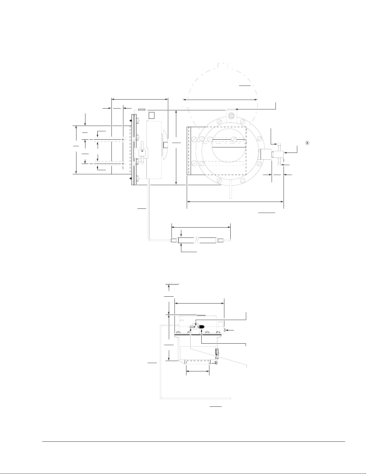
Figure 2: Dimensions and Mounting Details for T-3100, in./mm
3-1/16
Capillary Length
78
4-7/16
113
18
457
Averaging Element Length
4-3/4
120
2-1/4
57
Barbed
Restrictor Tee
Subordinate
Connection
1/8 inch NPT,
Internal Thread
Sealing Cap
(Open Branch)
Supply Air Connection
(Restrictor Branch)
96
2438
Figure 3: Concealed Adjustment for T-3111, in./mm
T-3100, T-3200, and T-3300 Series Controllers Product/Technical Bulletin 3
Page 4
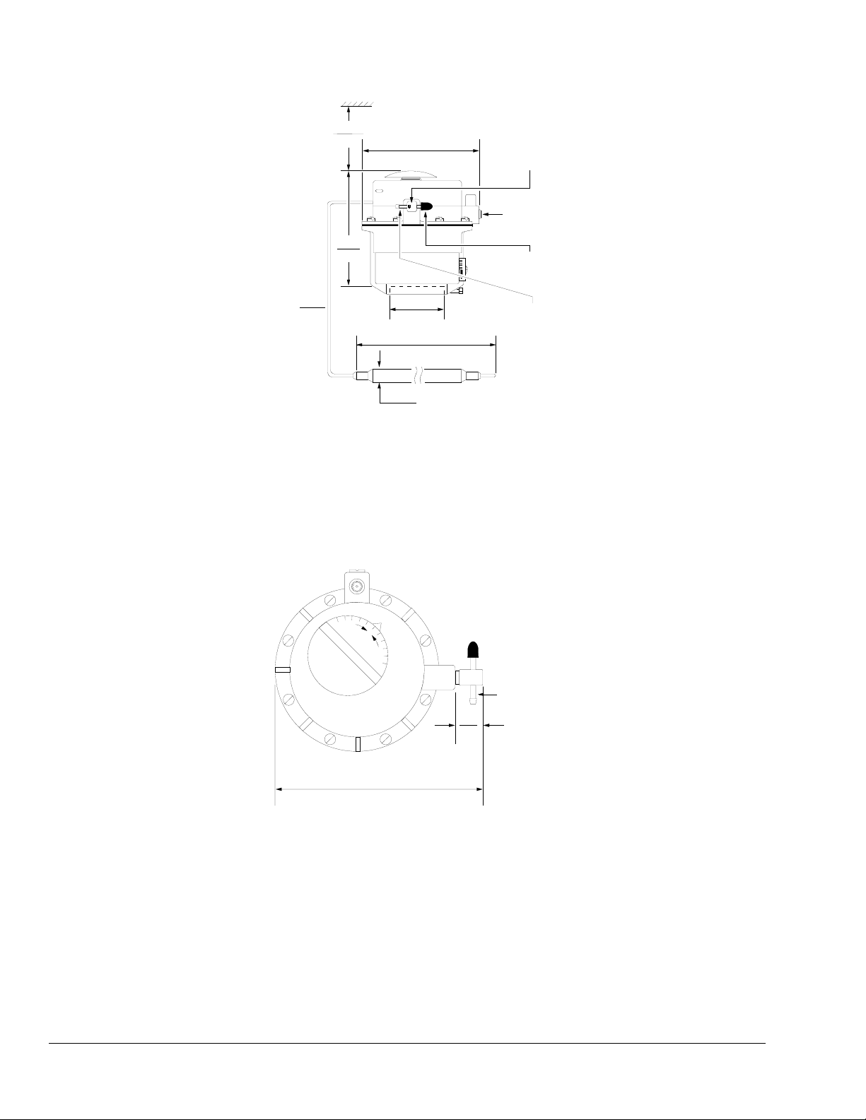
3-3/16
80
4-9/16
116
4-3/4
121
Barbed
Restrictor Tee
Subordinate
Connection
1/8 inch NPT,
Internal Thread
Sealing Cap
(Open Branch)
Capillary Length
42
1067
2-1/4
57
Supply Air Connection
(Restrictor Branch)
6-9/16
167
5/16
Diameter
8
Figure 4: Exposed Adjustment for T-3111, in./mm
O
L
O
C
W
A
R
M
Supply
Air
3/4
19
5-3/16
132
Figure 5: Mounting Details for T-3111, in./mm
4 T-3100, T-3200, and T-3300 Series Controllers Product/Technical Bulletin
Page 5
5/8
16
3-1/8
79
4-3/4
121
to maximum
5-1/8
130
Barbed Restrictor
Tee Suppl y
(Restrictor Branch)
Marked
Output
(Open Branch)
76
3
3/4
19
1-1/2
38
1/4
6
5-1/2
140
1/4
6
8-13/16
224
Capillary Length
18
457
Averagi n g E l em ent Length
5-13/16
148
96
2438
to maximum
Figure 6: Dimensions and Mounting Details for T-3200, in./mm
3-1/16
78
4-3/4
121
Supply Air
Straight Connector
for 1/4 inch O.D.
Poly ethylene T ub ing
Switching Air
Connection
13/16
21
4-9/16
116
Capillary Length
42
1067
2-1/4
5/16
8
57
6-9/16
167
Diameter
Figure 7: Exposed Dimensions for T-3311, in./mm
T-3100, T-3200, and T-3300 Series Controllers Product/Technical Bulletin 5
Subordinate
Connection
1/8 inc h N P T ,
Internal Thread
Page 6

76
3
3/4
19
1-1/2
38
5/8
16
1/4
6
1/4
6
Capillary Length
3-3/8
86
42
1067
5-9/16
141
4-3/4
121
to maximum
5-13/16
148
to maximum
5-1/8
130
Output
Air Connection
Supply Air
Connection
13/16
21
8-13/16
224
6-9/16
167
5/16
Diameter Bulb
8
Figure 8: Dimensions and Mounting Details for T-3300, in./mm
L
O
O
C
H
E
A
T
3/16
21
5-5/16
135
Figure 9: Mounting Details for T-3311, in./mm
6 T-3100, T-3200, and T-3300 Series Controllers Product/Technical Bulletin
Page 7

nstallation Procedures
I
Tubing Installation
The T-3100, T-3200, and T-3300 Series Thermostats
are supplied with barbed fittings for the supply and the
output air connections. It is recommended that Type
“FR” polyethylene tubing be used on the barbed
fittings.
Note: Cut tubing off square for a good fit on the
barbed fitting.
If “HP” or copper tubing is used, the barbed fitting
must be removed and replaced with a compression
fitting and an in-line restrictor when necessary.
Note: Figure 10 illustrates a copper tubing
installation; “HP” tubing installation is the
same except the brass ferrule is replaced with
a thermoplastic ferrule, which is supplied with
the R-3710-1007 restrictor.
.007 inch In-Line
Restrictor with O-Ring
1/8 inch NPT, Internal Thread
Brass Ferrule
(Field F ur ni shed)
Air
Flow
1/4 inc h O.D.
Soft Copper Tubing
Compre ssion
Nut
Supply Air Connecti on
Standard Compression
Fitting (Field Furnished)
Figure 10: Copper Tubing Installation
(Use R-3710-1007 In-Line Restrictor)
Route the capillary so it is not in contact with
extremely high or low temperature sources such as
steam lines, water pipes, or coils. Be sure to route the
element and capillary so that routine maintenance can
be performed on the terminal unit without disturbing
the element.
Bulb Element
In most cases, a bulb element will be installed in the
return air chamber of the terminal air unit in the
following manner:
1. Install the element behind the protective screen or
grille and in a location where normal maintenance
may be performed on the unit without interference.
2. Be sure the bulb will sense only the return air and
will not be influenced by other temperatures.
3. Secure the bulb using holder, T-275-100 (ordered
separately) which can be hung or fastened in
place and bent to the desired position.
Holder
Bulb
5/16
Diameter Hole
8
Sensing Elements
Both the bulb and the averaging sensing element must
be carefully located so the elements measure only the
intended air temperature. The majority of terminal air
condition units are very compact and little clearance
exists between coils. Also, the air flows are of widely
varying temperature. Before selecting an element
location, study the unit interior and make certain that
the sensing element will not be affected by
undesirable temperatures or mechanical damage.
Avoid extremely sharp bends in the capillary which
could obstruct the liquid flow.
T-3100, T-3200, and T-3300 Series Controllers Product/Technical Bulletin 7
8
203
Figure 11: Bulb Element Holder Dimensions,
in./mm (T-275-100, ordered separately)
Page 8

Averaging Element
In most cases, an averaging element will be installed
in the air chamber of the terminal air unit in the
following manner:
1. Install the element in a serpentine fashion across
the top of the unit coil.
2. Secure the element along the entire length by
using holders, T-275-101 (ordered separately), so
that no part of the element touches the coil. The
holder is very flexible and can be bent to any
desired position.
3. On face and bypass units, the element must be
placed in the space where a mixing of coil
discharge air (face) and coil bypass air takes
place. Install the element as close as possible to
the bottom side of the discharge air grille. The
element should be secured by using holders
(T-275-101, ordered separately) fastened to the
unit casing.
For ASHRAE Cycle III applications, the element
must be installed in the mixed air (outside and
return) rather than in the discharge air. Install the
element so it will receive the best possible
sampling of the mixture temperature using holders
(T-275-101, ordered separately) fastened to the
unit casing.
Bend prongs around
bulb or capillary.
alibration Procedures
C
All Johnson Controls instruments are carefully tested
and calibrated at the factory before shipment. If field
calibration is required, it should not be started until all
installation procedures are complete. If, during
calibration, the temperature at the measuring element
fluctuates, place the element in a stable, wellcontrolled temperature area such as a bucket of water,
preferably 75F (24C) for controllers and
56F (13C) for low limit controllers.
Be sure the supply air to the instrument is clean and
free of moisture. The adjusting dial is graduated in
1F increments and can be removed with a flexible
hex head screwdriver (JC 5309, ordered separately).
It is recommended that the middle graduation be used
to represent the desired temperature setpoint.
The adjusting screw for externally adjusted,
Direct Acting (DIR) models is located inside the dial
post and is accessible by removing the dial (refer to
Figure 13, Detail A). For DIR models with concealed
adjustment, it is necessary to remove the small metal
button in the cover (refer to Figure 13, Detail B). A
calibration tool (T-4002-5009, ordered separately)
should be used to adjust the setpoint on these models.
It is necessary to remove the dial and cover for models
with either Reverse Acting (REV) or low limit
adjustments. Use a calibration tool (T-4002-5009,
ordered separately) for Reverse Acting adjustment of
the T-3100 and T-3300 Series Thermostats (refer to
Figure 13, Detail C).
Be sure each T-3100 and T-3111 Thermostat has a
0.007 inch in-line restrictor installed in the supply air
connection. The T-3200 instruments should have a
0.007 inch in-line restrictor in the air line between the
instrument and the room thermostat.
3/16
5
25
2-1/4
57
1
Twist here
if required.
Slip pron gs
over coil fin.
Coil Fin
Figure 12: Averaging Element Holder Dimensions,
in./mm (T-275-101, ordered separately)
8 T-3100, T-3200, and T-3300 Series Controllers Product/Technical Bulletin
Page 9

Switch Stack
Not Furnished on
T-3100 Series
Temperature Set P oi n t
Adjusting Dial
Flexible Driver
JC 5309 (Ordered Separately)
Low Limit Setpoint
Adjustment on Two
Element Controllers
Direct Acting
Set Point Adjustment
(Detai l A )
(Out put Test Port)
Test Co nn ec tion
For Concealed
or Remote
Adjustment Models
For External
Adjustment Models
Reverse Acting
Set Point Adjustment
(Detai l C)
Figure 13: Setpoint Adjusting Features
Recalibration Tool
JC 5360 (o rd er ed s e par ately)
Direct Acting
Set Point Adjustment
(Detail B)
T-3100, T-3200, and T-3300 Series Controllers Product/Technical Bulletin 9
Page 10

Temperature Setpoint Adjustment
For T-3100 and T-3200 Series follow
Steps 1 through 7.
1. Supply the instrument with the proper supply air
pressure.
2. Insert the test gauge (JC 5310, ordered
separately) and the probe assembly (JC 5361,
ordered separately) into the output test port.
Note: For Reverse Acting thermostats it will be
necessary to remove the cover in order to turn
the setpoint adjustment screw.
3. Turn the setpoint adjustment screw until the
pressure reading is approximately in the middle of
the operating range of the actuator. For example,
a 5 to 10 psig operating range would require an
output pressure reading of 7.5 psig.
4. Remove the test gauge and probe assembly.
5. Determine the temperature at the measuring
element.
6. Place the dial on the dial post (do not tighten) and
position it to the temperature at the element.
Remember that each dial increment represents
one Fahrenheit degree. For models with
concealed adjustment, use recalibration tool
JC 5360 (ordered separately).
7. Tighten the dial and turn it to the desired setpoint.
Example: If the desired temperature setpoint is
75F and the temperature at the
element is 71F, then place the dial on
the dial post (do not tighten) and
position it to 71F or four graduations
(75F-71F = 4F) clockwise from the
middle graduation (75F), the desired
setpoint.
For T-3300 Series proceed as follows:
1. Supply the instrument with the appropriate air
pressure for the Direct Acting (DIR) operation.
2. Insert the test gauge (JC 5310, ordered
separately) and the probe assembly (JC 5361,
ordered separately) into the test port
(as illustrated in Figure 14).
3. Remove the knob and cover.
4. Turn the DIR screw until the output pressure is in
the middle of the actuator operating range.
5. Change the supply air pressure to that required for
the Reverse Acting (REV) operation.
6. Turn the REV adjusting screw until the output
pressure is in the middle of the actuator operating
range.
7. Remove the test gauge and probe assembly.
8. Determine the temperature at the element.
9. Attach the cover.
10. Place the dial on the dial post (do not tighten) and
position it to the temperature at the element.
11. Tighten the dial and turn to the desired setpoint.
Note: If the setpoints of several instruments are to
be adjusted before switching the supply
pressure, be sure that the temperature at the
element will not change during both stages of
adjustment.
Note: For T-3200 Series the low limit setpoint is
56F. Use calibration tool T-4002-5009
(ordered separately). Each graduation is
9F (5C).
10 T-3100, T-3200, and T-3300 Series Controllers Product/Technical Bulletin
Page 11

Test P r ob e A s sembly
(JC 5361 , or de red s ep ar ately)
(JC 5310, ordered separately)
Test Gauge
Output Pressure
Test Port
1/8 inc h
NPT, Internal
Thread
15
10
20
5
25
30
0
Figure 14: Test Gauge
Temperature at Element
71°F ( 22°C)
e
s
i
w
k
c
o
l
C
H
E
L
O
O
C
A
T
75°F (24° C) Desired
Temperature Setting
Mid-point of Dial
75°F (24°C)
Pointer
H
E
L
O
O
C
A
T
Figure 15: Temperature Setpoint Dial
T-3100, T-3200, and T-3300 Series Controllers Product/Technical Bulletin 11
Page 12

Restricted Adjustment
The dial pointer on externally adjusted models has
tabs which are factory set to restrict the dial
adjustment to a span of 15F (7.5F on either side of
the pointer). The restriction can be changed to the
spans indicated in Table 2 by bending up the
appropriate tabs and flattening the factory set tabs.
Table 2: Span Adjustment
Span Tab
F C F C
20 11.1 + 10 + 5.6
15 8.3 + 7.5 + 4.2
10 5.6 + 5 + 2.8
5 2.8 + 2.5 + 10
10°F
7.5°F
5°F
2.5°F
10°F
7.5°F
5°F
2.5°F
Figure 16: Restricted Adjustment
aintenance and
M
Troubleshooting Procedures
These instruments are designed so that a minimum of
routine maintenance is required. The following
procedures should be used to ensure proper operation
and to locate malfunctioning components:
1. Check all air lines, connections
for air leaks. Make sure that the in-line restrictors
are not defective.
2. Check the operation of the thermostat to be sure it
is passing the correct control signal and that it is
functioning properly. Make sure it has the proper
supply air pressure and that air is exhausting from
the control port. The port must exhaust
continuously to ensure proper operation of the
thermostat.
3. Check that the temperature measuring element
has not been damaged or moved from its intended
sensing position.
4. Check that the valve packing nut is tight enough to
prevent leaks, but not so tight that the packing
becomes distorted and binds the stem; usually
finger tight is sufficient. If the valve is leaking
around the centerpiece, tighten it with the
appropriate wrench.
5. Verify that the valve seats completely when the
actuator is fully stroked. If there is fluid flow after
the plug is seated, the seat, plug, or disc may be
worn or scored and should be repaired or
replaced.
, and diaphragms
6. If there are subordinate actuators, make sure the
actuators are operating in the proper sequence
and adjusted correctly.
12 T-3100, T-3200, and T-3300 Series Controllers Product/Technical Bulletin
Page 13

ccessories
A
Table 3: Accessories (Order Separately)
Description Code Number
Hex Head Flexible Screwdriver JC 5309
Control Line Test Gauge and
Adaptor
Recalibration Tool JC 5360
Test Probe Assembly JC 5361
Averaging Element Holder for
3 inch (76 mm) Coil
(See Figure 17.)
Restrictor Tee (.007 inch) R-3710-1007
“B” Bulb Holder T-275-100
Averaging Element Holding Clip T-275-101
Supply Inlet Filter
(Order in multiples of 100.)
Calibration Tool T-4002-5009
Averaging Element Holder for
Radius Bends (minimum 3-1/2 in.
(See Figure 18.)
Diaphragm for Exposed Actuator
V-3000-1 only
JC 5310
Order QEO-1 from
Temperature Control
Specialties
2800 Laura Lane
Middleton, WI 53562
(608) 836-9034
T-3100-605
TE-6001-8
V-3000-600
Figure 17: QEO-1, Averaging
Element Holder
Figure 18: TE-6001-8,
Averaging Element Holder
T-3100, T-3200, and T-3300 Series Controllers Product/Technical Bulletin 13
Page 14

epair Procedures
R
Actuators
To replace the diaphragm, follow Steps 1 through 7
below.
1. Remove the eight screws holding the thermostat
to the integral actuator.
2. Lift the thermostat exposing the diaphragm and
remove the piston.
3. Turn the new diaphragm inside out and place it
over the piston. Smooth out all of the wrinkles and
release any air trapped between the head of the
piston and the diaphragm, then pull the flange up.
The diaphragm will assume its shape, as
illustrated in Figure 19.
4. On piston top valve actuators, place the piston
straight within the new diaphragm and insert into
the bell housing.
5. Replace the thermostat.
Thermostat
Diaphragm
V-3000-600
Piston
Spider
Figure 19: Diaphragm Installation for
T-3111 and T-3311 Series
6. Replace all the screws and tighten equally.
7. Place the instrument in operation and check its
action.
14 T-3100, T-3200, and T-3300 Series Controllers Product/Technical Bulletin
Page 15

pecifications
S
Product T-3100, T-3200, and T-3300 Series Controllers
Models See Table 1.
Proportional Action See Table 1.
Maximum Supply Pressure
Ambient Temperature Limits
Supply
Air Connections
S
ubordinate
Ty
Element
Range
Span 20F (11C) Maximum
Dial Range
Marking “Cool-Warm,” Graduated in one degree “F” Increments
Sensitivity
Remote Bulb
veraging Bulb T-3111
A
Factory Setpoint T-3200 56F (13C)
Continued on next page. . .
* The maximum length of 5/32 inch tubing is 15 feet. It is recommended that 1/4 inch tubing is used at all times to ensure
proper switchover.
25 psig (172 kPa)
-20 to +150F (-29 to 66C)
T-3100
T-3111
T-3200
T-3311
-3300
T
All Models
T
-3111
T-3111 and
pe
T-3200
T-3100
T-3300
T-3311
T-3100
T-3200
T-3300
T-3311
T
-3111
All Models
Except
T-3200
T-3100
T-3111
T-3300
T-3311
T-3200
T-3100 75F (24C)
T-3300 75F (24C)
Barbed Restrictor Tee for 1/4 inch O.D. Polyethylene Tubing
Straight Connector for 1/4 inch O.D. Polyethylene Tubing;
1/8 inch NPT Barbed Fitting for 5/32 or 1/4 inch O.D.
Polytubing*
1/8 inch NPT, Internal Thread
Bulb with 42 inch (1067 mm) Capillary
8 ft (2438 mm) Averaging with 18 inch (457 mm) Capillary
Bulb with 42 inch (1067 mm) Capillary
60 to 150F (16 to 66C)
Bulb, 60 to 150F (16 to 66C)
Averaging, 30 to 175F (-1 to 80C)
Factory Set at + 7.5F (+ 4C)
2.5 psi/F (31 kPa/C)
0.5 psi/F (31 kPa/C)
T-3100, T-3200, and T-3300 Series Controllers Product/Technical Bulletin 15
Page 16

pecifications (Cont.)
S
Body
Cover
Material
Accessories (Order Separately) See Table 3.
The performance specifications are nominal and conform to acceptable industry standards. For application at conditions beyond these specifications,
consult the local Johnson Controls office. Johnson Controls, Inc. shall not be liable for damages resulting from misapplication or misuse of its products.
Yoke
Diaphragm
Finish Green Lacquer
All Models
All Models
T-3111 and
T-3311
T-3111 and
T-3311
Die Cast Aluminum
Die Cast Zinc
Die Cast Aluminum
Molded Synthetic Rubber
European Single Point of Contact: NA/SA Single Point of Contact: APAC Single Point of Contact:
JOHNSON CONTROLS
WESTENDHOF 3
45143 ESSEN
GERMANY
JOHNSON CONTROLS
507 E MICHIGAN ST
MILWAUKEE WI 53202
USA
JOHNSON CONTROLS
C/O CONTROLS PRODUCT
MANAGEMENT
NO. 22 BLOCK D NEW DISTRICT
WUXI JIANGSU PROVINCE 214142
CHINA
Controls Group
507 E. Michigan Street
P.O. Box 423
Milwaukee, WI 53201 Printed in U.S.A.
16 T-3100, T-3200, and T-3300 Series Controllers Product/Technical Bulletin
 Loading...