

Johnson Controls System 450 Series, System C450CQN-1, System C450CPN-1 Installation Instructions Manual
Page 1

Figure 1: System 450 Module Dimensions, mm (in.)
127
(5)
4
Screw
Slots
11
(7/16)
(2-3/8)
75
(2-15/16)
1/2 in. No minal
Trad e Size
Conduit Hole
22
(7/8)
40
(1-9/16)
DIN Rail
Clips
FIG:sys450_dims
System 450™ Series Control Modules with Analog Outputs
Installation Instructions
C450CPN-1
C450CQN-1
Part No. 24-7664-2780, Rev. A
Issued December 10, 2009
Application
IMPORTANT: Use this System 450 Series Control
Module with Analog Output only as an operating
control. Where failure or malfunction of the System
450 control module could lead to personal injury or
property damage to the controlled equipment or
other property, additional precautions must be
designed into the control system. Incorporate and
maintain other devices, such as supervisory or
alarm systems or safety or limit controls, intended to
warn of or protect against failure or malfunction of
the System 450 control module.
System 450 is a family of modular, digital electronic
controls that is easily assembled and set up to provide
reliable temperature, pressure, and humidity control for
a wide variety of Heating, Air Conditioning, Ventilation,
and Refrigeration (HVACR), and commercial/industrial
process applications.
The System 450 Series allows you to configure custom
application-specific control systems with up to three
input sensors and ten (relay and/or analog) outputs,
including control systems that can monitor and control
temperature, pressure, and humidity applications
simultaneously.
You can easily install and quickly configure a
stand-alone System 450 control module and sensor in
the field as a replacement control for almost any
temperature, pressure, and humidity control.
C450CxN-1 models are analog output control modules
with Liquid Crystal Display (LCD) and four-button touch
pad User Interface (UI) that allows you to set up a
System 450 control system. C450CPN-1 models
provide one self-selecting analog output, C450CQN-1
models provide two self-selecting analog outputs.
Refer to the System 450 Series Technical Bulletin
(LIT-12011459) for more detailed information on
designing, installing, setting up, and troubleshooting
System 450 Series control systems. The System 450
technical bulletin can be accessed and downloaded on
the Johnson Controls® Online Product Litera tu re Web
site at the following Web address:
http://cgproducts.johnsoncontrols.com/default.aspx
13
(1/2)
(3/16)
(Four)
61
61
(2-3/8)
Mounting
Location Considerations
Observe the following System 450 location guidelines:
• Ensure that the mounting surface can support the
module assembly, mounting hardware, and any
(user-supplied) panel or enclosure.
• Mount the modules in upright and plugged together
in a horizontal row where possible. DIN rail
mounting is highly recommended.
• Mount modules on flat even surfaces.
• Allow sufficient space for wires and connections.
• Mount the modules in locations free of corrosive
vapors and observe the ambient operating
conditions in the Technical Specifications
• Do not mount the modules on surfaces that are
prone to vibration or in locations where radio
frequency or electromagnetic emissions may
cause interference.
• Do not install the modules in airtight enclosures.
• Do not install heat-generating devices in an
enclosure with the modules that may cause the
temperature to exceed the ambient operating limit.
.
System 450™ Series Control Modules with Analog Outputs Installation Instructions 1
Page 2
Mounting System 450 Modules
!
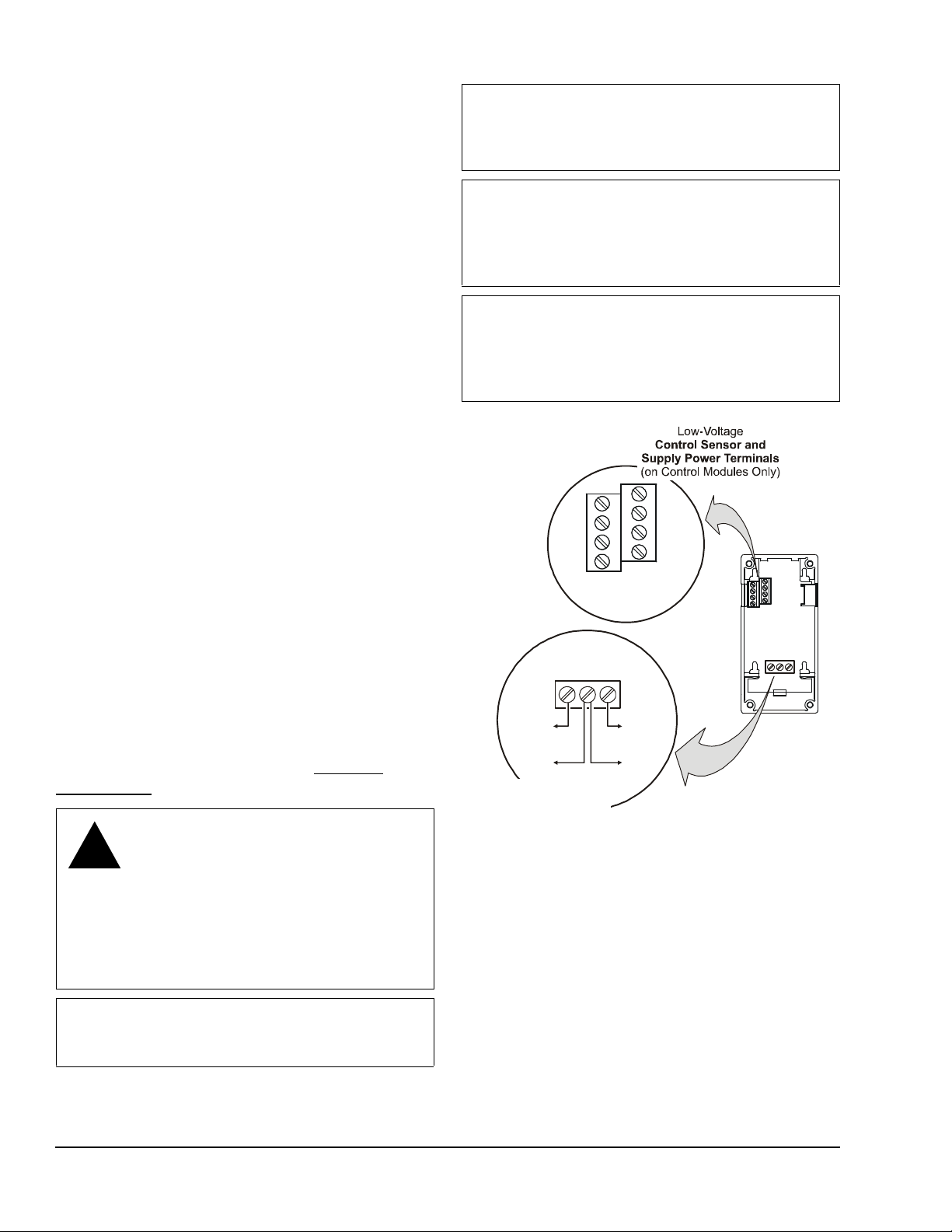
Figure 2: C450CxN-1 Wiring Terminals
with Analog
Outputs
(C450CQN-1)
A
A
AO2
COM
AO1
Analog
Controlled
Device
Analog
Device
+
__
+
Low-Voltage
Analog Output Terminals
C
5V
24V
C
Sn1
C
Common terminals (C)
are internally
connected.
Mount System 450 modules on 35 mm DIN rail
(recommended) or directly to an even wall surface. To
mount the modules on DIN rail:
1. Provide a section of 35 mm DIN rail that is longer
than the module assembly width, and mount the
DIN rail horizontally in a suitable location using
appropriate mounting hardware/fasteners.
2. Clip the control module on the rail, position the
upper DIN rail clips on the top rail, and gently snap
the lower clips on to the rail.
3. Clip the remaining modules to the right of the
control module on to the DIN rail and plug together.
To direct mount modules to wall surfaces:
1. Plug the modules together, remove the module
covers, place the assembly against wall surface
horizontally in a suitable location, and mark the
mount hole locations on the surface.
IMPORTANT: Do not exceed the System 450
module electrical ratings. Exceeding module
electrical ratings can result in permanent da mage to
the modules and void any warranty.
IMPORTANT: Do not connect 24 VAC supply
power to the System 450 modules before finishing
wiring and checking all wiring connections. Short
circuits or improperly connected wires can result in
damage to the modules and void any warranty.
IMPORTANT: Run all low-voltage wiring and
cables separate from all high-voltage wiring.
Shielded cable is strongly recommended for input
and output cables that are exposed to high
electromagnetic or radio frequency noise.
2. Install appropriate screw fasteners, leaving screw
heads approximately one to two turns away from
flush to the surface.
Sn2
Sn3
FIG:sys450_anlg_c ntrl_wi r
3. Place the assembly over screw heads and on the
mounting slots, and carefully tighten mount screws.
Note: If you mount the modules on an uneven
surface, do not damage the housings when
tightening mounting screws. Use shims/washers to
mount module assembly evenly on the surface.
COM
O2
O1
Refer to the control sensor installation instructions for
information on locating and mounting control sensors.
Wiring
See Figure 2 and Table 1 for electrical termination
Controlled
System 450
Control Module
locations and wiring information. See Technical
Specifications on page 11 for electrical ratings.
WARNING: Risk of Electric Shock.
Disconnect or isolate all power supplies
before making electrical connections.
More than one disconnect or isolation
may be required to completely
de-energize equipment. Contact with
components carrying hazardous voltage
can cause electric shock and may result
in severe personal injury or death.
IMPORTANT: Use copper conductors only. Make
all wiring in accordance with local, national, and
regional regulations.
System 450™ Series Control Modules with Analog Outputs Installation Instructions2
Page 3
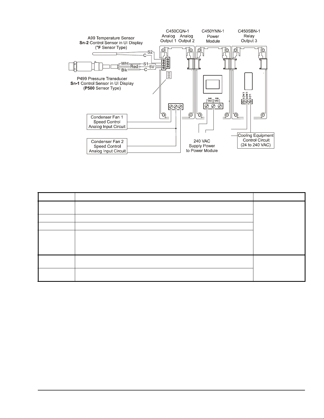
Figure 3: Example System 450 Heat/Cool System with Condenser Fan Speed Control
Analog Output
Signal
Active/Passive Sensor DIP Switches
DIP Switch 1 is Off; switch 2 is ON.
COM
AO2
AO1
FIG:sys450_app_anlg_exmpl
L1
L1 L2
L2
Table 1: System 450 Analog Output Control Module Terminal Wiring Information
Label Terminal Function Wire Sizes
24V Accepts 24 V AC supply power, when a C450YNN power module is not connected,
and provides power terminal for 24 VAC (humidity) sensors.
5V Provides 5 VDC power for active sensors.
S1, S2, S3 Accepts passive or active (0-5 VDC) input signals from control sensors.
C
(Three
Terminals)
Provide low-voltage Common connections for 24 VAC power and passive or active
sensors connected to the 5V, Sn1, Sn2, and Sn3 terminals.
Note: The three C terminals are connected internally and can be connected to
ground in the field.
AO1,
AO2
Provides a self-detecting analog output signal in conjunction with the COM
terminal; either 0–10 VDC or 4–20 mA.
COM Provides a self-detecting analog output signal in conjunction with the AO1 or AO2
terminal; either 0–10 VDC or 4–20 mA.
2
0.8 mm
28 AWG to 16 AWG
0.08 mm
28 AWG to 16 AWG
to 1.5 mm
2
to 1.5 mm
2
2
System 450™ Series Control Modules with Analog Outputs Installation Instructions 3
Page 4
4
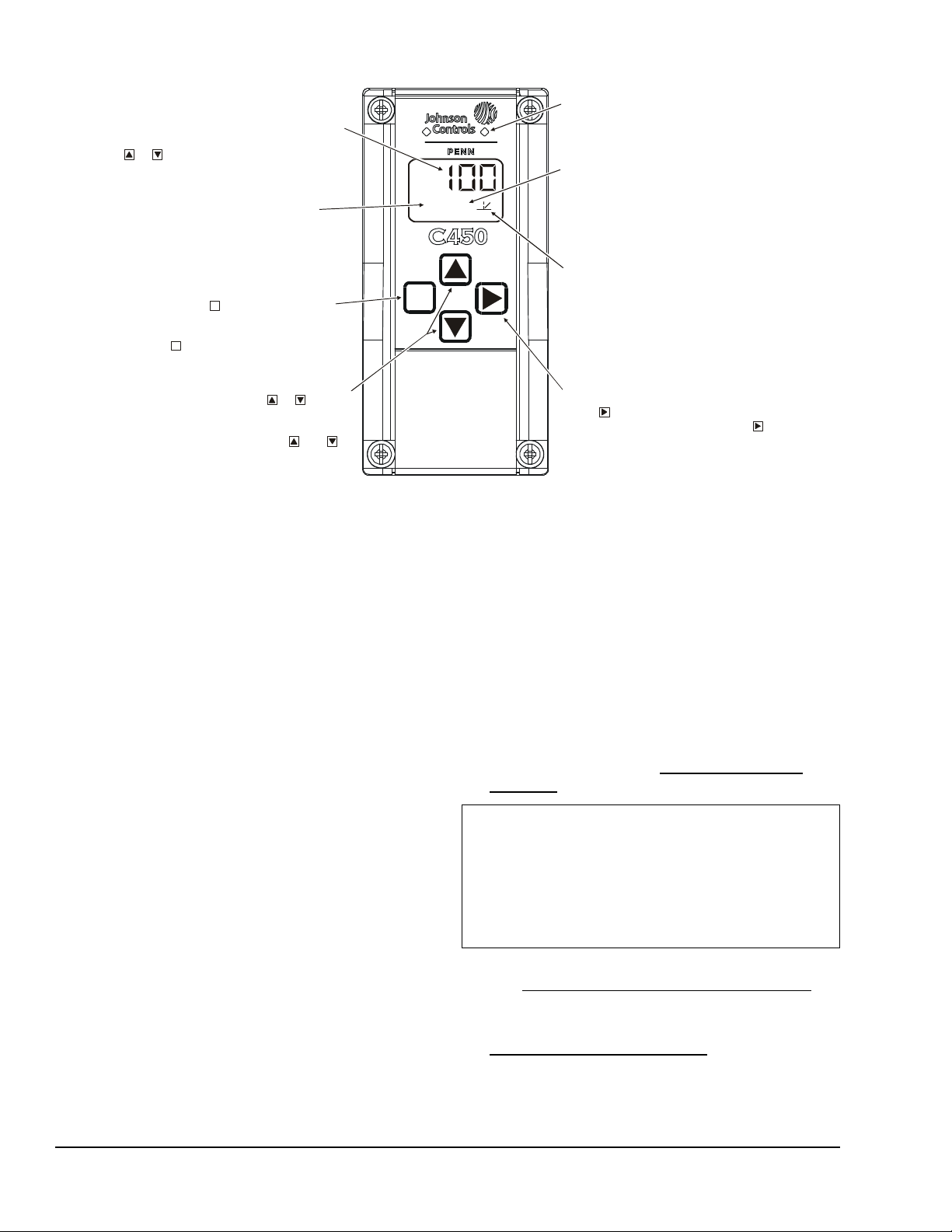
Displays a
Setup Value shown on the screen. Output
Numbers are automatically determined by
in the module assembly. ( = Output 4.)
Control Ramp Icon:
Displays whether an
Analog Output increases or decreases as
the sensor input increases, an d w hether the
output signal strength is at min imum or
maximum when the sensed property is at
Setpoint. The Control Ramp icon displayed
is determined by the Output's SP , EP, OSP,
and OEP setup values.
MENU Button:
Press to move through the
sensor and output setup-start-screens.
When moving through the status or setup
screens, press to return to the status start
screen or setup start screen.
M
M
Status or Setup Identifier:
or
OSP
Displays the
unit of me asurement, output, sensor number,
setup parameter for the displa yed Status or
Setup Value. (Setup Identifier repres ents
% Output Si gnal Strength at Setpoint.)
UP and DOWN Buttons:
Press or to select
a differ ent value for any flashing value in the
Setup Value field. In the Main/Default (Sensor
Status) sc r een, press and hold bot h and
for 5 seconds to access the Setup Start screens.
Status or Setup Value:
or
100
Displays th e current
input stat us, output status setup parameter
value for t he displayed input sensor or output.
select a different Parameter
Value when the value is fl ashing. ( = 100%.)
Press or to
M
osp
4
Light-Emitting Diode (LED):
Green LEDs
associat ed Relay Out put is On or Off.
the (flashing) Setup Value and go to the
next setu p screen.
Figure 4: System 450 Control Module Output Analog LEDs, LCD, Four-Button Touch Pad User Interface
on Relay Control Module and R el ay
Expansion Modules (only) indicates if the
Output (or Sens or ) N um be r:
numerical value tha t identifies the Output
(or Sensor ) associated with the S tatus or
the outputs' physical positions (left to right)
FIG:sys450cntrl_m odul
NEXT Button:
press to scroll through the system status
screens. In a setup screen , press to save
In the Main /D efault screens,
Setup and Adjustments
System 450 Components
A System 450 control system consists of one control
module, one to three control sensors, and one to ten
outputs that provide analog control and/or On/Off
control. Figure 3 shows an example System 450
module assembly with two sensors and three outputs
(two analog outputs and one relay output).
Setting up a Module Assembly
To set up a System 450 module assembly:
1. Determine the controlled conditions, sensor types,
and value ranges required for your application, and
select the appropriate System 450 sensor types.
2. Determine the number and type (relay or analog) of
outputs required to control your application, and
select the appropriate System 450 control module
and expansion modules.
3. Assemble the control and expansion modules,
starting with the control module on the left .
Note: If you use a C450YNN-1 power module, it
must be plugged into the control module. Plug
remaining expansion modules to the right of the
power module.
4. Apply power to the module assembly.
Y ou ca n now set up the module assembly in the control
module UI.
Setting up a Control System in User Interface
System 450 control modules have a back-lit LCD and a
four-button touch pad User Interface (UI) that enable
you to set up all of the inputs (sensors) and outputs in
the module assembly (Figure 4).
Figure 7 provides an example System 450 setup
overview that corresponds to the control system
example shown in Figure 3 and the following setup
examples and procedures.
To set up a control system in the System 450 UI:
1. Build your control system module assembly and
connect it to power. See Setting up a Module
Assembly on page 4.
IMPORTANT: Each time a module assembly is
powered ON, the control module polls all of the
modules to identify output type (relay or analog) and
assigns a sequential output number (1 to 9 [0= 10])
to each output starting with the control module
output on the left. The output numbers identify each
output’s setup screens in the UI. (See Figure 4.)
2. Access the System 450 setup screens in the UI.
See Accessing the System 450 Setup Screens
page 5.
3. Set up the control system inputs in the UI. See
Setting up System 450 Sensors
on
on page 5.
System 450™ Series Control Modules with Analog Outputs Installation Instructions4
Page 5
4. Set up the control system outputs in the UI. See
1
74
2
F
OUT
1
On
64
OUT
3
Setting up System 450 Outputs
IMPORTANT: Do not change the module positions
after a System 450 control system is set up in the
System 450 UI. System 450 control logic is set up in
the UI according to the input Sensor T ypes, the output
types, and the output numbers. Changing modules or
module positions in a module assembly that is
already set up in the UI, can change the output
numbers, output types, and/or the setup values of the
assembly outputs, which will require setting up the
outputs again.
Use the worksheet provided on page 14 to plan and
record the settings for your System 450 control system.
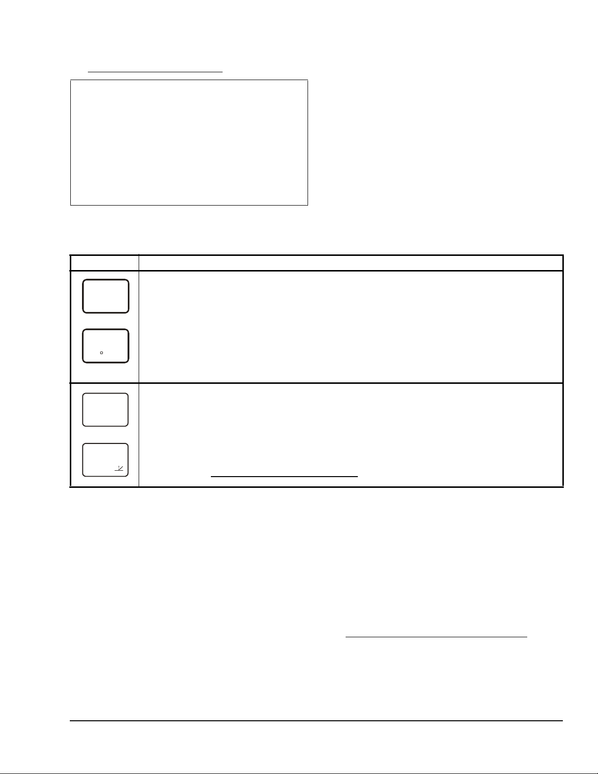
Table 2: System 450 Main Screens and Status Screens Informatio n and Procedures
LCD Screen Name, Description/Function, User Action, and Example
Main (Input Status) Screen: During normal operation, the Main screen automatically scrolls through the
232
PSI
current status at each input sensor in your control system and displays the sensor number, the unit of
measurement, and the sensed condition value. See Figure 7.
Note: Main screens are view-only, selections are not made in Main screens.
Press NEXT repeatedly to scroll through and view the System Status screens for all inputs and
outputs in your control system.
Press and hold both UP and DOWN for 5 seconds to access your control system’s setup screens.
Note: In any system setup screen, you can return to the Main Screens by pressing both UP and DOWN
simultaneously. Also, the UI retu rns to the Main screen after 2 minutes of inactivity in any screen.
Examples show Sensor 1 sensing 232 psi and Sensor 2 sensing 74°F.
System Status Screens: The System Status screens display current status of all inputs and outputs in
your control system. Relay output status screens display output number and relay status (On/Off). Analog
output status screens display output number, signal strength, and control ramp icon. See Figure 7.
Note: System Status screens are view-only, selections are not made in Status screens.
Press NEXT repeatedly to scroll and view the System Status screens for the inputs and outputs in
your control system.
Examples show Output 1 relay is On and Output 3 signal strength is 64% of the total signal strength. The
control ramp icon in the bottom screen example indicates that the Analog Output is set up with SP<EP and
OSP<OEP. (See Setting up an Analog Output (OUTA
on page 7.
Viewing the Main and System Status Screens
After your control system is installed, wired, and setup,
the Main (Input Status) screen appears when you
connect power to your system. During normal
operation, the Main screen displays the current status
of each input (sensor) in your control system. See
Table 2 for more information on the Main screens.
The System Status screens can display an output
status screen for each output in your control system
along with the Input Status screens; in the Main (Input
Status) screen, press NEXT repeatedly to scroll
through and view all of the Output Status screens in
your control system. See Table 2 for more information
on the System Status screens.
#) for information about control ramp icons.)
Accessing the System 450 Setup Screens
You can access the setup screens from the Main
screen. To access the System 450 setup screens:
1. Apply power to your module assembly. After a
startup check, the Main screen appears on the
LCD.
2. In the Main screen, press and hold UP and DOWN
simultaneously for 5 seconds to access the setup
screens and to go to the Sensor Setup Start
screen.
Note: The Sensor Setup Start screen is the first
screen displayed when you access the System 450
setup screens. From the Sensor Setup Start
screen, you can navigate to all of the remaining
setup screens for your control system.
System 450™ Series Control Modules with Analog Outputs Installation Instructions 5
3. Press MENU repeatedly to scroll through the setup
start screens. See Figure 7.
Note: The setup start screens are view-only;
selections cannot be made in setup start screens.
Press NEXT in a Setup Start screen to go to the
sensor or output setup screens.
Setting up System 450 Sensors
You must set up the input sensors for your control
system before you can set up any of outputs. T o set up
the input sensors you must access the setup screens.
See Accessing the System 450 Setup Screens
The Sensor Setup Start screen is the first screen
displayed when you access the system setup screens
in the System 450 UI.
.
Page 6

Table 3 provides information about System 450
Figure 5: Active/Passive Sensor DIP Switch
Block (Set up for Example in Figure 3)
21
ON
(No sens or connected to S3 in Figur e 3.)
S1
S2
S3
SENS
-- -
sensors, Sensor Ty pes, parameter values, and
specified sensor/transducer product code numbers.
Table 4 provides information, procedures, and
examples regarding Sensor Setup screens and setting
up sensors. Figure 7 provides a System 450 UI and
Temperature sensors are passive (2-wire) sensors and
corresponding switches must be set to ON. Humidity
and pressure transducers are active (3-wire) sensors
and corresponding switches must be set to Off. See
Figure 5 for the switch settings for the System 450
example shown in Figure 3.
setup overview example.
Setting Active/Passive Sensor DIP Switches
Before putting your control system into operation, you
must set up each sensor in the system as either
passive or active by positioning the associated switch
3
sys450_dip
Switch 1 sets Sensor (Set to Active/Off)
Switch 2 sets Sensor (Set to Passive/On)
Switch 3 sets Sensor (Set to Active/Off)
(On or Off) on the DIP switch block located below the
sensor terminal block. See Figure 3.
Table 3: System 450 Sensor Types, Setup Values, and Sensor/Transducer Product Codes
Sensor
Type
Unit of Measurement
Value
(Condition/Units)
Effective
Sensing
Range
Range of
Usable
Values
Resolution
Increment
Value
Minimum
Differential
or
Sensor Product
Type Number
1
Proportional
Band
°F °F (Temperature/degrees) -46 to 255 -40 to 250 1 1 A99B-xxx
°C °C (Temperature/degrees) -43 to 124 -40 to 121 0.5 0.5 A99B-xxx
rH % (Humidity/%RH) 1 to 100 10 to 95 1 2 HE67Sx-x
P 05 INWC (Pressure/in. W.C.) 0 to 0.5 0.025 to 0.5 0.005 0.025 DPT-2650-0R5D-AB
P 8 bAR (Pressure/bar) -1 to 8 -1 to 8 0.05 0.1 P499Rxx-401C
P 10 INWC (Pressure/in. W.C.) 0 to 10 0.5 to 10 0.05 0.2 DPT-2650-010D-AB
P 15 bAR (Pressure/bar) -1 to 15 -1 to 15 0.1 0.2 P499Rxx-402C
P 30 bAR (Pressure/bar) 0 to 30 0 to 30 0.1 0.4 P499Rxx-404C
P 50 bAR (Pressure/bar) 0 to 50 0 to 50 0.2 0.4 P499Rxx-405C
P100 PSI (Pressure/psi) 0 to 100 0 to 100 0.5 1 P499Rxx-101C
P200 PSI (Pressure/psi) 0 to 200 0 to 200 1 1 P499Rxx-102C
P500 PSI (Pressure/psi) 0 to 500 90 to 500 1 5 P499Rxx-105C
P750 PSI (Pressure/psi) 0 to 750 150 to 750 2 6 P499Rxx-107C
1. Refer to the System 450 Series Modular Controls Product Bulletin (LIT-12011458), Catalog Page (LIT-1900549), or
Technical Bulletin (LIT-12011459) for complete ordering information for System 450 compatible sensors and transducers.
Table 4: System 450 Sensor Setup Information and Procedures
LCD Screen Name, Description/Function, User Action, and Example
Sensor Setup Start Screen: The Sensor Setup Start screen is the first screen displayed when you
access the System 450 setup screens. From the Sensor Setup Start screen you can navigate to the
Output Setup Start screens or the Sensor Setup screens. See Figure 7.
Note: You must setup the input sensors before you can setup the control system outputs. The Sensor
Setup Start screen is view-only, selections are not made in setup start screens.
Press MENU (repeatedly) to scroll through the Output Setup Start screens. (See Setting up a
Relay Output (OUTR#) and Setting up an Analog Output (OUTA#) for information and procedures on
setting up outputs.)
1. Press NEXT to go to the first Sensor Type Selection screen (Sn-1) and begin setting up the
sensors in your control system.
Example shows the Sensors Setup Start screen with four flashing dashes.
System 450™ Series Control Modules with Analog Outputs Installation Instructions6
Page 7

Table 4: System 450 Sensor Setup Information and Procedures (Continued)
P500
Sn-1
°F
Sn-2
--
Sn-3
-3
OFFS
SENS
-- -
LCD Screen Name, Description/Function, User Action, and Example
Sensor Type Selection Screens: The Sensor Type you select for an input sensor automatically
determines the setup parameters and values for each output that is set up to reference that sensor. See
Table 3 for information about System 45 0 sensors/transducers, Sensor Types, condition type, units of
measurement, minimum differential or proportional band, setup values, value ranges, and product code
numbers.
Note: For an output to operate properly, the selected Sensor Type must match the sensor/transducer
model wired to the control module, and the sensor/transducer must be wired to the proper control module
input terminals.
2. In the Sn-1 Sensor Type Selection screen, press UP or DOWN to select the desired Sensor
Type. Press NEXT to save your selection and go to the Sn-2 Sensor Type Selection screen.
3. In the Sn-2 Sensor Type Selection screen, press UP or DOWN to select the desired Sensor
Type. Press NEXT to save your selection and go to the Sn-3 Sensor Type Selection screen.
Note: If your control system does not use three input sensors, simply press NEXT while the two dashes
are flashing in a Sensor Type Selection screen to save no Sensor Type and go to the next setup screen.
4. In the Sn-3 Sensor Type Selection screen, press UP or DOWN to select the desired Sensor
Type. Press NEXT to save your selection and either:
• go to the Temperature Offset Setup screen for the first temperature sensor in your system.
• return to the Sensor Setup-Start Screen, if your control system has no temperature sensors.
Examples show Sensor 1 with the P500 Sensor Type selected; Sensor 2, with the °F Sensor Type
selected; and Sensor 3, with the no Sensor Type selected.
T emperature Offset Selection Screens: Select a temperature offset for the temperature inputs (only) in
your control system.
2
Sensor Type °F enables an offset of +/- 5°F in 1 degree increments.
Sensor Type °C enables an offset of +/- 2.5°C in 0.5 degree increments.
Note: The temperature offset changes the displayed temperature value by the selected offset value.
5. Press UP or DOWN to select the desired temperature offset value. Press NEXT:
• to go to the next Temperature Offset Selection screen and repeat this step (if required).
• to return to the Sensors Setup-Start Screen.
Example shows -3 (flashing) is the selected temperature offset value for Sensor 2, thus a sensed
temperature of 75°F at Sensor 2 is displayed as 72°F.
Sensors Setup Start Screen: The Sensor Setup screens return to the Sensor Setup Start screen.
After the sensors are set up for your control system, you can:
• Press MENU to scroll through the Output Setup Start screens and begin setting up your
system outputs. (See Setting up a Relay Output (OUTR
for more information and procedures.)
• Press UP and DOWN simultaneously and hold for 5 seconds to return to the Main screens.
Example shows Input Sensors Setup-Start screen with four flashing dashes.
#) and Setting up an Analog Output (OUTA#)
Setting up System 450 Outputs
After you build and connect power to your control
system module assembly, the output numbers and
output types for your control system are auto m at ica lly
assigned in the UI.
Note: You must set up the input sensors for your
control system before you can set up the outputs.
To set up System 450 outputs in the UI:
1. Access the System 450 setup screens, the Sensor
Setup Start screen (SENS) appears. (See
Accessing the System 450 Setup Screens
System 450™ Series Control Modules with Analog Outputs Installation Instructions 7
.)
2. In the Sensor Setup Start screen (SENS), press
MENU repeatedly to scroll through and select the
desired Output Setup Start screen. The Output
Setup Start screen indicates the output number
and the output type for the selected output.
For Relay Outputs, see Setting up a Relay Output
(OUTR#) and Table 5 for setup information and
procedures.
For Analog Outputs, see Setting up an Analog Output
(OUTA#) and Table 7 for setup information and
procedures.
Page 8

Setting up a Relay Output (OUTR#)
OUTR
1
-- -
SENS
SENS
N
1
78
1
T
1
0
T
1
120
1
OFF
Relay outputs provide On/Off contro l for the equipment
in your application based on input from the sensor the
output is set up to reference. See Table 5 for relay
output setup information and procedures.
Table 5: System 450 Relay Output Setup Screen Information, and User Actions
LCD Screen Name, Description/Function, User Action, and Example
Relay Output Setup Star t Scr e en : Output number and the output type (relay or analog) are
automatically assigned when you connect power to your control system’s module assembly.
Note: You must set up the system’s sensors before you can set up the outputs.
1. Press NEXT to go to this output’s Sensor Selection screen.
Example shows the Relay Output Setup-Start screen for Output 1.
Sensor Selection Screen: The sensor you select here determines this output’s setup parameters and
--
Sn-2
O
OFF
ON
OFF
SNF
values, including condition type, unit of measurement, minimum differential, default setup values, and
setup value ranges for several of the remaining output setup screens. If a sensor is not selected here, this
output’s remaining setup screens do not appear. If a sensor is already selected for this output, the Sensor
Selection screen does not appear here, instead the Relay ON Selection screen appears.
Note: Y ou must select a sensor in this Sensor Selection screen and the selected sensor must be already
set up in the System 450 UI. (See Setting up System 450 Sensors
2. Press UP or DOWN to select the Sensor (Sn-1, Sn-2, or Sn-3) that this output references. Press
NEXT to save your sensor selection and go to the Relay ON Selection Screen.
Example shows input Sensor 2 selected for Output 1.
Relay ON Selection Screen: Select the value at which the relay turns On. Relay ON is defined as relay
LED On/Lit, relay contacts NO to C are closed, and NC to C contacts are open.
Note: The value ranges and minimum differential are determined by the Sensor Type selected for the
sensor that this output references and are enforced in the Relay ON and Relay OFF Selection screens.
3. Press UP or DOWN to select the value at which the output relay turns On. Press NEXT to save
your selection and go to Relay OFF Selection Screen.
Example shows an ON value of 78 (°F) selected for Relay Output 1.
Relay OFF Selection Screen: Select the value at which the relay turns Off. Relay OFF is defined as
relay LED Off, relay contacts NC to C are closed, and NO to C contacts are open.
Note: The value ranges and minimum differential are determined by the Sensor Type selected for the
sensor that this output references and are enforced in the Relay ON and Relay OFF Selection screens.
4. Press UP or DOWN to select the value at which output relay turns Off. Press NEXT to save
your selection and go to Minimum Relay ON TIme Selection Screen.
Example shows an OFF value of 75 (°F) selected for Relay Output 1.
Minimum Relay ON Time Selection Screen: Minimum ON Time range is 0 to 300 seconds.
5. Press UP or DOWN to select the minimum time that the output relay remains On after reaching
the Relay ON value. Press NEXT to save your selection and go to the Minimum Relay OFF Time
Selection Screen.
Example shows 0 (zero) seconds selected for the minimum ON-Time for Output 1.
Minimum Relay OFF Time Selection Screen: Minimum OFF Time range is 0 to 300 seconds.
6. Press UP or DOWN to select the minimum time that this output relay remains Off after reaching
the Relay OFF value. Press NEXT to save your selection and go to the Sensor Failu re Mode
Selection screen.
Example shows 120 seconds selected for the minimum OFF-Time for Output 1.
Sensor Failure Mode Selection Screen: Select this output’s mode of operation if the referenced sensor
or sensor wiring fails. The output operates in the selected mode until the failure is remedied.
Sensor Failure mode selections for Relay Outputs include:
• ON output relay remains On during sensor failure.
• OFF output relay remains Off during sensor failure.
7. Press UP or DOWN to select this output mode of operation if the sensor or sensor wiring fails.
Press NEXT to save your sensor failure mode selection and go to the Edit Sensor Screen.
Example shows OFF sensor failure mode selected for Output 1. This output relay is Off if the referenced
sensor or sensor wiring fails.
.)
System 450™ Series Control Modules with Analog Outputs Installation Instructions8
Page 9

Table 5: System 450 Relay Output Setup Screen Information, and User Actions (Continued)
SENS
OUTR
1
-- -
0%
100%
Less Greater
65
°F
10%
70
°F
SP > EP
SP = 70 ( )
EP = 65 ( )
OSP = 10 (%)
°F
°F
OSP < OEP
OEP
Band
Fig:sys450_cntrl_rmp_exmpl
Figure 6: Control Ramp Example for a Typical
Heating Application (SP > EP and OSP < OEP)
LCD Screen Name, Description/Function, User Action, and Example
Edit Sensor Screen: This screen displays the sensor that this output currently references. Typically, no
Sn-2
action is taken in this screen. But if you need to change the sensor that this output references, you can
select a different sensor for this output in this screen.
Note: Changing the sensor that an output references to a sensor with a different Sensor Type changes
the default setup values for the output, and requires setting up the output again.
8. To change this output’s sensor, Press UP or DOWN to select the sensor that this output will
reference. After you select a different sensor for this output, press NEXT to return to the Relay
ON Selection screen (Step 3 above) and repeat the output relay setup procedure for this output
and the new Sensor Type values associated with the new sensor selection.
If you do not need to change this output’s sensor, simply press NEXT to save the current
sensor selection and return to the Relay Output Setup Start screen.
This Relay Output is now set up in the System 450 UI.
Example shows input Sensor 2 selected for Output 1 (Output 1 references Sensor 2).
Relay Output Setup Start Screen
After you have set up this Relay Output, you can go to another Output Setup Start screen, the Sensor
Setup Start screen, or return to the Main screens.
9. Press MENU to scroll through the remaining Output Setup Start screens and return to the
Sensor Setup Start screen, or press UP and DOWN simultaneously and hold for 5 seconds to
return to the System 450 Main screens.
Example shows the Relay Output Setup-Start screen for Output 1.
Setting up an Analog Output (OUTA#)
Analog outputs provide an auto-selecting analog sign al
that is proportional to the sensed input condition. The
analog output circuit senses the impedance and
automatically selects 0-10 VDC or 4-20 mA operation.
The control action between the input signal and the
output signal can be set up four different ways,
depending on the values selected for the Setpoint (SP),
End Point (EP), %Output Signal Strength at Setpoint
(OSP), and %Output Signal Strength at End Point
(OEP). The LCD displays different Control Ramp icons
for the four control actions.
Figure 6 shows an example of the analog output setup
values and the resulting output signal in a typical sp ace
heating application (SP > EP and OSP < OEP).
Proportional
EP
SP
System Output
OSP
OEP = 10 0 ( % )
Table 6 shows the four Control Ramp icons and the
associated analog output setup value relationships.
Table 6: Analog Output Control Ramp Icons
Control Ramp
Displayed on
LCD
Analog
Output Value
Relationships
SP < EP
OSP < OEP
SP > EP
OSP < OEP
SP > EP
OSP > OEP
SP < EP
OSP > OEP
Output Signal
Strength at
Setpoint
Minimum
Minimum
Maximum
Maximum
See Table 7 for analog output setup information and
procedures.
Condition Value
System 450™ Series Control Modules with Analog Outputs Installation Instructions 9
Page 10

Table 7: System 450 Analog Output Setup Screens Information (Part 1 of 2)
OUTA
3
-- -
SENS
3
Sn-1
3
200
3
250
OSP
3
10
OEP
3
90
I-C
3
0
LCD Screen Name, Description/Function, User Action, Example
Analog Output Setup Start Screen: Output number and the output type (relay or analog) are
automatically assigned when you connect power to your control system’s module assembly.
Note: You must set up the system’s sensors before you can set up the outputs.
1. Press NEXT to go to this output’s Sensor Selection screen.
Example shows the Analog Output Setup-Start screen for Output 3.
Sensor Selection Screen: The Sensor you select here determines this output’s setup parameters and
values, including condition type, unit of measurement, minimum proportional band, default setup values,
and setup value ranges for several of the remaining output setup screens. If a sensor is not selected here,
this output’s remaining setup screens do not appear. If a sensor is already selected for this output, the
Sensor Selection screen does not appear here, instead the Setpoint Selection screen appears.
Note: You must select a sensor in this Sensor Selection screen and the selected sensor must be already
SP
EP
set up in the System 450 UI. (See Setting up System 450 Sensors
2. Press UP or DOWN to select the Sensor (Sn-1, Sn-2, or Sn-3) that this output references. Press
NEXT to save your sensor selection and go to the Setpoint Selection screen.
Example shows input Sensor 1 (Sn-1) selected for Output 3.
Setpoint Selection Screen: Setpoint is the target value that the controlled system drives towards and
along with End Point, defines this output’s proportional band.
Note: An output’s minimum proportional band (between Setpoint and End Point) is automatically
enforced in the output’s Setpoint and End Point Selection screens.
3. Press UP or DOWN to select this output’s Setpoint value. Press NEXT to save your Setpoint
value selection and go to the End Point Selection screen.
Example shows a Setpoint of 200 (psi) selected for Output 3.
End Point Selection Screen: End Point is the (condition) value that the controlled system drives away
from (towards Setpoint) and, along with Setpoint, defines this output’s proportional band.
Note: An output’s proportional band (between Setpoint and End Point) is automatically enforced in the
output’s Setpoint and End Point Selection screens.
4. Press UP or DOWN to select this output’s End Point value. Press NEXT to save your End Point
value selection and go to the %Output Signal Strength at Setpoint Selection screen.
Example shows a End Point of 250 (psi) selected for Output 3.
Output Signal Strength at Setpoint Selection Screen: Select the strength of the signal that this output
generates when the sensed condition is at the Setpoint value. The signal strength range is 0 to 100 (%).
5. Press UP or DOWN to select this output’s %Output Signal Strength at Setpoint value. Press
NEXT to save your selection and go to the %Output Signal Strength at End Point Selection
screen.
Example shows Analog Output 3 is setup to generate 10% of the total signal strength when the input is at
the Setpoint value (= 1 V or 5.6 mA).
Output Signal Strength at End Point Selection Screen: Select the strength of the signal that this output
generates when the sensed condition is at the End Point value. The signal strength range is
0 to 100 (%).
6. Press UP or DOWN to select this output’s %Output Signal Strength at End Point value. Press
NEXT to save your selection and go to the Integration Constant Selection screen.
Example shows Output 3 is set up to generate 90% of the total signal strength when the input is at the End
Point value (= 9 V or 18.4 mA).
Integration Constant Selection Screen: An integration constant allows you to set up proportional plus
integral control for this analog output. proportional plus integral control can drive the load closer to
Setpoint than proportional only control.
Note: Initially, you should select the I-C value of 0 (zero) for no integration constant. Refer to the System
450 Series Technical Bulletin (LIT-12011459) for more information on proportional plus integral control
and setting an integration constant in the System 450 UI.
7. Press UP or DOWN to select this output’s Integration Constant for proportional plus integral
control. Press NEXT to save your selection and go to the Sensor Failure Mode Selection
screen.
Example shows an Integration Constant of 0 (zero) selected for Output 3.
.)
System 450™ Series Control Modules with Analog Outputs Installation Instructions10
Page 11

Table 7: System 450 Analog Output Setup Screens Information (Part 2 of 2)
SNF
3
OFF
3
Sn-1
LCD Screen Name, Description/Function, User Action, Example
Sensor Failure Mode Selection Screen:
8. Press UP or DOWN to select this output’s mode of operation if the sensor or sensor wiring
fails. Press NEXT to save your selection and go to the Edit Sensor Selection screen.
Y ou can select this output’s mode of operation in the event of a sensor or sensor wiring failure. The output
operates in the selected mode until the failure is fixed. Sensor Failure Mode selections for Analog Outputs
include:
• ON - output generates maximum signal strength during sensor failure.
• OFF- output generates minimum signal strength during sensor failure.
Example shows the OFF Sensor Failure Mode selected for Output 3.
Edit Sensor Selection Screen: Press Up or Down to change the sensor that this output references (only
if required), then press Next to go to this output’s setup start screen.
Note: Changing the sensor that an output references to a sensor with a different Sensor Type changes
SENS
the default setup values for the output, and requires setting up the output again.
Example shows input Sensor 1 selected for Output 3.
Technical Specifications
C450CxN-1 (Part 1 of 2)
Product C450CxN-1: System 450 Control Module models are sensing controls and operating
controls with LCD, four-button touch pad, and analog output.
C450CPN-1: Control Module with One Analog Output
C450CQN-1: Control Module with Two Analog Outputs
Supply Power C450YNN-1 Power Supply Module or
24 (20-30) VAC Safety Extra-Low Voltage (SELV) (Europe) Class 2 (North America)
50/60 Hz, 10 VA minimum
Ambient Operating Conditions Temperature: -40 to 66°C (-40 to 150°F) when using 0-10 VDC outputs;
-40 to 40°C (-40 to 104°F) when using 4-20 mA outputs
Humidity: Up to 95% RH noncondensing; Maximum Dew Point 29°C (85°F)
Ambient Shipping and Storage
Conditions
Input Signal 0-5 VDC; 1035 ohms at 25°C (77°F) for an A99 PTC Temperature Sensor
Analog Output Voltage Mode (0–10 VDC):
Analog Input Accuracy Resolution: 14 bit
Control Construction Independently-mounted control, surface mounted with Lexan® 950 enclosure suitable
Dimensions (H x W x D) 127 x 61 x 61 mm (5 x 2-3/8 x 2-3/8 in.)
Weight C450CPN-1: 195 g (0.43 lb)
Temperature: -40 to 80°C (-40 to 176°F)
Humidity: Up to 95% RH noncondensing; Maximum Dew Point 29°C (85°F)
10 VDC maximum output voltage
10 mA maximum output current
Requires an external load of 1,000 ohm or more
Note: The AO operates in Voltage Mode when connected to devices with
impedances greater than 1,000 ohm. Devices that drop below 1,000 ohm may not
operate as intended for Voltage Mode applications.
Current Mode (4–20 mA):
Requires an external load between 0–300 ohm
Note: The AO operates in Current Mode when connected to devices with
impedances greater than 1,000 ohm. Devices that drop below 1,000 ohm may not
operate as intended for Current Mode applications.
for DIN rail mounting or direct mounting to a hard, even surface.
C450CQN-1: 195 g (0.43 lb)
System 450™ Series Control Modules with Analog Outputs Installation Instructions 11
Page 12

C450CxN-1 (Part 2 of 2)
Compliance North America: cULus Listed; UL 60730, File E27734, Vol. 1; FCC Compliant to
CFR47, Part 15, Subpart B, Class B
Industry Canada (IC) Compliant to Canadian ICES-003, Class B limits
Europe: Mark: CE Compliant; Low Voltage Directive (2006/95/EC); EMC Directive
(2004/108/EC); RoHS Directive (2002/95/EC); WEEE Directive (2002/96/EC)
Australia: Mark: C-Tick Compliant (N1813)
The performance specifications are nominal and conform to acceptable industry standards. For application at conditions beyond these
specifications, consult Johnson Controls Application Engineering at (414) 524-5535. Johnson Controls, Inc. shall not be liable for damages
resulting from misapplication or misuse of its products.
United States Emissions Compliance
This equipment has been tested and found to comply with the limits for a Class B digital device, pursuant to Part 15 of the FCC Rules. These
limits are designed to provide reasonable protection against harmful interference in a residential installation. This equipment generates, uses
and can radiate radio frequency energy and, if not installed and used in accordance with the instructions, may cause harmful interference to
radio communications. However, there is no guarantee that interference will not occur in a particular installation. If this equipment does cause
harmful interference to radio or television reception, which can be determined by turning the equipment off and on, the user is encouraged to try
to correct the interference by one or more of the following measures:
- Reorient or relocate the receiving antenna.
- Increase the separation between the equipment and receiver.
- Connect the equipment into an outlet on a circuit different from that to which the receiver is connected.
- Consult the dealer or an experienced radio/TV technician for help.
Canadian Emissions Compliance
This Class (B) digital apparatus meets all the requirements of the Canadian Interference-Causing Equipment Regulations.
Cet appareil numérique de la Classe (B) respecte toutes les exigences du Règlement sur le matériel brouilleur du Canada.
System 450™ Series Control Modules with Analog Outputs Installation Instructions12
Page 13

Figure 7: System 450 Status Screens, Setup Screens, and Menu Flow Example
Relay Output
Setup Start
OUTR
1
-- -
Sensor 2 S elected.
(Displayed only when a
Sensor is selected.)
not
Up to
ten
Outputs
can be
connected
and
set up.
M
Relay
Output
1
OUTA
3
OutputAnalog
Setup Start
Analog
Output
3
Select Relay ON
Value
ON
1
78
Relay
at ºF
1ON
78
OFF
1
Select Relay OFF
Value
Relay
at ºF
1OFF
75
Select Mini
Relay ON
ONT
1
0
Relay
Seconds
(Minimum)
1ON
0
)
Select
Setpoin t Value
Prop. Band
SP
3
200
Analog Output
Prop. Band
Setpoint psi
3
200
Sele
End
Ana
End
FIG:menu_flw_chrt
M
232
PSI
1
Main Screen
Sensor 2 S t at us
74
2
F
Sensor 1 St at us
Up to ten Outp
can be set up
displayed.
Relay Output 2
Status
OFF
OUT
2
Output 2 Relay
OFF
Relay Output 1
Status
OUT
1
Output 1 Relay
On
Analog Output 3
Status
64
OUT
3
Output 3 Signal
at % of Range
64
Control Sensor 3
Status
----
3
Control Sens or 3
Not Set Up
Control Sensor 2
Status
74ºF
74
2
F
232
PSI
1
Control Sensor 1
Status
232 psi
Sensor Setup
Screens
System Status
Screens
Main Screens
(Sensor Status)
Relay Output
Setup Screens
Analog O utput
Setup Screens
M
Press and hold +
for 5 seconds to go to
the Setup Start screens.
Press to scroll through
Sensor Status screens and
Output S tatus screens.
Select
Control Se nsor
Sn-2
SENS
SENS
Sensor Type
Setup Start
-- -
Select Sensor 2
Type
°F
Sensor Type
(-40 to 250ºF)
ºF
Select Sensor 3
Type
--
No
Sensor Type
Selected
Select Sensor 1
Type
P500
Sn-1
Sn-2 Sn-3
3
Select
Control Sensor
SENS
3
Sensor 1 Selected
(Displayed only
when a Sensor
is selected.)
not
Sn-1
)
Select
Te mperature (on
Offset Degree
-3
OFFS
During norm al operation, the display autom at i c
for all sensor s s et up in th e UI.
After a 2 min ut e pause in any setup or stat us s
Main (Sen sor Status) screens.
Press in any Setup screen to go to the asso
Press + simultaneously in any Setup Star
M
On
2
M
-- -
Output 2
Setup Start
Screen
3
Edit
Control Sensor
1
1
Sn-2
2
SENS
Controls Relay
Sensor (Sn-2
1
1OFF
Failure Mode
Select Sensor
uts
and
Edit
Contr ol Sensor
OFF
Relay
Failure Mode
ally scro lls through the Sensor S t at us screens
Main Screen
ciated Setup Start screen.
creen (below), the display retur ns to the
t screen to return to the Main screen.
ly)
s
Select Sensor
Select Minimum
Relay OFF Time
mum
Time
SNF
1
120
OFFT
if Sensor 2 Fails
1OFF
Seconds
(Minimum
120
Relay
Constant Value
Select Integration
at End Point
Signal Value
Select % Output
at Setpoint
Signal Value
Select % Output
Point Value
ct Prop. Band
1
Sn-1
SENS
Sensor (Sn-1)
3
3
OFF
SNF
Analog Output
3
0
3
I-C
Analog Output
90
3
90
OEP
Output Signal %
10
3
10
OSP
Output S ig nal %
3
3
250
EP
log Output Prop. Band
Controls
if
OFF
Integration
No
of Range at
of Range at
Analog Out put
Sensor 1 Fails
Constant
Value
End Point
Value
Setpoint
250
Point psi
System 450™ Series Control Modules with Analog Outputs Installation Instructions 13
Page 14

System 450™ Series Control Modules with Analog Outputs Installation Instructions14
Page 15

System 450™ Series Control Modules with Analog Outputs Installation Instructions 15
Page 16

System 450™ Series Control Modules with Analog Outputs Installation Instructions16
Metasys® and Johnson Controls® are registered trademarks of Johnson Controls, Inc.
All other marks herein are the marks of their respective owners. © 2009 Johnson Controls, Inc.
Building Efficiency
507 E. Michigan Street, Milwaukee, WI 53202
Published in U.S.A. www.johnsoncontrols.com
 Loading...