

Page 1
FANs 930, 930.5, 125
Product/Technical Bulletin Y350R
Issue Date 0598
System 350
The Y350R is a rectified Class 2, 24 VAC power
supply module designed specific ally for use with
System 350™ Modular Control Systems.
As with all System 350 products, the Y350R is housed
in a compact NEMA 1, high-impact plastic enclosure.
The modular design provides eas y , plug-in
connections for quic k ins tallation and future
expandability.
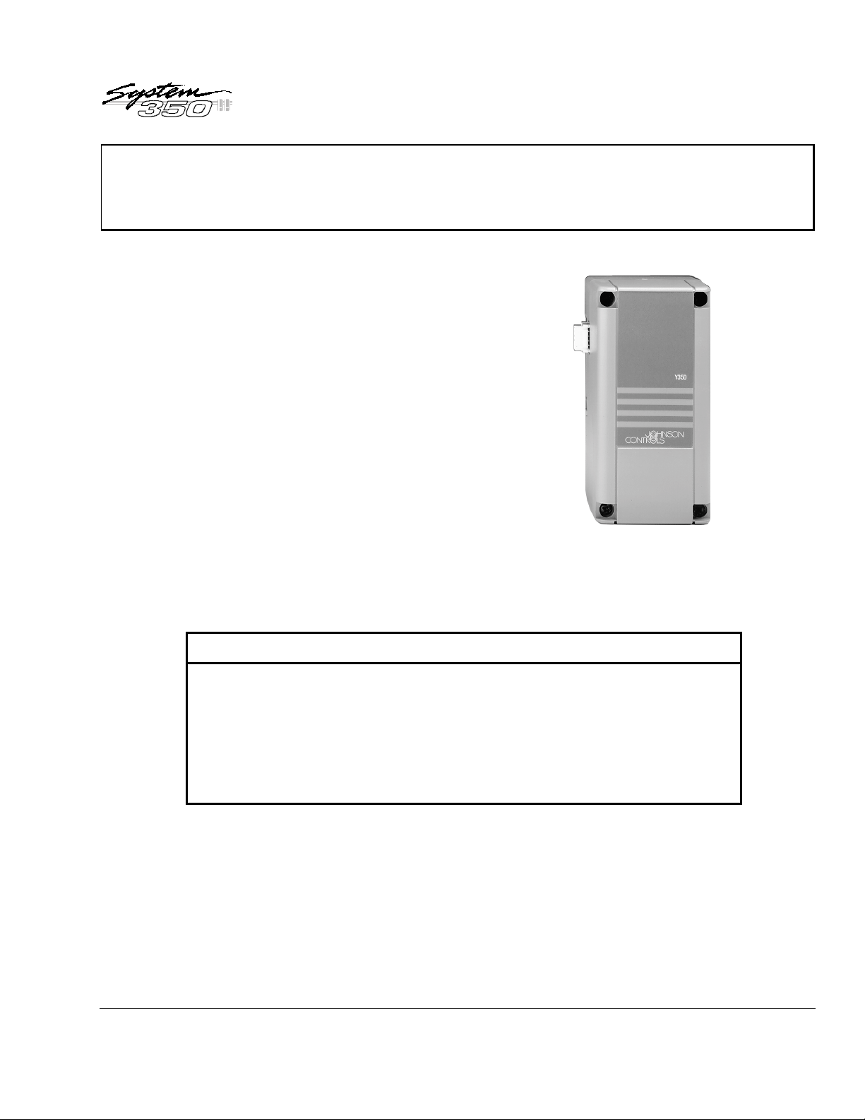
Y350R Power M odule
Figure 1: Y350R Power Module
❑
Modular De s ign
❑
Plug-in Connect or s a nd
35 mm D IN R a il M ounting
❑
Accepts Input Voltages of
120 or 240 VAC, 50/60 Hz
© 1998 Johnson Controls, Inc.
Part No. 24-7664-214, Rev. D
Code No. LIT-930090
Features and Benefits
Enables stage, display, and power modules to be
purchased and installed as necessary
Eliminates wiring between modules and reduces
installation costs
Reduces inventory by encompassing the primary
voltage requirements
1
Page 2
pplication
A
The Y350R Power Module provides the power
necessary to operate all System 350 controls and
add-on modules. For system capabilities, see T able 1.
Table 1: Maximum Number of A dd-on
Modules when Powered by a Y350R
Control
Module
A350A
A350B
A350E
A350P
A350R
A350S
W351A
W351P
P352A
P352P
R353
Stage Module
9 S350A’s or S350C’s
6 S350A’s or S350C’s with
1 S350P
4 S350A’s or S350C’s with
2 S350P’s
4 S350A’s or S350C’s
2 S350A’s or S350C’s with
1 S350P
9 S350A’s or S350C’s
6 S350A’s or S350C’s with
1 S350P
4 S350A’s or S350C’s with
2 S350P’s
5 S351’s 1 D351
4 S351’s 1 D351
5 S352’s 1 D352
No additional stages available 1 D352
5 S353’s No
All System 350 add-on modules snap on to a DIN rail
and plug into the control and to each other via 5-pin
connectors. A dd- on m odules c an be ar r anged in any
order and there is no wiring requir ed to interconnect
the System 350 components.
Display
Module
1 D350
1 D350
2 D350
display
available
IMPORTA NT: All Series Y350R Power Modules
are designed for use only in
conjunction with operat ing
controls. W her e an oper ating
control failure would res ult in
personal injury and/or loss of
property, it is the responsibility of
the installer to add dev ic es
(safety, lim it controls) t hat protect
against, or systems (alarm,
supervisory systems) that warn
of, control failure.
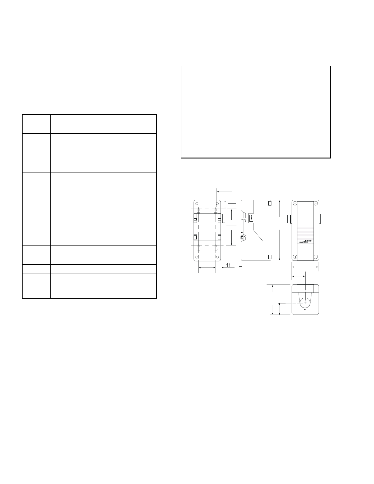
imensions
D
3.68
Mounting Slot (4)
for No . 6 Sc rews
0.145
13
0.5
61
2.40
127
5.00
21.6
0.85
Cond uit
Hole
31
1.20
Y350
61
2.40
22
0.875
40
1.56
75
2.94
0.42
DIN Rail
Mount
Figure 2: Y350R Dimensions, mm /in.
peration
O
The Y350R operates f r om 240 V A C or 120 V A C
power. A 24 VAC, Clas s 2, step-down trans former
brings the voltage to a level which the Syst em 350
modules will accept. There are no adjustment s for the
power module.
2 Y350R Power Module Product/Technical Bu l l e ti n
nstallation and Wir ing
I
The Y350R case has provis ions for mounting to a
standard 35 mm DIN r ail, or can be mounted using t he
four key slot m ounting holes located in the rear of the
case.
Mount System 350 modules in any convenient location
using either the DIN r ail m ounts or the mounting holes
located on the back of the control case. The
components are not pos ition sensitive, but should be
mounted so they can be eas ily wir ed and adjus ted.
Page 3

heckout Procedure
C
IMPORTA NT: All wiring must be inst alled to
conform to t he National Electrical
Code and local regulations.
1. Secure the module to the DIN rail, wall, or panel.
!
WARNING: Electrical S hock Hazard.
Disconnect power supply before
modules are interconnected and
wiring connections are made to
avoid possible electrical s hoc k or
damage to the equipment.
2. Connect input wiring to the Y350R power module.
Strip approximat ely 3/8 inch from the wir e
insulation, insert the wire under each terminal
screw, and tight en. (See Figure 3.)
Note: If conduit is used when installing Syst em 350
components, be sur e to connect the hub t o the
conduit before the hub is s ec ur ed to the
enclosure.
Before applying power, m ak e s ur e ins tallation and
wiring connections are acc or ding to job specifications .
After necess ar y adjus tments and electr ic al
connections have been made, put the syst em in
operation and observe at leas t three complete
operating cycles before leaving the installation.
roubleshooting
T
If the control syst em does not function properly and
the Y350R is suspect , proceed as follows:
1. Connect a Digital Voltmeter (DVM) between the
24V (+) and COM (-) terminals located on the
control module’s left-side connector. (Terminal
designations are marked on the control module.)
2. Select DC volts on the DVM and verify that the
voltage is between 16 and 38 VDC. If the DVM
reading is within range, t he Y 350R is functioning
properly.
Note: Consult the
appropriate control bulletin for a complete
system troubleshooting procedure.
Troubleshooting
section of the
Module
Conn ector
240 VAC CO M 120 VA C
P owe r Input Terminals
Figure 3: Inte r ior of the Y 350R Power
Module
rdering Information
O
Table 2: Product Availa ble
Item Product Code Description
Power Module
Y350R-1C Rectified, Class 2, 24 VAC Power Supply
Module
Conn ector
3. If the DVM r eading is not within the indicated
voltage range, check wir ing and c or r ec t if
necessary. I f the wiring is correc t and the reading
remains out of range, replace the Y350R.
epairs and Replacement
R
Field repairs or calibration must not be made.
Replacement modules are available through the
nearest Johnson Contr ols r epr es entative. (See Table
2.)
Y350R Power Module Product/Technical Bu l l e ti n 3
Page 4

pecifications
S
Product
Input Voltage
Output Vo lta g e
Material
Ambient Temperature
Ambient Humidity
Mounting
Agency Listing
The performance specifications are nominal and conform to acceptable industry standards. For application at conditions beyond these specifications,
consult the local Johnson Controls office. Johnson Controls, Inc. shall not be liable for damages resulting from misapplication or misuse of its products.
Y350R Power Module
120/240 VAC, 50/60 Hz
Rectified 24 VAC, 10 VA, Class 2
Case and cover: NEMA 1 high-impact plastic
Operating: -34 to 66°C (-30 to 150°F)
Shipping: -40 to 85°C (-40 to 185°F)
0 to 95% RH non-condensing
Wall or DIN rail
UL Guide No. XAPX, File E27734
CUL Guide No. XAPX7, File E27734
CSA Class No. 4813 02, File LR948
Controls Group
507 E. Michigan Street
P.O. Box 423
Milwaukee, WI 53201 Printed in U.S.A.
4 Y350R Power Module Product/Technical Bu l l e ti n
 Loading...