

Page 1
Features and Benefits
FANs 930, 930.5, 125, 121
Product/Technical Bulletin A350P
Issue Date 0414
System 350
TM
A350P Electronic Proportional Plus Integral
Temperature Control
The A350P is an electronic, proportional plus int egral
temperature control with analog 0 to 10 VDC and
0 to 20 mA outputs. The control is equipped with
three user-selectable time integration constants and
an adjustable throttling range of 2 to 30F° (1 to 17C°).
Two models cover a setpoint range of -30 to 130°F
(-35 to 55°C) and 90 to 250°F (32 to 121°C).
As are all System 350™ products, the A350P control
is housed in a NEMA 1, high-impact plastic enclosure.
The modular design provides easy, plug-together
connections for quick installation and fut ure
expandability.
Modular Design Enables stage, display, and power modul es to
be purchased and installed a s needed
Plug-Together Connectors
and 35 mm DIN Rail
Mounting
Eliminates wiring between m odules, whi ch
reduces installation costs
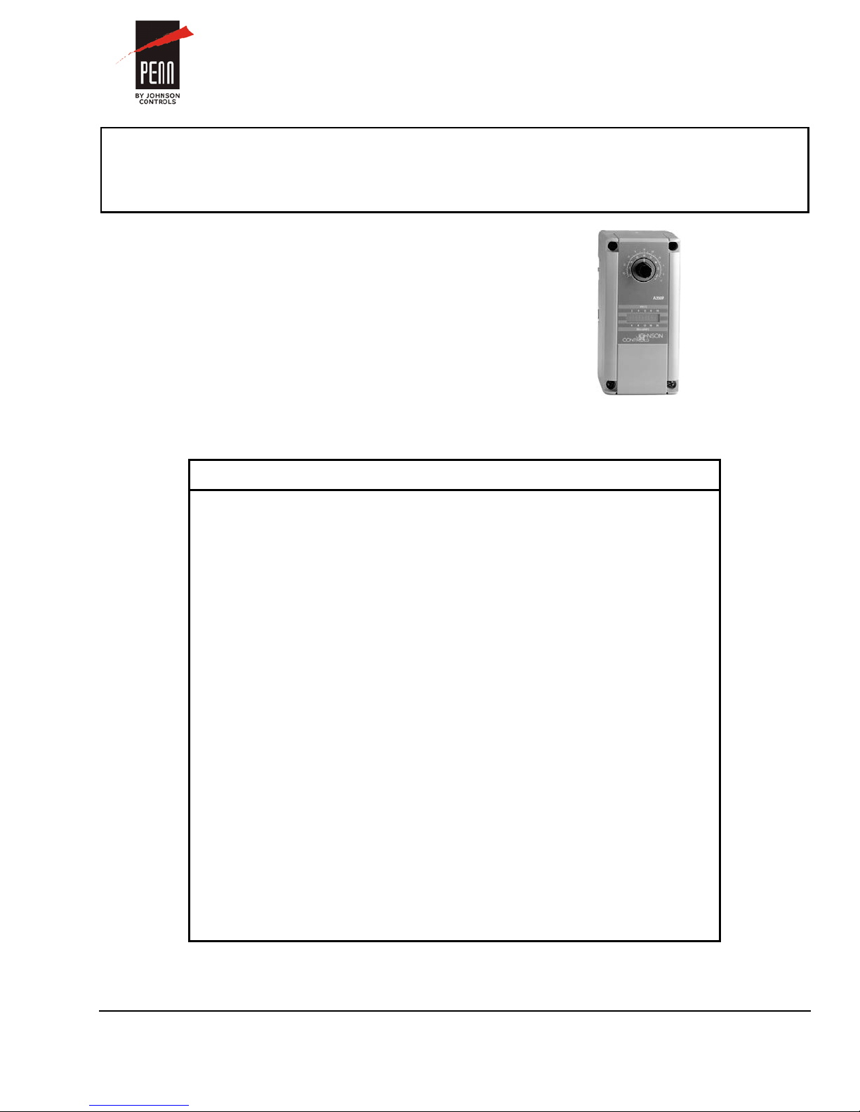
Figure 1: A350P Electronic Proportional Plus
Integral Temperature Control
Two Models Cover a Wide
Setpoint Range of -30 to
250°F (-35 to 121°C)
Minimum Output Adjustable
from 0 to 60%
Adjustable Throttling
Range of 2 to 30F° ( 1 to 17C°)
Field-selectable Rev erse
or Direct Acting Mode
Three User-Selectable
Integration Time Constants
Interchangeable
Temperature Sensors
Reduces inventory by encom passing
temperature ranges requi red to suppo rt the
majority of Heating, Ventilat ion, Air C onditioni ng,
and Refrigeration (HVAC/R) applications
Tailors the output to the req uirements of the
controlled device; can be us ed to set m inimum
valve or damper position
Enables the user to tune the system for optimum
stable performance
Works in heating or cooling applications
Provides selection of the int egration constant fo r
applications requiring propo rtional pl us integral
control
Increase versatility and serviceability
© 2014 Johnson Controls, Inc. 1
Part No. 24-7664-192, Rev. G www.johnsoncontrols.com
Code No. LIT-930020
Page 2
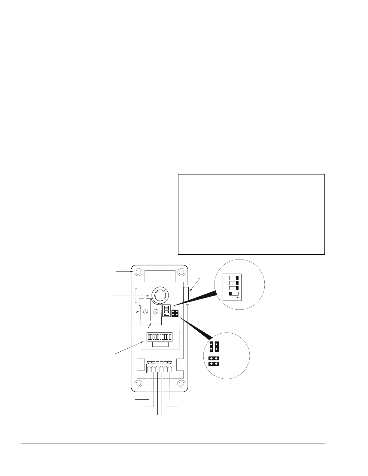
Cover Screw
(One of Four)
Setpoint
Dial
Throttling Range
Potentiometer
Minimum Output
Potentiometer
LED Indicator
(Percent of Output)
V: 0-10 VDC Ou tp ut
I: 0-20 mA Output
SN: Sensor Input
24V: 24 VAC (+)
C: Common (-)
VDC: +5 VDC (not used)
Operation Mode
Jumper Positions
Reverse
Acting (RA)
Direct
Acting (DA)
Module
Connector
Integration DIP switch is
shown in proportional-only position.
THROT
RANGE
MIN
OUTPUT
VIS
NVD
C
C
2
4
V
Fast
Medium
Slow
Off
On
1 2 3 4
Integration
DIP Switch
pplication
A
The A350P Temperature Control can be used as a
standalone device or in conjunction with plug-together
accessory modules. The addition of S350 Stage
Modules allows for the control of multiple stage
HVAC/R applications. Typical application for the
A350P includes:
• proportional heating control with staged direct
expansion cooling
• simple temperature control for air handling units
• modulating damper actuators for mixed air control
• simple proportional mixed air control
A typical System 350 Temperature Control setu p
includes the following:
• A350P Temperature Control
• A99B Series Temperature Sensor
• Y350R Power Module (or 24 VAC Class 2
transformer)
• S350 Stage Modules
• D350 Digital Temperature Display Module
peration
O
The A350P control operates on 24 VAC/VDC and
provides two simultaneous analog outputs:
0 to 10 VDC and 0 to 20 mA. A cover-mounted,
10-segment Light-Emitting Diode (LED) bar graph
indicates percentage of output.
Features include:
• adjustable setpoint
• adjustable minimum output
• adjustable throttling range (proportional b and)
• selectable integration time constant
• selectable Reverse Acting (RA) or Direct Act ing
(DA) mode of operation
IMPORTANT: All System 350 controls are
designed for use only as
operating controls. Where an
operating control failure would
result in personal injury and/or
loss of property, it is the
responsibility of the installer to
add devices (safety, limit controls)
or systems (alarm, supervisory
systems) that protect against, or
warn of, control failure.
Figure 2: Interior View Showing A350P Control’s Featur es
2 System 350 A350P Electronic Proportional Plus Integ ral Temper ature Cont rol Prod uct/Tech nical Bulleti n
Page 3
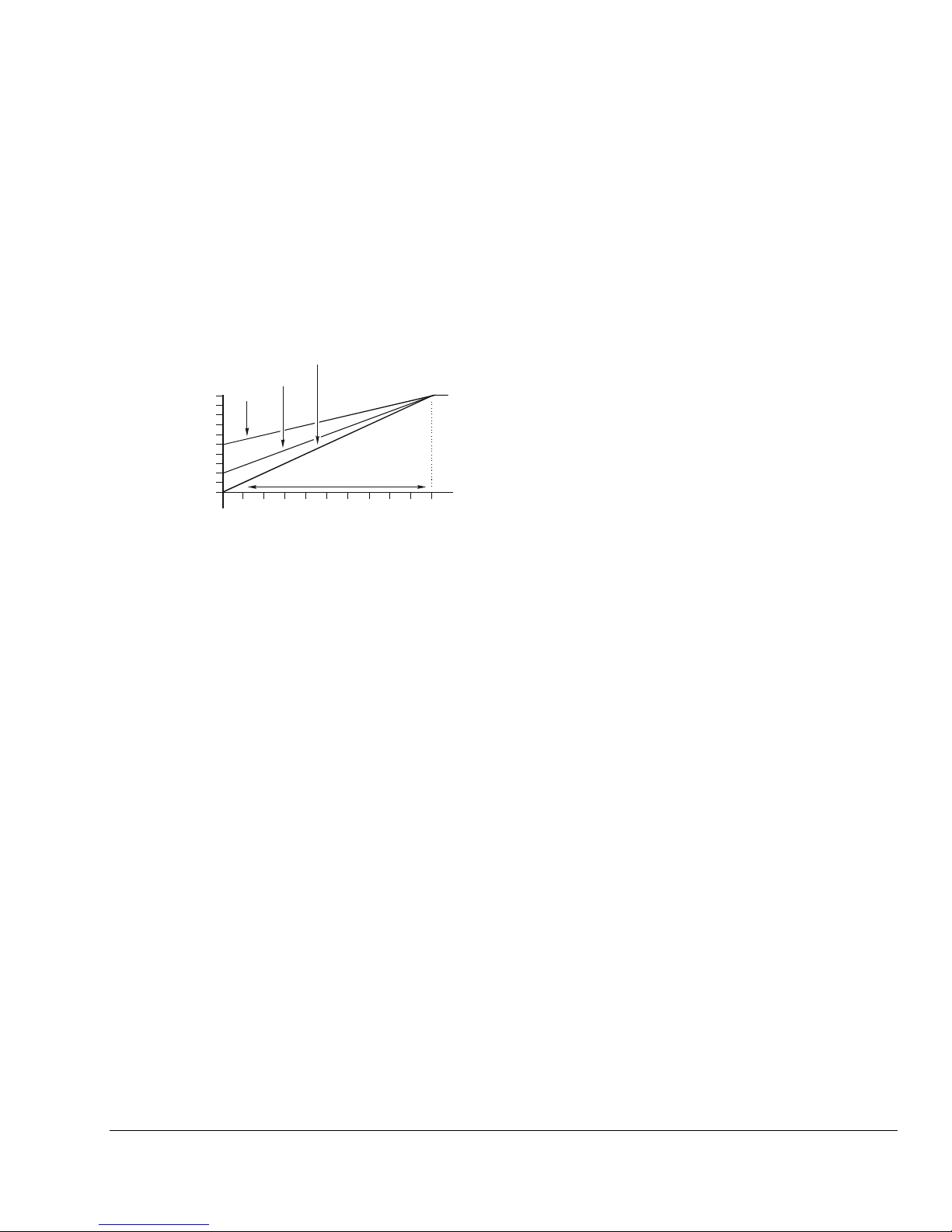
Deviation Above Setpoint (F°)
Output
(mA)
0
2 4 6 8 10 12 14 16 18 20
0
4
10
20
50%
20%
0%
Throttling Range
Minimum Output Adjustment
The minimum output adjustment sets the minimum
voltage or milliampere output provided by t he A 350P
control. It can be adjusted from 0 to 60% (0 t o 6 V DC
or 0 to 12 mA) of the output range.
Example:
A controlled device responding to a 4-20 mA out put
would require the minimum output to be adjusted t o
20% or 4 mA. (See Figure 3.) The minimum output
adjustment may also be used to set valves or dam pers
to minimum positions.
Throttling Range (Proportional Band)
The throttling range is the range over which a control
is active. Throttling range for the A350P control can be
adjusted from 2 to 30F° (1 to 17C°). Make the
adjustment at the throttling range potentiometer
marked THROT RANGE (see Figure 2).
Integration Function
Proportional-only controls cannot hold a process at the
exact setpoint. A proportional offset is alway s present
because the control output is 0% at setpoint. Any load
on the system will cause the control point to be offset
from the setpoint. The greater the load on the system,
the further the control point will be offset from the
setpoint. (This is commonly referred to as proportional
offset, and under maximum load this error will
approach the throttling range.)
Some proportional-only controls are designed with
their setpoint located midway through the proporti onal
band to help compensate for this offset. This results in
a plus/minus error from the setpoint rather t han a
single-ended error. Refer to Figure 4.
Figure 3: Output vs. Deviation from
Setpoint for: Minimum Output = 0, 20, and
50%, Throttling Range = 20°F (DA)
Make the adjustment at the minimum output
potentiometer marked as MIN OUTPUT.
(See Figure 2.) For each 10% increase in output, the
next bar on the LED indicator will light (only one bar is
lit at any time).
Note: Before setting the minimum output
potentiometer, verify that the control reads
zero output (that is, no LEDs are lit).
System 350 A350P Electron ic Proportio nal Plus Int egral Tempe rature Control Prod uct/Tec hnical Bullet in 3
Page 4

Proportional
Offset
Setpoint
Load Change
System Load
Contr ol Point
Follo ws the Load
Temperature
Time
Throttling
Range
Proportional Only Control
Temperature
Proportional
Offset = 0
Setpoint
Load Change
System Load
Integration adjusts the
proportional output to
bring the process to
setpoint regardless of load.
Time
Proportional Plus Integral Control
Figure 4: Comparison Between Proport ional Only and Proportional Plus Integral Control
The A350P control has an integration feature that
forces the control point to match the setpoint . Over
time, the A350P will control the heating/cooling
equipment to balance the system load at t he cont rol
setpoint. (See Figure 4.)
On traditional proportional plus integral controls, the
amount of correction will become too large if the
system load exceeds the capacity of the equipment.
When the actuated device (valve or damper) is ful l y
open or closed and the setpoint still cannot be
reached, the integration error continues to grow. The
result is called integral windup.
The A350P control avoids integral windup with a
patented circuit that puts a dynamic ceiling on the
integrator. This resets the integration error when the
sensor goes just above the setpoint plus the throttling
range (in DA mode) or just below the setpoint minus
the throttling range (in RA mode). This allows the
process to recover from an out-of-range condition
without a large overshoot.
The A350P control has three field-selectable
integration constants and an off position. The
integration DIP switch selects the integration constant.
(See Figure 2 for location.)
The field-selectable integration constant s i nclude:
• OFF: Switch 1 to On position, all others Off
provides proportional-only operation.
Note: In open-loop (without feedback) applications,
select OFF (proportional-only) operation.
Slow (C3): Switch 2 to On position, all others
•
Off is the slowest integration constant (26 minut e),
and is suitable for most proportional plus integral
applications. Slow is the recommended init i al
setting.
Medium (C2): Switch 3 to On position, all
•
others Off selects a 13-minute integration
constant. If the rate of system recovery to set point
is sluggish with the control set to slow, and if the
system has enough capacity to drive the process
to setpoint at a faster rate, the medium sett i ng
may be used.
Fast (C1): Switch 4 in On position, all
•
others Off is the fastest integration constant
(6.5 minutes). Use fast only in instances where the
rate of change at the sensor is extremely rapid
and system capacity can compensate for that
rapid change.
4 System 350 A350P Electronic Proportional Plus Integ ral Temper ature Cont rol Prod uct/Tech nical Bulleti n
Page 5

Note: Dashed areas show throttling range possibilities
from mi nimum to maximum.
VDC
Throttling Range
Setpoint
10
0
RA
20
10
0
mA
Setpoint
Throttling Range
10
0
VDC
DA
20
10
0
mA
5F°
5 10
15 202530F°
+
1015
20
2530
Reverse Acting Direct Acting
Power
Number
Number of
Allowed
Number of
Allowed
Y350R
4 2 0
Transformer
Reverse or Direct Acting Operation
With the operation jumpers in the Reverse Act ing (RA)
position, the analog output increases as t he
temperature drops below setpoint. (See Figure 5.)
With the operation jumpers in the Direct Act ing (DA)
position, the analog output will increase as t he
temperature rises above the setpoint.
Select the RA/DA mode by positioning the operat i on
jumpers vertically or horizontally. (See Figur e 2.)
Position the operation jumpers vertically for RA and
horizontally for DA.
The RA/DA operation jumpers are installed in t he RA
mode at the factory.
S350A On-Off Stage M odules
S350A On-Off stage modules receive power, setpoint,
and sensor input from the A350P control. S350A st age
modules perform switching functions based on the
control’s setpoint and sensor information , as well as
the offset and differential selected at the S 350A st age
module.
For more information on these modules, refer to the
System 350
TM
S350 Temperature, S351 Humidity,
and S352 Pressure On/Off Stage Modules
Product/Technical Bulletin (LIT-930080).
S350C Slave Stage Module
S350C slave stage modules receive power and sensor
input from the A350P control. S350C slave stage
modules perform switching functions based upon the
control’s sensor information, as well as the setpoint
and differential selected at the S350C stage mod ul e.
For more information on these modules, refer to the
System 350
TM
S350C Temperature Slave Stage
Module Product/Technical Bulletin (LIT-930084).
Figure 5: RA and DA Proportional Bands Sho wn in
Proportional-Only Mode
dd-on Modules
A
The maximum number of add-on modules is listed in
Table 1.
Table 1: Maximum Number of S350 Stage
Modules per A350P
Source
External
Class 2
of S350A
or S350C
Stage
Modules
Allowed
9 8 7
S350A or
S350C
Modules
(with
One S350P)
S350A or
S350C
Modules
(with
Two S350Ps)
S350P Proportional Stage Modules
S350P proportional stage modules receiv e power,
setpoint, and sensor input from the A350P control. T he
S350P stage module responds with an analog 0 to
10 VDC and 0 to 20 mA output signal. This is based
upon the control’s setpoint and sensor information, as
well as the offset, throttling range, and minimum output
selected at the S350P stage module.
For more information on these modules, refer to the
System 350
TM
S350P Proportional Plus Integral
Temperature Stage Module Product/Technical Bulletin
(LIT-930086).
System 350 A350P Electron ic Proportio nal Plus Int egral Tempe rature Control Prod uct/Tec hnical Bullet in 5
Page 6

imensions
Mounting Slots
for No. 6 S c rews
DIN
Rail Mount
A350P
Conduit
Hole
3/16 (4)
2 3/8 (61)
1 3/16 (31)
7/8
(22)
7/8 (22)
1 9/16
(40)
7/16 (11)
1
/
4
(
6
)
2 (50)
Sensor
1/2 (13)
2 15/16
(75)
9 3/4 (248)
3 (76)
2 3/8 (61)
4 (102)
5 (127)
!
D
Figure 6: A350P Control and Sensor Dimensi ons, in. (mm)
nstallation and Wiring
I
Celsius Scale Conversion
A Celsius scale throttling range decal is included with
the A350P control. If the Celsius scale is desired:
1. Locate the throttling range and minimum output
potentiometers on the main PC board.
(See Figure 2.) Carefully remove the knobs and
the existing decal.
2. Apply the Celsius scale decal in the same place as
the original decal.
3. Rotate both knob stems completely
counterclockwise (CCW).
4. Reinstall the potentiometer knobs so the arro ws
point to the minimum values.
The A350P Temperature Control is housed in a
compact NEMA 1 plastic enclosure designed for
standard 35 mm DIN rail mounting. Four key-slot
mounting holes on the back of the control case ar e
provided should surface mounting be required. If a
Y350R is used, it should be mounted immediately to
the right of the control. Any S350 modules would
follow on the right, with the D350 being the last module
mounted, also on the right.
Note: When mounting any System 350 module to
rigid conduit, attach the hub to the conduit
before securing the hub to the control
enclosure.
WARNING: Risk of Electrical Shock.
Disconnect the power supply before making
electrical connections. Contact with com ponents
carrying hazardous voltage can cause electric shock
and may result in severe personal injury or death.
AVERTISSEMENT: Risque de décharge
électrique.
Débrancher l'alimentation avant de réaliser tout
branchement électrique. Tout contact avec des
composants conducteurs de tensions dangereuses
risque d'entraîner une décharge électrique et de
provoquer des blessures graves, voire mortelles.
6 System 350 A350P Electronic Proportional Plus Integ ral Temper ature Cont rol Prod uct/Tech nical Bulleti n
Page 7

VISN
VDC
Terminal
Description
I
VDC
C
Wire
Shielded Cable Length
Gauge
16 AWG
22 AWG
(-40 to 100°C)
A350PS-2C
(-40 to 120°C)
A350PT-1C
A350BA-2C
Wiring Terminals
Install all wiring to conform to the National Electrical
Code and local regulations. For maximum el ect rical
rating of control, refer to the label inside the control
cover. Terminals will accept 12 to 26 AWG wire. Us e
only copper conductors.
1. Use a 1/8 in. (3 mm) flat-blade screwdriver to push
the clamp arm down.
2. Insert the appropriate wire into the opening.
Refer to Table 2 for terminal designations.
3. Release the clamp arm to secure the wire.
See Figure 7.
Sensor Connection
Shielded cable is not generally required for sensor
wiring on runs of less than 50 feet. When using
shielded cable, isolate and tape the shield at the
sensor. Connect the shield to Terminal C on the
A350P control.
Refer to Table 3 for the maximum recommended cable
lengths for particular sizes of wire.
Table 3: Maximum Recommended
Sensor Cable Lengths
Feet Meters
14 AWG
18 AWG
20 AWG
• Various A99B Series Temperature Sensors and
mounting hardware are available for use with
A350P Series controls.
800 244
500 152
310 94
200 61
124 38
Figure 7: Cage Clamp Terminal Block
Table 2: Terminal Designations
V
SN
24V
Note: Output signals from the A350P control vary
from 0 to 10 VDC and 0 to 20 mA. (Both
outputs can be used simultaneously.)
Connections can be made to both the V and
I terminals, allowing the control to drive
two outputs from the same RA or DA ramp
simultaneously. This feature can be used to
drive motor actuators of different types i n a
single application.
0 to 10 VDC output
0 to 20 mA output
Temperature sensor input
5 VDC power supply (not used)
Common for power supply,
temperature sensor, and outputs
24 Volts AC
The sensor must be connected to Terminals SN
and C. (See Figure 2.) The sensors are not
polarity sensitive.
• The sensor must be mounted so that it can
accurately sense the temperature of the controlled
medium.
Table 4: A350P Controls And Sensors
Control Sensor Included
Sensor Lead Length is 9-3/4 in.
(0.25 m)
A350PS-1C
A350PS-1CM
A99BB-25C; Range: -40 to 212°F
A99BB-25C; Range: -40 to 212°F
(-40 to 100°C)
A99BC-25; Range: -40 to 248°F
(-40 to 120°C)
A350PS-2CM
A99BC-25; Range: -40 to 248°F
No Sensor Included
A99BC-25; Range: -40 to 248°F
(-40 to 120°C)
• For more information regarding sensor options
and installation, refer to the A99B Series
Temperature Sensors Product/Technical Bulletin
(LIT-125186).
System 350 A350P Electron ic Proportio nal Plus Int egral Tempe rature Control Prod uct/Tec hnical Bullet in 7
Page 8

djustments
A
Follow this procedure to set up the A350P control f or
the types of operation desired.
1. Remove its cover by loosening the four captive
cover screws. (See Figure 2.)
2. Set the RA/DA operation jumpers to the desired
mode of operation. Position the operation j um pers
vertically for RA (Reverse Acting) or hor i zont all y
for DA (Direct Acting). (See Figure 2.)
3. Adjust the throttling range potentiometer to desired
setting. Rotate Clockwise (CW) to increase t he
throttling range.
Notes: Included with the control is a Celsius scale
throttling range decal. If the Celsius scale i s
desired, refer to the Celsius Scale Conv ersion
section for decal installation instructions .
If the A350P is to be used in proportional plus
integral control, the initial throttling range
adjustment is seldom set below 6F° (3C°).
A narrow proportional band used in
conjunction with the integration may result i n
unstable control.
4. If minimum output is required, set the minimum
output potentiometer (see Figure 2) to the desired
position. The 10-segment front LED panel or a
voltmeter can be used to read the minimum
output. (The minimum setting for the control is
designated by the 0 on the decal.)
Notes: Before adjusting the minimum output
potentiometer, verify that the control reads
zero output (that is, no LEDs are lit).
For each 10% increase in output, the next
bar will light on the LED bar graph (only
one bar is lit at anytime). In a milliampere
application, each bar equals 2 mA. In a
voltage application, each bar equals 1 VDC.
(Refer to Figure 3.)
Example:
To set the control for a minimum output of
4 mA, turn the minimum output potentiometer
clockwise until the second LED segment just
lights.
If the control system does not function properl y, verify
that the proper operation mode is selected on ea ch
module (DA or RA), and perform the following
procedures to determine the cause of the problem:
1. Check for proper voltages on the A350P control.
5. Make sure the system is stable in the proportional
mode before selecting integration. Refer t o the
Checkout Procedure section.
6. Reinstall the cover and secure in pl ace with the
four captive cover screws.
7. Adjust the setpoint dial to the desired setpoint.
If using the D350 Display Module, press and hol d
the setpoint button on the D350 while rotating t he
setpoint dial.
Note: The control’s setpoint is factory calibrated at
midscale to a tolerance of ±1F° (0.6C°). The
setpoint tolerance at the extreme ends of the
setpoint scale may be ± 4F° (2.2C°). The
D350 Display Module is unaffected by this
tolerance shift. Use the D350 for the most
accurate setpoint selection.
heckout Procedure
C
Follow this procedure to verify the A350P control is
connected and functioning properly.
1. Before applying power, make sure that the
installation and wiring connections are acc ording
to job specifications.
2. Set up the system for proportional mode
(Integration = OFF), and make any necessary
adjustments to the setpoint, throttling range, and
minimum output. Then select Reverse or Direct
Acting mode.
3. After making adjustments and electrical
connections, apply power to the system, and
observe it for stable operation.
4. If integration is required, select the fast (C1),
medium (C2), or slow (C3) integration constant.
Slow is the recommended initial setting. (Ref er to
the Integration Function section.)
5. Put the system back into operation. If instability
occurs, consider increasing the throttling range.
roubleshooting
T
a. Connect a digital voltmeter (DVM) between
Terminals 24V (+) and C (-) located on the
A350P’s terminal block. (See Figure 2.)
If an external transformer is used, select AC
volts on the DVM. Verify that the voltage is
between 20 and 30 VAC.
8 System 350 A350P Electronic Proportional Plus Integ ral Temper ature Cont rol Prod uct/Tech nical Bulleti n
Page 9

°F
Temperature
260
240
220
200
180
160
140
120
100
80
60
40
20
0
-20
-40
500
700 900
1100
Resistance (Ohms)
1300 1500
1700 1900
2100
°C
120
100
80
60
40
20
0
-20
-40
If a Y350R Power Module is used, select DC
volts on the DVM. Verify that the voltage is
between 16 and 38 VDC.
If an external DC power supply is used, select
DC volts on the DVM. Verify that the voltage is
between 22 and 29 VDC.
b. If the DVM reading is within the indicated
voltage range, select DC volts on the DVM
(DVM must be accurate to +/-0.01 VDC), and
connect the (+) lead to Terminal VDC and the
(-) lead to Terminal C.
If the DVM voltage is between 4.9 and
5.1 VDC, proceed to Step 2.
If the DVM voltage is above 5.1 VDC, replace
the A350P.
c. If the DVM voltage is below 4.9 VDC, check
the control using the following procedure.
Disconnect all loads from the A350P control.
(If in Direct Acting mode with power on, the
system will go to full output when the sensor is
disconnected. Thus, ensure that any loads are
disconnected before disconnecting the
temperature sensor.)
Disconnect the temperature sensor
completely, and recheck the DVM voltage.
2. Check sensor for proper resistance at a given
temperature. (The resistance across the sensor
changes with the temperature of the sensor. )
a. Disconnect power from the A350P control.
b. Disconnect the sensor from the control and
measure the resistance across sensor leads.
c. When measuring the sensor’s resistance, use
an accurate thermometer to measure the
temperature at the sensor.
d. Refer to Figure 8 to determine the optimal
resistance for the measured temperature.
e. If the measured resistance varies substantially
from the optimal resistance for that
temperature, the sensor or wiring must be
replaced.
f. If the sensor’s resistance conforms to the
chart in Figure 8, reconnect the sensor to the
control.
g. Reconnect power to the control.
Note: The sensor reading indicated by the D350
may differ somewhat from thermometer
readings due to sensor tolerances, time
constants, thermometer accuracy, and ot her
factors.
If the DVM voltage rises to a value between
4.9 and 5.1 VDC, replace the sensor.
If the DVM voltage is still below 4.9 VDC,
replace the A350P control.
System 350 A350P Electron ic Proportio nal Plus Int egral Tempe rature Control Prod uct/Tec hnical Bullet in 9
Figure 8: Temperature vs. Resistance Chart for the
A99B Series Sensor
Page 10

3. Check the A350P control for proper operation.
Note: Perform Steps 1 and 2 first.
a. Reconnect the sensor to the control and
re-apply power.
b. Turn the throttling range and the minimum
output to minimum by turning both
potentiometers counterclockwise.
c. Switch off the integration.
d. Select the RA mode.
e. Connect the DVM (+) lead to the A350P
control’s Terminal SN and the (-) lead to
Terminal C.
If the sensor voltage is less than 1.8 VDC on
model A350PS-1C or less than 2.3 VDC on
model A350PS-2C, go to Step 3g.
f. If the voltage is greater than 1.8 VDC on
model A350PS 1C or greater than 2.3 VDC on
model A350PS-2C, adjust the setpoint to
120°F (49°C) on model A350PS-1C or 240°F
(116°C) on model A350PS-2C.
The output Terminal V should be less than
0.1 VDC, and all LEDs in the bar graph display
should be off. If not, replace the A350P.
g. If the sensor voltage is above 1.1 VDC
on A350PS-1C or above 1.6 VDC on
A350PS-2C, adjust the setpoint to match t he
actual temperature (Ts). The output Terminal
V should be less than 0.1 VDC, and all LEDs
in the bar graph should be off.
Note: Some tolerance error is present betwee n the
setpoint scale and the setpoint knob pointer.
Refer to the Adjustments section.
1. Make sure the A350P control is in RA
mode.
2. Increase the setpoint in increments of 2F°
(1C°).
3. As the setpoint is increased, the control’s
Terminal V output voltage should go from
0 to 10 VDC, the Terminal I output current
should go from 0 to 20 mA, and the LEDs
should turn on, one at a time from left to
right.
4. If the LEDs do not turn on and if the
outputs of terminals V and I do not change
as described above, replace the control.
h. Readjust the A350P control to the desired
control settings.
1. Adjust the minimum output to the
maximum by turning the potentiometer
CW. As the potentiometer is turned CW,
the LEDs in the bar graph should turn on
from left to right until the fifth or sixth bar is
on. If not, replace the A350P control.
2. Adjust the minimum output to zero again,
and select the DA mode.
3. If the right most LED in the bar graph is on
(Terminal V = 10 VDC, Terminal I = 20 mA),
go to Step 3h. If the LED is not on, replace
the A350P.
epairs and Replacement
R
Do not make field repairs or perform calibrati on.
A99B Temperature Sensors and replacement controls
are available through the nearest Johnson Controls
representative. (See Tables 5 and 6 for orderin g
information.)
10 System 350 A350P Electroni c Proport ional Plus I ntegral Te mperat ure Control P roduct/T echnical Bulletin
Page 11

rdering Information
Item
Product Code Number
Description
(Sensor not included)
Display Modules
D350BA-1C
Digital Temperature Display Module (Celsius Scale)
On/Off Stage Modules
S350AB-1C
Celsius Scale
Slave Stage Module
Proportional Stage Modu le
24 VAC Output
Item
Product Code Number
Description
Wall Mount Plate
Duct Mounting
Conduit Adaptor
Immersion Well
WEL11A-601R
For liquid sensing applications
DIN Rail Sections
DIN Rail End Clamp
PLT344-1R
Consists of two end clamps
O
Table 5: System 350 Products
A350P Proportional Plus Inte gral
Temperature Controls
Power Module
A350PS-1C
A350PS-2C
A350PT-1C
D350AA-1C
S350AA-1C
S350CC-1C Dual Scale (°F and °C)
S350PQ-1C Dual Scale (°F and °C)
Y350R-1C 120 or 240 VAC, 50/60 Hz Input, Rectified Class 2,
Table 6: System 350 Accessories
Range: -30 to 130°F (-35 to 55°C)
Throttling Range: 2 to 30 F° (1 to 17C°)
(Includes the A99BC-25C Temperature Sensor)
Range: 90 to 250°F (30 to 120°C)
Throttling Range: 2 to 30 F° (1 to 17C°)
(Includes the A99BC-25C Temperature Sensor)
Range: -30 to 130°F (-35 to 55°C)
Throttling Range: 2 to 30F° (1 to 17C°)
Digital Temperature Display Module (Fahrenheit Scale)
Fahrenheit Scale
TE-6001-4 Includes sensor mounting clip
Cover
Mounting Clip
Duct Mounting
Sun Shield
Cables for Remote Mounting of
D350 Display Module
T-4000-2644 For wall mount plate
A99-CLP-1 Surface mounting clip for the A99B Temperature Sensor
TE-6001-1 Duct-mounting hardware with handy box
TE-6001-11 Duct-mounting hardware without handy box
ADP11A-600R 1/2 in. snap-fit EMT conduit adaptor (box of 10)
SHL10A-603R For use with outside sensors in sunny locations
BKT287-1R
BKT287-2R
WHA29A-600R*
WHA29A-603R
WHA29A-604R
12 in. (0.3 m) long
39-1/3 in. (1.0 m) long
3 ft (0.9 m)
25 ft (7.6 m)
50 ft (15.2 m)
*WHA29A-600R may be used to daisy chain S350 modules together.
System 350 A350P Electron ic Proportio nal Plus Int egral Tempe rature Control Prod uct/Tec hnical Bullet in 11
Page 12

Product
A350P Proportional Plus Time Integral Temperature Control
Note: Only one supply voltage source may be used.
Power Consumption
3.2 VA maximum
Shipping: -40 to 185°F (-40 to 85°C)
Humidity (all modules)
0 to 95% RH non-condensing; maximum dew point 85°F (29°C)
A350PT-1C: -30 to 130°F (-35 to 55°C)
Range
Analog Outputs
0 to 10 VDC (550 ohm load minimum) and 0 to 20 mA (600 ohm load maximum)
Minimum Output
Adjustable from 0 to 60% of the output
Output Indication
A ten segment LED bar graph indicates percentage of output.
Control Action
Direct or reverse action is jumper selectable.
Integration Constant
Four selectable rates: fast, medium, slow, and off
Reference resistance 1035 ohms at 77°F (25°C)
Material
Case and cover: NEMA 1 high-impact thermoplastic
UL Listed for Canada, CCN XAPX7, File E27734
Building Efficiency
pecifications
S
Supply Voltage Y350R Power Module: Input: 120/240 VAC 50/60 Hz
Output: 24 VDC, unfiltered, 10 VA
External Source: 24 VAC, 50/60 Hz, Class 2 (20-30 VAC)
Ambient Temperature Operating: -30 to 150°F (-34 to 66°C)
Setpoint Adjustment Ra nge A350PS-1C: -30 to 130°F (-35 to 55°C)
A350PS-2C: 90 to 250°F (30 to 120°C)
Throttling Adjustm ent
Sensor Replaceable positive temperature coefficient sensor
Agency Listing UL Listed, CCN XAPX, File E27734
The performance specifications are nominal and conform to acceptable industry standards. For application at conditions beyond these specifications,
consult Johnson Controls Application Engineering at (414) 274-5535. Johnson Controls, Inc. shall not be liable for damages resulting from misapplication
or misuse of its products.
2 to 30F° (1 to 17C°)
® Johnson Controls and PENN are regi s tered trademarks of Johnson Controls, Inc. in the
United States of America and/or ot her countries. All other trademarks used herein are the property
of their respective owners. © Copyright 2014 by Johnson Controls, Inc. All rights res er ved.
12 System 350 A350P Electroni c Proport ional Plus I ntegral Te mperat ure Control P roduct/T echnical Bulletin
507 E. Michigan Street, Milwaukee, WI 53202
 Loading...