

Johnson Controls System 350 P352AB Series, System 350 P352AB-2, System 350 P352AB-3, System 350 P352AB-4 Product Manual
Page 1
System 350 Product Guide 930
Basic Controls Section
Product/Technical Bulletin P352AB
Issue Date 0200
System 350
P352AB Electronic Pressure Control Series
The P352AB controls are On/Off electronic pressure
controls with Single-Pole, Double-Throw (SPDT) relay
output and Light-Emitting Diode (LED) indication. The
P352AB controls are designed with Reverse or Direct
Acting mode of operation, adjustable differential, and
an interchangeable pressure transducer. The P352AB
control will accept S352A Stage Modules to control
stages of Heating, Ventilating, and Air Conditioning
(HVAC) and/or refrigeration equipment.
Three models cover the ranges of 0-100 psi,
90-250 psi, and 240-600 psi, covering most common
refrigeration and air conditioning applications.
As are all System 350™ products, the P352AB control
is housed in a NEMA 1 high-impact thermoplastic
enclosure. The modular design provides easy,
snap-together connections for quick installation and
future expandability.
Figure 1: P352AB Electronic Pressure Control
Modular Design
❑
Plug-together Connectors
❑
and 35 mm DIN Rail
Mounting
Three Models Available
❑
with Adjustable Setpoint
Ranges of 0-100 psi,
90-250 psi, and 240-600 psi
Models Available with
❑
Adjustable Differential from
2-50 psi and 10-100 psi
Field-selectable Direct or
❑
Reverse Acting Mode
Interchangeable Pressure
❑
Transducer
Features and Benefits
Provides the flexibility to add S352A Stage
Modules, D352 Display Module, and Y350R
Power Module
Eliminates wiring between modules and
reduces installation costs
Handles pressures required for most fan
cycling and compressor unloading
applications
Enables user to match the equipment cycle
rate and/or sequencing for a given application
Energizes relay output on either an increase
or a decrease in pressure
Increases versatility and serviceability
© 2000 Johnson Controls, Inc.
Part No. 24-7664-1903, Rev. — www.johnsoncontrols.com
Code No. LIT-930038
1
Page 2
pplication
A
The P352AB Electronic Pressure Control can be used
as a standalone device or in conjunction with
System 350 plug-together accessory modules for
single or multiple stage refrigeration and HVAC
pressure control applications. Typical applications
include:
●
condenser fan cycling
●
compressor cycling and unloading
IMPORTANT: The System 350 controls are
intended to control equipment under
normal operating conditions. Where
failure or malfunction of the
System 350 controls could lead to an
abnormal operating condition that
could cause personal injury or
damage to the equipment or other
property, other devices (limit or
safety controls) or systems (alarm or
supervisory systems) intended to
warn of, or protect against, failure or
malfunction of the System 350
controls must be incorporated into
and maintained as part of the control
system.
A typical System 350 pressure control setup includes
the following:
●
P352AB Electronic Pressure Control
●
S352A Stage Modules
●
D352 Digital Display Module
●
Y350R Power Module (or 24 VAC transformer)
●
P399 Electronic Pressure Transducer
IMPORTANT: The P352AB controls use an input
signal from the P399 Electronic
Pressure Transducer to determine
pressure in psi (pounds per square
inch). The P399 transducer uses a
sealed-reference of one atmosphere
to determine 0 psi. For more
information on interpreting control
pressure readings, refer to the
P399 Electronic Pressure Transducer
Product/Technical Bulletin,
LIT-125515
.
Setpoint
Setpoint is defined as the pressure at which the relay
de-energizes. The setpoint is adjustable between
0 to 100, 90 to 250, and 240 to 600 psi, depending on
the model ordered. (See Table 1.)
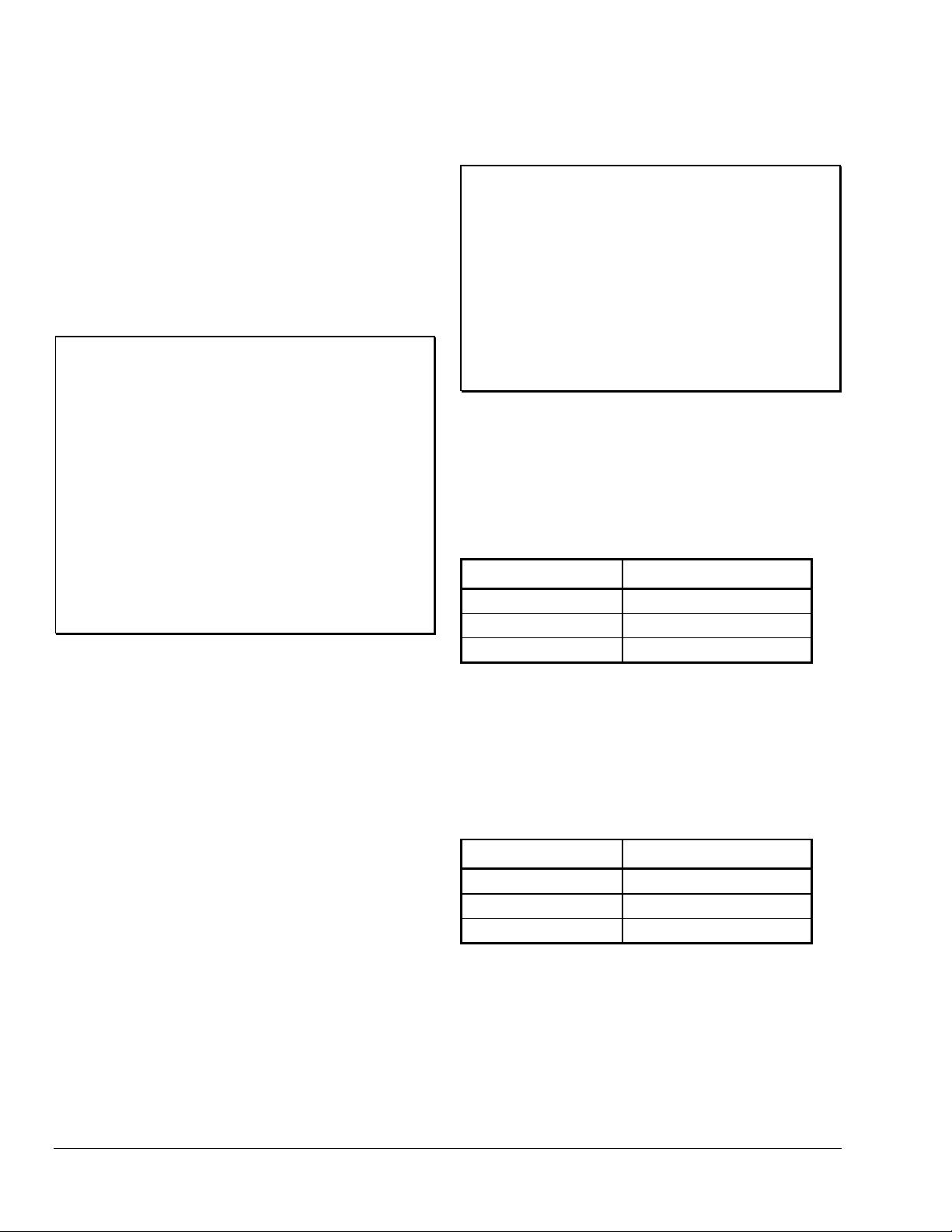
Table 1: Setpoint Adjustment Range
P352AB Model No. Setpoint Range
P352AB-2
P352AB-3
P352AB-4
0 to 100 psi
90 to 250 psi
240 to 600 psi
Differential
Differential is defined as the difference in pressure
between energization and de-energization of the
output relay. The differential is adjustable between
2 to 50 and 10 to 100 psi, depending on the control
model. (See Table 2.)
Table 2: Differential Adjustment Range
peration
O
The P352AB Electronic Pressure Control operates on
24 VAC and has an SPDT relay output. A front panel
LED lights to indicate when the relay is energized.
P352AB Model No. Differential Range
P352AB-2
P352AB-3
P352AB-4
2 to 50 psi
10 to 100 psi
10 to 100 psi
The P352AB controls are used with the P399
Electronic Pressure Transducers, which are available
in several pressure ranges, and provide a ratiometric
analog signal (0.5 to 4.5 VDC), based on the sensed
pressure.
2
Basic Controls—System 350 P352AB Electronic Pressure Control Series Product/Technical Bulletin
Page 3
Direct/Reverse Acting Mode
The P352AB controls utilize jumpers (at Jumper
Terminal J1) to select the operation mode. (See
Adjustments (P352AB Control)
When in
Direct Acting (DA) mode
section and Figure 3.)
, the relay
de-energizes when the pressure drops below the
setpoint. When the pressure rises above the setpoint
plus
the differential, the relay energizes and the “ON”
LED illuminates.
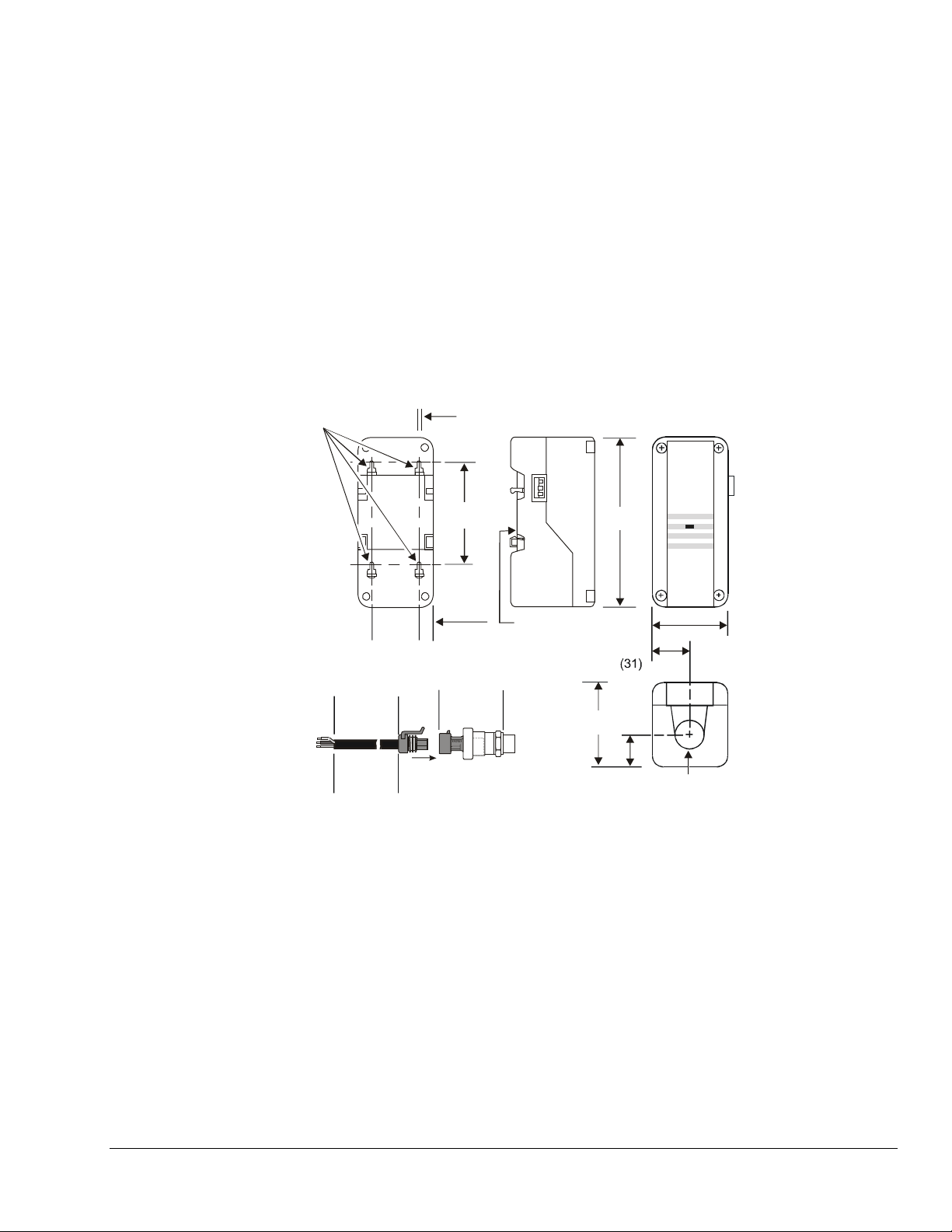
imensions
D
Mounting Slots
For No. 6 Screws
1/8 (4)
2-15/16 (75)
When in
Reverse Acting (RA) mode
, the relay
de-energizes when the sensed pressure rises above
the setpoint. When the pressure drops below the
setpoint
minus
the differential, the relay energizes and
the “ON” LED illuminates.
Note: The P352AB controls are configured for DA
mode at the factory.
Refer to Figure 5 for an example of a typical Direct
Acting/Reverse Acting application.
5 (127)
ON
JOHNSON
CONTROLS
CONTROLS
P352
O
O
1-1/2
(40)
Wiring Harness
6-1/2 ft
(2.0 m)
or
13 ft
(4.0 m)
7/16
(11)
2-1/4 (57)
P399 Transducer
Figure 2: P352AB Control Dimensions, in. (mm)
ounting
M
The P352AB Electronic Pressure Control is housed in
a compact NEMA 1 plastic enclosure designed for
standard 35 mm DIN-rail mounting. Four key-slot
mounting holes on the back of the control case are
provided for surface mounting. (See Figure 2.)
DIN Rail
Mount
1-3/16
2-3/8 (61)
7/8 (22)
2-3/8
(61)
Conduit
Hole
7/8 (22)
Note: When mounting the P352AB control (or any
System 350 Module) to rigid conduit, attach
the hub to the conduit before securing the hub
to the control enclosure.
Basic Controls—System 350 P352AB Electronic Pressure Control Series Product/Technical Bulletin
3
Page 4
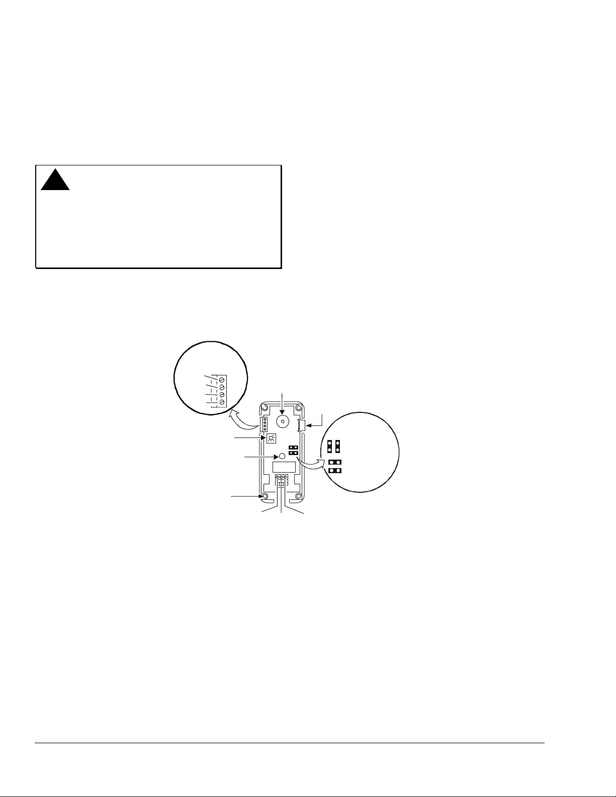
djustments (P352AB Control)
A
Perform the following steps to adjust the P352AB
control settings. (See Figure 3.) Refer to Figure 5 for
an example of the P352AB control in a typical Direct
Acting/Reverse Acting application.
!
WARNING:
Risk of Electrical Shock.
Disconnect power supply to
avoid possible electrical shock or
equipment damage. More than
one disconnect may be required
to completely de-energize
equipment.
1. Ensure all power to system is off.
Set the mode of operation
3.
by positioning the
jumpers (at Jumper Terminal J1) horizontally for
Direct Acting or vertically for Reverse Acting.
Note: The P352AB controls are configured in the
DA mode at the factory.
Adjust the differential
4.
using the potentiometer
marked DIFF ADJUST to the desired setting.
Clockwise rotation increases the differential.
Adjust the setpoint
5.
using the setpoint adjustment
dial to the desired setting.
After power is applied to the control, a more
accurate setting of the setpoint can be made by
utilizing the D352A Pressure Display Module.
2. Remove the P352AB control cover by loosening
the four captive cover screws.
Wire
Ter min al
Block
24V
COM
VDC
SEN
Differential
Potentiometer
Relay Energized
LED Indicator
Cover Screw
(One of Four)
Concealed Setpoint
Adjustment Dial
N.C.
Relay
Figure 3: Interior View and Typical Wiring of the P352AB Control
dd-On Modules
A
6. Replace the cover on the control and fasten in
place with screws.
7. Restore power to system.
Module
Connector
Jumper
Position at J1
Reverse Acting
Relay
COM
Output
N.O.
Terminals
Direct Acting
The Y350R Power Module, D352 Digital Pressure
Display, and S352A Stage Modules snap together and
plug into the P352AB Electronic Pressure Control via
connectors on both sides of each add-on module.
Y350R Power Module
The Y350R Power Module provides a convenient
The Y350R Power Module can be plugged into the
right side of the P352AB controls or any of the add-on
modules. The Y350R Power Module is capable of
providing power to a P352AB control, a D352 Display
Module, and up to five S352A Stage Modules. (Refer
System 350
to the
TM
Y350R Power Module
Product/Technical Bulletin, LIT-930090
information.)
method of powering System 350 modules from a
120 or 240 VAC power source.
4
Basic Controls—System 350 P352AB Electronic Pressure Control Series Product/Technical Bulletin
, for more
Page 5

D352 Digital Pressure Display Module
The D352 Display Module receives power, sensor, and
setpoint information from the P352AB control. A
three digit Liquid Crystal Display (LCD) gives a
continuous readout of the sensed pressure. Pushing
the PRESS FOR SETPOINT button displays the
setpoint of the adjoining P352AB control. The button
must be pressed for approximately three seconds.
(Refer to the
System 350
Product/Technical Bulletin, LIT-930070,
information.)
TM
Display Modules
for more
!
WARNING:
Risk of Electrical Shock.
Disconnect power supply to
avoid possible electrical shock or
equipment damage. More than
one disconnect may be required
to completely de-energize
equipment.
1. Ensure all power to system is off.
S352A Pressure Stage Modules
The S352A Stage Modules receive power, setpoint,
and sensor input from the P352AB controls. As many
as five S352A Stage Modules can plug into the
P352AB controls when powered by the Y350R Power
Module. When powered by an external transformer,
the P352AB controls can use up to nine S352A Stage
Modules. (Refer to the
System 350
Temperature, S351A Humidity, and S352A Pressure
Stage Modules Product/Technical Bulletin,
LIT-930080,
for more information.)
Note: When using an external transformer, the
Y65 Series or other 40 VA Class 2
transformers are recommended.
!
CAUTION: Verify that the jumpers are in the
proper position before powering
System 350 components. If the
jumpers on the P352AB control
or the S352A Stage Module are
in the wrong position, the device
will activate the relay in response
to the opposite signal. The
DA/RA relay will remain
energized until the error is
corrected.
TM
S350A
Each stage module may be receiving separate
power sources. Make sure all power sources to
each stage module are off.
2. Remove the stage module cover by loosening the
four captive cover screws.
Set the mode of operation
3.
by positioning the
jumpers (at Jumper Terminal J2) horizontally for
Direct Acting or vertically for Reverse Acting.
Adjust the differential
4.
using the potentiometer
marked DIFF to the desired setting.
Adjust the offset
5.
using the potentiometer marked
OFFSET to the desired pressure from the P352AB
control setpoint at which the stage relay will
de-energize (above setpoint with Direct Acting
mode selected or below setpoint with Reverse
Acting mode selected).
6. Replace the S352A stage module cover and
tighten the captive cover screws.
7. Restore power to system.
Offset
Potentiometer
Module
Connector
Differential
Potentiometer
Module
Connector
Jumper
Position at J2
djustments (S352A Stage Module)
A
Perform the following steps to adjust the S352A stage
module settings. (See Figure 4.) Refer to Figure 5 for
an illustration of the S352A Stage Modules in a typical
Direct Acting/Reverse Acting application.
Basic Controls—System 350 P352AB Electronic Pressure Control Series Product/Technical Bulletin
Relay Energized
LED Indicator
Cover Screw
(One of Four)
N.C.
Relay
Relay
COM
Output
N.O.
Terminals
Reverse Acting
Direct Acting
Figure 4: Interior View and Typical Wiring
of the S352A Stage Module
5
Page 6

Higher
Pressure
Setpoi nt
Pressure
Lower
Pressure
ON
Differential
OFF
ON = Energized
OFF = De-energized
P352AB
Stage
1
S352A
Stage
OFF
OFFSET
2
ON
Differential
OFFSET
OFF
Differential
ON
3
OFFSET
OFF
Differential
ON
S352A
Stage
4
Direct
Figure 5: Typical Direct Acting/Reverse Acting Application
Using One P352AB Control and Three S352A Stage Modules
iring
W
Refer to the following guidelines and wiring diagrams
for proper wiring and terminal designations.
(See Table 3 and Figures 6 and 7.)
!
WARNING:
Risk of Electrical Shock.
Disconnect power supply before
making electrical connections to
avoid possible electrical shock or
equipment damage. More than
one disconnect may be required
to completely de-energize
equipment.
IMPORTANT: Make all wiring connections in
accordance with the National
Electrical Code and all local
regulations. Use copper
conductors only. Do not exceed
the control’s electrical ratings.
Reverse
Transducer Wiring
The P352AB control supplies 5 VDC power to the
P399 Electronic Pressure Transducer. The transducer
is wired to three of the four connectors at the terminal
block, located at the upper left of the circuit board.
(See Figures 6 and 7.)
The transducer wiring harness has a shielded cable.
Any additional length of cable should also be shielded
cable. Connect the cable shield to the COM terminal
on the P352AB control. Do not connect the other end
of the cable shield.
Table 3: Connecting the Transducer
to the P352AB Control
P352AB Control
Terminal
Designations
COM
SEN
VDC
P399 Electronic
Pressure Transducer
Wire Colors
Black (Common and Shield)
White (Output Signal)
Red (5 VDC Supply)
6
Basic Controls—System 350 P352AB Electronic Pressure Control Series Product/Technical Bulletin
Page 7

N.C.
Relay
120 VAC
24
VAC
Wire
Ter min al
Block
24V
COM
VDC
SEN
COM
Output
N.O.
Terminals
White-SEN
Red-VDC
Black-COM
Shield (Connect
only to COM on P352AB)
P352AB D352AS352A
Wiring Harness
Isolat e and tape. Do not ground
this end of cable shield.
LoadLoad
P399 Transducer
Figure 6: System 350 Powered by an External Transformer Using 120 VAC Power Supply
Wiring Harness
Isolat e and tape. Do not ground
this end of cable shield.
S352A
S352A
N.C.
Relay
Wire
Ter min al
Block
24V
COM
VDC
SEN
COM
Output
Terminals
120 VAC
White-SEN
Shield (Connect
only to COM on P352AB)
P352AB
N.O.
Red-VDC
Black-COM
Y350R S352A
P399 Transducer
D352A
Load Load Load Load
Figure 7: System 350 Powered by a Y350R Power Module Using 120 VAC Power Supply
Basic Controls—System 350 P352AB Electronic Pressure Control Series Product/Technical Bulletin
7
Page 8

heckout Procedure
C
Before applying power, make sure installation and
wiring connections are according to job specifications.
After necessary adjustments and electrical
connections have been made, put the system in
operation and observe at least three complete
operating cycles before leaving the installation.
roubleshooting
T
If the System 350 control modules do not appear to
function properly, verify that the proper mode (DA or
RA) has been selected on each control module. Then
perform the following procedures to determine the
problem.
IMPORTANT: The control and the controlled
equipment must be powered and
operating at a stable pressure to
perform many of the following
procedures.
Equipment Needed:
A reliable pressure gauge connected near the
•
transducer.
A reliable and accurate Digital Voltmeter (DVM)
•
capable of measuring AC voltage and DC voltages
down to ± 0.1 VDC in the 0 to 10 VDC range.
!
WARNING:
1. Check for proper supply voltage to the Control.
Risk of Electrical Shock.
To perform the following
procedures it is necessary to
power the control and the
controlled equipment while the
control cover is removed. Do not
touch any exposed metal
components with anything other
than properly insulated tools or
insulated probes of the digital
voltage meter. Failure to use
properly insulated tools and
probes can result in severe
electrical shock if live line voltage
parts are contacted.
c. With the DVM, check the voltage between the
24V and the COM terminals on the terminal
block on the upper left side of the control.
If an external 24 VAC transformer powers
the control
voltage must be between 20 and 30 VAC.
If a Y350R Power Module powers the
control
voltage must be between 16 and 38 VDC.
d. If the DVM reading is within the indicated
voltage range, proceed to Step 2.
e. If the DVM reading is
voltage ranges, replace the external
transformer or the Y350R Power Module, and
recheck for proper supply voltage.
2. Check for proper supply voltage to the
pressure transducer.
a. Select DC volts on the DVM and measure the
voltage (
terminals on the terminal block on the upper
left side of the control.
The voltage must be 5.0 VDC (± 0.1 VDC).
If the voltage is in this range proceed to
Step 3.
b. If the voltage is out of this range, power down
the controlled equipment and disconnect it
from the control. Disconnect the transducer
from the control. With the control powered,
measure the voltage (
and the COM terminals on the terminal block
on the upper left side of the control.
The voltage must be 5.0 VDC (± 0.1 VDC).
If the voltage is in this range, replace the
transducer. If the voltage is out of range,
replace the control.
3. Check pressure transducer for proper output
signal voltage.
a. Measure and record the voltage (Vo) between
the SEN and the COM terminals on the control
terminal block.
b. At the same time, observe and record the
pressure reading (
, select AC volts on the DVM. The
, select DC volts on the DVM. The
not
within the indicated
VDC
) between VDC and the COM
S
VDC
) between VDC
S
psi
) on the gauge.
T
a. Before powering control and equipment, check
that all of the wiring is correct and all of the
connections are tight.
b. Apply power to the control.
8
Basic Controls—System 350 P352AB Electronic Pressure Control Series Product/Technical Bulletin
Page 9

c. The transducer output signal voltage (
(
)
increases proportionally to an increase in the
pressure at the transducer (
psi
T
). Use the
graph in Figure 8 to compare the measured
signal voltage to the measured pressure or
use the formula below to compare the voltage
and pressure values.
VDC
S
psi =
psi
T
V
= Transducer output signal voltage (VDC)
o
VDC
( )
V
o-o
T
10
= Pressure measured at transducer
=Supply voltage to the transducer
S
x
1.25 x
VDC
P
max
S
(measured in step 2a).
P
= Transducer pressure range maximum
max
Example:
V
)
o
Output Voltage
(% of Power Supply)
4.5 VDC
(90%)
2.5 VDC
(50%)
0.5 VDC
(10%)
Pressure (psi)
P352AB Model
P399 Transducer
2
-
B
A
2
5
3
P
100 psi
P352AB-2
P399A
2
5
3
P
4
-
B
A
500 psi
P352AB-3
P399B
3
-
B
A
2
5
3
P
Figure 8: Pressure vs. Output Voltage
The measured pressure at the gauge is
psi
approximately 245 psi (
transducer output voltage is 2.5 VDC (
), the measured
T
V
), the
o
measured supply voltage to the transducer is
5.03 VDC (
range is 0 to 500 psi (
VDC
), and the transducer’s rated
S
P
). Use the formula
max
above to calculate the pressure you would
expect from the measured voltage.
x
1.25 x 500
5.03
= 248.1 psi
psi
5.03
2.5 10
Since the measured pressure of 245 psi (
is close to the pressure calculated from the
measured voltage of 248.1 psi, the transducer
output voltage is considered within the desired
range.
Note: Depending on the accuracy of the
instrumentation used to measure the
actual pressure at the transducer
psi
(
) and the transducer output
T
voltage (
V
), the actual and calculated
o
pressure may not exactly agree.
4. Check the control for proper operation.
Perform Steps 1-3 first.
Note: When the LED is lit, the N.O. contacts are
closed.
a. Determine and record if the control is
in the DA or RA mode of operation.
b. Determine the differential setting.
c. Observe and record the system
)
T
pressure at the gauge.
If the control is in the DA mode
d.
setpoint setting to a value lower than the
observed gauge pressure. If the LED is not lit,
turn the setpoint adjustment knob
counterclockwise until the LED lights
e. With the LED lit, slowly turn the setpoint
adjustment knob clockwise (to increase the
setpoint setting) until the LED goes off.
Observe the gauge pressure, which should be
the same as the setpoint setting when the LED
goes off.
f. Next turn the setpoint adjustment slowly
counterclockwise until the LED lights again.
Observe the gauge pressure, which should be
equal to the differential setting plus the
setpoint setting when the LED lit.
, adjust the
Basic Controls—System 350 P352AB Electronic Pressure Control Series Product/Technical Bulletin
9
Page 10

If the control is in the RA mode
g.
setpoint setting to a value higher than the
observed gauge pressure. If the LED is not lit,
turn the setpoint adjustment knob clockwise
until the LED lights.
, adjust the
e. Use the procedure outlined in Steps 4a-4i to
determine if the stage module is operating
properly. Use Table 4 to determine what the
On and Off setpoint pressure values are for
each module.
h. With the LED lit, slowly turn the setpoint
adjustment knob counterclockwise (to
decrease the setpoint setting) until the LED
goes off. Observe the gauge pressure, which
should be the same as the setpoint setting
when the LED went off.
i. Next turn the setpoint adjustment slowly
clockwise until the LED lights again. Observe
the gauge pressure, which should be equal to
the setpoint setting minus the differential
setting.
5. Check the stage modules for proper operation.
Perform Steps 1-4 first.
If stage modules are not used, proceed to Step 6.
a. Determine and record if the stage module
is in the DA or RA mode of operation.
b. Determine the differential setting.
c. Observe and record the offset setting.
d. Observe and record the system
pressure at the gauge.
f. If a stage module LED and relay do not
perform as expected, adjust the differential
and offset potentiometers to their minimum
value and repeat the previous checks.
g. If a stage module still does not perform
properly, replace the stage module.
6. Check the display module for proper
operation.
If there is no display module in the system, skip
this step.
Perform Steps 1-5 first.
a. Check the gauge pressure (psi) at the
transducer.
b. If the display module does
(approximate) pressure measured at the
gauge, replace the display module.
c. Pressing the button on the display module
should display the current setpoint setting.
If the displayed setpoint is out of the control’s
setpoint pressure range (check scale-plate at the
setpoint knob for control’s pressure range),
replace the control.
not
display the
Table 4: S352A Stage Module Relay Troubleshooting
Operating Mode LED N.O. Contact
Position
Direct Acting (DA) On Closed (psi reading) - offset - differential
Direct Acting (DA) Off Open (psi reading) - offset
Reverse Acting (RA) On Closed (psi reading) + offset + differential
Reverse Acting (RA) Off Open (psi reading) + offset
epairs and Replacement
R
Field repairs or calibration must not be made.
Replacement controls and pressure transducers are
available through your local Johnson Controls
representative.
10
Basic Controls—System 350 P352AB Electronic Pressure Control Series Product/Technical Bulletin
Setpoint Setting Equals
Approximately…
Page 11

rdering Information
O
Table 5: System 350 Products
Item Product Code
Number
Description
P352AB Electronic Pressure
Control Series
Electronic Pressure Transducers
for the P352AB-2
Electronic Pressure Transducers
for the P352AB-3
Electronic Pressure Transducers
for the P352AB-4
Wiring Harness
Display Module
Stage Module
Power Module
* Electronic Pressure Transducer and Wiring Harness must be ordered separately.
P352AB-2C* SPDT Relay with LED Indication
Setpoint Adjustment Range: 0-100 psi
Differential Adjustment Range: 2-50 psi
P352AB-3C* SPDT Relay with LED indication
Setpoint Adjustment Range: 90-250 psi
Differential Adjustment Range: 10-100 psi
P352AB-4C* SPDT Relay with LED indication
Setpoint Adjustment Range: 240-600 psi
Differential Adjustment Range: 10 to 100 psi
P399AAA-1C*
P399AAC-1C*
P399BAA-1C*
P399BAC-1C*
P399CAA-1C*
P399CAC-1C*
WHA-P399-400C*
WHA-P399-200C*
D352AA-2C Digital Pressure Display Module
S352AA-2C Pressure Stage Module Used with P399 Pressure Transducer
Y350R-1C Rectified 24 VAC from 120/240 VAC Source
0 to 100 psis; 1/8 in. NPT male pressure connection
0 to 100 psis; 1/4 in. SAE female flare pressure connection
0 to 500 psis; 1/8 in. NPT male pressure connection
0 to 500 psis; 1/4 in. SAE female flare pressure connection
0 to 750 psis; 1/8 in. NPT male pressure connection
0 to 750 psis; 1/4 in. SAE female flare pressure connection
13.1 ft (4.0 m) length
6.6 ft (2.0 m) length
Table 6: System 350 Accessories
Item Product Code
Number
Conduit Adaptor
DIN Rail Sections
DIN Rail End Clamp
Cables for Remote Mounting of
D352 Display Module
* WHA29A-600R may be used to link S352A Stage Modules together.
ADP11A-600R 1/2 in. snap-fit EMT conduit adaptor (box of 10)
BKT287-1R
BKT287-2R
PLT344-1R Consists of two end clamps
WHA29A-600R*
WHA29A-603R
WHA29A-604R
Basic Controls—System 350 P352AB Electronic Pressure Control Series Product/Technical Bulletin
Description
12 in. (0.3 m) long
39-1/3 in. (1.0 m) long
3 ft (0.9 m)
25 ft (7.6 m)
50 ft (15.2 m)
11
Page 12

pecifications
S
Product
Pressure Setpoint Range
Differential Range
Supply Voltage*
DC Power Supply Output
Output Relay
Power Requirement
Input Signal
Electrical Ratings
Ambient Temperature
Ambient Humidity
Material
Agency Listing
* Only one voltage source may be used.
P352AB Electronic Pressure Control Series
P352AB-2: 0 to 100 psi
P352AB-3: 90 to 250 psi
P352AB-4: 240 to 600 psi
P352AB-2: 2 to 50 psi
P352AB-3: 10 to 100 psi
P352AB-4: 10 to 100 psi
Y350R Power Module or
Class 2 Transformer, 20-30 VAC; 50/60 Hz
5 VDC to power the P399 Electronic Pressure Transducer
SPDT Enclosed Relay
1.8 VA maximum
0.5 to 4.5 VDC Ratiometric Signal from P399 Electronic Pressure Transducer
Full Load Amperes: 9.8 (120 VAC) 4.9 (208/240 VAC)
Locked Rotor Amperes: 58.8 (120 VAC) 29.4 (208/240 VAC)
Non-Inductive Amperes: 10 at 24/240 VAC
Pilot Duty: 125 VA at 24/240 VAC
Operating: -30 to 150
Shipping: -40 to 185°F (-40 to 85°C)
0 to 95% RH (Non-condensing)
Case, Cover: NEMA 1 High Impact Thermoplastic
UL Listed, CCN XAPX, File E27734
UL Listed for Canada, CCN XAPX7, File E27734
F (-34 to 66°C)
°
Add-on Modules:
S352A
Y350R
D352
The performance specifications are nominal and conform to acceptable industry standards. For application at conditions beyond these
specifications, consult Johnson Controls/Penn Application Engineering at (414) 274-5535. Johnson Controls, Inc. shall not be liable for
damages resulting from misapplication or misuse of its products.
Controls Group FAN 930
507 E. Michigan Street System 350 Product Guide
P.O. Box 423 Printed in U.S.A.
Milwaukee, WI 53201 www.johnsoncontrols.com
12
Basic Controls—System 350 P352AB Electronic Pressure Control Series Product/Technical Bulletin
Relay Contacts: SPDT, 10 Amperes Non-inductive, 1/2 hp 120/240 VAC
DIFF and OFFSET: 2 to 50 psi Differential; 2 to 50 psi Offset
Input Voltage: 120/240 VAC, 50/60 Hz
Display Range: 0 to 750 psi
 Loading...