

Page 1
APPLICATION GUIDE
Simplicity
®
LINC GATEWAY
ConFig v1.01d
OVERVIEW
The Simplicity®LINC Gateway operates as a Modbus® Client
providing an interface between a BACnet® MS/TP control system
and devices that communicate using the Modbus RTU protocol.
The Simplicity
BACnet Building Automation System (BAS).
The Simplicity
products equipped with Simplicity
4/2/2008 as well as prior Simplicity
Intelli-Comfort™ controllers.
®
LINC allows monitoring and control by a third-party
®
LINC is preconfigured to provide an interface to UP
®
controllers manufactured after
®
Elite™ and Simplicity® with
®
The Simplicity
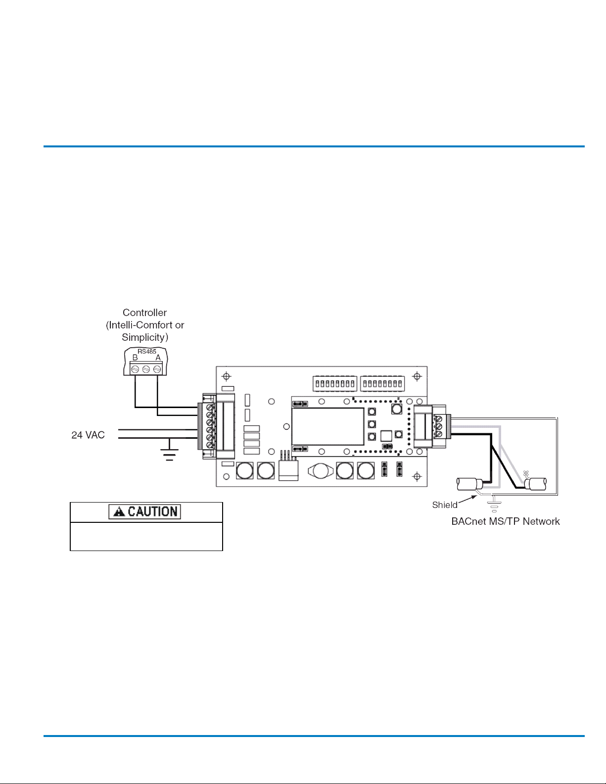
unit and utilizes 24 VAC power from the unit’s control transformer.
One port is connected to the UP controller. The other port must be
connected to the BACnet MS/TP network.
The Simplicity
operational data points from the controller and expose them on a
BACnet MS/TP network.
NOTE: Not all Simplicity
LINC mounts inside the control panel of the UP
®
LINC Gateway is preconfigured to obtain
®
operating parameters are controlled/
monitored by the Simplicity
®
LINC.
R
C
24 — must be grounded
close to the Simplicity LINC
24V power is polarity sensitive, incorrect
wiring could result in board damage.
FIGURE 1: WIRE CONNECTIONS
®
The shield must be
connected to ground at
each device.
1031990-UAD-A-0313
Page 2
1031990-UAD-A-0313
1
0
4
0
16
0
0
0
21
CONNECTION
The Simplicity®LINC has 2 ports, one for connection to the BAS
network (BACnet) and one to the Simplicity
BACNET NETWORK
The only connection required in the field is to the BACnet (BAS)
network.
NOTE: Proper termination and grounding of the shields must
be observed.
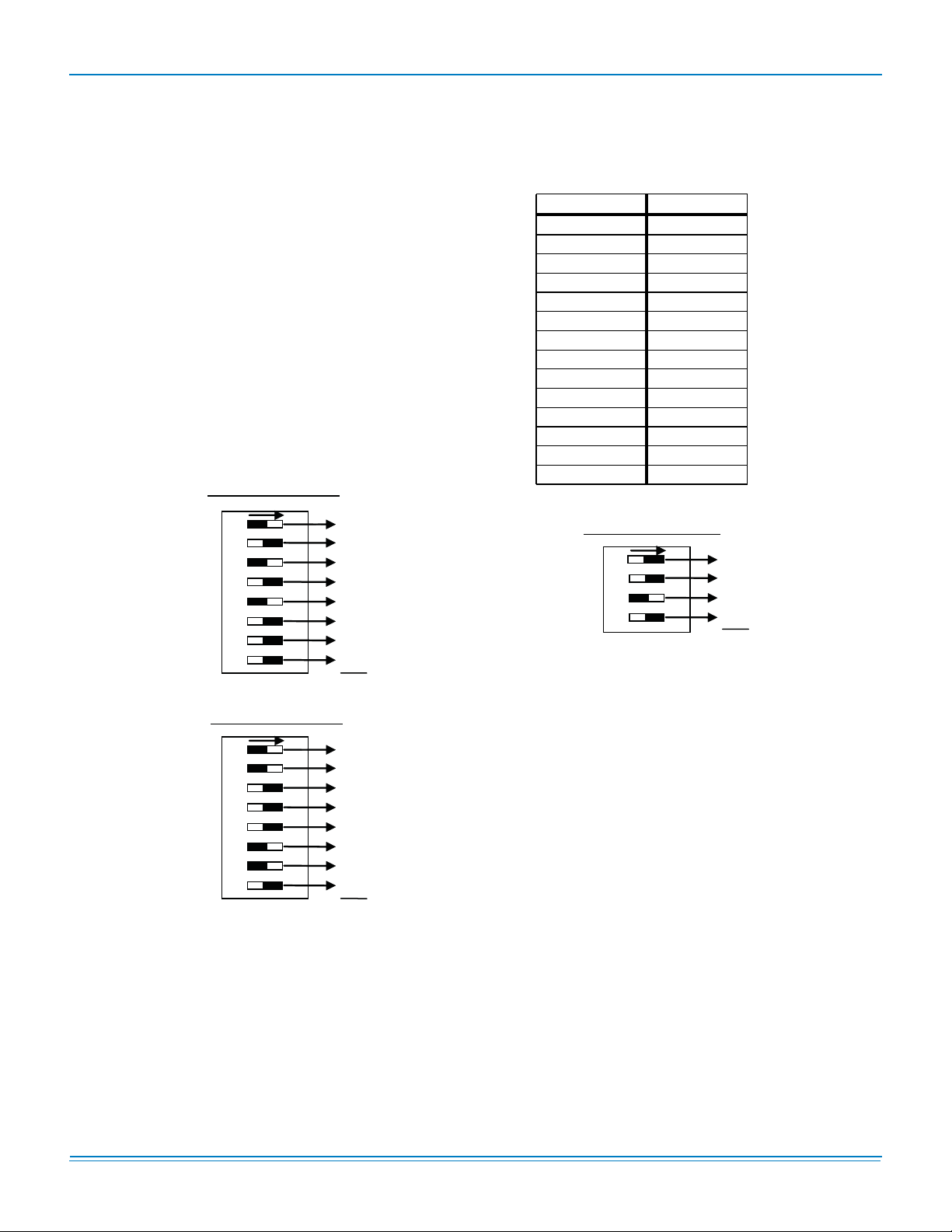
DIP switches A0-A7 on the Simplicity
selection of the MAC Address. The MAC Address identifies the
Simplicity
99. The default DIP switch setting is 1.
A Device Instance (DE) Modifier is used by the Simplicity
and defaulted to 230. The combination of the DE Modifier and
the default DIP switch setting creates a default DE of 23001.
The default Unit Name is YORK_RTU.
®
LINC to other devices and must be between 1 and
MAC Address of 21
1 2 3 4 5 6 7 8
16
32
64
128
1
2
4
8
A0
A1
A2
A3
A4
A5
A6
A7
®
board (Modbus).
®
LINC board allow
ON
®
LINC
DIP switches B0-B3 on the Simplicity
selection of the BACnet transfer speed.The default speed is set
at 38.4k baud. Other speeds can be chosen as shown in Table
1
.
TABLE 1: BAUD RATE SELECTION SETTINGS
®
LINC board allow for
DIP Setting Baud Rate
1 110
2 300
3 600
4 1200
5 2400
6 4800
7 9600
8 19200
9 20833
10 28800
11(Default) 38400
12 57600
13 76800
14 115200
Baud Rate of 38400
B0
B1
B2
B3
1 2 3 4
1
2
4
8
ON
1
2
0
8
11
MAC Address of 99
1 2 3 4 5 6 7 8
16
32
64
128
1
2
4
8
A0
A1
A2
A3
A4
A5
A6
A7
FIGURE 2: MAC ADDRESS EXAMPLES
2 Johnson Controls Unitary Products
ON
1
2
0
0
0
32
64
0
99
Page 3
1031990-UAD-A-0313
MODBUS CONNECTION
The UP device communicates with the Simplicity
the Modbus RTU protocol on an RS485 connection. Connection
and addressing of the UP product is completed at the factory.
No further adjustment should be done.
The default Simplicity® board address is 1 and must
remain on address 1 to correctly communicate with
Simplicity
Com/Setup button 3 times in succession.
If a problem arises with the Simplicity
exposed by the Simplicity
controller software can be manipulated using a Microsoft
Windows-based PC with the Simplicity
(downloadable from the UP website). To connect the PC to the
UP controller, a FREEnet USB adaptor (Part No.
S103101967000), which is an RS232 to RS485 adapter, and
FREEnet adapter cable (S102538682000) are required and
available through SOURCE1 (Toll-free at 1-800-536-6112).
®
LINC. To change the address to 1, press the
®
®
LINC requires modification, the UP
LINC or a parameter not
®
PC software
®
LINC using
©
SOFTWARE SETUP
The control sequence is managed by the Simplicity® controller.
The data points on these systems are mapped to standard
BACnet Objects. As a preconfigured application, no
configuration is necessary in the Simplicity
FLASH MEMORY MANAGEMENT
The Flash Memory chip used in the Simplicity
a 1,000,000 write cycle rating.
To prevent premature failure of the flash memory, it should not
be written to more often than once every 10 minutes, on
average.
Under unusual circumstances it could take up to two
minutes for newly updated data to be seen.
®
LINC Gateway.
®
controllers has
This product has been
tested at a qualified BACnet
testing laboratory and
found to comply with all the
necessary interoperability
requirements.
Johnson Controls Unitary Products 3
Page 4

1031990-UAD-A-0313
TABLE 2: POINTS LIST IN DESCRIPTION ORDER
Read/
Write
BACnet
Object
Type
BACnet
Object
Inst
Descriptor Default Min Max Point Description
R / W (5) BV 109 COMM_IAQ n/a n/a n/a
R / W (5) BV 101 COMM_OAT n/a n/a n/a
R / W (5) BV 100 COMM_OH n/a n/a n/a
R / W (5) BV 99 COMM_RH n/a n/a n/a
R / W (5) BV 108 COMM_ST n/a n/a n/a
R / W (2) AV 14 ACC_OVER_TME n/a n/a n/a
R (2) AI 15 ACTIVE_ALARM n/a n/a n/a
R (2) AI 86 AIR_MON_INPUT 0 0 10
R (5) BI 16 AIR_PROOF_SW n/a n/a n/a
R / W (2) AV 79 OAQ_STPT 1000 0 5000
R (5) BI 85 ALARM_1_ON n/a n/a n/a
R (5) BI 86 ALARM_2_ON n/a n/a n/a
R (5) BI 87 ALARM_3_ON n/a n/a n/a
R (5) BI 88 ALARM_4_ON n/a n/a n/a
R (5) BI 89 ALARM_5_ON n/a n/a n/a
R (2) AI 33 BLDG_STATIC n/a n/a n/a
R / W (5) BV 29 BP_SENS_INST n/a n/a n/a
R / W (2) AV 57 BLDG_SP_STPT 0.15 -0.25 0.25
R / W (2) AV 25 COM_V_LOW_SP 70 60 80
R / W (5) BV 34 CVM_COOLING n/a n/a n/a
R / W (5) BV 35 CVM_HEATING n/a n/a n/a
R (5) BI 33 COM_VENT_STA n/a n/a n/a
R / W (2) AV 24 COM_V_HI_SP 80 65 85
R / W (5) BV 23 COOLING_ENA n/a n/a n/a
R (2) AI 56 CV_VAV_SELEC n/a n/a n/a
R / W (5) BV 21 FAN_ON_W_SEN n/a n/a n/a
R / W (2) AV 8 IAQ_VALUE n/a 0 5000
Accept Comm Value for Indoor Quality
Sensor
Accept Comm Value for OAT
Accept Comm Value for OH
Accept Comm Value for RH
Accept Comm Value for Space
Temperature
Accumulated Unoccupied Override
Time (in hours)
Active Alarm
Air Monitor Station Input
Air Proving Switch Status (1=closed,
0=open / no air flow)
Air Quality Setpoint Outside
Alarm Buffer #1 (0=Alarm has cleared,
1=Alarm is still active)
Alarm Buffer #2 (0=Alarm has cleared,
1=Alarm is still active)
Alarm Buffer #3 (0=Alarm has cleared,
1=Alarm is still active)
Alarm Buffer #4 (0=Alarm has cleared,
1=Alarm is still active)
Alarm Buffer #5 (0=Alarm has cleared,
1=Alarm is still active)
Building Static Pressure
Building Static Pressure Sensor
Installed
Building Static Pressure Setpoint
Comfort Ventilation LowerSetpoint
(degrees F)
Comfort Ventilation Mode for Cooling
Enabled
Comfort Ventilation Mode for Heating
Enabled
Comfort Ventilation Mode Status
(1=control is in Comfort Vent mode, 0= it
is not)
Comfort Ventilation Upper Setpoint
(degrees F)
Cooling Mode Enabled
CV / VAV Selected (0= Valid CV,
1=Valid VAV, 2= Invalid Value)
CV-Indoor Fan Operates with Space
Sensor Present Option Enabled
Demand Ventilation (IAQ) Value (PPM)
4 Johnson Controls Unitary Products
Page 5

TABLE 2: POINTS LIST IN DESCRIPTION ORDER (CONTINUED)
1031990-UAD-A-0313
Read/
Write
BACnet
Object
Type
BACnet
Object
Inst
Descriptor Default Min Max Point Description
R / W (5) BV 39 DEMAND_VENT n/a n/a n/a
R / W (2) AV 18 DEMVENT_STPT 1000 0 5000
R (2) AI 67 REVISION n/a n/a xx
R / W (5) BV 98 DIFF_ENTH_MODE n/a n/a n/a
R / W (5) BV 90 DF_SW_INST n/a n/a n/a
R (5) BI 15 DIRT_FILT_SW n/a n/a n/a
R (2) AI 35 DUCT_STATIC n/a n/a n/a
R / W (2) AV 58 DUCT_SP_STPT 1.5 0 5
R / W (2) AV 59 DUCT_SD_STPT 4.5 0 5
R / W (2) AV 87 ECON_MIN_POS_LP 25 0 100
R (2) AI 31 ECO_DAMP_OUT n/a n/a n/a
R / W (2) AV 20 ECO_1ST_STPT 55 40 65
R / W (5) BV 7 ECONO_INST n/a n/a n/a
R / W (5) BV 36 ECO_L_TO_SAT n/a n/a n/a
R / W (2) AV 19 ECON_MIN_POS 20 0 100
R (5) BI 31 ECONO_STATUS n/a n/a n/a
R / W (2) AV 22 ECON_OAEN_SP 27 10 50
R / W (2) AV 23 ECON_OAT_ENA 55 40 80
R / W (2) AV 84 ECON_RAEN_SP 27 10 50
R / W (2) AV 21 ECO_2ND_STPT 50 40 65
R (2) AI 41 E_C1_ACM_HRS n/a n/a n/a
R (5) BI 42 E_COMP1_STAT n/a n/a n/a
R (5) BI 45 E_C1_OVRLOAD n/a n/a n/a
R (2) AI 42 E_C2_ACM_HRS n/a n/a n/a
R (5) BI 46 E_COMP2_STAT n/a n/a n/a
R (5) BI 49 E_C2_OVRLOAD n/a n/a n/a
R (2) AI 43 E_C3_ACM_HRS n/a n/a n/a
R (5) BI 51 E_COMP3_STAT n/a n/a n/a
Demand Ventilation (using Inside
Sensor) Enabled
Demand Ventilation Setpoint
Device Revision
Differential enthalpy mode enabled
Dirty Filter Switch Installed
Dirty Filter Switch Status
(0=open,1=closed / fault)
Duct Static Pressure
Duct Static Pressure Setpoint
Duct Static Pressure Shutdown Setpoint
Econ Minimum Position For Low Speed
Fan
Economizer Damper Output Status (0-
100%)
Economizer First Stage Setpoint
Economizer Installed
Economizer Loading to Control Supply
Air Temperature Enabled
Economizer Minimum Position
Economizer Output Status (0=not Free
Cooling, 1= Free Cooling)
Economizer Outside Air Enthalpy
Setpoint
Economizer Outside Air Temperature
Enable Setpoint
Economizer Return Air Enthalpy
Setpoint
Economizer Second Stage Setpoint
Elite Compressor #1 Accumulated Run
Time (in hours)
Elite Compressor #1 Output Status
(0=output is OFF, 1=output is ON)
Elite Compressor #1 Overload Switch
Input Status (1=closed, 0=open / fault)
Elite Compressor #2 Accumulated Run
Time (in hours)
Elite Compressor #2 Output Status
(0=output is OFF, 1=output is ON)
Elite Compressor #2 Overload Switch
Input Status (1=closed, 0=open / fault)
Elite Compressor #3 Accumulated Run
Time (in hours)
Elite Compressor #3 Output Status
(0=output is OFF, 1=output is ON)
Johnson Controls Unitary Products 5
Page 6

1031990-UAD-A-0313
TABLE 2: POINTS LIST IN DESCRIPTION ORDER (CONTINUED)
Read/
Write
BACnet
Object
Type
BACnet
Object
Inst
Descriptor Default Min Max Point Description
R (5) BI 54 E_C3_OVRLOAD n/a n/a n/a
R (2) AI 44 E_C4_ACM_HRS n/a n/a n/a
R (5) BI 55 E_ COMP4_STAT n/a n/a n/a
R (5) BI 58 E_C4_OVRLOAD n/a n/a n/a
R (5) BI 50 E_CFAN1_STAT n/a n/a n/a
R (5) BI 59 E_CFAN2_STAT n/a n/a n/a
R (5) BI 41 E_FAN_ OVER n/a n/a n/a
R (5) BI 60 E_GAS_VLVE1 n/a n/a n/a
R (5) BI 62 E_GAS_VLVE2 n/a n/a n/a
R (5) BI 64 E_GAS_VLVE3 n/a n/a n/a
R (5) BI 44 E_HPS1 n/a n/a n/a
R (5) BI 48 E_HPS2 n/a n/a n/a
R (5) BI 53 E_HPS3 n/a n/a n/a
R (5) BI 57 E_HPS4 n/a n/a n/a
R (5) BI 40 E_IFAN_STAT n/a n/a n/a
R (5) BI 61 E_LIMIT_ 1 n/a n/a n/a
R (5) BI 63 E_LIMIT_ 2 n/a n/a n/a
R (5) BI 65 E_LIMIT_ 3 n/a n/a n/a
R (5) BI 43 E_LPS1 n/a n/a n/a
Elite Compressor #3 Overload Switch
Input Status (1=closed, 0=open / fault)
Elite Compressor #4 Accumulated Run
Time (in hours)
Elite Compressor #4 Output Status
(0=output is OFF, 1=output is ON)
Elite Compressor #4 Overload Switch
Input Status (1=closed, 0=open / fault)
Elite Condenser Fan #1 Output Status
(0=output is OFF, 1=output is ON)
Elite Condenser Fan #2 Output Status
Input Status (0=output is OFF, 1=output
is ON)
Elite Fan Overload Switch Input Status
(1=closed, 0=open / fault)
Elite Gas Valve #1 Input Status
(1=energized, 0=not energized)
Elite Gas Valve #2 Input Status
(1=energized, 0=not energized)
Elite Gas Valve #3 Input Status
(1=energized, 0=not energized)
Elite High Pressure Switch for
Compressor #1 Input Status (1=closed,
0=open / fault)
Elite High Pressure Switch for
Compressor #2 Input Status (1=closed,
0=open / fault)
Elite High Pressure Switch for
Compressor #3 Input Status (1=closed,
0=open / fault)
Elite High Pressure Switch for
Compressor #4 Input Status (1=closed,
0=open / fault)
Elite Indoor Fan Output Status
(0=output is OFF, 1=output is ON)
Elite Limit Switch #1 Input Status
(1=closed, 0=open / fault)
Elite Limit Switch #2 Input Status
(1=closed, 0=open / fault)
Elite Limit Switch #3 Input Status
(1=closed, 0=open / fault)
Elite Low Pressure Switch for
Compressor #1 Input Status (1=closed,
0=open / fault)
6 Johnson Controls Unitary Products
Page 7

TABLE 2: POINTS LIST IN DESCRIPTION ORDER (CONTINUED)
1031990-UAD-A-0313
Read/
Write
BACnet
Object
Type
BACnet
Object
Inst
Descriptor Default Min Max Point Description
R (5) BI 47 E_LPS2 n/a n/a n/a
R (5) BI 52 E_LPS3 n/a n/a n/a
R (5) BI 56 E_LPS4 n/a n/a n/a
R (2) AI 32 EXH_DAMP_OUT n/a n/a n/a
R (5) BI 30 EX_FAN_STAT n/a n/a n/a
R / W (5) BV 10 EX_VFD_INST n/a n/a n/a
R / W (2) AV 91 FAN_SPD_1ST_COOL 70 0 100
R / W (2) AV 92 FAN_SPD_1ST_HEAT 100 0 100
R / W (2) AV 93 FAN_SPD_ALL_COOL 100 0 100
R / W (2) AV 94 FAN_SPD_ALL_HEAT 100 0 100
R / W (2) AV 90 FAN_SPD_NO_HEAT_COOL 50 0 100
R (5) BI 102 4_STG_EXP_PRES n/a n/a n/a
R (5) BI 32 FRECOOL_STAT n/a n/a n/a
R (5) BI 104 FREEZE_STAT_1 n/a n/a n/a
R (5) BI 105 FREEZE_STAT_2 n/a n/a n/a
R (5) BI 106 FREEZE_STAT_3 n/a n/a n/a
R (5) BI 107 FREEZE_STAT_4 n/a n/a n/a
R (5) BI 68 HEAT_1_STAT n/a n/a n/a
R (5) BI 69 HEAT_2_STAT n/a n/a n/a
R (5) BI 70 HEAT_3_STAT n/a n/a n/a
R (2) AI 76 H1_ACCUM_HRS n/a n/a n/a
R (2) AI 77 H2_ACCUM_HRS n/a n/a n/a
R (2) AI 78 H3_ACCUM_HRS n/a n/a n/a
R / W (5) BV 25 HEATING_ENA n/a n/a n/a
R / W (2) AV 27 HGR_HUM_STPT 50 0 100
R (5) BI 18 HGR_STAT n/a n/a n/a
Elite Low Pressure Switch for
Compressor #2 Input Status (1=closed,
0=open / fault)
Elite Low Pressure Switch for
Compressor #3 Input Status (1=closed,
0=open / fault)
Elite Low Pressure Switch for
Compressor #4 Input Status (1=closed,
0=open / fault)
Exhaust Damper Output Status (0100%)
Exhaust Fan Output Status (0=output is
OFF, 1=output is ON)
Exhaust VFD Installed
Fan Speed: 1st Stage Cooling
Fan Speed: 1st Stage Heating
Fan Speed: All Stages Cooling
Fan Speed: All Stages Heating
Fan Speed: No Heating No Cooling
Four Stage Expansion board Present
Free Cooling Mode Status (0=comps
not overridden by Econo, 1=comps
overridden)
Freeze Stat # 1
Freeze Stat # 2
Freeze Stat # 3
Freeze Stat # 4
H1 Heating Output #1 Status (0=output
is OFF, 1=output is ON)
H2 Heating Output #2 Status (0=output
is OFF, 1=output is ON)
H3 Heating Output #3 Status (0=output
is OFF, 1=output is ON)
Heating #1 Accumulated Run Time (in
hours)
Heating #2 Accumulated Run Time (in
hours)
Heating #3 Accumulated Run Time (in
hours)
Heating Mode Enabled
Hot Gas Reheat Humidity Setpoint
(percent Humidity)
Hot Gas Reheat Output Status
(0=output is OFF, 1=output is ON)
Johnson Controls Unitary Products 7
Page 8

1031990-UAD-A-0313
TABLE 2: POINTS LIST IN DESCRIPTION ORDER (CONTINUED)
Read/
Write
BACnet
Object
Type
BACnet
Object
Inst
Descriptor Default Min Max Point Description
R (2) AI 47 HGR_VLV_OUT n/a n/a n/a
R (5) BI 66 E_FREEZE_ST n/a n/a n/a
R (2) AI 55 HW_VLV_OUT n/a n/a n/a
R / W (5) BV 2 HYDRONC_HEAT n/a n/a n/a
R / W (5) BV 3 HH_REVER_VLV n/a n/a n/a
R / W (2) AV 62 HYD_S1_SA_SP 120 80 180
R / W (2) AV 63 HYD_S2_SA_SP 150 81 180
R / W (2) AV 80 IO_DVNT_STPT 700 0 2000
R (2) AI 45 I_C1_ACM_HRS n/a n/a n/a
R (5) BI 73 I_COMP1_STAT n/a n/a n/a
R (2) AI 46 I_C2_ACM_HRS n/a n/a n/a
R (5) BI 76 I_COMP2_STAT n/a n/a n/a
R (5) BI 79 I_CFAN_STAT n/a n/a n/a
R (5) BI 72 I_FAN_OVER n/a n/a n/a
R (5) BI 82 I_FREEZE_1 n/a n/a n/a
R (5) BI 83 I_FREEZE_2 n/a n/a n/a
R (5) BI 80 I_GAS_VLVE1 n/a n/a n/a
R (5) BI 75 I_HPS1 n/a n/a n/a
R (5) BI 78 I_HPS2 n/a n/a n/a
R (5) BI 71 I_IFAN_STAT n/a n/a n/a
Hot Gas Reheat Valve Output Status (0100%)
Hot H2O Freeze Thermostat Switch
Input Status (1=closed, 0=open / fault)
Hot Water Valve Output Status (0100%)
Hydronic Heat Enabled
Hydronic Heat Reverse Actuated Valve
Installed
Hydronic Heating Stage #1 Supply Air
Setpoint (degrees F)
Hydronic Heating Stage #2 Supply Air
Setpoint (degrees F)
Indoor / Outdoor Demand Ventilation
Setpoint
Intelli-Comfort Compressor #1
Accumulated Run Time (in hours)
Intelli-Comfort Compressor #1 Input
Status (0=output is OFF, 1=output is
ON)
Intelli-Comfort Compressor #2
Accumulated Run Time (in hours)
Intelli-Comfort Compressor #2 Input
Status (0=output is OFF, 1=output is
ON)
Intelli-Comfort Condenser Fan #1 Input
Status (0=output is OFF, 1=output is
ON)
Intelli-Comfort Fan Overload Switch
Input Status (0=open,1=closed)
Intelli-Comfort Freeze Thermostat
Switch #1 Input Status
(0=open,1=closed)
Intelli-Comfort Freeze Thermostat
Switch #2 Input Status
(0=open,1=closed)
Intelli-Comfort Gas Valve #1 Input
Status
Intelli-Comfort High Pressure Switch for
Compressor #1 Input Status (1=closed,
0=open / fault)
Intelli-Comfort High Pressure Switch for
Compressor #2 Input Status (1=closed,
0=open / fault)
Intelli-Comfort Indoor Fan Output Status
(0=output is OFF, 1=output is ON)
8 Johnson Controls Unitary Products
Page 9

TABLE 2: POINTS LIST IN DESCRIPTION ORDER (CONTINUED)
1031990-UAD-A-0313
Read/
Write
BACnet
Object
Type
BACnet
Object
Inst
Descriptor Default Min Max Point Description
R (5) BI 81 I_LIMIT_1 n/a n/a n/a
R (5) BI 74 I_LPS1 n/a n/a n/a
R (5) BI 77 I_LPS2 n/a n/a n/a
R / W (5) BV 28 INTELLI-STRT n/a n/a n/a
R / W (5) BV 13 LOADSHED n/a n/a n/a
R / W (2) AV 89 LOW_AMB_ECON_MIN 0 0 99
R / W (2) AV 88 LOW_AMB_ECON_STPT 0 0 60
R / W (5) BV 19 LOW_AMB_OVRD n/a n/a n/a
R (5) BI 14 LOW_SUP_VOLT n/a n/a n/a
R / W (2) AV 28 MAX_TH_OFSET 3 0 5
R / W (2) AV 30 MAX_DMV_ECON 50 0 100
R / W (5) BV 110 MIN_AMB_SEN n/a n/a n/a
R / W (2) AV 85 MIN_AMB_TEMP_SP 0 0 100%
R (5) BI 11 MODBUS_ALARM n/a n/a n/a
R / W (5) BV 9 MOD_EX_INST n/a n/a n/a
R / W (2) AV 61 MWU_RAT_STPT 70 50 85
R / W (5) BV 6 MORN_WARM-UP n/a n/a n/a
R (2) AI 16 NUMBER_COMPS 2 4
R (2) AI 48 NUMBER_HEAT n/a n/a n/a
R / W (2) AV 1 OCC_COOL_SP 72 46 99
R / W (2) AV 50 OCC_HEAT_SP 68 45 98
R / W (5) BV 1 OCCUPIED_ENA n/a n/a n/a
R / W (5) BV 93 OCC_COMS_ENA n/a n/a n/a
R (2) AI 17 OP_COOL_STPT n/a n/a n/a
R (2) AI 49 OP_HEAT_STPT 68 45 99
Intelli-Comfort Limit Switch #1 Input
Status
Intelli-Comfort Low Pressure Switch for
Compressor #1 Input Status (1=closed,
0=open / fault)
Intelli-Comfort Low Pressure Switch for
Compressor #2 Input Status (1=closed,
0=open / fault)
Intelli-Start Enabled
Loadshed (0=clear loadshed, 1=set
loadshed operation)
Low Ambient Economizer Minimum
Position (Percent) (0 disables)
Low Ambient Economizer Temperature
Setpoint (0 disables)
Low Ambient Temperature (0=comps
not overridden by LAT, 1=comps
overridden)
Low Supply Voltage (0=comps not
overridden by LSV, 1=comps
overridden)
Max Temperature / Humidity Setpoint
Offset
Maximum Demand Ventillation
Economizer Position
Minimum Outdoor Air Sensor Enabled
Minimum Outdoor Air Temperature
Setpoint (0-100%)
Modbus Communication Alarm
Modulating Exhaust Installed
Morning Warm-Up and VAV Heating:
Return Air Temperature Setpoint
(degrees F)
Morning Warm-Up Enabled
Number of Compressors Available
Number of Heat Stages Available (0,0, 0
stage, 0,1= 1 stage, 1,0= 2 stage, 1,1= 3
stage)
Occupied Cooling Setpoint
Occupied Heating Setpoint
Occupied Input Enabled
Occupied Thermostat or
Communication Input Enabled
Operating Cooling Setpoint
Operating Heating Setpoint
Johnson Controls Unitary Products 9
Page 10

1031990-UAD-A-0313
TABLE 2: POINTS LIST IN DESCRIPTION ORDER (CONTINUED)
Read/
Write
BACnet
Object
Type
BACnet
Object
Inst
Descriptor Default Min Max Point Description
R / W (2) AV 69 OP_STPT_DIF 1 1 5
R / W (2) AV 74 OAT_COOL_L_O 45 0 100
R / W (2) AV 54 OAT_HEAT_L_O 75 0 100
R (2) AI 11 AMB_AIR_ENTH n/a n/a n/a
R / W (2) AV 10 AMB_AIR_HUM n/a n/a n/a
R / W (5) BV 37 OAH_SENSOR n/a n/a n/a
R / W (2) AV 7 AMB_TEMP n/a n/a n/a
R (2) AI 9 OAQ_VALUE n/a 0 5000
R / W (5) BV 8 PWR_EX_INST n/a n/a n/a
R / W (5) BV 20 POP_ENABLED n/a n/a n/a
R / W (2) AV 81 POP_HOURS 4 0 23
R / W (2) AV 82 POP_MINUTES 0 0 59
R (5) BI 17 PURGE_SWITCH n/a n/a n/a
R / W (5) BV 12 REDLINE n/a n/a n/a
R (5) BI 4 REM_CONT_ENA n/a n/a n/a
R / W (5) BV 111 REM_CONT_BAS_ECON n/a n/a n/a
R (2) AI 13 RET_AIR_ENTH n/a n/a n/a
R / W (2) AV 12 RET_AIR_HUM n/a n/a n/a
R (2) AI 5 RET_AIR_TEMP n/a n/a n/a
R / W (5) BV 38 RAH_SENSOR n/a n/a n/a
R / W (2) AV 6 SPACE_TEMP n/a n/a n/a
R / W (2) AV 71 SPCE_ALM_TMP 0 0 25
R / W (2) AV 72 SPCE_ALM_TIM 0 0 120
R / W (5) BV 26 SEN_FAULT_EN n/a n/a n/a
R / W (2) AV 73 SP_OFF_RANGE 3 0 5
R (2) AI 4 SUP_AIR_TEMP n/a n/a n/a
R / W (2) AV 70 SAT_ALM_COOL 0 0 80
R / W (2) AV 53 SAT_ALM_HEAT 0 0 120
R / W (5) BV 22 SAT_COOLING n/a n/a n/a
R / W (2) AV 3 SAT_COOL_SP 50 40 65
Operating Setpoint Differential
Outdoor Air Temperature Cooling
Lockout Temperature
Outdoor Air Temperature
HeatingLockout Temperature
Outside Air Enthalpy
Outside Air Humidity
Outside Air Humidity Sensor Enabled
Outside Air Temperature
Outside Demand Ventilation (OAQ)
Value (PPM)
Power Exhaust Installed
Pre-Occupancy Purge Enabled
Pre-Occupancy Purge Time (hours)
Pre-Occupancy Purge Time (minutes)
Purge Switch Status (0=open,1=closed)
Redline (0=clear redline, 1=set redline
operation)
Remote Control Enabled
Remote Control Third Party BAS
Economizer Enable
Return Air Enthalpy
Return Air Humidity
Return Air Temperature
Return/Inside Air Humidity Sensor
Enabled
Space (Indoor) Air Temperature
Space Sensor Alarm Temperature
(degrees F, 0 = disabled)
Space Sensor Alarm Time (minutes F, 0
= disabled)
Space Sensor Fault Override
(Construction Mode) Enabled
Space Temprature Sensor Offset Range
(0-5 degrees)
Supply Air Temperature
Supply Air Temperature Alarm Setpoint
for Cooling
Supply Air Temperature Alarm Setpoint
for Heating
Supply Air Temperature Limit for
Cooling Enabled
Supply Air Temperature Limit for
Cooling Setpoint (degrees F)
10 Johnson Controls Unitary Products
Page 11

TABLE 2: POINTS LIST IN DESCRIPTION ORDER (CONTINUED)
1031990-UAD-A-0313
Read/
Write
BACnet
Object
Type
BACnet
Object
Inst
Descriptor Default Min Max Point Description
R / W (5) BV 24 SAT_HEATING n/a n/a n/a
R / W (2) AV 52 SAT_HEAT_SP 135 100 180
R (2) AI 34 SFAN_VFD_OUT n/a n/a n/a
R (2) AI 36 ALARM_1 n/a n/a n/a
R (2) AI 37 ALARM_2 n/a n/a n/a
R (2) AI 38 ALARM_3 n/a n/a n/a
R (2) AI 39 ALARM_4 n/a n/a n/a
R (2) AI 40 ALARM_5 n/a n/a n/a
R / W (2) AV 29 TH_OFFSET 5 1 10
R / W (2) AV 26 TEM_HUM_STPT 50 20 80
R / W (5) BV 97 THERMO_CONTROL n/a n/a n/a
R / W (5) BV 67 FAN_HEAT n/a n/a n/a
R / W (2) AV 2 UNOC_COOL_SP 85 46 99
R / W (2) AV 51 UNOC_HEAT_SP 60 45 98
R / W (2) AV 75 UNOC_OVR_TP 60 0 240
R (5) BI 103 VAV_INTELLI_2_PRES n/a n/a n/a
R / W (2) AV 65 VAV_CL_LO_SP 55 40 69
R / W (2) AV 66 VAV_SAT_RSET 72 40 85
R / W (2) AV 64 VAV_CL_HI_SP 60 41 70
R / W (5) BV 5 VAV_OCC_HEAT n/a n/a n/a
R / W (2) AV 60 VAV_OHEAT_SP 68 40 85
R / W (5) BV 96 VAV_UNOCC_HEAT n/a n/a n/a
Supply Air Temperature Limit for
Heating Enabled
Supply Air Temperature Limit for
Heating Setpoint (degrees F)
Supply Fan VFD Output Status (0100%)
System Alarm #1
System Alarm #2
System Alarm #3
System Alarm #4
System Alarm #5
Temperature / Humidity % Humidity that
= 1°F of Offset
Temperature / Humidity Setpoint
(percent Humidity)
Thermostat Only Control Enable
Turn OFF Continuous Fan when
Starting Heat Enabled (0=Continuous
Fan ON)
Un-Occupied Cooling Setpoint
Un-Occupied Heating Setpoint
Unoccupied Override Time Period
VAV / Intelli-Comfort 2 Expansion Board
Present
VAV Cooling Supply Air Temperature:
Lower Setpoint (degrees F)
VAV Cooling Supply Air Temperature:
Reset Setpoint (Space
Temperature)(degrees F)
VAV Cooling Supply Air Temperature:
Upper Setpoint (degrees F)
VAV Occupied Heating Enabled
VAV Occupied Heating Setpoint
(degrees F)
VAV Unoccupied Heating Enabled
Johnson Controls Unitary Products 11
Page 12

1031990-UAD-A-0313
TABLE 3: POINTS LIST IN OBJECT ORDER
Read/
Write
BACnet
Object
Type
BACnet
Object
Inst
Descriptor Default Min Max Point Description
R / W (2) AV 1 OCC_COOL_SP 72 46 99
R / W (2) AV 2 UNOC_COOL_SP 85 46 99
R / W (2) AV 3 SAT_COOL_SP 50 40 65
R (2) AI 4 SUP_AIR_TEMP n/a n/a n/a
R (2) AI 5 RET_AIR_TEMP n/a n/a n/a
R / W (2) AV 6 SPACE_TEMP n/a n/a n/a
R / W (2) AV 7 AMB_TEMP n/a n/a n/a
R / W (2) AV 8 IAQ_VALUE n/a 0 5000
R (2) AI 9 OAQ_VALUE n/a 0 5000
R / W (2) AV 10 AMB_AIR_HUM n/a n/a n/a
R (2) AI 11 AMB_AIR_ENTH n/a n/a n/a
R / W (2) AV 12 RET_AIR_HUM n/a n/a n/a
R (2) AI 13 RET_AIR_ENTH n/a n/a n/a
R / W (2) AV 14 ACC_OVER_TME n/a n/a n/a
R (2) AI 15 ACTIVE_ALARM n/a n/a n/a
R (2) AI 16 NUMBER_COMPS 2 4
R (2) AI 17 OP_COOL_STPT n/a n/a n/a
R / W (2) AV 18 DEMVENT_STPT 1000 0 5000
R / W (2) AV 19 ECON_MIN_POS 20 0 100
R / W (2) AV 20 ECO_1ST_STPT 55 40 65
R / W (2) AV 21 ECO_2ND_STPT 50 40 65
R / W (2) AV 22 ECON_OAEN_SP 27 10 50
R / W (2) AV 23 ECON_OAT_ENA 55 40 80
R / W (2) AV 24 COM_V_HI_SP 80 65 85
R / W (2) AV 25 COM_V_LOW_SP 70 60 80
R / W (2) AV 26 TEM_HUM_STPT 50 20 80
R / W (2) AV 27 HGR_HUM_STPT 50 0 100
R / W (2) AV 28 MAX_TH_OFSET 3 0 5
Occupied Cooling Setpoint
Un-Occupied Cooling Setpoint
Supply Air Temperature Limit for
Cooling Setpoint (degrees F)
Supply Air Temperature
Return Air Temperature
Space (Indoor) Air Temperature
Outside Air Temperature
Demand Ventilation (IAQ) Value (PPM)
Outside Demand Ventilation (OAQ)
Value (PPM)
Outside Air Humidity
Outside Air Enthalpy
Return Air Humidity
Return Air Enthalpy
Accumulated Unoccupied Override
Time (in hours)
Active Alarm
Number of Compressors Available
Operating Cooling Setpoint
Demand Ventilation Setpoint
Economizer Minimum Position
Economizer First Stage Setpoint
Economizer Second Stage Setpoint
Economizer Outside Air Enthalpy
Setpoint
Economizer Outside Air Temperature
Enable Setpoint
Comfort Ventilation Upper Setpoint
(degrees F)
Comfort Ventilation LowerSetpoint
(degrees F)
Temperature / Humidity Setpoint
(percent Humidity)
Hot Gas Reheat Humidity Setpoint
(percent Humidity)
Max Temperature / Humidity Setpoint
Offset
12 Johnson Controls Unitary Products
Page 13

TABLE 3: POINTS LIST IN OBJECT ORDER (CONTINUED)
1031990-UAD-A-0313
Read/
Write
BACnet
Object
Type
BACnet
Object
Inst
Descriptor Default Min Max Point Description
R / W (2) AV 29 TH_OFFSET 5 1 10
R / W (2) AV 30 MAX_DMV_ECON 50 0 100
R (2) AI 31 ECO_DAMP_OUT n/a n/a n/a
R (2) AI 32 EXH_DAMP_OUT n/a n/a n/a
R (2) AI 33 BLDG_STATIC n/a n/a n/a
R (2) AI 34 SFAN_VFD_OUT n/a n/a n/a
R (2) AI 35 DUCT_STATIC n/a n/a n/a
R (2) AI 36 ALARM_1 n/a n/a n/a
R (2) AI 37 ALARM_2 n/a n/a n/a
R (2) AI 38 ALARM_3 n/a n/a n/a
R (2) AI 39 ALARM_4 n/a n/a n/a
R (2) AI 40 ALARM_5 n/a n/a n/a
R (2) AI 41 E_C1_ACM_HRS n/a n/a n/a
R (2) AI 42 E_C2_ACM_HRS n/a n/a n/a
R (2) AI 43 E_C3_ACM_HRS n/a n/a n/a
R (2) AI 44 E_C4_ACM_HRS n/a n/a n/a
R (2) AI 45 I_C1_ACM_HRS n/a n/a n/a
R (2) AI 46 I_C2_ACM_HRS n/a n/a n/a
R (2) AI 47 HGR_VLV_OUT n/a n/a n/a
R (2) AI 48 NUMBER_HEAT n/a n/a n/a
R (2) AI 49 OP_HEAT_STPT 68 45 99
R / W
R / W
R / W
R / W
(2) AV
(2) AV
(2) AV
(2) AV
50 OCC_HEAT_SP 68 45 98 Occupied Heating Setpoint
51 UNOC_HEAT_SP 60 45 98 Un-Occupied Heating Setpoint
52 SAT_HEAT_SP 135 100 180 Supply Air Temperature Limit for
53 SAT_ALM_HEAT 0 0 120 Supply Air Temperature Alarm
Temperature / Humidity % Humidity
that = 1°F of Offset
Maximum Demand Ventillation
Economizer Position
Economizer Damper Output Status (0100%)
Exhaust Damper Output Status (0100%)
Building Static Pressure
Supply Fan VFD Output Status (0-
100%)
Duct Static Pressure
System Alarm #1
System Alarm #2
System Alarm #3
System Alarm #4
System Alarm #5
Elite Compressor #1 Accumulated Run
Time (in hours)
Elite Compressor #2 Accumulated Run
Time (in hours)
Elite Compressor #3 Accumulated Run
Time (in hours)
Elite Compressor #4 Accumulated Run
Time (in hours)
Intelli-Comfort Compressor #1
Accumulated Run Time (in hours)
Intelli-Comfort Compressor #2
Accumulated Run Time (in hours)
Hot Gas Reheat Valve Output Status
(0-100%)
Number of Heat Stages Available (0,0,
0 stage, 0,1= 1 stage, 1,0= 2 stage,
1,1= 3 stage)
Operating Heating Setpoint
Heating Setpoint (degrees F)
Setpoint for Heating
Johnson Controls Unitary Products 13
Page 14

1031990-UAD-A-0313
TABLE 3: POINTS LIST IN OBJECT ORDER (CONTINUED)
Read/
Write
R / W
R
R
R / W
R / W
R / W
R / W
R / W
R / W
R / W
R / W
R / W
R / W
R
R / W
R / W
R / W
R / W
R / W
R / W
R / W
R
BACnet
Object
Type
(2) AV
(2) AI
(2) AI
(2) AV
(2) AV
(2) AV
(2) AV
(2) AV
(2) AV
(2) AV
(2) AV
(2) AV
(2) AV
(2) AI
(2) AV
(2) AV
(2) AV
(2) AV
(2) AV
(2) AV
(2) AV
(2) AI
BACnet
Object
Descriptor Default Min Max Point Description
Inst
54 OAT_HEAT_L_O 75 0 100 Outdoor Air Temperature
HeatingLockout Temperature
55 HW_VLV_OUT n/a n/a n/a Hot Water Valve Output Status (0-
100%)
56 CV_VAV_SELEC n/a n/a n/a CV / VAV Selected (0= Valid CV,
1=Valid VAV, 2= Invalid Value)
57 BLDG_SP_STPT 0.15 -0.25 0.25 Building Static Pressure Setpoint
58 DUCT_SP_STPT 1.5 0 5 Duct Static Pressure Setpoint
59 DUCT_SD_STPT 4.5 0 5 Duct Static Pressure Shutdown
Setpoint
60 VAV_OHEAT_SP 68 40 85 VAV Occupied Heating Setpoint
(degrees F)
61 MWU_RAT_STPT 70 50 85 Morning Warm-Up and VAV Heating:
Return Air Temperature Setpoint
(degrees F)
62 HYD_S1_SA_SP 120 80 180 Hydronic Heating Stage #1 Supply Air
Setpoint (degrees F)
63 HYD_S2_SA_SP 150 81 180 Hydronic Heating Stage #2 Supply Air
Setpoint (degrees F)
64 VAV_CL_HI_SP 60 41 70 VAV Cooling Supply Air Temperature:
Upper Setpoint (degrees F)
65 VAV_CL_LO_SP 55 40 69 VAV Cooling Supply Air Temperature:
Lower Setpoint (degrees F)
66 VAV_SAT_RSET 72 40 85 VAV Cooling Supply Air Temperature:
Reset Setpoint (Space
Temperature)(degrees F)
67 REVISION n/a n/a xx Device Revision
69 OP_STPT_DIF 1 1 5 Operating Setpoint Differential
70 SAT_ALM_COOL 0 0 80 Supply Air Temperature Alarm
Setpoint for Cooling
71 SPCE_ALM_TMP 0 0 25 Space Sensor Alarm Temperature
(degrees F, 0 = disabled)
72 SPCE_ALM_TIM 0 0 120 Space Sensor Alarm Time (minutes F,
0 = disabled)
73 SP_OFF_RANGE 3 0 5 Space Temprature Sensor Offset
Range (0-5 degrees)
74 OAT_COOL_L_O 45 0 100 Outdoor Air Temperature Cooling
Lockout Temperature
75 UNOC_OVR_TP 60 0 240 Unoccupied Override Time Period
76 H1_ACCUM_HRS n/a n/a n/a Heating #1 Accumulated Run Time (in
hours)
14 Johnson Controls Unitary Products
Page 15

TABLE 3: POINTS LIST IN OBJECT ORDER (CONTINUED)
1031990-UAD-A-0313
Read/
Write
R
R
R / W
R / W
R / W
R / W
R / W
R / W
R
R / W
R / W
R / W
R / W
R / W
R / W
R / W
R / W
R / W (5) BV 1 OCCUPIED_ENA n/a n/a n/a Occupied Input Enabled
R / W (5) BV 2 HYDRONC_HEAT n/a n/a n/a Hydronic Heat Enabled
R / W (5) BV 3 HH_REVER_VLV n/a n/a n/a Hydronic Heat Reverse Actuated Valve
R (5) BI 4 REM_CONT_ENA n/a n/a n/a Remote Control Enabled
R / W (5) BV 5 VAV_OCC_HEAT n/a n/a n/a VAV Occupied Heating Enabled
R / W (5) BV 6 MORN_WARM-UP n/a n/a n/a Morning Warm-Up Enabled
R / W (5) BV 7 ECONO_INST n/a n/a n/a Economizer Installed
R / W (5) BV 8 PWR_EX_INST n/a n/a n/a Power Exhaust Installed
R / W (5) BV 9 MOD_EX_INST n/a n/a n/a Modulating Exhaust Installed
R / W (5) BV 10 EX_VFD_INST n/a n/a n/a Exhaust VFD Installed
R (5) BI 11 MODBUS_ALARM n/a n/a n/a Modbus Communication Alarm
BACnet
Object
Type
(2) AI
(2) AI
(2) AV
(2) AV
(2) AV
(2) AV
(2) AV
(2) AV
(2) AI
(2) AV
(2) AV
(2) AV
(2) AV
(2) AV
(2) AV
(2) AV
(2) AV
BACnet
Object
Descriptor Default Min Max Point Description
Inst
77 H2_ACCUM_HRS n/a n/a n/a Heating #2 Accumulated Run Time (in
hours)
78 H3_ACCUM_HRS n/a n/a n/a Heating #3 Accumulated Run Time (in
hours)
79 OAQ_STPT 1000 0 5000 Air Quality Setpoint Outside
80 IO_DVNT_STPT 700 0 2000 Indoor / Outdoor Demand Ventilation
Setpoint
81 POP_HOURS 4 0 23 Pre-Occupancy Purge Time (hours)
82 POP_MINUTES 0 0 59 Pre-Occupancy Purge Time (minutes)
84 ECON_RAEN_SP 27 10 50 Economizer Return Air Enthalpy
Setpoint
85 MIN_AMB_TEMP_SP 0 0 100% Minimum Outdoor Air Temperature
Setpoint (0-100%)
86 AIR_MON_INPUT 0 0 10 Air Monitor Station Input
87 ECON_MIN_POS_LP 25 0 100 Econ Minimum Position For Low
Speed Fan
88 LOW_AMB_ECON_STP
T
89 LOW_AMB_ECON_MIN 0 0 99 Low Ambient Economizer Minimum
90 FAN_SPD_NO_HEAT_C
OOL
91 FAN_SPD_1ST_COOL 70 0 100 Fan Speed: 1st Stage Cooling
92 FAN_SPD_1ST_HEAT 100 0 100 Fan Speed: 1st Stage Heating
93 FAN_SPD_ALL_COOL 100 0 100 Fan Speed: All Stages Cooling
94 FAN_SPD_ALL_HEAT 100 0 100 Fan Speed: All Stages Heating
0 0 60 Low Ambient Economizer Temperature
Setpoint (0 disables)
Position (Percent) (0 disables)
50 0 100 Fan Speed: No Heating No Cooling
Installed
Johnson Controls Unitary Products 15
Page 16

1031990-UAD-A-0313
TABLE 3: POINTS LIST IN OBJECT ORDER (CONTINUED)
Read/
Write
R / W (5) BV 12 REDLINE n/a n/a n/a Redline (0=clear redline, 1=set redline
R / W (5) BV 13 LOADSHED n/a n/a n/a Loadshed (0=clear loadshed, 1=set
R (5) BI 14 LOW_SUP_VOLT n/a n/a n/a Low Supply Voltage (0=comps not
R (5) BI 15 DIRT_FILT_SW n/a n/a n/a Dirty Filter Switch Status
R (5) BI 16 AIR_PROOF_SW n/a n/a n/a Air Proving Switch Status (1=closed,
R (5) BI 17 PURGE_SWITCH n/a n/a n/a Purge Switch Status
R (5) BI 18 HGR_STAT n/a n/a n/a Hot Gas Reheat Output Status
R / W (5) BV 19 LOW_AMB_OVRD n/a n/a n/a Low Ambient Temperature (0=comps
R / W (5) BV 20 POP_ENABLED n/a n/a n/a Pre-Occupancy Purge Enabled
R / W (5) BV 21 FAN_ON_W_SEN n/a n/a n/a CV-Indoor Fan Operates with Space
R / W (5) BV 22 SAT_COOLING n/a n/a n/a Supply Air Temperature Limit for
R / W (5) BV 23 COOLING_ENA n/a n/a n/a Cooling Mode Enabled
R / W (5) BV 24 SAT_HEATING n/a n/a n/a Supply Air Temperature Limit for
R / W (5) BV 25 HEATING_ENA n/a n/a n/a Heating Mode Enabled
R / W (5) BV 26 SEN_FAULT_EN n/a n/a n/a Space Sensor Fault Override
R / W (5) BV 28 INTELLI-STRT n/a n/a n/a Intelli-Start Enabled
R / W (5) BV 29 BP_SENS_INST n/a n/a n/a Building Static Pressure Sensor
R (5) BI 30 EX_FAN_STAT n/a n/a n/a Exhaust Fan Output Status (0=output
R (5) BI 31 ECONO_STATUS n/a n/a n/a Economizer Output Status (0=not Free
R (5) BI 32 FRECOOL_STAT n/a n/a n/a Free Cooling Mode Status (0=comps
R (5) BI 33 COM_VENT_STA n/a n/a n/a Comfort Ventilation Mode Status
BACnet
Object
Type
BACnet
Object
Inst
Descriptor Default Min Max Point Description
operation)
loadshed operation)
overridden by LSV, 1=comps
overridden)
(0=open,1=closed / fault)
0=open / no air flow)
(0=open,1=closed)
(0=output is OFF, 1=output is ON)
not overridden by LAT, 1=comps
overridden)
Sensor Present Option Enabled
Cooling Enabled
Heating Enabled
(Construction Mode) Enabled
Installed
is OFF, 1=output is ON)
Cooling, 1= Free Cooling)
not overridden by Econo, 1=comps
overridden)
(1=control is in Comfort Vent mode, 0=
it is not)
16 Johnson Controls Unitary Products
Page 17

TABLE 3: POINTS LIST IN OBJECT ORDER (CONTINUED)
1031990-UAD-A-0313
Read/
Write
R / W (5) BV 34 CVM_COOLING n/a n/a n/a Comfort Ventilation Mode for Cooling
R / W (5) BV 35 CVM_HEATING n/a n/a n/a Comfort Ventilation Mode for Heating
R / W (5) BV 36 ECO_L_TO_SAT n/a n/a n/a Economizer Loading to Control Supply
R / W (5) BV 37 OAH_SENSOR n/a n/a n/a Outside Air Humidity Sensor Enabled
R / W (5) BV 38 RAH_SENSOR n/a n/a n/a Return/Inside Air Humidity Sensor
R / W (5) BV 39 DEMAND_VENT n/a n/a n/a Demand Ventilation (using Inside
R (5) BI 40 E_IFAN_STAT n/a n/a n/a Elite Indoor Fan Output Status
R (5) BI 41 E_FAN_ OVER n/a n/a n/a Elite Fan Overload Switch Input Status
R (5) BI 42 E_COMP1_STAT n/a n/a n/a Elite Compressor #1 Output Status
R (5) BI 43 E_LPS1 n/a n/a n/a Elite Low Pressure Switch for
R (5) BI 44 E_HPS1 n/a n/a n/a Elite High Pressure Switch for
R (5) BI 45 E_C1_OVRLOAD n/a n/a n/a Elite Compressor #1 Overload Switch
R (5) BI 46 E_COMP2_STAT n/a n/a n/a Elite Compressor #2 Output Status
R (5) BI 47 E_LPS2 n/a n/a n/a Elite Low Pressure Switch for
R (5) BI 48 E_HPS2 n/a n/a n/a Elite High Pressure Switch for
R (5) BI 49 E_C2_OVRLOAD n/a n/a n/a Elite Compressor #2 Overload Switch
R (5) BI 50 E_CFAN1_STAT n/a n/a n/a Elite Condenser Fan #1 Output Status
R (5) BI 51 E_COMP3_STAT n/a n/a n/a Elite Compressor #3 Output Status
R (5) BI 52 E_LPS3 n/a n/a n/a Elite Low Pressure Switch for
BACnet
Object
Type
BACnet
Object
Inst
Descriptor Default Min Max Point Description
Enabled
Enabled
Air Temperature Enabled
Enabled
Sensor) Enabled
(0=output is OFF, 1=output is ON)
(1=closed, 0=open / fault)
(0=output is OFF, 1=output is ON)
Compressor #1 Input Status (1=closed,
0=open / fault)
Compressor #1 Input Status (1=closed,
0=open / fault)
Input Status (1=closed, 0=open / fault)
(0=output is OFF, 1=output is ON)
Compressor #2 Input Status (1=closed,
0=open / fault)
Compressor #2 Input Status (1=closed,
0=open / fault)
Input Status (1=closed, 0=open / fault)
(0=output is OFF, 1=output is ON)
(0=output is OFF, 1=output is ON)
Compressor #3 Input Status (1=closed,
0=open / fault)
Johnson Controls Unitary Products 17
Page 18

1031990-UAD-A-0313
TABLE 3: POINTS LIST IN OBJECT ORDER (CONTINUED)
Read/
Write
R (5) BI 53 E_HPS3 n/a n/a n/a Elite High Pressure Switch for
R (5) BI 54 E_C3_OVRLOAD n/a n/a n/a Elite Compressor #3 Overload Switch
R (5) BI 55 E_ COMP4_STAT n/a n/a n/a Elite Compressor #4 Output Status
R (5) BI 56 E_LPS4 n/a n/a n/a Elite Low Pressure Switch for
R (5) BI 57 E_HPS4 n/a n/a n/a Elite High Pressure Switch for
R (5) BI 58 E_C4_OVRLOAD n/a n/a n/a Elite Compressor #4 Overload Switch
R (5) BI 59 E_CFAN2_STAT n/a n/a n/a Elite Condenser Fan #2 Output Status
R (5) BI 60 E_GAS_VLVE1 n/a n/a n/a Elite Gas Valve #1 Input Status
R (5) BI 61 E_LIMIT_ 1 n/a n/a n/a Elite Limit Switch #1 Input Status
R (5) BI 62 E_GAS_VLVE2 n/a n/a n/a Elite Gas Valve #2 Input Status
R (5) BI 63 E_LIMIT_ 2 n/a n/a n/a Elite Limit Switch #2 Input Status
R (5) BI 64 E_GAS_VLVE3 n/a n/a n/a Elite Gas Valve #3 Input Status
R (5) BI 65 E_LIMIT_ 3 n/a n/a n/a Elite Limit Switch #3 Input Status
R (5) BI 66 E_FREEZE_ST n/a n/a n/a Hot H2O Freeze Thermostat Switch
R / W (5) BV 67 FAN_HEAT n/a n/a n/a Turn OFF Continuous Fan when
R (5) BI 68 HEAT_1_STAT n/a n/a n/a H1 Heating Output #1 Status (0=output
R (5) BI 69 HEAT_2_STAT n/a n/a n/a H2 Heating Output #2 Status (0=output
R (5) BI 70 HEAT_3_STAT n/a n/a n/a H3 Heating Output #3 Status (0=output
BACnet
Object
Type
BACnet
Object
Inst
Descriptor Default Min Max Point Description
Compressor #3 Input Status (1=closed,
0=open / fault)
Input Status (1=closed, 0=open / fault)
(0=output is OFF, 1=output is ON)
Compressor #4 Input Status (1=closed,
0=open / fault)
Compressor #4 Input Status (1=closed,
0=open / fault)
Input Status (1=closed, 0=open / fault)
Input Status (0=output is OFF,
1=output is ON)
(1=energized, 0=not energized)
(1=closed, 0=open / fault)
(1=energized, 0=not energized)
(1=closed, 0=open / fault)
(1=energized, 0=not energized)
(1=closed, 0=open / fault)
Input Status (1=closed, 0=open / fault)
Starting Heat Enabled (0=Continuous
Fan ON)
is OFF, 1=output is ON)
is OFF, 1=output is ON)
is OFF, 1=output is ON)
18 Johnson Controls Unitary Products
Page 19

TABLE 3: POINTS LIST IN OBJECT ORDER (CONTINUED)
1031990-UAD-A-0313
Read/
Write
R (5) BI 71 I_IFAN_STAT n/a n/a n/a Intelli-Comfort Indoor Fan Output
R (5) BI 72 I_FAN_OVER n/a n/a n/a Intelli-Comfort Fan Overload Switch
R (5) BI 73 I_COMP1_STAT n/a n/a n/a Intelli-Comfort Compressor #1 Input
R (5) BI 74 I_LPS1 n/a n/a n/a Intelli-Comfort Low Pressure Switch for
R (5) BI 75 I_HPS1 n/a n/a n/a Intelli-Comfort High Pressure Switch
R (5) BI 76 I_COMP2_STAT n/a n/a n/a Intelli-Comfort Compressor #2 Input
R (5) BI 77 I_LPS2 n/a n/a n/a Intelli-Comfort Low Pressure Switch for
R (5) BI 78 I_HPS2 n/a n/a n/a Intelli-Comfort High Pressure Switch
R (5) BI 79 I_CFAN_STAT n/a n/a n/a Intelli-Comfort Condenser Fan #1 Input
R (5) BI 80 I_GAS_VLVE1 n/a n/a n/a Intelli-Comfort Gas Valve #1 Input
R (5) BI 81 I_LIMIT_1 n/a n/a n/a Intelli-Comfort Limit Switch #1 Input
R (5) BI 82 I_FREEZE_1 n/a n/a n/a Intelli-Comfort Freeze Thermostat
R (5) BI 83 I_FREEZE_2 n/a n/a n/a Intelli-Comfort Freeze Thermostat
R (5) BI 85 ALARM_1_ON n/a n/a n/a Alarm Buffer #1 (0=Alarm has cleared,
R (5) BI 86 ALARM_2_ON n/a n/a n/a Alarm Buffer #2 (0=Alarm has cleared,
R (5) BI 87 ALARM_3_ON n/a n/a n/a Alarm Buffer #3 (0=Alarm has cleared,
R (5) BI 88 ALARM_4_ON n/a n/a n/a Alarm Buffer #4 (0=Alarm has cleared,
BACnet
Object
Type
BACnet
Object
Inst
Descriptor Default Min Max Point Description
Status (0=output is OFF, 1=output is
ON)
Input Status (0=open,1=closed)
Status (0=output is OFF, 1=output is
ON)
Compressor #1 Input Status (1=closed,
0=open / fault)
for Compressor #1 Input Status
(1=closed, 0=open / fault)
Status (0=output is OFF, 1=output is
ON)
Compressor #2 Input Status (1=closed,
0=open / fault)
for Compressor #2 Input Status
(1=closed, 0=open / fault)
Status (0=output is OFF, 1=output is
ON)
Status
Status
Switch #1 Input Status
(0=open,1=closed)
Switch #2 Input Status
(0=open,1=closed)
1=Alarm is still active)
1=Alarm is still active)
1=Alarm is still active)
1=Alarm is still active)
Johnson Controls Unitary Products 19
Page 20

1031990-UAD-A-0313
TABLE 3: POINTS LIST IN OBJECT ORDER (CONTINUED)
Read/
Write
R (5) BI 89 ALARM_5_ON n/a n/a n/a Alarm Buffer #5 (0=Alarm has cleared,
R / W (5) BV 90 DF_SW_INST n/a n/a n/a Dirty Filter Switch Installed
R / W (5) BV 93 OCC_COMS_ENA n/a n/a n/a Occupied Thermostat or
R / W (5) BV 96 VAV_UNOCC_HEAT n/a n/a n/a VAV Unoccupied Heating Enabled
R / W (5) BV 97 THERMO_CONTROL n/a n/a n/a Thermostat Only Control Enable
R / W (5) BV 98 DIFF_ENTH_MODE n/a n/a n/a Differential enthalpy mode enabled
R / W (5) BV 99 COMM_RH n/a n/a n/a Accept Comm Value for RH
R / W (5) BV 100 COMM_OH n/a n/a n/a Accept Comm Value for OH
R / W (5) BV 101 COMM_OAT n/a n/a n/a Accept Comm Value for OAT
R (5) BI 102 4_STG_EXP_PRES n/a n/a n/a Four Stage Expansion board Present
R (5) BI 103 VAV_INTELLI_2_PRES n/a n/a n/a VAV / Intelli-Comfort 2 Expansion
R (5) BI 104 FREEZE_STAT_1 n/a n/a n/a Freeze Stat # 1
R (5) BI 105 FREEZE_STAT_2 n/a n/a n/a Freeze Stat # 2
R (5) BI 106 FREEZE_STAT_3 n/a n/a n/a Freeze Stat # 3
R (5) BI 107 FREEZE_STAT_4 n/a n/a n/a Freeze Stat # 4
R / W (5) BV 108 COMM_ST n/a n/a n/a Accept Comm Value for Space
R / W (5) BV 109 COMM_IAQ n/a n/a n/a Accept Comm Value for Indoor Quality
R / W (5) BV 110 MIN_AMB_SEN n/a n/a n/a Minimum Outdoor Air Sensor Enabled
R / W (5) BV 111 REM_CONT_BAS_ECO
BACnet
Object
Type
BACnet
Object
Inst
Descriptor Default Min Max Point Description
1=Alarm is still active)
Communication Input Enabled
Board Present
Temperature
Sensor
n/a n/a n/a Remote Control Third Party BAS
N
Economizer Enable
20 Johnson Controls Unitary Products
Page 21

TROUBLESHOOTING
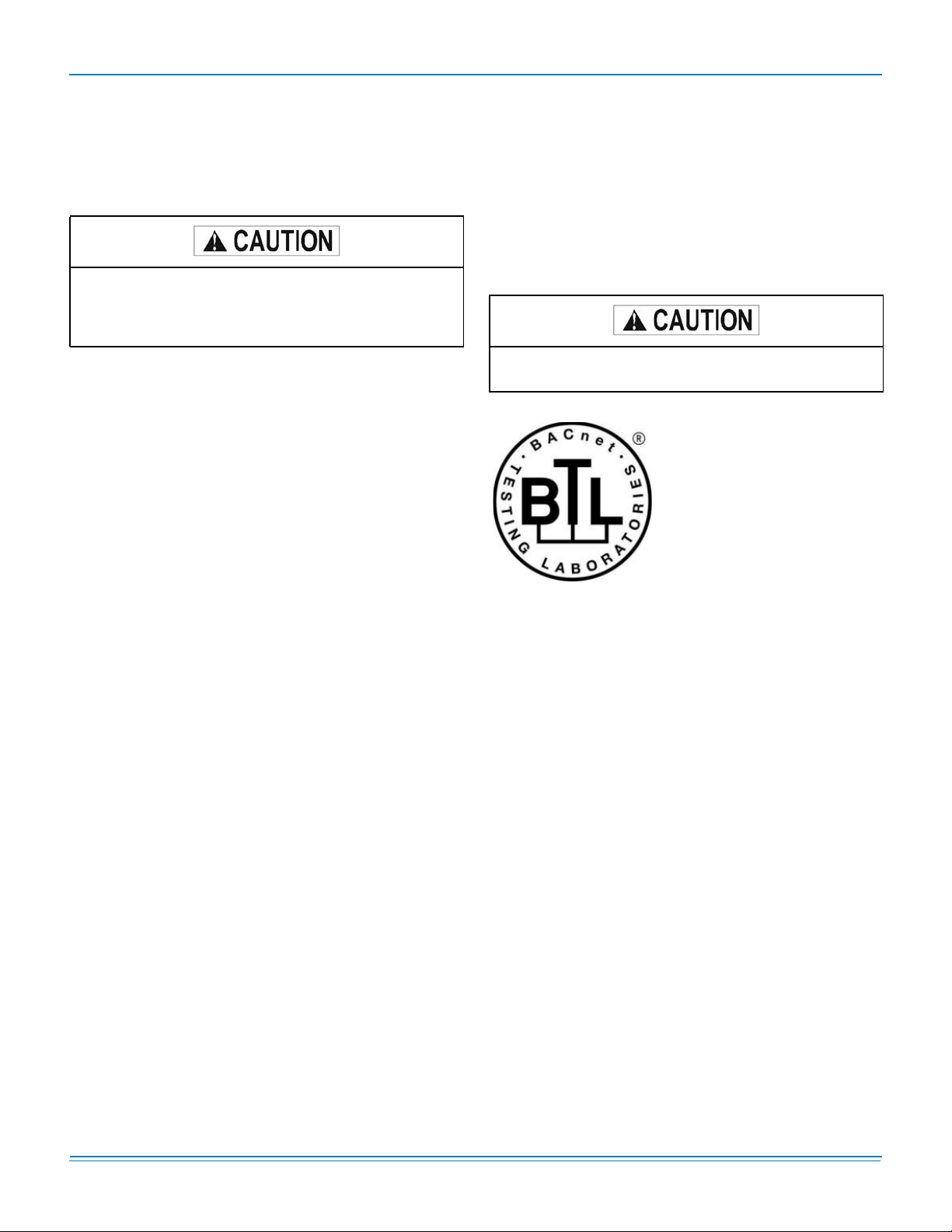
TABLE 4: SIMPLICITY®LINC GATEWAY LED TROUBLESHOOTING
Light Description
PWR This is the power light and should show steady green at all times when the Simplicity Linc is powered.
1031990-UAD-A-0313
SYS ERROR
COMM
ERROR
Config
ERROR
Node Offline
Unused 15 seconds after powering up the 4 unused LEDs will turn on solid for 5 seconds, then turn off.
RX On normal operation of Simplicity Linc, the RX LED will flash when a message is received on the field port.
TX On normal operation of Simplicity Linc, the TX LED will flash when a message is sent on the field port.
RUN
Power Source 24 ± 15% VAC (Obtained from the Roof Top Unit)
Frequency 45 to 65 HZ
Power Consumption Nominal >2 VA
Operating Environment -40 to 160° F (-40 to 70° C) 10 to 95% non-condensing
Size (H x W x D) 5.0 x 2.4 x 1.8 in. (128 x 61 x 45.75 cm)
Weight 0.2 lb. (0.09 kg)
The SYS ERR LED will go on solid 15 seconds after power up. It will turn off after 5 seconds. A steady red light will
indicate there is a system error on the Simplicity Linc. If this occurs, contact UP Tech Services at 1-877-874-7378
COMM ERR LED will go on solid 15 seconds after power up. It will turn off after 5 seconds. A steady red light will
indicate the communications problem if there is a configured node connected to the Simplicity Linc that is offline.
Config ERR LED will go on solid 15 seconds after power up. It will turn off after 5 seconds. A steady amber light will
indicate a configuration error exists in the active configuration. If this occurs, contact UP Tech Services at 1-877874-7378
Node Offline LED will go on solid 15 seconds after power up. It will turn off after 5 seconds. If the Node Offline LED
stays on solid, a node offline condition has occurred.
RUN LED will flash 20 seconds after power up, signifying normal operation. During the first 20 seconds, the LED
should be off.
General
Processor
Type Microchip
SDRAM Memory 2048 bytes
FLASH Memory 1024 bytes w/1,000,000 write cycle capability
Interface
Port 1 Type BACnet MS/TP
Port 1 Speeds 9.6, 19.2, 38.4, 76.8 kbaud
Port 1 Connector 3-pin screw terminals
Port 2 Type Modbus RTU (RS485)
Port 2 Speeds 9.6, 19,2 kbaud
Port 2 Connector 6-pin screw terminals
LAN Cable Screened Twisted-Pair (Belden 9272 or 89272)
LEDs Controller Status; BACnet; Modbus
Switch Selections MAC Address (1-99), Baud Rate
Johnson Controls Unitary Products 21
Page 22

Unused
R2 RS485 TXR2 RS485 RX
Node Oŋine
ConĮg Error
PWR (BACnet)
PWR (RS485)
FIGURE 3: SIMPLICITY
EOL Switch SoŌ Reset
®
LINC BOARD AND LED LAYOUT
Comm Error
Sys Error
Run
R1 RS485 RX
R1 RS485 TX
Subject to change without notice. Printed in U.S.A. 1031990-UAD-A-0313
Copyright © 2013 by Johnson Controls, Inc. All rights reserved. Supersedes: Nothing
Johnson Controls Unitary Products
5005 York Drive
Norman, OK 73069
 Loading...