

Page 1

Smart Equipment Controls
Installation, Operation and Maintenance Manual
Form No. SECIOM.A
Effective Date: 07/05/19
Page 1
Smart Equipment Controls
Installation, Operation, and Maintenance
Manual
Johnson Contr ols
SE-ZEC500-1 and SE-ZEC510-1 Controllers
Page 2

Smart Equipment Controls
Installation, Operation and Maintenance Manual
Form No. SECIOM.A
Effective Date: 07/05/19
Page 2
Table of Contents
Initial Setup .............................................................................................................................................................................. 3
Mounting .............................................................................................................................................................................. 3
Networking .......................................................................................................................................................................... 4
Field Controller (FC) Bus ................................................................................................................................................ 4
SE-ZEC Controller Address ............................................................................................................................................ 4
End-of-line (EOL) Switch ................................................................................................................................................. 5
Optional Components ......................................................................................................................................................... 5
Sensor Actuator (SA) Bus ............................................................................................................................................... 5
Supply Air Temp. Sensor ................................................................................................................................................ 5
Discharge Air Temp. Sensor ........................................................................................................................................... 6
Occupancy Sensor .......................................................................................................................................................... 6
Control Sequences .................................................................................................................................................................. 7
Controller Parameters ............................................................................................................................................................. 7
Parameter Descriptions ....................................................................................................................................................... 7
Static Parameters (All Applications) ................................................................................................................................ 7
Application Specific Parameters ................................................................................................................................... 11
Factory Programmed Parameters ..................................................................................................................................... 12
Default Parameters ....................................................................................................................................................... 12
Size Dependent Parameters ......................................................................................................................................... 13
Sequence Dependent Parameters ................................................................................................................................ 14
Commissioning ...................................................................................................................................................................... 16
Mobile Access Portal (MAP) Gateway .............................................................................................................................. 16
VAV Handheld Balancing Tool .......................................................................................................................................... 17
Troubleshooting .................................................................................................................................................................... 17
er Status LED ............................................................................................................................................................. 18
Pow
Communication Bus Problems .......................................................................................................................................... 18
I/O Wiring ...................................................................................................................................................................... 18
Duplicate Addresses ..................................................................................................................................................... 18
Correcting Physical Communication Bus Problems ...................................................................................................... 18
Parts and Accessories .......................................................................................................................................................... 18
Additional Information ........................................................................................................................................................... 19
Page 3
Smart Equipment Controls
Installation, Operation and Maintenance Manual
Form No. SECIOM.A
Effective Date: 07/05/19
Page 3
Initial Setup
Mounting
To mount the SE-ZEC Controllers:
1. Ensure that you have the appropriate personal protective equipment (PPE), such as a hard hat, safety glasses,
steel toe boots, and gloves.
2. Disconnect power to the VAV unit.
3. Set the MS/TP address, and ensure the end of line (EOL) switch is set to off. Instructions on setting the VAV
address and EOL are in the sections below.
4. Place the SE-ZEC Controller in the proper mounting position on the actuator shaft so that the wiring connections
are easily accessible. Make sure the SE-ZEC Controller base is parallel to the VAV box (perpendicular to the
damper shaft). If needed, use a spacer to offset tipping of the SE-ZEC Controller caused by the shaft bushings.
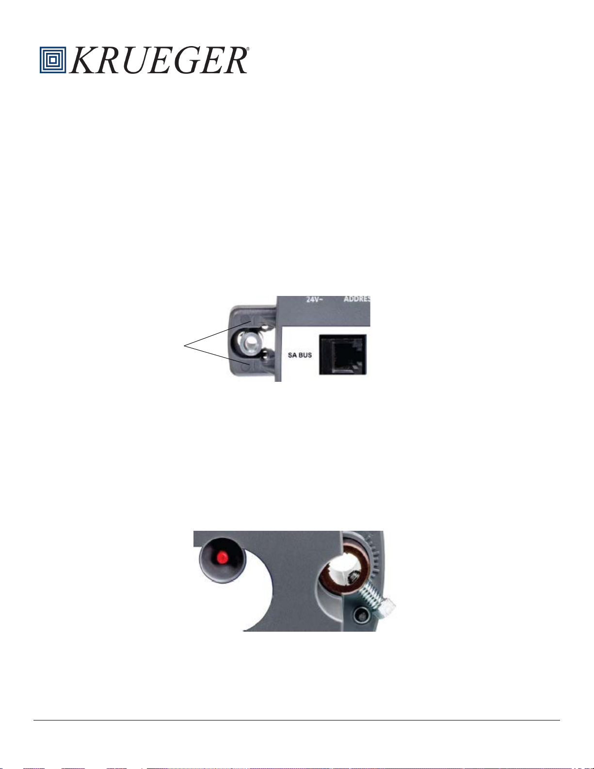
5. Use the alignment marks to center the captive spacer to ensure sufficient movement in either direction.
Fig
. 1: Captive Spacer Alignment Marks
Alignment
guide
6. Sec
7. Locate the damper position using the typical marking on the end of the damper shaft.
8. Note the direction, clockwise (CW) or counterclockwise (CCW), required to close the damper. The actuator setup
9. Push down and hold the manual override button and turn the SE-ZEC Controller until it contacts the mechanical
10. Ti
11. Put a loop in the pneumatic tubing, to trap condensation, when you attach the tubing to the SE-ZEC Controller
ure the self-drilling #10 screw through the captive spacer with a power screwdriver and 4” (100 mm) extension
socket. Otherwise, use a punch to mark the position of the shoulder washer, and then drill a hole into the VAV box
using a 5/16” drill bit. Insert the mounting screw and tighten against the spacer.
depends on the necessary amount of rotation required for the damper to go from full-open to full-closed. For 90°
rotation, install the damper full-closed.
end-stop at either the full-closed or full-open position.
. 2: Manual Override and Coupler
Fig
ghten the square coupler bolt to the shaft using a 5/16” (8 mm) wrench or a 3/8” (10 mm) 12-point socket.
Tighten to 95 to 105 lb·in (10.5 to 11.5 N·m)
pressure transducer ports. Loop the tubing before you make the final connections.
Page 4
Smart Equipment Controls
Installation, Operation and Maintenance Manual
Form No. SECIOM.A
Effective Date: 07/05/19
Page 4
12. Push the manual override button, and turn the actuator coupling manually to ensure the actuator can rotate from
full-closed to full-open positions without bindi ng.
13. Complete the mounting by rotating the damper to the full-open position.
Networking
Field Controller (FC) Bus
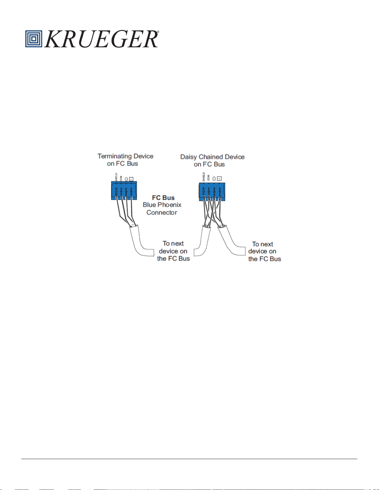
The field controller (FC) Bus terminal block is a blue, removable, 4-terminal plug that is keyed to only fit in to the boardmounted, gray FC Bus jack. Wire the removable FC Bus terminal block plugs on the SE-ZEC Controller and other FC Bus
controllers in a daisy-chain configuration usin g 3-wire twisted, shielded cable.
Fig. 3: FC Bus Connections
SE-ZEC Controller Address
SE-ZEC Controllers are master devices on BACnet MS/TP (SA or FC) Buses. Before operating field controllers on a Bus,
you must set a valid and unique device address for each controller on the Bus. You set a field controller’s device address
by setting the positions of the switches on the devise address DIP switch block at the top of the controller. Device
addresses 4-127 are the valid addresses for the SE-ZEC controller. SE-ZEC Controllers ship with all address switches set
to ON. Set a valid and unique device address on the field controller before applying power to the controller on the Bus.
The DIP switch block has eight switches numbered 128, 64, 32, 16, 8, 4, 2, and 1.
To set the device addresses on a ZEC field controller:
1. Set all of the switches on the field controller’s device address DIP switch block (128 through 1) to OFF.
2. Set one or more of the seven address switches from 64 to 1 to ON, so that the sum of the switch numbers set to ON
equals the intended device address. Set the highest number switch that is less than or equal to the intended device
address to ON. Then continue setting lower numbered switches until the total equals the intended address.
For example: If the intended device address is 21, set the switches so that 16 + 4 + 1 = 21.
a. Set switch 16 to ON
b. Set switch 4 to ON
c. Set switch 1 to ON
3. Set a unique and sequential device address for each of the field controllers connected on the FC Bus, starting with
device address 4. To ensure the best Bus performance, set sequential device address es with no gaps in the de vice
Page 5
Smart Equipment Controls
Installation, Operation and Maintenance Manual
Form No. SECIOM.A
Effective Date: 07/05/19
Page 5
address range (4, 5, 6, and so on). The field controllers do not need to be physically connected on the Bus in their
numerical device address order.
4. Write each field controller’s device address on the white label below the DIP switch block on the controller’s cover.
End-of-line (EOL) Switch
The EOL switch must be set to ON for the two devices located at either end of each bus segment on an FC bus. The EOL
switches must be set to OFF for all other devices on the bus segment on an FC bus.
Optional Components
Sensor Actuator (SA) Bus
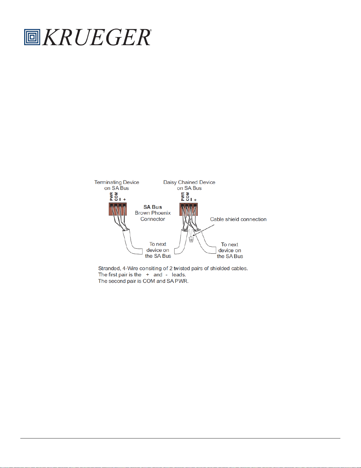
Factory or field supplied zone sensors are wired to the SA bus on the SE-ZEC Controller. The SA Bus is a brown,
removable 4-terminal plug that is keyed to only fit into the board mounted SA bus. Wire the removable SA bus terminal
block plugs on the SE-ZEC Controller and other field devices in a daisy-chain configuration using 4-wire, shielded cable.
Fig. 4: SA Bus Connections
Supply Air Temp. Sensor
Factory or field-supplied supply air temperature sensors can be used to measure the supply air temperature at the inlet of
the VAV box. The supply air temperature is wired between terminals ICOM3 and IN3 on the SE-ZEC Controller. The
sensor should be mounted in the inlet duct centered in the side of the ductwork. Avoid installing the sensor near an elbow,
take off or transition. Avoid blocking air to the primary airflow sensor.
Factory provided nickel (1k ohm) temperature sensors have 4” long probes and stainless steel mounting flanges with (2)
provided hex-head self-drilling mounting screws. Sensors come equipped with 10 ft. plenum rated cables with ¼” internal
thread insulated quick-connect terminations on leads. Install sensor by drilling a hole into the ductwork, inserting the
sensor, and securing with provided screws. The sensor tip should not touch any part of the ductwork.
With the supply air temperature sensor installed, the SE-ZEC controller will change its control sequence based on the
measured supply air temperature. When parameter Heating Limit Enable is TRUE the controller will not allow re-heat to
engage when the supply air temperature is greater than the value set in Heating Supply Air Limit.
Additionally, the controller will switch to warmup mode when warmup conditions are present. Warmup conditions are
present when the supply air temperature (SAT) sensor value exceeds the zone temperature (ZNT) sensor in unoccupied
mode or exceeds it by the Warmup Differential in occupied mode. While in Warmup mode the minimum flow will be set to
the Warmup Min Flow.
Page 6

Smart Equipment Controls
Installation, Operation and Maintenance Manual
Form No. SECIOM.A
Effective Date: 07/05/19
Page 6
SE-ZEC Occupancy Determination
Controller Type
ZEC500 (Standalone)
ZEC510 (Networked)
The controller will switch from
Setpoint the state is set to Occupied
The controller will read the occupancy
between Occupied and Unoccupied
The building automation system
and Unoccupied states. A room
Discharge Air Temp. Sensor
Factory or field supplied discharge air temperature sensors can be used to measure the temperature of the air being
discharged from the VAV box. The discharge air temperature sensor is wired between terminals ICOM1 and IN1 on the
SE-ZEC controller. The sensor should be mounted a minimum of 36” from the discharge of the unit and be centered in the
side of the ductwork. Avoid installing the sensor near an elbow, take off, or transition.
Factory provided nickel (1k ohm) temperature sensors have 4” long probes and stainless steel mounting flanges with (2)
provided hex-head self-drilling mounting screws. Sensors come equipped with 10 ft. plenum rated cables with ¼” internal
thread insulated quick-connect terminations on leads. Install sensor by drilling a hole into the ductwork, inserting the
sensor, and securing with provided screws. The sensor tip should not touch any part of the ductwork.
Occupancy Sensor
The SE-ZEC Controllers adjust the heating and cooling temperature setpoints, as well as the airflow setpoints based on
the zone occupancy. There are three different states of zone occupancy:
• Occupied Mode
o Uses Occupied Heating (68°F) and Occupied Cooling (72°F) temperature setpoints as well as Occupi
eating and Occupied Cooling Airflow setpoints
H
o For Series Fan Powered Terminals the Fan is always on
o For Parallel Fan Powered Terminals the Fan is only on during a call for heating
• Standby Mode
o Uses Standby Heating (66°F) and Standby Cooling (77°F) temperature setpoints as well as Unoccupi
H
eating and Unoccupied Cooling Airflow setpoints
o For Series Fan Powered Terminals the Fan is always on
o For Parallel Fan Powered Terminals the Fan is only on during a call for heating
• Unoccupied Mode
o Uses Unoccupied Heating (55°F) and Unoccupied Cooling (85°F) temperature setpoints as well as
Unoccupied Heating and Unoccupied Cooling Airflow setpoints
o For Series Fan Powered Terminals the Fan is only on during a call for heating or cooling
o For Parallel Fan Powered Terminals the Fan is only on during a call for heating
ed
ed
Table 1 below shows how occupancy states are determined for the SE-ZEC Controllers.
Terminal Unit Type
Single Duct Terminal Unit
Fan Powered Terminal Unit
Table 1: SE-ZEC Occupancy Determination
Occupied to Unoccupied states by
comparing the measured airflow to
the Occupancy Determination Flow
Setpoint. When the measured airflow
is below the Occupancy
Determination Flow Setpoint the state
is set to Unoccupied. When the
measured airflow is above the
Occupancy Determination Flow
sensor wired between IN2 and
ICOM2 on the controller to switch
The building automation system
(BAS) will schedule when t he
controller will switch from Occupied
and Unoccupied states. A room
occupancy sensor (wired to IN2 and
ICOM2 on the controller) can be used
to temporarily set the VAV box to
Standby mode when occupancy is not
sensed.
(BAS) will schedule when the
controller will switch from Occupied
Page 7

Smart Equipment Controls
Installation, Operation and Maintenance Manual
Form No. SECIOM.A
Effective Date: 07/05/19
Page 7
states. The occupancy sensor can be
always be in Occupied mode.
occupancy sensor (wired to IN2 and
Smart Equipment Controls - Control Sequences
Single Duct
Series Fan Powered
Parallel Fan Powered
ZEC500
ZEC510
ZEC500
ZEC510
ZEC500
ZEC510
Cooling Only
6101
7101
6201
7201
6301
7301
1-Stage Electric Heat
6102
7102
6202
7202
6302
7302
2-Stage Electric Heat
6103
7103
6203
7203
6303
7303
3-Stage Electric Heat
6104
7104
6204
7204
6304
7304
Proportional Electric Heat
6105
7105
6205
7205
6305
7305
On/Off Hot Water Heat
6106
7106
6206
7206
6306
7306
Floating Hot Water Heat
6107
7107
6207
7207
6307
7307
Proportional Hot Water Heat
6108
7108
6208
7208
6308
7308
Supplemental Heat
6109
7109
6209
7209
6309
7309
Menu 1
Menu 2
Parameter Name
Parameter Description
Parameter Values
Displays the active baud rate used for network
communication.
a room occupancy sensor or another
kind of occupancy detection (such as
a duct pressure switch*). Without an
occupancy sensor, the controller will
n optional factory provided occupancy pressure switch is available for standalone fan powered terminal units t
*A
det
ermine occupancy by measuring duct pressure to determine whether the air handler is on (zone is occupied) or off
(zone is unoccupied).
ICOM2 on the controller) can be used
to temporarily set the VAV box to
Standby mode when occupancy is not
sensed.
o
Control Sequences
VAV boxes with Smart Equipment Controls will be factory mounted and wired according to the selected control sequence.
Links to each individual control submittal are shown below:
Table 2: Control Sequences
Description
Controller Parameters
Parameter Descriptions
This section provides information on the SE-ZEC Controller Parameters.
Static Parameters (All Applications)
The list of available SE-ZEC Controller Parameters changes depending on the application type that is selected
(Staged/Incremental/SCR). Table 2 shows the SE-ZEC Controller parameters that are available for every application
(Staged/Incremental/SCR).
Table 3: Default SE-ZEC Controller Parameters
Home Page Setup Active Baud Rate
Read Only
Page 8

Smart Equipment Controls
Installation, Operation and Maintenance Manual
Form No. SECIOM.A
Effective Date: 07/05/19
Page 8
Menu 1
Menu 2
Parameter Name
Parameter Description
Parameter Values
Adjustable:
Proportional SCR
Allows PRAC+ auto tuning algorithm to
Setting this to Disable turns off this feature.
This feature drives the VAV box damper shut and
so it reads zero.
Sets the BACnet ID for the BACnet MS/TP
system.
Read Only:
0-4194302
Box Heating
Installed
Adjustable:
False/True
Read Only: No
Stage Electric
Discharge Air
Offset
Adjustable:
None/Parallel/Series
Enables/Disables the activation of re-hea t when
temperature is too high.
Determines whether box or supplemental heat is
turned on first.
Adjustable:
Supplemental/Box
Sets the highest inlet air temperature at which re-
cannot engage.
Sets airflow threshold for determining occupancy
the unoccupied mode.
Occupancy
Polarity
Sets input polarity of occupancy sensor when
Occupancy Sensor Enable is T rue. Open =
Adjustable:
Close/Open
Home Page Setup
Home Page Setup Application Type Set the type of application for the VAV Box.
Home Page Setup
Home Page Setup
Home Page Setup BACnet Id
Home Page Setup
Home Page Setup Box Heating Type Displays the type of heat installed.
Home Page Setup Damper Mode
Home Page Setup
Actuator Stroke
Time
Auto Tune
Enable
Autocalibration
Command
Temperature
Sets the damper actuator stroke time. Note: The
SE-ZEC5X0-1 actuator is a 60 second motor.
continuously tune the loops in the controller.
once shut offsets the differential pressure sensor
Specifies if box re-heat is installed (local re-heat).
Defines the direction of the damper rotation.
(Normal = CCW to close, Reverse = CW to close)
Used to calibrate the supply air temperature
sensor.
Adjustable:
30-120 seconds
Incremental/Staged/
Adjustable:
Enable/Disable
Adjustable:
False/True
Heat/1 Stage
Electric /2 Stage
Electric/Modulating
Hot Water Valve/3
Adjustable:
Normal/Reverse
Adjustable:
-5°F to 5°F
Home Page Setup Fan Control Type Set the type of fan for the VAV Box.
Home Page Setup
Home Page Setup Heating Priority
Home Page Setup
Home Page Setup
Home Page Setup
Heating Limit
Enable
Heating Supply
Air Limit
Occupancy
Determination
Flow Setpoint
the incoming air temperature exceeds the
temperature set in Heating Supply Air Limit. This
is to avoid engaging re-heat when the inlet
heat can be engaged when Heating Limit Enable
is set to True. When the inlet air temperature is
higher than Heating Supply Air Limit, re-heat
when Occupancy Sensor Enable is false.
Whenever the measured flow exceeds the
Occupancy Determination Flow Setpoint, the
system will be in the occupied mode. Whenever
the measured flow is less than the Occupancy
Determination Flow Setpoint, the system will be in
Adjustable:
False/True
Adjustable
Adjustable:
0 cfm to 10000 cfm
Page 9

Smart Equipment Controls
Form No. SECIOM.A
Effective Date: 07/05/19
Page 9
Menu 1
Menu 2
Parameter Name
Parameter Description
Parameter Values
Unoccupied when open, Closed = Unoc c upie d
when closed.
Home Page Setup
Enables determining occupancy by reading IN2
Flow Setpoint.
Resets the PRAC+ tuning parameters of the PID
controllers to the factory defaults.
Adjustable:
Enable/Disable
Sets the amount of time the controller waits to
when power is restored.
After switching to occupied mode, the box will stay
mode.
Enables Standalone Mode. This mode is intended
Enable is True.
Supplemental
Heating Installed
Specifies if re-heat is installed in the zone/space
(non box re-heat).
Adjustable:
False/True
Supply Air
Offset
Supply Airflow
Pickup Gain
Amplification provided by the pitot tube for supply
flow.
Shows the supply inlet area used to calculate the
supply flow.
Adjustable:
0 sq. ft. to 8.0 sq. ft.
The flow setpoint the damper is controlling the
morning warmup conditions, etc.)
Warmer/Cooler
Adjust Enable
Enables the warmer/cooler adjustment to offset
the current setpoint.
Adjustable:
False/True
Zone
Offset
Effective Cooling
Setpoint
Home Page Setup PID Tuning Reset
Home Page Setup
Occupancy
Sensor Enable
Power Fail
Restart Time
Installation, Operation and Maintenance Manual
and ICOM2 on the controller via an occupancy
sensor. When Occupancy Sensor Enable is
disabled, occupancy is determined by comparing
measured airflow to the Occupancy Determination
operate the unit after power is restored when
Power Fail Restart Enable is True. This is to avoid
a power surge with lights, computers, and other
electrical loads that come back on immediately
Adjustable:
Enable/Disable
Adjustable
Home Page Setup
Home Page Setup Standalone Mode
Home Page Setup
Home Page Setup
Home Page Setup
Home Page Setup Supply Area
Home Page Setup Supply Flow The supply airflow measured by the VAV box. Read Only
Standalone Min
Occupied Time
Temperature
in occupied mode for at least the amount of time
specified in Standalone Min Occupied Time,
before being able to switch back to unoccupied
to allow the controller to utilize unoccupied
setpoints when there is no connection to a
building automation system. When Standalone
Mode is enabled, occupancy is determ ined b y
comparing the measured flow against the
Occupancy Determinati on Flo w Setpoi nt when
Occupancy Sensor Enable if False, or by using
the Occupancy Sensor when Occ upanc y Sens or
Used to calibrate the supply air temperature
sensor.
Adjustable:
0-360 minutes
Adjustable: Off/On
Adjustable:
-5°F to 5°F
Adjustable
Home Page Setup
Home Page Setup
Home Page Setup
Home Page Setpoints
Supply Flow
Setpoint
Temperature
supply air flow to. This will be based on the unit
conditions (occupancy, temperature setpoint,
Used to calibrate the zone temperature sensor.
Effective Cooling Setpoint Read Only
Read Only
Adjustable:
-5°F to 5°F
Page 10

Smart Equipment Controls
Installation, Operation and Maintenance Manual
Form No. SECIOM.A
Effective Date: 07/05/19
Page 10
Menu 1
Menu 2
Parameter Name
Parameter Description
Parameter Values
Effective Heating
Setpoint
When occupied the thermostat controls cooling to
Defaults to 72°F.
When occupied the thermostat controls heating to
Defaults to 68°F.
In order for the Standby Cooling Setpoint to
unit is occupied. Defaults to 74°F.
In order for the Standby Heating Setpoint to
unit is occupied. Defaults to 66°F.
Unoccupied
Cooling Setpoint
When unoccupied the thermostat controls cooling
to this level. Defaults to 80°F.
Adjustable:
46°F to 99°F
When unoccupied the thermostat controls heating
Setpoint. Defaults to 60°F.
This is the range that the warmer cooler
adjustment at the sensor. Defaults to 5°F.
Sets the required differential between the supply
Flow.
Sets the maximum supply air flow of the VAV box
when cooling.
Adjustable:
0 cfm to 10000 cfm
Occupied Cooling
Min Flow
Sets the minimum supply air flow of the VAV box
when cooling.
Adjustable:
0 cfm to 10000 cfm
Sets the minimum supply air flow of the VAV box
heat to energize.
Sets the minimum heating flow for electric reheat
per kW of electric heat.
Sets the minimum supply air flow of the VAV box
mode.
Home Page Setpoints
Home Page Setpoints
Home Page Setpoints
Home Page Setpoints
Home Page Setpoints
Home Page Setpoints
Home Page Setpoints
Home Page Setpoints
Occupied Cooling
Setpoint
Occupied Heating
Setpoint
Standby Cooling
Setpoint
Standby Heating
Setpoint
Unoccupied
Heating Setpoint
Warmer/Cooler
Adjust Range
Effective Heating Setpoint Read Only
this level. Set above Occupied Heating Setpoint.
this level. Set below Occupied Cooling Setpoint.
appear, set the Occupancy Schedule to external.
When set to external the zone switches to this
setpoint when motion is no longer sensed and the
appear, set the Occupancy Schedule to external.
When set to external, the zone switches to this
setpoint when motion is no longer sensed and the
to this level. Set below Unoccupied Cooli ng
adjustment on the sensor can affect the setpoint.
Setting it to zero (0) means the user has no
Adjustable:
46°F to 99°F
Adjustable:
45°F to 98°F
Adjustable:
46°F to 99°F
Adjustable:
45°F to 98°F
Adjustable:
45°F to 98°F
Adjustable:
0°F to 5°F
Home Page Setpoints
Home Page Commissioning Cooling Max Flow
Home Page Commissioning
Home Page Commissioning
Home Page Commissioning
Home Page Commissioning
Warmup
Differential
Occupied Heating
Min Flow
Staged Device
Min Flow
Unoccupied
Cooling Min Flow
air temperature (SAT) sensor and the zone
temperature (ZNT) sensor in occupied mode to
notify the controller that warmup conditions are
present. When warmup conditions are present the
minimum supply airflow will be set to Warmup Min
when heating. Note: When the zone is in heating
mode, the supply air flow is constant. Thus, no
maximum heating air flow. This value must
exceed Staged Device Min Flow to allow electric
control. This parameter serves an additional
control safety to the high-limit switches in the box.
It is best practice to set this parameter to 70 cfm
when unoccupied cooling and in the cooling
Adjustable:
0 cfm to 10000 cfm
Adjustable:
0 cfm to 10000 cfm
Adjustable:
0 cfm to 10000 cfm
Page 11

Smart Equipment Controls
Installation, Operation and Maintenance Manual
Form No. SECIOM.A
Effective Date: 07/05/19
Page 11
Menu 1
Menu 2
Parameter Name
Parameter Description
Parameter Values
Sets the minimum supply air flow of the VAV box
mode.
Sets the minimum supply airflow when warmup
by the Warmup Differential in occupied mode.
Discharge Air
Velocity Pressure
Displays differential pressure measured across
the airflow probe.
Occupancy
Status
Supply Air
Temperature
Supply air temperature reading from the supply air
temperature sensor (if included).
Zone
Temperature
Supply Air
Damper Output
Displays damper position (0% = Fully Clos ed,
100% = Fully Open).
Supply Fan
Command
Factory Use
Only
STG
INC
SCR
Reverses the direction of the incremental heating
wiring to the actuator.
Home
Page
Box Heating
Stroke Time
Sets the actuator stroke time for incremental
heating valve.
Adjustable:
30-120 seconds
Home
Page
Dual Max
Enable
Adjustable:
Enable/Disable
Home
Page
Number Of
Heating Stages
Reverses the direction of the incremental
this or reverse the wiring to the actuator.
Supplemental
Time
Home Page Commissioning
Home Page Commissioning
Inputs
Inputs
Inputs
Inputs
Inputs
Outputs
Outputs
Parameters
Unoccupied
Heating Min Flow
Warmup Min
Flow
D
ischarge Air
Temperature
when unoccupied heating and in the heating
conditions are present. Warmup conditions are
present when the supply air temperature (SAT)
sensor value exceeds the zone temperature
(ZNT) sensor in unoccupied mode or exceeds it
Discharge air temperature reading from the
discharge air temperature sensor (if included).
Displays state of occupancy input. Read Only
Displays temperature measured at zone sensor. Ready Only
Displays fan status. Read Only
Adjustable:
0 cfm to 10000 cfm
Adjustable:
0 cfm to 10000 cfm
Read Only
Read Only
Read Only
Read Only
Application Specific Parameters
Table 3 below shows application specific parameters for the staged, incremental, and SCR applications:
Table 4: Application Specific SE-ZEC Controller Parameters
Menu 1 Menu 2
Home
Page
Home
Page
Home
Page
Setup
Setup
Setup
Setup
Setup
Setup
Parameter
Name
Box Heating
Polarity
Supplemental
Heating Polarity
Heating Stroke
●
●
●
●
● ●
● ●
Parameter Description Parameter Values
valve. You can either switch this or reverse the
Enables the Dual Max Control Sequence
S
ets the number of box heating stages. Adjustable: 0 - 3
supplemental heating valve. You can either switch
ets the actuator stroke time for incremental
S
supplemental heating valve.
Adjustable:
Normal/Reverse
Adjustable:
Normal/Reverse
Adjustable:
30-120 seconds
Page 12

Smart Equipment Controls
Form No. SECIOM.A
Effective Date: 07/05/19
Page 12
Home
When the space temperature drops below the
maximum f low.
When the space temperature drops below the
maximum f low.
Heating
Command
Displays the heat command (on/off) of the heat
output to the proportional actuator or electric heat
Displays the heat command (0-100%) of the heat
output to the proportional actuator or electric heat
Heating Stage 1
Command
Heating Stage 2
Command
Heating Stage 3
Command
Displays the supplemental heat command (0actuator or electric heat
Supplemental
Command
Parameter Name
Value
Supplemental Heating Stroke Time
N/A
Supplemental Heating Polarity
N/A
BACnet ID
10000
BACnet Encoding Type
ISO10646
Power Fail Restart Time
180
Warmer/Cooler Adjust Range
3
Warmup Differential
10
Autocalibration Command
FALSE
Zone Temperature Offset
0
Page
Home
Page
Setpoints
Setpoints
Discharge Air
Setpoint
Heating Max
Discharge Air
Temperature
Setpoint
●
●
Installation, Operation and Maintenance Manual
heating setpoint the zone controller will start from
the supply air temperature setpoint and reset to the
supply air setpoint heating max. Once the heating
max setpoint is reached the supply air flow will be
reset from heating minimum flow to cooling
heating setpoint the zone controller will start from
the supply air temperature setpoint and reset to the
supply air setpoint heating max. Once the heating
max setpoint is reached the supply air flow will be
reset from heating minimum flow to cooling
Adjustable:
45°F to 140°F
Adjustable:
45°F to 130°F
Outputs
Outputs Heating Output
Outputs
Outputs
Outputs
S
Outputs
Outputs
upplemental
Heating Output
Heating Stage 1
●
●
●
●
●
● ●
● ●
Read Only
Read Only
D
isplays status of stage 1 heat. Read Only
D
isplays status of stage 2 heat. Read Only
D
isplays status of stage 3 heat. Read Only
100%) of the heat output to the proportional
D
isplays status of stage 1 supplemental heat. Read Only
Read Only
Factory Programmed Parameters
This section outlines how the SE-ZEC Controller parameters are programmed at the factory.
Default Parameters
The following table shows factory programming for SE-ZEC Controller parameters that are independent of inlet size and
control sequence.
Table 5: Factory Programmed Default Parameters
Page 13

Smart Equipment Controls
Installation, Operation and Maintenance Manual
Form No. SECIOM.A
Effective Date: 07/05/19
Page 13
Supply Air Temperature Offset
0
Discharge Air Temperature Offset
0
Heating Limit Enable
TRUE
Heating Supply Air Limit
75
Rotation
90
Warmup Min Flow
200
Occupied Cooling Setpoint
72
Occupied Heating Setpoint
68
Unoccupied Cooling Setpoint
85
Unoccupied Heating Setpoint
55
Standby Cooling Setpoint
77
Standby Heating Setpoint
66
Standalone Min Occupied Time
15
Actuator Stroke Time
60
Size
4 5 6 7 8 9 10
12
14
16
20
22
Size Dependent Parameters
The following table shows factory programming for SE-ZEC Controller parameters that are inlet size dependent.
Table 6: Factory Programmed Size Dependent Parameters
Supply Area 0.087 0.136 0.196 0.267 0.349 0.442 0.545 0.785 1.069 1.396 0.738 2.667
Supply
Airflow
Pickup Gain
Cooling
Maximum
Flow
Occupied
Cooling Min
Flow
Unoccupied
Cooling Min
Flow
Occupied
Heating Min
Flow
Unoccupied
Heating Min
Flow
Staged
Device Min
Flow
2.329 2.327 2.332 2.325 2.329 2.327 2.327 2.327 2.328 2.328 1.982 2.328
Per
Order
Per
Order
Per
Order
Per
Order
Per
Order
55 85 110 140 190 240 300 425 580 750 425 1800
Per
Order
Per
Order
Per
Order
Per
Order
Per
Order
Per
Order
Per
Order
Per
Order
Per
Order
Per
Order
Per
Order
Per
Order
Per
Order
Per
Order
Per
Order
Per
Order
Per
Order
Per
Order
Per
Order
Per
Order
Per
Order
Per
Order
Per
Order
Per
Order
Per
Order
Per
Order
Per
Order
Per
Order
Per
Order
Per
Order
Per
Order
Per
Order
Per
Order
Per
Order
Per
Order
Per
Order
Per
Order
Per
Order
Per
Order
Per
Order
Per
Order
Per
Order
Per
Order
Per
Order
Per
Order
Per
Order
Per
Order
Per
Order
Per
Order
Per
Order
Per
Order
Per
Order
Per
Order
Per
Order
Per
Order
Page 14

Smart Equipment Controls
Installation, Operation and Maintenance Manual
Form No. SECIOM.A
Effective Date: 07/05/19
Page 14
6102, 7102,
6106, 7106
6105, 7105,
6108, 7108
6202, 7202,
6206, 7206
6205, 7205,
6208, 7208
Occupancy
Determination
29 46 66 89 117 148 182 262 357 466 267 891
Flow Setpoint
Sequence Dependent Par am eter s
The following section shows factory programming for SE-ZEC Controller parameters that are control sequence specific.
Table 7: Factory Programmed Sequence Specific Parameters
Control Code 6101, 7101
Heating Type Cooling Only Staged Staged Staged SCR Incremental Staged
FAN-TYPE None None None None None None None
Number of Heating
Stages
Damper Polarity Normal Normal Normal Normal Normal Normal Normal
Supplemental
Heating Installed
Box Heating Installed FALSE TRUE TRUE TRUE TRUE TRUE FALSE
Box Heating Stroke
Time
Box Heating Polarity N/A N/A N/A N/A N/A Normal N/A
Staged Device Min
Flow
No Heat 1 2 3 No Stages No Stages No Heat
FALSE FALSE FALSE FALSE FALSE FALSE TRUE
N/A N/A N/A N/A N/A 60 N/A
Per Size
Table
Per Size
Table
6103, 7103 6104, 7104
Per Size
Table
Per Size
Table
Per Size
Table
6107, 7107 6109, 7109
N/A
Per Size
Table
Occupancy
Determination Flow
Setpoint
Occupancy Polarity N/A N/A N/A N/A N/A N/A N/A
Occupancy Sensor
Enable
Standalone Mode TRUE,FALSE
Control Code 6201, 7201
Heating Type Cooling Only Staged Staged Staged SCR Incremental Staged
Per Size
Table
FALSE FALSE FALSE FALSE FALSE FALSE FALSE
Per Size
Table
TRUE,FALSE
TRUE,FALSE
Per Size
Table
TRUE,FALSE TRUE,FALSE
Per Size
Table
6203, 7203 6204, 7204
Per Size
Table
TRUE,FALSE
TRUE,FALSE
Per Size
Table
TRUE,FALSE TRUE,FALSE
6207, 7207 6209, 7209
Per Size
Table
Page 15

Smart Equipment Controls
Installation, Operation and Maintenance Manual
Form No. SECIOM.A
Effective Date: 07/05/19
Page 15
6302, 7302,
6306, 7306
6305, 7305,
6308, 7308
FAN-TYPE Series Series Series Series Series Series Series
Number of Heating
Stages
Damper Polarity Reverse Reverse Reverse Reverse Reverse Reverse Reverse
Supplemental
Heating Installed
Box Heating Installed TRUE TRUE TRUE TRUE TRUE TRUE TRUE
Box Heating Stroke
Time
Box Heating Polarity N/A N/A N/A N/A N/A Normal N/A
Staged Device Min
Flow
Occupancy
Determination Flow
Setpoint
Occupancy Polarity Close Close Close Close Close Close Close
No Heat 1 2 3 No Stages No Stages No Heat
FALSE FALSE FALSE FALSE FALSE FALSE TRUE
N/A N/A N/A N/A N/A 60 N/A
0 0 0 0 0 N/A 0
0 0 0 0 0 0 0
Occupancy Sensor
Enable
Standalone Mode TRUE,FALSE
Control Code 6301, 7301
Heating Type Cooling Only Staged Staged Staged SCR Incremental Staged
FAN-TYPE Parallel Parallel Parallel Parallel Parallel Parallel Parallel
Number of Heating
Stages
Damper Polarity Reverse Reverse Reverse Reverse Reverse Reverse Reverse
Supplemental
Heating Installed
Box Heating Installed TRUE TRUE TRUE TRUE TRUE TRUE TRUE
Box Heating Stroke
Time
TRUE TRUE TRUE TRUE TRUE TRUE TRUE
TRUE,FALSE
TRUE,FALSE
TRUE,FALSE TRUE,FALSE
6303, 7303 6304, 7304
No Heat 1 2 3 No Stages No Stages No Heat
FALSE FALSE FALSE FALSE FALSE FALSE TRUE
N/A N/A N/A N/A N/A 60 N/A
TRUE,FALSE
TRUE,FALSE
TRUE,FALSE TRUE,FALSE
6307, 7307 6309, 7309
Page 16

Smart Equipment Controls
Installation, Operation and Maintenance Manual
Form No. SECIOM.A
Effective Date: 07/05/19
Page 16
Box Heating Polarity N/A N/A N/A N/A N/A Normal N/A
Staged Device Min
Flow
Occupancy
Determination Flow
Setpoint
Occupancy Polarity Close Close Close Close Close Close Close
Occupancy Sensor
Enable
Standalone Mode TRUE,FALSE
0 0 0 0 0 N/A 0
0 0 0 0 0 0 0
TRUE TRUE TRUE TRUE TRUE TRUE TRUE
TRUE,FALSE
TRUE,FALSE
TRUE,FALSE TRUE,FALSE
TRUE,FALSE
TRUE,FALSE
TRUE,FALSE TRUE,FALSE
Commissioning
For networked units, SE-ZEC Controller parameters can be changed by the BAS. For stand-alone units, controller
parameters can only be changed using the optional MAP Tool. An optional VAV Handheld balancing tool is available to
aid in the balancing process.
Mobile Access Portal (MAP) Gateway
The Mobile Access Portal (MAP) Gateway is an alternate local display solution or a temporary portable commissioning
device that enables users to leverage the power of mobility using smart phones, tablets, or laptop computers to interact
with building automation equipment controls. The MAP Gateway serves up web pages through a built-in Wi-Fi access
point or tethered Ethernet connection, which allows users to view and edit equipment controller configuration parameters,
setpoints, schedules, and alarms through a browser. A mobile application is not required to use the MAP Gateway with
your mobile device.
The MAP Gateway can be used to see field bus devices on Metasys® systems, Facility Explorer systems, and Smart
Equipment rooftop units (RTUs) with unit control boards (UCBs). The MAP Gateway supports Johnson Controls® branded
Field Controllers, including FEC, FAC, VMA, PCA, PCG, and PCV Series devices. MAP Gateway also supports the
TEC3000 Series Thermostats.
The MAP Gateway comes in two configurations: a portable configuration and a stationary configuration. The portable
configuration is an optional f ac tor y provided acces s ory (Part # PC-01-0206). PC-01-0206 includes the MAP Gateway, RJ12 cable, bumper guard, and lanyard. To use the MAP Gateway:
1. Connect the MAP Gateway to Equipment
a. Use the supplied RJ-12 cable to connect the RS-485 port of the MAP Gateway to the sensor bus or field
bus port of the equipment controller, or to the zone sensor connected to the equipment controller
b. T
he MAP Gateway LEDs flash, indicating that the device is initializing. When the fault LED turns off
.
and
the Wi-Fi LEDs flash in succession, the MAP Gateway is ready to use.
2. Connect to the MAP Gateway Wi-Fi Network
a. In the Wi-Fi settings of your mobile device or laptop, connect to the MAP Gateway Wi-Fi network usi
he credentials found in the MAP Gateway Quick Start Guide that is provided with the MAP Gateway (Part
t
ng
No. 24-10737-16)
3. Open a Web Browser
a. On your mobile device or laptop navigate to www.mapgwy.com on your internet browser.
Page 17

Smart Equipment Controls
Installation, Operation and Maintenance Manual
Form No. SECIOM.A
Effective Date: 07/05/19
Page 17
4. Log in to the MAP Gateway
a. Log in to the MAP Gateway using the default Admin login credentials found in the MAP Gateway Quick
Start Guide that is provided with the MAP Gateway (Part No. 24-10737-16)
5. Change Passwords
a. The first time you log in to the MAP Gateway, the Change Password and Passphrase web page appears.
You must change the Admin password and Wi-Fi passphrase.
SSID, the web server restarts and you must rejoin the MAP Gateway Wi-Fi network using the new
passphrase. On some mobile devices, you must select and forget the original MAP Gateway Wi-F
network before rejoining the network with the new passphrase.
6. Use the MAP Gateway
a. Select a device from the equipment list and use the web pages from the MAP Gateway to view,
commission and configure devices as needed.
For more information on the MAP Gateway reference the following Johnson Controls documents:
After you change the Wi-Fi passphrase or
i
Installation Instructions: LIT-24-10737-8
Catalog Page: LIT-1900869
User’s Guide: LIT-12011999
Product Bulletin: LIT-12011884
Technical Bulletin: LIT-12012015
VAV Handheld Balancing Tool
A Handheld Balancing Tool (Part # 15037701) can be used to aid in balancing units with SE-ZEC Controllers.
1. Connect the VAV Balancing Tool to the Network Zone Sensor ass oc iated w ith the control ler you want to bala nc e.
2. Press and hold the Enter and Cancel buttons on the VAV Balancing Tool for 5 seconds to enter balancing mode.
3. Balance the unit. Reference the Metasys Balancing Sensor User Guide that comes with the VAV Handheld
alancing Tool.
B
Parameters that can be balanced include:
Cooling Ma
Cooling Min Flow [CMIN]
eating Flow [HTG]
H
Differential Flow [DIFF]
Box Area [AREA]
Pickup Gain – K Factor [K]
dP Offset [DPO]
4. T
x Flow [CMAX]
o Exit, Press the enter button when Exit appears on the screen at the highest sub menu.
For more information on the VAV Handheld Balancing Tool reference the following Johnson Controls documents:
Catalog Page: LIT-1900348
Installation Instructions: LIT-24-10211-2
User Guide: LIT-24-10159-5
Troubleshooting
Use the following information to troubleshoot the SE-ZEC Controllers. *NOTE: Please use the appropriate personal
protective equipment when troubl es ho oti ng.
Page 18

Smart Equipment Controls
Installation, Operation and Maintenance Manual
Form No. SECIOM.A
Effective Date: 07/05/19
Page 18
Part Number
Part Description
PC-01-0189
SE-ZEC500-1 Standa lon e Contr o ller (Un-programmed)
PC-01-0190
SE-ZEC510-1 BACnet Controller (Un-programmed)
PC-01-0159
TE-631GV-2 Supply Air or Discharge Air Temperatur e Sensor
PC-01-0206
TL-MAP1810-0P Mobile Access Portal Gateway
15037701
NS-ATV7003-0 VAV Handheld Balancing Tool
15037501
NSB8BTN241-0 Network Sensor (LCD Display)
15037503
NSB8BTN141-0 Network Sensor (Warmer/Cooler Interface)
15037502
NSB8BTN041-0 Network Sensor (No Display)
Power Status LED
Ensure SE-ZEC Controller is receiving power. A green LED shows the power supply status to the SE-ZEC Controller.
LED OFF = No Power. LED ON = Power is supplied by primary voltage (normal operation)
Communication Bus Problems
Several factors may influence the behavior of the FC Communication Bus.
I/O Wiring
The SE-ZEC Controller must be wired properly. If the SE-ZEC Contr oller is wire d incor rec tly, communication problems
may occur. These problems include devices going online and offline, or devices not coming online at all.
Duplicate Addresses
Two or more devices on a communication Bus cannot have the same address. Two controllers on the FC Communication
Bus cannot both have an address of 18, for example. If two devices on the same Bus have the same address,
performance can degrade or serious communication problems may occur. These problems include the devices not
coming online and all communication stopping completely.
Check for duplicate addresses in the following ways:
• If a specific device is not communicating, remove the device with communication problems and check if devic
addr
ess remains online at the MAP Gateway to determine if the device address remains online.
• If the Bus communication problems are severe and no communication is present, or you cannot determ ine wher
communication is unreliable, partition (disconnect and isolate a portion of the Bus for testing purposes) and test
the Bus portion connected to the Zone Coordinator.
e
Correcting Physical Communication Bus Problems
The communication Bus is subject to a number of physical factors that can affect performance. Consider the follow ing lis t
of common physical problems that affect the communications Bus:
• Check status LED to verify power at the controller
• Check wires
o Verify that the wire is a 0.6 mm (22 AWG) three-conductor, twisted, shielded cable.
o Ensure the wires are not broken or frayed. Check wire connections.
Parts and Accessories
Table 8: SE-ZEC Controller Parts and Accessories
e
Page 19

Smart Equipment Controls
Installation, Operation and Maintenance Manual
Form No. SECIOM.A
Effective Date: 07/05/19
Page 19
Additional Information
Refer to Johnson Controls LIT-24-10143-01493 for more information on the SE-ZEC Controllers.
Refer to Johnson Controls LIT-1900217 for more information on the TE-631GV-2 supply air or discharge air temperature
sensors.
Refer to Johnson Controls LIT-1901099 for more information on NS8000 Series Network Sensors
Refer to Johnson Controls LIT-12012362 for more information on networking the SE-ZEC Controllers.
 Loading...