

Johnson Controls SE-SPU101 Series, SE-SPU1011-1, SE-SPU1012-1 Installation Instructions Manual
Page 1
CCS Smart Equipment Control Board for Single Packaged
Unit (SPU) Controller
Installation Instructions
SE-SPU1011-1, SE-SPU1012-1
Applications
The new SE-SPU101x controllers replace the
RTU-100x controllers. All the RTU100x controllers are
discontinued, including the RTU-1003-0 VAV SPU
controller. T he new SEC pr oduct offering provides new
controller options.
The SE-SPU101x-1 SEC Unit Control Board (UCB) is a
member of the Smart Equipment Controller (SEC)
product family. The controller is designed to run a preengineered HVAC zoning application and provide the
inputs and outputs required for this application.
North American Emissions Compliance
United States
This equipment has been tested and found to
comply with the limits for a Class A digital device
pursuant to Part 15 of the FCC Rules. These limits
are designed to provide reasonable protection
against harmful interference when this equipment is
operated in a commercial environment. This
equipment generates, uses, and can radiate radio
frequency energy and, if not installed and used in
accordance with the instruction manual, may cause
harmful interference to radio communications.
Operation of this equipment in a residential area
may cause harmful interference, in which case the
users will be required to correct the interference at
their own expense.
Canada
This Class (A) digital apparatus meets all the
requirements of the Canadian Interference-Causing
Equipment Regulations.
Cet appareil numérique de la Classe (A) respecte
toutes les exigences du Règlement sur le matériel
brouilleur du Canada.
Code No. LIT-12011479
Issued June 16, 2015
Installation
Special Tools Needed
• wire strippers
• small flat-head screwdriver
• 22 AWG (0.65 mm) 3-conductor, twisted,
e with a drain wire
cabl
Note: This drain wire is used only to group the
shielded cable. Do not use this drain wire
ection to the board.
conn
• wire nuts for 22 AWG drain wire
• electrical tape
shielded
as a
Mounting
The manufacturing facility mounts the controller. All of
the required power wiring, internal unit sensor wiring,
and output wiring is completed and tested at the
factory . The control application required for the specific
UCB is factory configured and ready for operation.
Wiring
Field Wiring Connections
In addition to power connections, the UCB requires a
communication bus connection. Address selection is
required for networking with a CCS Building
Automation System (BAS).
Power Wiring
The SEC UCB controller is factory wired for 24 VAC
power.
IMPORTANT: The 24 VAC power should not be
shared with other network devices. Sharing power to
other network devices may cause noise,
interference, and ground loop problems. You may
damage the controller by sharing power to other
devices.
CCS Smart Equipment Control Board for Single Packaged Unit (SPU) Controller Inst allation
Instructions
1
Page 2
In certain cases, you may need to share a 24 V
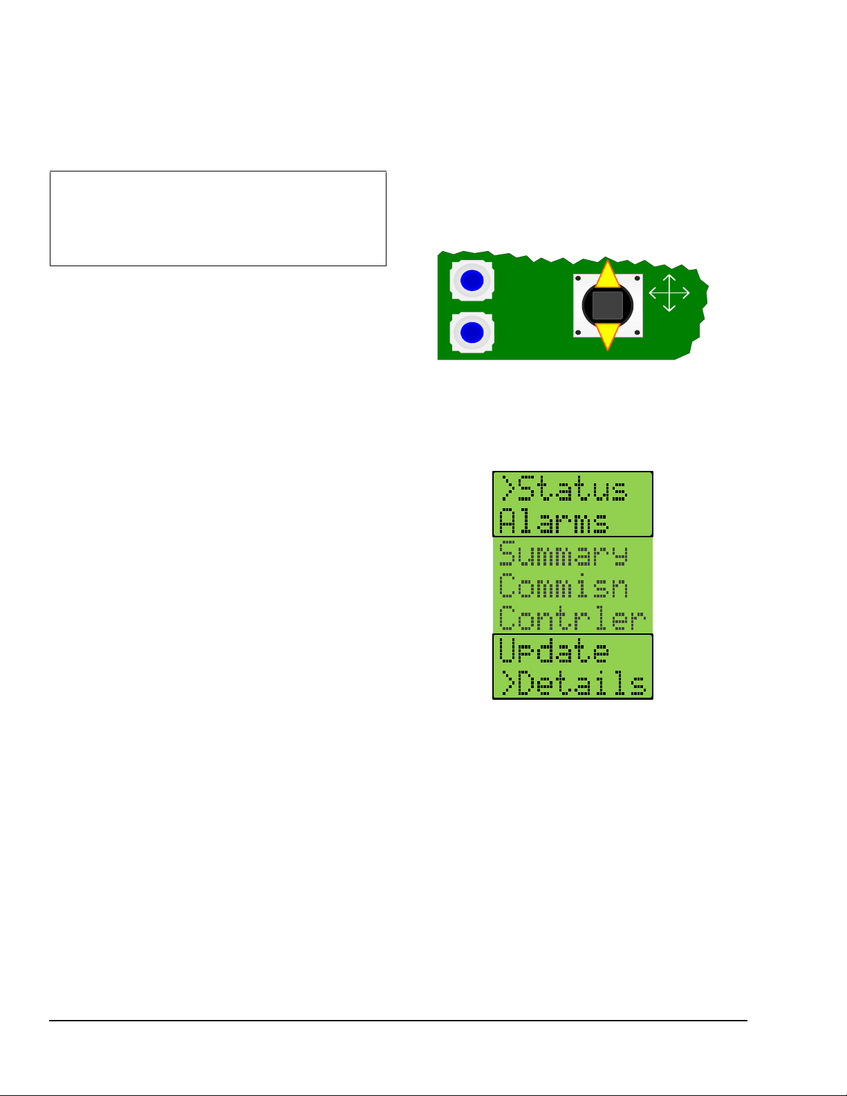
Figure 1: Joystick and Push Buttons on UCB
ENTER
CANCEL
JOY
Figure 2: UCB Top Level Menu
transformer with multiple CCS devices. Be sure that
you maintain consistent +, -, and common wiring
terminations on the shared CCS devices.
IMPORTANT: Do not interchange +, -, and
common 24 V terminations when sharing a
transformer with multiple CCS devices.
Interchanging these terminations can cause damage
to the controller.
Setup and Adjustments
To quickly set up your CCS network:
1. On each end of the 3-conductor cable, strip the
outside insulation back approximately 2 in.
(51 mm).
2. Tear off excess foil shield, leaving the bare drain
wire and the three insulated conductors.
3. On each end of the three insulated conductors in
the cable, strip the insulation back approximately
1/8 to 1/4 in. (4 to 7 mm).
4. Choose a color pattern to follow and insert each of
the three conductors into one each of the thr ee
terminals on the CCS board communication
connector.
Note: Be sure you observe polarity of each of the
conductors in the communication cable.
Communication Bus
The UCB default address is set to 4. The available
values range from 0 to 127. To view the UCB Network
Address, use the joystick and the two push buttons
below the LCD, to navigate through the menus to the
Commissioning menu (Figure 1).
Up and down movements of the joystick move the >
cursor and scroll through the selections in the active
section of the menu (Figure 2).
5. Tighten each terminal until the wire is secure.
6. Ground the drain wire at one end only of the
communication trunk. Do this on the last unit in
line.
Use an existing hole or drill a hole and insert a
sheet metal screw in the back plate below the
communication connector.
Wrap the bare drain wire around the screw and
tighten the screw. This is the only location where
the shield is grounded.
7. Daisy chain the three-conductor wire between the
remaining SPUs. Connect the drain wires together
with the wire nuts. Follow the stripping and
connecting procedure in Step 1 through Step .
8. Run the cable from the last unit to the location of
the System Manager or Zone Coordinator. Follow
the connection instructions for the System Manger
or Zone Coordinator . Figure 4 displays an example
communication riser.
9. Make sure all the SPUs are powered and operating
properly.
Each menu selection represents either a submenu or a
property. Press Enter to display the items in the
submenu or the values of the selected property.
Once you navigate to the Commissioning menu, use
the cursor to scroll to the Network submenu. From the
Address submenu, press Enter to display the current
network address. Move up or down with the joystick to
display the values of other properties.
CCS Smart Equipment Control Board for Single Packaged Unit (SPU) Controller Installation Instructions2
Page 3
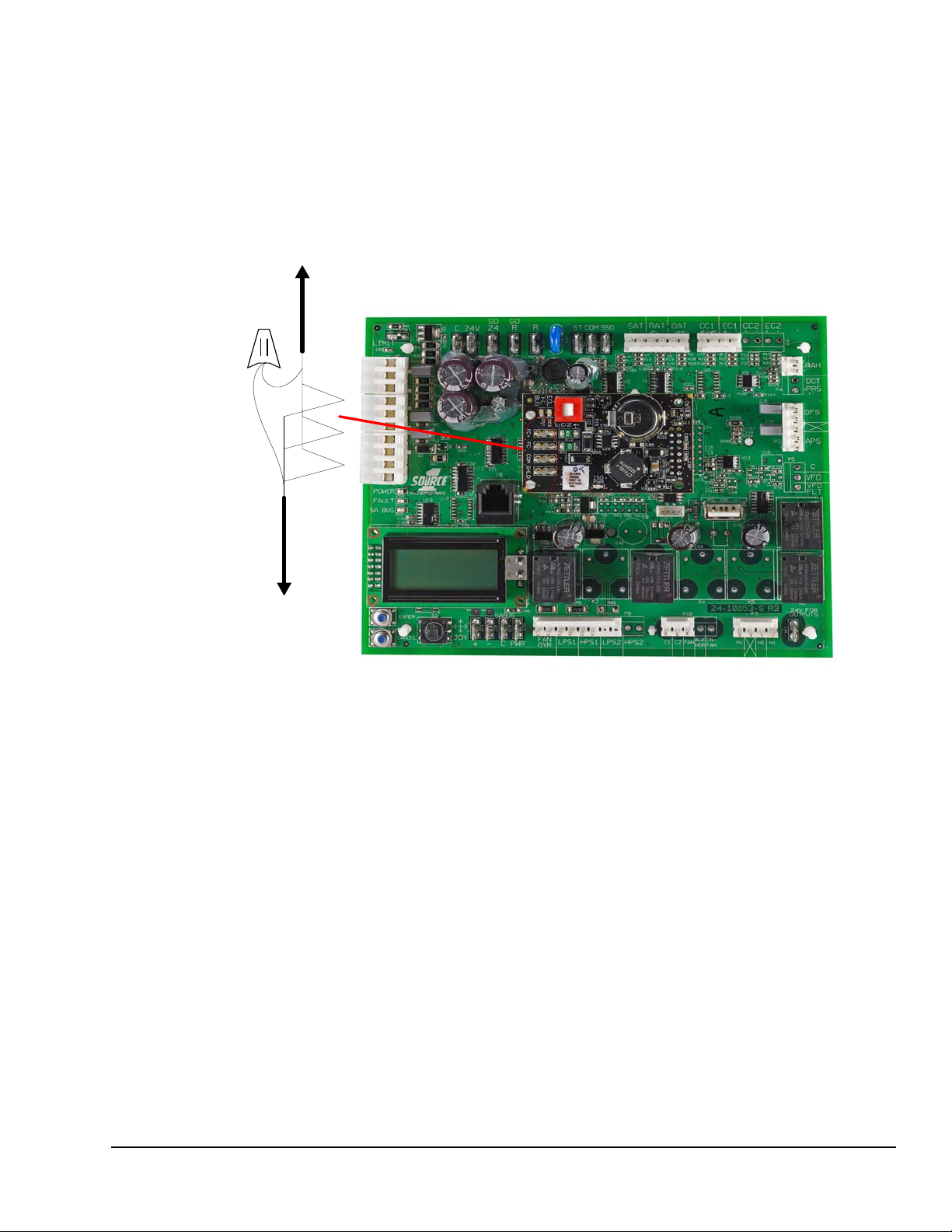
Control Board and Wiring Diagrams
Figure 3: VAV SPU Control Board Communication Terminations
Communication Cable to
Next VAV box*
Comm unication Cable to
Next VAV box, Zone
Dampers, and Bypass
Damper
* M o v e th e 4 -p ositio n te rmin al blo c k fro m th e T h e r mos ta t in pu ts
to the FC Bus connection of the communications card.
Figure 3 shows the location of the communication
cable terminations on the SPU controller board.
Figure 4 shows the VA V SPU contro ller communication
riser. .
CCS Smart Equipment Control Board for Single Packaged Unit (SPU) Controller Installation Instructions 3
Page 4

Figure 4: VAV SPU Controller - Example System Communication Riser
Optional
Inte r ne t
Connection
+
–
S
H
L
D
R
E
F
A
Earth
Ground
The shield drain wire must be earth
grounded at one and only one point for
the entire comm unication bus segment.
(Preferably at the last device)
SHIELD GROUNDING
System M anager
COM
-
+
J2
COM
AI1
AI2
COM
AI3
AI4
1
64
32
16
8
4
2
128
O
N
24VCOM24VCOM
COM
-
+
J2
1
64
32
16
8
4
2
128
O
N
Address
Swit ch
24VCOM24VCO M
COM
AI1
COM
+5V
Wir e
Nut
Observe polarity
Drain
wire
Wire
Nut
Drai n
Wire
Wire
Nut
Drain
Wire
Tape back
drain wire
Wire
Nut
Wire
Nut
Wire
Nut
Tape back
drai n wire
SEC
COBP
RTU
Address 4
Bypass
Damper
Address 5
Zone Dam per
(Typical)
Address 6
IO M
Address 4
SEC
RTU
Single Zone
Address 18
SEC RTU
Single Zone
Address 19
To additional
units and/or
any IOM
expansion
modules
To
additional
zones
O p tional R e mo te OWS
OPTIONAL SWIT CH
ETHERNET
COMM UNICATION BUS WIR E
TO BE 22AWG, 3-CONDUCTOR
TWISTED SHIELDED W IR E
WITH DRAIN.
System
Communication Bus
Zone
Communication
Bus
S1 S2
J8 J7
J6
System
Bus
Zone
Bus
CO
M
-
+
CO
M
-
+
CO
M
24V
O
n
Of
f
24VAC
COM
COM
SB
-
SB
+
ZB
+
ZB
-
COM
EOL
O
N
Of
f
EOL
O
N
S1 S2
J8 J7
J6
System
Bus
Zone
Bus
CO
M
-
+
CO
M
-
+
CO
M
24 V
O
n
Of
f
24VAC
COM
COM
SB
-
SB
+
ZB
+
ZB
-
COM
EOL
O
N
Of
f
EOL
O
N
Termination Board
System Manager
Drai n
Wir e
S
1
S
2
J
8
J
7
J
6
System
Bus
Zone
Bus
C
O
M
-
+
C
O
M
-
+
C
O
M
2
4
V
O
n
O
ff
24VAC
COM
COM
SB -
SB +
ZB +
ZB COM
EOL
ON
O
ff
EOL
ON
System
Com m unication Bus
Terminal Strip
24VAC
Power
Input (10VA)
Zone Com m unication
Bus Terminal Strip
EOL Termination
S e t T o O N
COM
-
+
J2
COM
AI1
AI2
COM
AI3
AI4
1
64
32
16
8
4
2
128
O
N
24VCOM24VCO M
COM
-
+
J2
1
64
32
16
8
4
2
128
O
N
Address
Swit ch
24VCOM24VCOM
COM
AI1
COM
+5V
SEC
VAV RTU
Address 4
VAV Box
(Typical)
Address 7
Zone
Communication
Bus
+
Termination Board
VAV Zone C oordinator
S1 S2
J8 J7
J6
System
Bus
Zone
Bus
CO
M
-
+
CO
M
-
+
CO
M
24 V
O
n
Of
f
24VAC
COM
COM
SB
-
SB
+
ZB
+
ZB
-
COM
EOL
O
N
Of
f
EOL
O
N
Termin a tion Bo a r d
COB P Zone Coordinator
Drain
wire
Tape back
drain wire
VAV Box
(Ty p ica l)
Address 6
Drai n
Wire
Wire
Nut
Drain
Wire
To
additional
zones
CCS Smart Equipment Control Board for Single Packaged Unit (SPU) Controller Installation Instructions4
Page 5

End-of-Line (EOL) Terminations
(Bounce Back and Noise)
No
EOL
EOL
Cushioning (No Bounce Back)
FIG:intrfrnc
Figure 5: Interference
Figure 6: CCS EOL Wiring Example
Input
Output
Module
24V
COM
COM-+
BI-1
COM
BI-2
COM
AI-3
COM
AI-4
Monitored Contact
To Temperature,
RH%, CO
2 Sensor,
Building Pres su re,
Light Sensor,
Refrigerant Sensor,
Common Flow
To 24VAC
BO-3
BO-2
BO-1
BO-4
COM
Monitored Contact
To Scheduled Item 1
To Scheduled Item 2
To Scheduled Item 3
To Scheduled Item 4
NonCCS
HVAC
System
Universal
CV Unit
Controller
24V
COM
Zone Sensor
COM-+
AI-1
COM
AI-2
123
4
BO-1
BO-2
BO-3
BO-4
BO-5
C
R
G
Y1
Y2
W1
W2
COM
AI-6
COM
AI-7
COM
AI-8
COM
AI-4
COM
AI-5
COM
BI-2
SAT Sensor
RAT Sensor
OAT Sensor
To Zone RH% Sensor
To Zone CO
2 Sensor
APS
COBP Zone Coordinator
System
Bus
COM
SB-
SB+
EOL
O
N
?
Zone
Bus
COM
ZB-
ZB+
EOL
O
N
?
COM
24V
LAN
To 24VAC
System Manager
System
Bus
COM
SB-
SB+
EOL
O
N
?
Zone
Bus
COM
ZB-
ZB+
EOL
O
N
?
COM
24V
Modem
LAN
To 24VAC
To Phone Line
To Ethernet Hub
VAV Zone Coordinator
System
Bus
COM
SB-
SB+
EOL
O
N
?
Zone
Bus
COM
ZB-
ZB+
EOL
O
N
?
COM
24V
LAN
To 24VAC
tape
off
SEC Unit Control Board
COM-+
This end of the Drain Wire
connected to cabinet ground
Other System Bus Devices
CCS System Bus Devices
Other System Bus Devices
Other System Bus Devices
To COBP Zone
Bus Devices
To VAV Zone
Bus Devices
Recommended ZC e nd-of-line for zone bus
Recommended S M end -of-line for system bus
Must be end of line for zone bus
TEC2601-4
TEC2602-4
TEC2603-4
Y2
Y1
G
RC
C
RH
W1
W2
Aux
DI1
DI2
RS
Scom
OS
MS
+
_
Ref
COM-+
Daisy-chained RS485 protocol networks require
end-of-line (EOL) termination to reduce interference.
Interference is caused by signal reflection that occurs
when data transmissions reach the end of a bus
segment and bounce back (Figure 5). The high baud
rates on Master-Slave/Token-Passing (MS/TP) bus
applications require robust EOL termination and strict
adherence to the EOL termination rules.
On a CCS System bus or Zone bus, only one EOL
termination is required due to the fewer number of
devices on one bus and the shorter wiring length.
Specifically, the System bus must always have a
System Manager as the EOL device, and the Zone bus
must always have a Zone Coordinator as the EOL
device. Figure 6 shows a CCS EOL wiring example.
No EOL = No Signal Cushioning
EOL Provides Signa l
CCS Smart Equipment Control Board for Single Packaged Unit (SPU) Controller Installation Instructions 5
Page 6

Operation
Figure 7: Startup Countdown
The controllers are supplied in a pre-configured format.
Y ou do not n eed to configure the controller. Refer to the
Commercial Comfort System (CCS) Operation
Overview Technical Bulletin (LIT-12011617) or the
Smart Equipment Controls (SEC) Quick Start Guide
(LIT-12011938) for information on operating modes and
functionality.
Troubleshooting
Use the following information to troubleshoot the
System Manger and Zone Coordinator.
Power Status LED
The display backlight and green Power LED remain lit
as long as power is applied to the C and 24V terminals.
The red Fault LED lights, goes off briefly, and then
flashes throughout the startup sequence.
The green SA Bus LED lights briefly.
During the startup sequence, the joystick, the Enter
button, and the Cancel button are not functional.
The LCD shows a countdown on the top line.
After the startup sequence finishes, the display shows
XxXx on both lines if no alarm is active. The red Fault
LED stops flashing and turns off. The joystick, Enter,
and Cancel buttons are operational.
Communication Bus Problems
Several factors may influence the behavior of the
communication bus. In addition, certain proble ms can
affect the bus in multiple ways and have multiple
symptoms, which makes the exact diagnosis difficult.
For example, duplicate addresses on the bus can
degrade performance, make the device go offline, or
stop communication completely.
Incomplete Address
With the SEC controller for VAV, COBP must have the
address switch set to 4 on the zone communication
bus. Other settings prevent the SPU from
communicating on the System Communication bus.
Duplicate Addresses
Two or more devices on a communication bus cannot
have the same address. For example, two SPUs on the
System communication bus cannot both have the
address 4. If two devices on the same bus have the
same address, performance can degrade or serious
communication problems may occur. These problems
include the devices not coming online or all
communication stopping completely.
After approximately 15 seconds, the green SA Bus
LED does one of the following:
• Lights to indicate the UCB has not established
communication and is awaiting communication
from SA Bus devices
• Flashes to indicate the UCB established
communication with SA Bus devices
Check for duplicate addresses in the following ways
depending on the severity of the situation:
• If the bus performance is degraded, check the
address switch settings at the devices with
unreliable communications.
• If a specific device is not communicating, remove
the device with communication problems and
check if the device address remains online at the
System Manager or Zone Coordinator.
• If the bus communication problems are severe,
and no communication is present (or if you cannot
determine where communication is unreliable),
partition (disconnect and isolate a portion of the
bus for testing purposes) and test the bus portion
connected to the System Manager and Zone
Coordinator controllers.
CCS Smart Equipment Control Board for Single Packaged Unit (SPU) Controller Installation Instructions6
Page 7

Correcting Physical Communication Bus Problems
The communication bus is subject to a number of
physical factors that can affect performance. Consider
the following list of common physical problems that
affect the communications bus:
• Check wires
- Verify that the wire is 22 AWG (0.65 mm) 3conductor, twisted, shielded cable.
- Verify that the shield is continuous and hardgrounded at one end.
• Check wiring
- Check for and eliminate T-Taps (wire
configurations that create a T shape) and star
configurations.
- Ensure that the bus is wired in daisy-chain
fashion.
- Verify that appropriate devices have three
wires entering and exiting each terminal.
(Devices at the ends of the trunk do not have
this wiring.)
• Check EOL switch settings
- Verify that the zone bus EOL switch on the
Zone Coordinator is set to ON and the Zone
Coordinator is located at the end of the zone
bus trunk.
- Verify that only the EOL switch at the end of
the system bus is set to ON and all other
system bus EOL switches are set to OFF.
• Check connections, polarity, and lengths
- Verify that communica tions loop s ar e less th an
approximately 304 m (1,000 ft) total in length
- If you are using one transformer to power
multiple devices, verify that the device 24 VAC
power connection follows the polarity of the
common and 24 V terminations (see Power
Wiring).
• Check for opens and shorts
• Check terminations
• Check addresses
- Check for duplicate addresses.
- Verify that the address range is sequential.
• Check for sources of interference
• Check the status LED to verify power at the
controller.
• Check bus voltages:
- (+) to COM must be within 2.0 to 3.0 VDC
- (-) to COM must be within 1.5 to 2.54 VDC
- (+) to (-) must be within 0.3 to 1.0 VDC
Note: Values may fluctuate due to ongoing
communications; this operation is normal provided
the voltage is within the defined range.
Repair Information
If the Unit Control Board (UCB) fails to operate within
its specifications, replace the unit. For a replacement
controller, co ntact the nearest Johnson Controls®
representative.
CCS Smart Equipment Control Board for Single Packaged Unit (SPU) Controller Installation Instructions 7
Page 8

Metasys® and Johnson Controls® are registered trademarks of Johnson Controls, Inc.
All other marks herein are the marks of their respective owners. © 2015 Johnson Controls, Inc.
Building Efficiency
507 E. Michigan Street, Milwaukee, WI 53202
Technical Specifications
Unit Control Board with BACnet® Communication
Product Code Number SE-SPU1011-1 – Single-stage Unit Control Board with Field Bus Expansion Module
SE-SPU1012-1 – Dual-stage Unit Control Board with Field Bus Expansion Module
Power Supply Requirement 24 VAC (nominal, 20 VAC minimum/30 VAC maximum), 50/60 Hz, Power Supply
Class 2 (North America), Safety
Power Consumption 15 VA maximum
Note: VA ratings do not include any power supplied to the peripheral devices connected
to binary outputs (BOs)
Ambient Conditions Operating: -40 to 158°F (-40 to 70°C); 10 to 90% RH noncondensing
UI Operating: -4 to 158°F (-20 to 70°C); 10 to 90% RH noncondensing
Storage: -40 to 194°F (-40 to 85°C); 5 to 95% RH noncondensing
Processor RX631 Renesas® microcontroller
Memory 2 MB internal program flash, 32 KB internal E2Data flash, 4 MB external serial flash
Input and Output Capabilities SE-SPU1011-1:
Housing Unpackaged printed circuit board (PCB) with silkscreen labels
Mounting Mounted with Nylon Standoffs
Dimensions
(Height x Width x Depth)
Shipping Weight SE-SPU1011-1 – 3.6 lb (1.63 kg)
Compliance United States:
memory
9 AIs: 7: 10k RTD, 1: 0 to 10 VDC, 1: 24 VAC Voltage Monitor
13 BIs: 24 VAC input with contact cleaning circuits
5 BOs: 4: relay outputs, 1: Transistor output
SE-SPU1012-1:
12 AIs: 9: 10k RTD, 2: 0 to 10 VDC, 1: 24 VAC Voltage Monitor
1 AOs: 2 to 10 VDC, 10 mA maximum
16 BIs: 24 VAC input with contact cleaning circuits
8 BOs: 7: relay outputs, 1: transistor output
1.44 x 6.5 x 5.27 in. (36 x 165 x 133 mm)
SE-SPU1012-1 – 3.7 lb (1.68 kg)
UL Recognized, File E107041, UL 916, Energy Management Equipment, UL1995,
Heating and Cooling Equipment; FCC Compliant to CFR47, Part 15, Subpart B, Class B
Canada:
UL Recognized, File E107041, CSA 22.2 No. 236, Signal Equipment Industry Canada,
ICES-003 – Recognized
CCS Smart Equipment Control Board for Single Packaged Unit (SPU) Controller Installation Instructions8
Published in U.S.A. www.johnsoncontrols.com
 Loading...