

Page 1

SETRA
OPERATING INSTRUCTIONS
SERIES DPT 209
PRESSURE TRANSDUCERS
1.0 GENERAL INFORMATION
Every Model DPT209 has been tested and calibrated before shipment.
Setra Systems DPT209 pressure transducers sense gauge pressure and convert this pressure
difference to a proportional high level analog output. Three standard output and excitation
versions are offered:
Excitation Output
9 to 28 VDC 4 to 20mA – (Must Observe Polarity)
9 to 30 VDC 0.5 to 5.5 VDC – (Reverse Excitation Protection)
4.9 to 8.1 VDC 0.5 to 4.5 VDC – (No Reverse Wire Protection)
2.0 MECHANICAL INSTALLATION
2.1 Media Compatibility
Model DPT209 transducers are designed to be used with any gas or liquid compatible with 17-4 PH
stainless steel. Never totally submerge the unit in any liquid.
2.2 Environment
The operating temperature limits of the DPT209 are –40° to +185°F (-40 to +85°C). The
compensated temperature range is –4 to +176°F (-20 to +80°C)
2.3 Pressure Fittings
Typically, standard pipe fittings should be used. However, for pressure ranges in excess of 500 psig,
we suggest the use of a sealant such as Loctite Hydraulic Sealant. Excessive torquing of metal
fittings may cause a slight zero shift. The use of plastic fittings typically results in no noticeable
zero shift. Torquing does not appreciably affect linearity or sensitivity.
2.4 Tube Stub Welding Instructions
Standard welding practices should be followed. Caution must be taken to protect the sensor against
current paths that could damage the circuit board. Apply a heat sink between the weld zone and
the sensor that is large enough to protect the sensor from overheating. Failure to use a heat sink
may damage the housing seal or circuit board.
2.5 Venting
Because the reference pressure in a sealed gage transducer will vary due to changes in
temperature and will affect overall accuracy (especially in units of less than 500 psig range), all
DPT209 Series transducers are available as vented or sealed to atmosphere.
Vented units are ordered as PSIG ranged units. Sealed units are ordered as PSIS range units. The
DPT209 PSIG transducers are vented through the cable. Hirschmann PSIG transducers are vented
through the connector. Packard PSIG units are vented through a porous filter plug supplied on the
unit.
3.0 ELECTRICAL INSTALLATION
The Model DPT209 is available in four electrical terminations:
1. Two foot Cable
2. Packard Connector
3. Hirschmann Connector
4. Conduit Adapter, 1/2 inch
Page 2
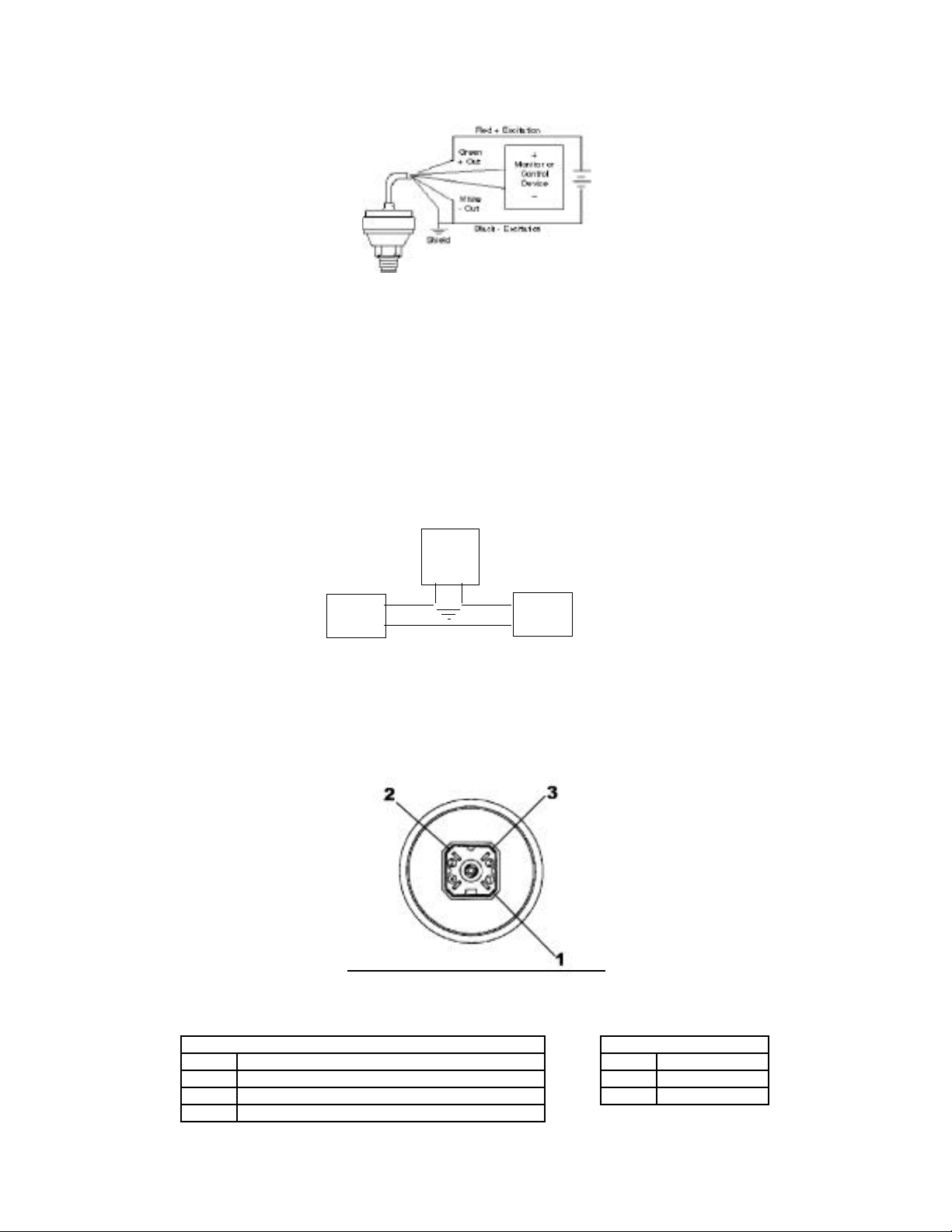
3.1 Voltage Output Units
black
The Model DPT209 voltage output is a 3-wire circuit. If the DPT209 is supplied with 2 feet of
cable, the electrical connection is as follows:
Red = + Excitation; connect to appropriate power supply
Green = + Output; connect to controls or monitor.
Black = Common; connect to return of power supply.
White = -Output; connect to controls or monitor.
Shielding = Connected to system or earth ground.
3.2 Current Output Units
The Model DPT209 (current output) transducer is a true 2-wire, 4-20 mA current output device and
delivers rated current into any external load of 0-800 ohms. The 4-20 mA current output units are
designed to have current flow in one direction only - PLEASE OBSERVE POLARITY. We suggest
that the electrical cable shield be connected to the system’s loop circuit ground to improve
electrical noise rejection. The electrical connection is as follows:
Model C209
Setra
Transmitter
(4-20 mA)
red +
Power Supply
The DPT209 has a 2-wiere cable, where red is positive and black is negative.
_ _
_
+
++
Load
(Monitor)
3.3 Hirschmann or Packard Connectors – Voltage and Current Output
If the unit is provided with a Hirschmann or a Packard Connector, pin number designation are as
follows:
Hirschmann Connector
Top View: Hirschmann Connector
Type: G4A1M#931807-106
Voltage Output Current Output
Pin # Function Pin # Function
1 + Excitation (connect to appropriate power supply 1 Positive
3 + Output (connect to controls or monitor 2 Negative
2 Common (connect to return of power supply)
Page 3

3-Pin Packard Connector
Voltage Output Current Output
Pin # Function Pin # Function
B + Excitation (connect to appropriate power supply B Positive
C + Output (connect to controls or monitor A Negative
A Common (connect to return of power supply)
4-Pin Packard Connector
Top View: 3-Pin Packard Connector
Type: P25 Series 150
Top View: 4-Pin Packard Connector
Type: Metri-Pack 150
Voltage Output Current Output
Pin # Function Pin # Function
A + Excitation (connect to appropriate power supply A Positive
C + Output (connect to controls or monitor B Negative
B Common (connect to return of power supply)
D (Not Used
Setra does not supply the mating connectors as a standard. They can be ordered separately.
Consult Factory.
Page 4

3.4 Conduit Adapter Electrical Termination – Voltage and Current Output Units
If the unit is provided with the conduit adapter version, terminal designations are as follows:
Conduit Adapter Version
(Voltage and Current Output Units)
For current (4-20 mA) output use + and – terminals
For voltage output, use COM, OUT, and EXC terminals
3.5 Conduit Fitting Installation
1. Connect the pressure port to the system.
2. Install a 1/2” conduit fitting into the DPT209 top cover and fasten the retaining nut.
3. Feed wires from a flexible conduit through the DPT209 top cover; fasten the wires to terminals.
4. Screw on the Model DPT209 top cover.
5. Fit conduit into conduit fitting and tighten conduit watertight strain relief.
3.6 EMC Certification
This product complies with EN61326 Electrical Equipment for Measurement Control and
Laboratory use – EMC Requirements for Minimum Requirements and Industrial Locations. Special
caution should be taken to meet Standard EN61000-4-5: 1995 Surge Immunity if any of the
following conditions apply to the installation: the product is installed outside; all or any part of the
cable is exposed to the outside; the cable is greater than 30 meters in length. In order to meet the
CE Surge Immunity requirements, the following conditions must be followed during installation:
1. Shielded cable must be used, and the shield must be tied to earth ground (not
power supply ground) on at least one end of the cable shield/drain wire. The shield
must be maintained all the way from sensor to the power supply.
2. If unshielded cable is used, an earth grounded metal conduit should be used to
replace the shielded cable.
3. For a sensor with a metal body or enclosure, the body/enclosure must be grounded
to earth. If a protective metal housing is used, the housing must be able to
withstand at least 2 kV from the housing to earth ground without damaging the
circuit.
 Loading...