

Page 1
SEN-600-1 and SEN-600-4 Remote Indoor Temperature
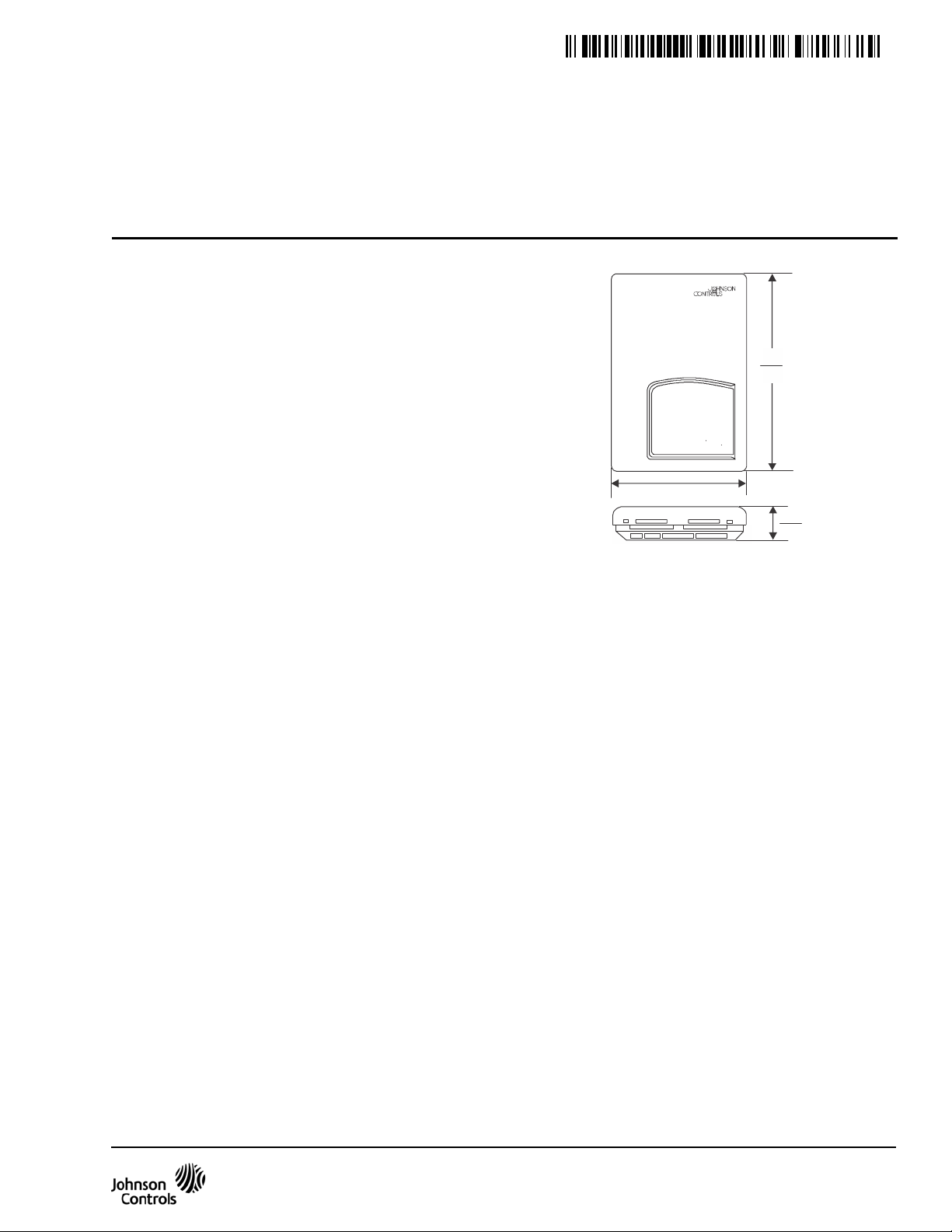
Figure 1: Sensor Dimensions, in./mm
125
86
29
24-9954- 7, Rev. B
Sensors
Installation Instructions
Refer to the QuickLIT website for the most up-to-date version of this document.
Application
The SEN-600-1 and SEN-600-4 remote sensors are
designed to allow remote indoor temperature sensing in
applications with the T600 Series programmable and
non-programmable thermostats and the
TEC2000 Series Network Thermostats. The
SEN-600-1 and SEN-600-4 contain an integral sensor
and circuitry to interface with the T600 and
TEC2000 Series Thermostats. Additionally, the
SEN-600-4 has an override button and Light-Emitting
Diode (LED) indicator to enable and indicate
occupancy override from the remote sensor. Up to
three remote sensors can be wired together for
averaging.
Note: The SEN-600-4 remote indoor sensor is only
intended for use with programmable T600 Series
thermostats. Additionally, if the SEN-600-4 is used with
a T600 non-programmable thermostat, the LED does
not light up to indicate occupancy status.
Mounting
Prior to installing the sensor, install the T600 or
TEC2000 Series Thermostat following the installation
instructions provided with the thermostat.
Location Considerations
Locate the sensors as follows:
• on a partitioning interior wall, and approximately 5 ft
(1.5 m) above the floor in a location of average
temperature
• away from direct sunlight, radiant heat, outside
walls, behind doors, air discharge grills, stairwells,
or outside doors
Part No. 24-9954-7, Rev. B
Issued March 2016
Installation
4.94
3.38
1.13
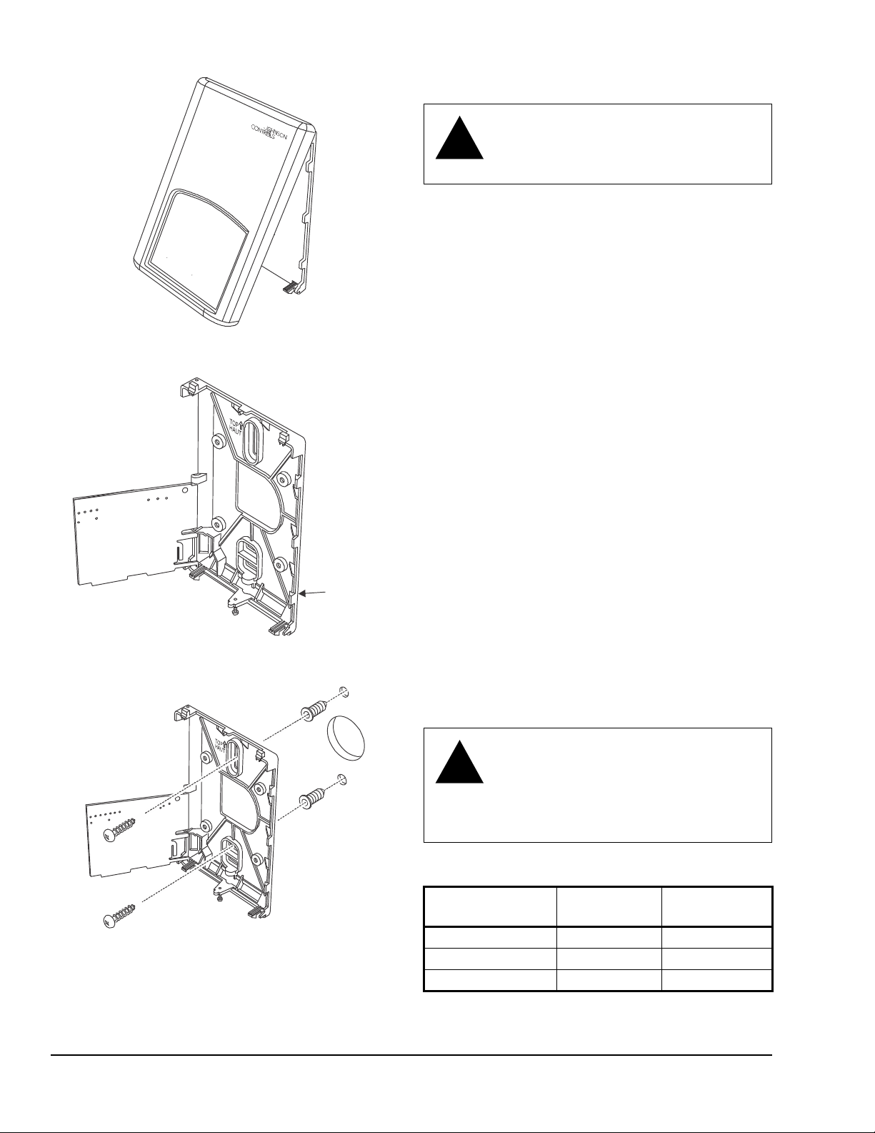
To install the sensor:
1. Remove the security screw on the bottom of the
sensor cover using a Phillips-head screwdriver.
Open the thermostat by pulling on the bottom side
of the sensor cover (see Figure 2).
2. Unlock the Printed Circuit Board (PCB) by carefully
pressing the locking tabs to the right. Open the
sensor’s PCB to the left (see Figure 3).
3. Pull out approximately 6 in. (152 mm) of wires from
the wall and insert the cable through the hole in the
base.
4. Align the base on the wall, and using the base as a
template, mark the location of the two mounting
holes on the wall. Confirm the sensor base is
installed with the proper side up.
• away from steam or water pipes, warm air stacks,
unheated/uncooled areas, or sources of electrical
interference
5. Use the supplied anchors and screws for mounting
on drywall or plaster. Drill two 3/16 in. (4.7 mm)
holes at the marked locations and tap nylon
anchors flush to wall surface (see Figure 4).
6. Position base on the wall, insert screws through
mounting base, and fasten into wall anchors. Do
not overtighten screws.
7. Swing the sensor’s PCB back to the right to close.
Gently press on the PCB to secure the locking tab.
SEN-600-1 and SEN-600-4 Remote Indoor Temperature Sensors Installation
Instructions
1
Page 2
Wiring
!
!
Figure 2: Removing the Sensor Cover
Figure 3: Opening the Sensor PCB
Figure 4: Mounting the Sensor Base
CAUTION: Risk of Electric Shock.
Disconnect the power supply before
making electrical connections to avoid
electric shock.
Note: Keep sensor conductors as short as possible to
minimize temperature error. If necessary, the indoor
temperature displayed at the thermostat can be
adjusted (refer to the appropriate T600 or
TEC2000 Series Installation Instructions).
To wire the sensor:
1. Connect wires between the T600 or
TEC2000 Series thermostat and the SEN-600-1 or
SEN-600-4 sensors according to the appropriate
wiring diagram (see Figure 5).
2. Set the switch on the PCB in the remote indoor
sensor to the correct positions (see Table 1 for
switch positions).
3. Reattach the sensor cover to the installed bas e
(top side first) and install the security screw on the
bottom.
PCB
Locking Tab
4. Verify that the sensor is functioning by checking the
temperature display on the T600 or
TEC2000 Series thermostat. If using the
SEN-600-4 remote sensor, verify the functionality
of the override button and occupancy status LED.
Note: If using the SEN-600-4, the digital input on the
thermostat to which the D1 terminal on the sensor is
connected must be configured for remote override
(RemOVR). Refer to the appropriate T600 Installation
Instructions for details on configuring the digital input.
CAUTION: Risk of Property Damage.
Do not apply power to the system before
checking all wiring connections. Short
circuited or improperly connected wires
may result in permanent damage to the
equipment.
Table 1: Switch Positions for Single or Multiple
Sensor Installations
Number of
Sensors
1 Sensor On On
2 Sensors Off On
3 Sensors Off Off
Switch 1 Switch 2
SEN-600-1 and SEN-600-4 Remote Indoor Temperature Sensors Installation Instructions2
Page 3

Figure 5: Wiring Diagrams
AUX
C
D1
AU
AUX
C
D1
RS
Scom
RS
Scom
AU
C
D1D2
T600 or TEC2000 Series
RS
Scom
AUX
C
D1
RS
Scom
AU
C
D1D2
RS
Scom
SEN-600-1
SEN-600-4
T600
This is a wiring example of two remote room sensors for averaging applications (S1=Off, S2=On).
Note: Whe n w i r ing the S E N- 600-4 remote indoor sensor to
a non-programmable model of the T600, the AUX terminal
on the SEN-600- 4 is not us ed. Addition al ly, when using the
SEN-6 00-4 remo t e indoor sensor wit h a non-programmable
model of the T600, the LED does not light to indicate
occupancy status.
This is a wiring example of a single remote room sensor (S1=On, S2=On).
RS
Scom
AUX
C
D1
RS
Scom
AU
C
D1D2
T600
RS
Scom
RS
Scom
AU
C
D1D2
T600 or TEC2000 Series
SEN-600-1
This is a wiring example of three remote room sensors for averaging applications (S1=Off, S2=Off).
T600
AU
C
AUX
C
D1
SEN-600-1
SEN-600-4
SEN-600-1
AUX
C
D1
AUX
C
D1
AU
T600 or TEC2000 Series
AU
C
AUX
C
D1
AU
C
TEC2x45-4
This is a wiring example of a single remote room sensor for TEC2x45-4 applications (S1=On, S2=On).
IMPORTANT:
The SEN-600-1 is not compatible
with TEC2x45-4 thermostat models. On
SEN-600-4 sensors, only the remote override
function is compatible with TEC2x45-4 thermostat
models.
SEN-600-4
SEN-600-1
RS
Scom
SEN-600-1SEN-600-1
D2
RS
Scom
D1
RS
Scom
RS
Scom
RS
Scom
RS
Scom
D1D2
RS
Scom
T600
RS
Scom
SEN-600-1
RS
Scom
C
D1D2
T600
RS
Scom
SEN-600-1
RS
Scom
RS
Scom
C
D1D2
SEN-600-4 S E N-600-4
RS
Scom
RS
Scom
SEN-600-4 SEN-600-4
RS
Scom
RS
Scom
SEN-600-1
RS
Scom
D1D2
SEN-600-1 and SEN-600-4 Remote Indoor Temperature Sensors Installation Instructions 3
RS
Scom
SEN-600-4
Page 4

Troubleshooting
Table 2: Troubleshooting
Symptom Possible Cause Corrective Action
Temperature displayed at the T600 or
TEC2000 Series does not correlate
with the temperature at the remote
sensor.
Override button on SEN-600-4
remote sensor is not functional.
Remote LED is not functional on the
SEN-600-4 remote sensor.
Remote sensor is not correctly
connected.
T600, TEC2000 Series, or remote
sensor has failed.
SEN-600-4 is incorrectly wired to the
thermostat.
The appropriate digital input on the
thermostat is not configured to remote
override (RemOVR).
SEN-600-4 is incorrectly wired to the
thermostat.
The auxiliary output is not properly
configured at the T600 programmable
thermostat.
The T600 Series thermostat to which
the SEN-600-4 is connected is not a
programmable model.
Check wiring connections at the
thermostat terminal blocks and
between the thermostat and the remote
sensor.
Short the appropriate sensor terminals
at the thermostat. The display should
indicate 122ºF (50ºC). If the reading is
not 122ºF (50ºC), replace the
thermostat. If the reading is 122ºF
(50ºC), check the resistance across the
sensor with the wires removed from the
thermostat. The resistance should be
10,000 ohms at 77ºF (25ºC). If the
resistance is not correct, replace the
sensor.
Check wiring connections with the
corresponding digital input at the
thermostat, at the D1 terminal on the
remote sensor, and between the
thermostat and remote sensor.
Configure the appropriate digital input
at the thermostat for remote override
(RemOVR). Refer to the appropriate
T600 Installation Instructions for
details.
Check wiring connections at the
auxiliary output at the programmable
T600 thermostat, at the AUX terminal
on the remote sensor, and between the
thermostat and remote sensor.
Configure the auxiliary output at the
T600 programmable thermostat for
Normally Open (N.O.). Refer to the
appropriate T600 Installation
Instructions for details.
The LED does not indicate occupancy
status on non-programmable T600
models (there is no auxiliary contact at
the thermostat). Replace the T600 with
a programmable model.
SEN-600-1 and SEN-600-4 Remote Indoor Temperature Sensors Installation Instructions4
Page 5

Metasys® and Johnson Controls® are registered trademarks of Johnson Controls, Inc.
All other marks herein are the marks of their respective owners. © 2016 Johnson Controls, Inc.
Building Efficiency
507 E. Michigan Street, Milwaukee, WI 53202
Technical Specifications
SEN-600-1 and SEN-600-4 Remote Indoor Temperature Sensors
Power Requirements Supplied by the T600 or TEC2000 Series Thermostat
Sensor Accuracy ±0.9 Fº from 32 to 158ºF; ±0.5 Cº from 0 to 70ºC
Sensor Ambient Operating
Conditions
Sensor Ambient Storage
Conditions
Dimensions (H x W x D) 4.94 x 3.38 x 1.13 in. (125 x 86 x 29 mm)
Shipping Weight 0.75 lb (0.34 kg)
The performance specifications are nominal and conform to acceptable industry standards. For application at conditions beyond these
specifications, consult the local Johnson Controls® office. Johnson Controls, Inc. shall not be liable for damage resulting from misapplication or
misuse of its products.
European Single Point of Contact: NA/SA Single Point of Contact: APAC Single Point of Contact:
JOHNSON CONTROLS
WESTENDHOF 3
45143 ESSEN
GERMANY
32 to 122ºF (0 to 50ºC); 0 to 95% RH noncondensing
-22 to 122ºF (-30 to 50ºC); 0 to 95% RH noncondensing
JOHNSON CONTROLS
507 E MICHIGAN ST
MIL WAUKEE WI 53202
USA
JOHNSON CONTROLS
C/O CONTROLS PRODUCT
MANAGEMENT
NO. 22 BLOCK D NEW DISTRICT
WUXI JIANGSU PROVINCE 214142
CHINA
SEN-600-1 and SEN-600-4 Remote Indoor Temperature Sensors Installation Instructions 5
Published in U.S.A. www.johnsoncontrols.com
 Loading...