

Page 1
System 350™
S350A Temperature, S351A Humidity,
and S352A Pressure Stage Modules
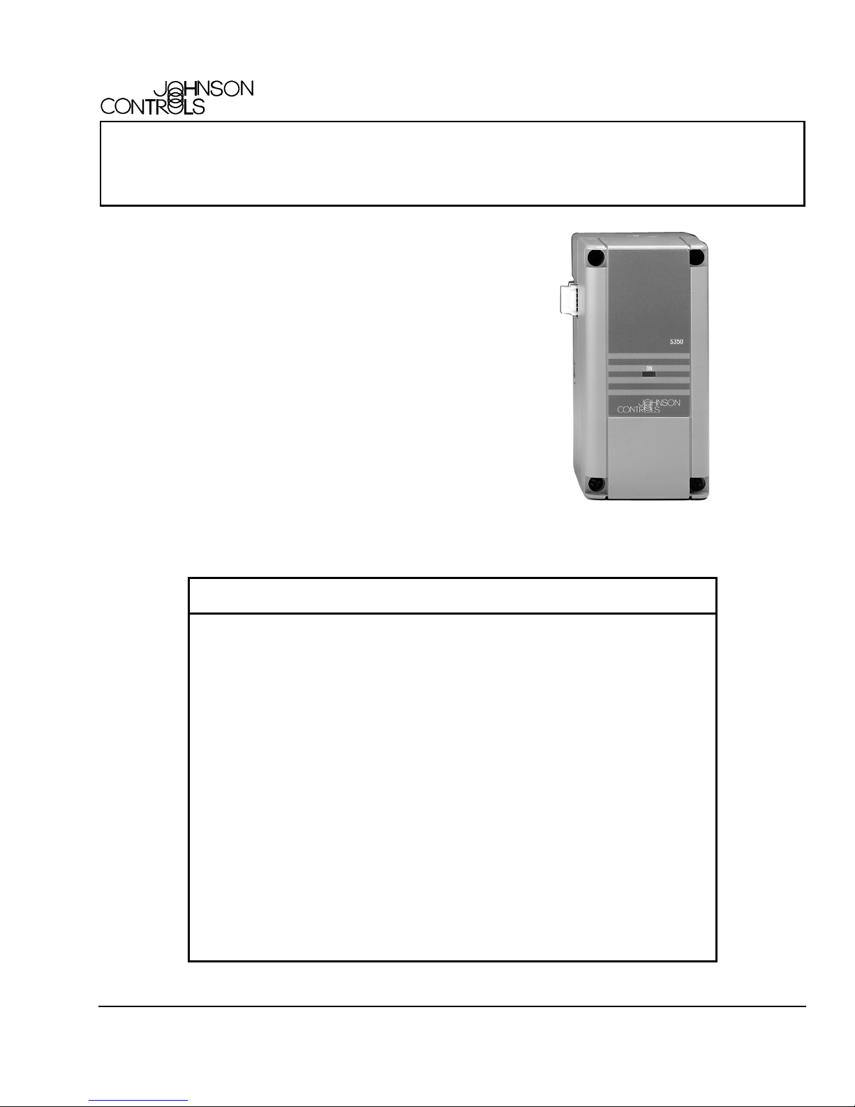
The S350A, S351A, and S352A Stage Modules are
intended to be used with System 350™ controls. Each
of these stage modules plugs into the respective
control module to add multiple-stage capability. These
stage modules have Single-Pole, Double-Throw
(SPDT) relay output with Light-Emitting Diode (LED)
indication.
As are all System 350 products, the stage modules are
housed in NEMA 1, high-impact thermoplastic
enclosures. The modular design provides easy,
plug-together connections for quick installation and
future expandability.
FANs 930, 125
Product/Technical Bulletin S350
Issue Date 0300
Modular Design
❑
Plug-together Connectors
❑
and 35 mm DIN Rail
Mounting
Selectable Mode of
❑
Operation
Adjustable Differential
❑
Adjustable Offset
❑
Figure 1: System 350 Stage Module
Features and Benefits
Permits system to be configured to
equipment, with convenient, future expansion
made easy
Eliminates wiring between modules and
reduces installation costs
Provides independent relay energization,
either above or below setpoint, for
cooling/heating (S350A),
dehumidification/humidification (S351A), or
direct acting/reverse acting (S352A)
Enables user to match the range of
temperature, humidity, or pressure stage
modules to specific application requirements
Allows multiple stage sequencing of 1-30F°
(0.5-17C°) (S350A), 2-30% RH (S351A), or
2-50 psi (S352AA-2)
© 2000 Johnson Controls, Inc.
Part No. 24-7664-1, Rev. D www.johnsoncontrols.com
Code No. LIT-930080
1
Page 2
pplication
A
The S350A, S351A, and S352A Stage Modules
receive power, setpoint, and sensor input from the
respective System 350 control modules. When
connected, the individual modules act as a multistage
control system.
The maximum number of stages that can be used in a
system varies with the control module type
(temperature, humidity, or pressure) and stage module
design.
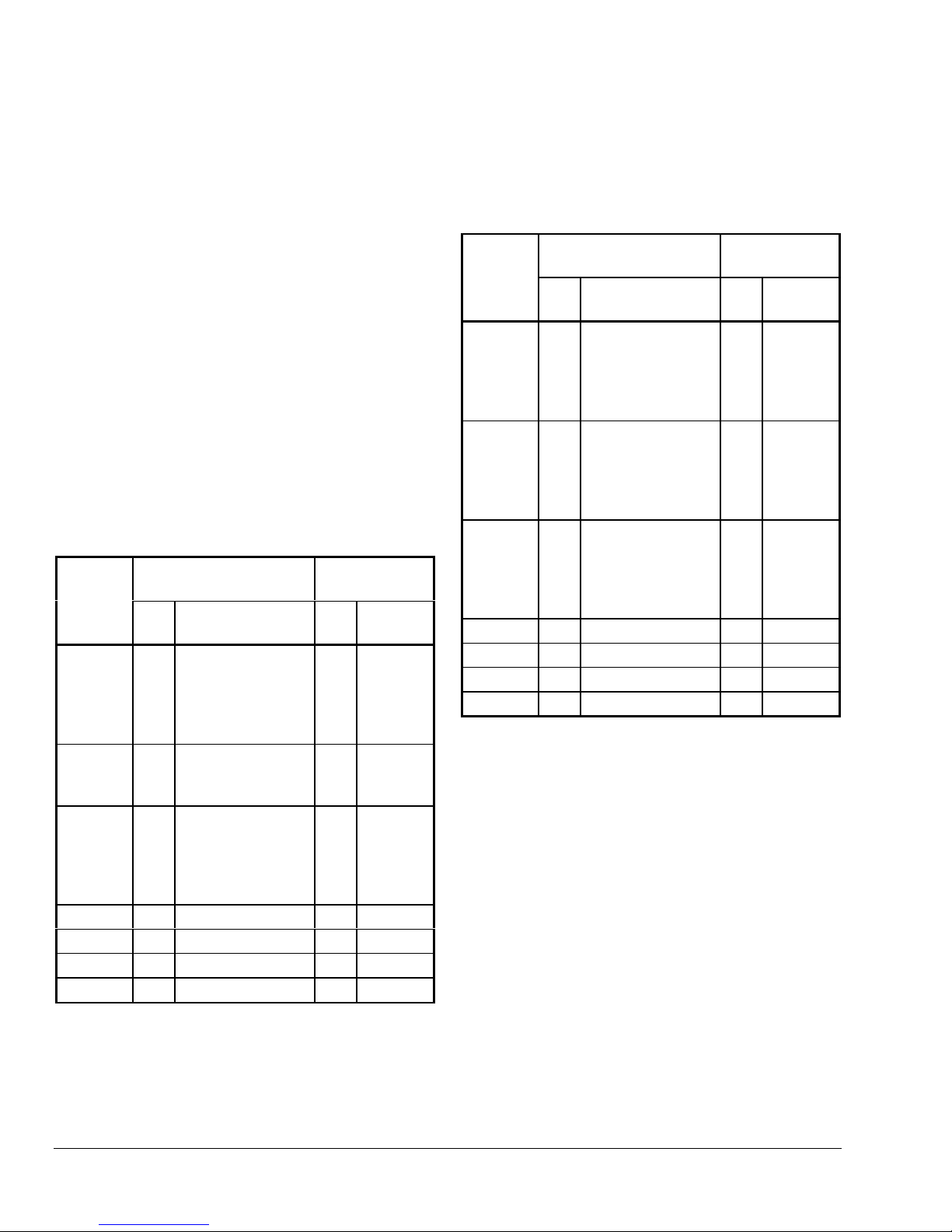
Refer to Table 1 or Table 2 to determine the maximum
number of stages that may be used with each control
module. When mixing stage module designs, always
use the lower number.
Note: When using an external transformer, the
Y65 Series or other 40 VA Class 2
transformers are recommended.
Table 1: Maximum Number of Add-on
Modules when Powered by a Y350R
Power Module
Control
Module
A350A
A350B
A350E
A350P
A350R
A350S
W351A
W351P
P352AB
P352PN
Stage
Module
No. Model
Numbers
9
S350As or S350Cs
6
S350As or S350Cs
with 1 S350P
S350As or S350Cs
4
with 2 S350Ps
42S350As or S350Cs
S350As or S350Cs
with 1 S350P
9
S350As or S350Cs
6
S350As or S350Cs
with 1 S350P
S350As or S350Cs
4
with 2 S350Ps
5 S351As 1 D351
4 S351As 1 D351
5 S352As 1 D352A
4 S352As 1 D352A
Display
Module
No. Model
Number
1 D350
1 D350
2 D350s
Table 2: Maximum Number of Add-on
Modules when Powered by an External
Transformer
Control
Module
Stage
Module
No. Model
Numbers
A350A
A350B
A350E
A350P
A350R
A350S
W351A
W351P
P352AB
P352PN
9
S350As or S350Cs
8
S350As or S350Cs
with 1 S350P
S350As or S350Cs
7
with 2 S350Ps
9
S350As or S350Cs
8
S350As or S350Cs
with 1 S350P
S350As or S350Cs
7
with 2 S350Ps
9
S350As or S350Cs
8
S350As or S350Cs
with 1 S350P
S350As or S350Cs
7
with 2 S350Ps
9 S351As 1 D351
9 S351As 1 D351
9 S352As 1 D352A
9 S352As 1 D352A
Notes: This bulletin only refers to the S350A, S351A,
and S352A Stage Modules.
For information on the S350C refer to the
System 350
TM
S350C Temperature Slave
Stage Module Product/Technical Bulletin
(LIT-930084).
For information on the S350P refer to the
System 350
TM
S350P Proportional Plus
Integral Temperature Stage Module
Product/Technical Bulletin (LIT-930086).
For information on the D350, D351 and D352
refer to the
System 350
TM
D350 Display
Modules Product/Technical Bulletin
(LIT-930070)
.
Display
Module
No. Model
Number
1 D350
1 D350
2 D350s
2
S350A Temperature, S351A Humidity, and S352A Pressure Stage Modules Product/Technical Bulletin
Page 3
O
peration
The S350A, S351A, and S352A Stage Modules
provide SPDT relay output. A front panel LED lights to
indicate when the relay is energized.
IMPORTANT: The System 350 Stage Modules
are intended to control
equipment under normal
operating conditions. Where
failure or malfunction of the
System 350 Stage Modules
could lead to an abnormal
operating condition that could
cause personal injury or damage
to the equipment or other
property, other devices (limit or
safety controls) or systems
(alarm or supervisory systems)
intended to warn of or protect
against failure or malfunction of
the System 350 Stage Modules
must be incorporated into and
maintained as part of the control
system.
Offset Adjustment
The offset adjustment determines the amount of offset
from the control module setpoint at which the stage
module relay de-energizes.
With the jumpers positioned vertically, the stage
module is set for Heating (S350A), Humidification
(S351A), or Reverse Acting (RA) (S352A) operation. In
this mode, the relay and LED indicator de-energize
when the sensed temperature, humidity, or pressure
rises to the setpoint
minus
offset value.
Note: The S350A, S351A, and S352A Stage
Modules are configured with the jumpers in
the horizontal position at the factory.
Refer to Figures 6, 7, and 8 for examples of S350A,
S351A, and S352A applications.
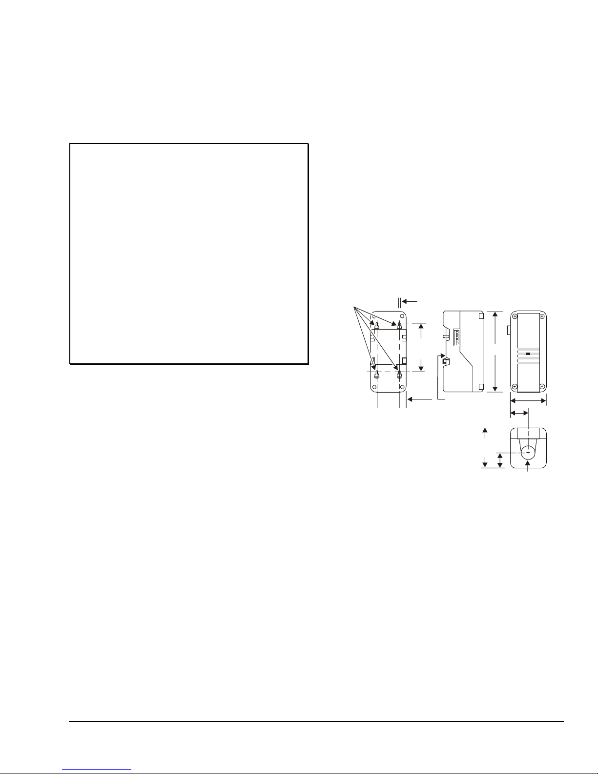
imensions
D
Mounting Slots
For No. 6 Screws
1-1/2
(40)
1/8 (4)
2-15/16
(75)
7/16
(11)
DIN Rail
Mount
5 (127)
1-3/16
(31)
ON
JOHNSON
CONTROLS
CONTROLS
2-3/8
(61)
S350
O
O
Differential Adjustment
Differential is defined as the difference in degrees,
% RH, or psi between energization and
de-energization of the stage module’s relay.
Operation Mode Selection
The S350A, S351A, and S352A utilize jumpers (at
jumper terminal J2) to select the operation mode. (See
Adjustments
With the jumpers positioned horizontally, the stage
module is set for Cooling (S350A), Dehumidification
(S351A), or Direct Acting (DA) (S352A) operation. In
this mode the relay and LED indicator de-energize
when the sensed temperature, humidity, or pressure
drops to the setpoint
section and Figures 3, 4, and 5.)
plus
offset value.
2-3/8
(61)
7/8 (22)
Conduit
Hole
7/8 (22)
Figure 2: System 350 Stage Module
Dimensions, in. (mm)
ounting
M
Each System 350 Stage Module is housed in a
compact NEMA 1 plastic enclosure designed for
standard 35 mm DIN rail mounting. Four key-slot
mounting holes on the back of the control case are
provided for surface mounting. (See Figure 2.) The
modules are not position sensitive, but should be
mounted for convenient access to wiring and
adjustments.
Note: When mounting any System 350 module to
rigid conduit, attach the hub to the conduit
before securing the hub to the control
enclosure.
S350A Temperature, S351A Humidity, and S352A Pressure Stage Modules Product/Technical Bulletin
3
Page 4

djustments
A
Refer to the following steps for adjusting stage module
settings. (See Figures 3, 4, and 5.)
!
WARNING:
Risk of Electrical Shock.
Disconnect power supply to
avoid possible electrical shock or
equipment damage. More than
one disconnect may be required
to completely de-energize
equipment.
1. Ensure all power to system is off.
Each stage module may be receiving separate
power sources. Make sure all power sources to
each stage module are off.
2. Remove the stage module cover by loosening the
four captive cover screws.
Set the mode of operation
3.
by positioning the
jumpers (at jumper terminal J2) for Cooling,
Dehumidification, or Direct Acting mode. Position
the jumpers vertically for Heating, Humidification,
or Reverse Acting mode.
Note: The S350A, S351A, and S352A Stage
Modules are configured with the jumpers in
the horizontal position at the factory.
Adjust the differential
4.
using the potentiometer
marked DIFF to the desired setting (the difference
in degrees, % RH, or psi between energization
and de-energization of the stage module’s relay).
Adjust the offset
5.
using the potentiometer marked
OFFSET to the number of degrees, % RH, or psi
from the System 350 control’s setpoint at which
the stage relay de-energizes (above setpoint with
Cooling, Dehumidification, or Direct Acting mode
selected, or below setpoint with Heating,
Humidification, or Reverse Acting mode selected).
6. Replace the cover on the stage module and fasten
in place with screws.
7. Restore power to system.
Potentiometer
Module
Connector
Relay Energized
LED Indicator
Cover Screw
1 of 4
Offset
N.C.
Relay
Relay
COM
Output
Differential
Potentiometer
Module
Connector
Jumper
Position at J2
Heating
Cooling
N.O.
Terminals
Figure 3: Interior View of S350A Stage Module
Offset
Potentiometer
Module
Connector
Relay Energized
LED Indicator
Cover Screw
1 of 4
N.C.
Relay
Relay
COM
Output
Differential
Potentiometer
Module
Connector
Jumper
Position at J2
Humidification
Dehumidification
N.O.
Terminals
Figure 4: Interior View of S351A Stage Module
Offset
Potentiometer
Module
Connector
Relay Energized
LED Indicator
Cover Screw
1 of 4
Relay
Differential
Potentiometer
Module
Connector
Jumper
Position at J2
Reverse
Acting
Direct
Acting
4
S350A Temperature, S351A Humidity, and S352A Pressure Stage Modules Product/Technical Bulletin
N.C.
Relay
COM
Output
N.O.
Terminals
Figure 5: Interior View of S352A Stage Module
Page 5

Higher
Temperature
Setpoi nt
Temperature
Lower
Temperature
ON
Differential
ON
Differential
OFF
OFFSET
OFF
OFF
ON = Energized
OFF = De-energized
A350
Stage 1
S350A
Stage 2
Cooling
OFFSET
Differential
S350A
Stage 3
ON
OFFSET
OFF
Differential
S350A
Stage 4
Heating
ON
S350A
Stage 5
OFFSET
OFF
Differential
ON
Higher
Pressure
Setpoint
Pressure
Lower
Pressure
Differential
ON
Differential
OFF
OFFSET
OFF
ON = Energized
OFF = De-energized
P352AB
Stage 1
S352A
Stage 2
Direct
ON
OFFSET
OFF
S352A
Stage 3
Reverse
Differential
ON
S352A
Stage 4
OFFSET
OFF
Differential
ON
Figure 6: Example of a Heating/Cooling
Application Using One A350 and Four S350As
Higher
Humidity
Setpoi nt
Relative
Humidity
Lower
Humidity
ON
Differential
OFF
ON = Energized
OFF = De-energized
W351
Stage 1
Dehumidify
OFF
OFFSET
S351
Stage 2
ON
Differential
OFFSET
OFF
S351
Stage 3
Humidify
Differential
ON
OFFSET
OFF
S351
Stage 4
Differential
ON
Figure 7: Example of a
Humidification/Dehumidification Application
Using One W351 and Three S351As
Figure 8: Example of a Reverse Acting/Direct
Acting Application Using One P352AB
and Three S352As
iring
W
Refer to the following guidelines and wiring diagrams
for proper wiring and terminal designations (See
Figures 9, 10, and 11.)
Note: For information on connecting to an external
transformer refer to the applicable control
bulletin.
!
WARNING:
Risk of Electrical Shock.
Disconnect power to avoid
possible electrical shock or
equipment damage. More than
one disconnect may be required
to completely de-energize
equipment.
IMPORTANT: Make all wiring connections in
accordance with the National
Electrical Code and all local
regulations. Use copper
conductors only. Do not exceed
the control’s electrical ratings.
S350A Temperature, S351A Humidity, and S352A Pressure Stage Modules Product/Technical Bulletin
The stage modules plug into the control and other
add-on modules via 5-pin connectors located on either
side of each module. Wiring is made at the Normally
Open (N.O.)/Normally Closed (N.C.) relay terminal
strip. (See Figures 3, 4, and 5.)
5
Page 6

Wire
Ter min al
Block
24V
COM
VDC
SEN
120 VAC
SEN
Shield (Connect
only to COM on A350)
A350
COM
Y350R
Sensor
Isolate and tape. (Do not ground
this end of cable shield.)
S350A D350
S350A S350A
Load
Load
Load
Load
Figure 9: Typical Multistage Temperature Control System Using 120 VAC Power Supply
Transmitter
Wire
Ter min al
Block
24V
COM
VDC
SEN
120 VAC
SEN
only to COM on W351)
W351 Y350R
VDC
Shield (Connect
Load Load
COM
S351A D351S351A S351A
Isolate and tape. (Do not ground
this end of cable shield.)
Load
Load
Figure 10: Typical Multistage Humidity Control System Using 120 VAC Power Supply
SEN
only to COM on P352AB)
P352AB
VDC
Shield (Connect
Y350R S352A S352A
COM
Wiring Harness
Isolat e and tape. (Do not ground
this end of cable shield.)
P399 Transducer
D352AS352A
Wire
Ter min al
Block
24V
COM
VDC
SEN
120 VAC
Figure 11: Typical Multistage Pressure Control System Using 120 VAC Power Supply
6
S350A Temperature, S351A Humidity, and S352A Pressure Stage Modules Product/Technical Bulletin
Load
Load
Load
Load
Page 7

heckout Procedure
C
Before applying power, make sure installation and
wiring connections are according to job specifications.
After necessary adjustments and electrical
connections have been made, put the system in
operation and observe at least three complete
operating cycles before leaving the installation.
roubleshooting
T
If the control system does not function properly, first
verify that the control, power, and display modules are
all operating correctly (refer to the respective
literature). Then inspect the stage modules for proper
operation.
Check that the proper operating mode
(Cooling/Heating, Dehumidification/Humidification, or
Direct Acting/Reverse Acting) has been selected on
each stage module. (See
Adjustments
section and
Figures 3, 4, and 5.) Then perform the following
procedures to determine the problem.
1. Verify the system has power.
2. Note the offset and differential settings on the
stage module.
3. Turn the setpoint dial on the control module to
minimum.
4. Increase the setpoint by slowly adjusting the
setpoint dial until the stage relay LEDs turn On
and Off as shown in Tables 3, 4, or 5.
Table 3: S350A Relay Troubleshooting
Operation
LED
Mode
Cooling
Cooling
Heating
Heating
*(Ts) = sensed temperature
On Closed
Off Open (Ts) – offset
On Closed
Off Open (Ts) + offset
N.O.
Relay
Status
Setpoint Dial
Setting
(Ts)* - offset
-
differential
(Ts) + offset
+
differential
Table 4: S351A Relay Troubleshooting
Operation
Mode
LED N.O.
Relay
Status
Dehumidify
Dehumidify
Humidify
Humidify
*(RHT) = actual relative humidity at transducer
On Closed (RHT)* -offset
Off Open (RH
On Closed (RH
Off Open (RHT) + offset
Setpoint Dial
Setting
-
differential
) - offset
T
) + offset
T
+
differential
Table 5: S352A Relay Troubleshooting
Operation
Mode
LED N.O.
Relay
Status
Direct
Direct
Reverse
Reverse
*(psiT) = actual pressure at transducer
On Closed (psiT)*- offset
Off Open (psi
On Closed (psi
Off Open (psiT) + offset
5. If the relays do not perform as indicated in
Tables 3, 4, or 5, adjust the stage module’s
differential and offset potentiometers to minimum
and repeat Steps 1 through 3.
6. If the relays still do not turn on and off, replace the
defective stage modules.
Note: There is the unlikely possibility that a defect in
one stage module could cause defective
symptoms in all modules. Plug each stage into
the control individually and check the
performance of each as explained above.
epairs and Replacement
R
Do not make field repairs or perform calibration.
Sensors and replacement controls are available
through your local Johnson Controls representative.
Setpoint Dial
Setting
differential
) - offset
T
) + offset
T
differential
-
+
S350A Temperature, S351A Humidity, and S352A Pressure Stage Modules Product/Technical Bulletin
7
Page 8

rdering Information
O
Table 6: Ordering Information
Item Product Code
Description
Number
S350A Temperature Stage
Module
S351A Humidity Stage Module
S352A Pressure Stage Module
pecifications
S
Product
Input Voltage
Power Consumption
Output Relay Electrical
Ratings
Differential Adjustment
Range
Offset Range
Ambient Temperature
Ambient Humidity
Material
Mounting
Agency Listing
The performance specifications are nominal and conform to acceptable industry standards. For application at conditions beyond these
specifications, consult Johnson Controls/Penn Application Engineering at (414) 274-5535. Johnson Controls, Inc. shall not be liable for
damages resulting from misapplication or misuse of its products.
S350AA-1C Temperature Stage Module with Fahrenheit Scale
S350AB-1C Temperature Stage Module with Celsius Scale
S351AA-1C Humidity Stage Module with percent RH Scale
S352AA-2C Pressure Stage Module with psi Scale
S350AA: Temperature Stage Module with Fahrenheit Scale
S350AB: Temperature Stage Module with Celsius Scale
S351AA: Humidity Stage Module with Percent RH Scale
S352AA-2: Pressure Stage Module with psi Scale
S350AA: Provided by the A350
S351AB: Provided by the W351
S352AA-2: Provided by the P352AB
1.0 VA maximun
SPDT Enclosed Relays
10 Ampere Non-inductive, 125 VA Pilot Duty, 24/240 VAC
1/2 hp 120/240 VAC
S350AA: 1 to 30F°
S350AB: 0.5 to 17C°
S351AA: 2 to 10% RH
S352AA-2: 2 to 50 psi
S350AA: 1 to 30F°
S350AB: 0.6 to 16.7C°
S351AA: 2 to 30% RH
S352AA-2: 2 to 50 psi
Operating: -30 to 150°F (-34 to 66°C)
Shipping: -40 to 185°F (-40 to 85°C)
0 to 95% RH (Non-condensing)
Case, Cover: NEMA 1 High Impact Thermoplastic
Wall or DIN Rail
UL Listed, CCN XAPX, File E27734
UL Listed for Canada, CCN XAPX7, File E27734
Controls Group
507 E. Michigan Street
P.O. Box 423 Printed in U.S.A.
Milwaukee, WI 53201 www.johnsoncontrols.com
8
S350A Temperature, S351A Humidity, and S352A Pressure Stage Modules Product/Technical Bulletin
 Loading...