

Page 1
Installation Instructions
Issue Date September 30, 2009
P66 Series Electronic Fan Speed Controls
Application
IMPORTANT: Use this P66 Series Electronic Fan
Speed Control only as an operating control. Where
failure or malfunction of the P66 control could lead to
personal injury or property damage to the controlled
equipment or other property, additional precautions
must be designed into the control system.
Incorporate and maintain other devices, such as
supervisory or alarm systems or safety or limit
controls, intended to warn of or protect against
failure or malfunction of the P66 control.
The P66 Series Electronic Fan Speed Controls are
pressure-actuated electronic motor-speed controllers
designed primarily to control condenser fan motors on
Heating, Ventilating, Air Conditioning, and
Refrigeration (HVAC/R) applications (Figure 1). These
controls vary the supply voltage to the fan motor in
response to the sensed refrigerant pressure, providing
direct response to changes in condenser pressure,
regardless of the variations in air delivery curves.
P66 controls are available with one or two pressure
sensor inputs. In dual sensor models, the control
selects the input with the greatest demand.
P66 control models are also available with NEMA 3R
(Rainproof) enclosures for outdoor applications
(Figure 1). These models come with a plastic
enclosure, appropriate gaskets, and low voltage wire
leads for 24 VAC power. In addition, the critical high
voltage components are encapsulated in a potting
compound.
Note: NEMA 1 models cannot be retrofitted in the
field to obtain the NEMA 3R (Rainproof) rating.
A P66 and speed controlled motor can replace On/Off
fan cycling controls, multiple speed motors, condenser
flood-back systems, temperature fan-speed controls,
and modulating louver systems.
Typical applications include:
• computer roo m air conditioning
• commercial a i r conditioning
• commercial refrigeration
The P66 Series controls must be applied only to
single-phase motors intended for use with a solid-state
motor speed control. An applicable motor must be a
single-phase, permanent split-capacitor motor and
must be:
• ball-bearing constructio n only (Sleeve-bearing
motors are not acceptable for use with P66
controls.)
• designe d to handle non-sinusoidal waveforms
generated by solid-state motor speed controls
• designe d to dissipate the motor heat generated at
reduced speed operation
!
CAUTION: Risk of Property Damage
Use only single-phase Permanent Split-Capacitor
(PSC) motors approved by the manufacturer for
speed control applications with the P66 control.
Failure to use a single-phase PSC motor may
damage the motor and other property.
Installation
!
WARNING: Risk of Personal Injury
Do not install the P66 Electronic Fan Speed Control
in any application using corrosive or flammable
refrigerants. The P66 control is not designed or
intended for use with those refrigerants. Use of the
P66 control with corrosive or flammable refrigerants
may lead to release of refrigerant, which could cause
property damage, fire, severe personal injury or
death.
© 2009 Johnson Controls, Inc. 1
Part No. 24-7664-1482, Rev. D
Page 2
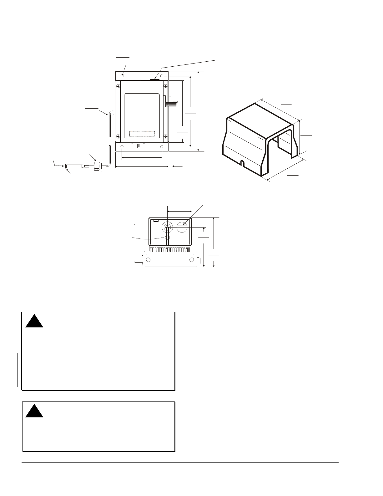
Dimensions
Depressor
Valve
1/4 in. Flare
0.093
2.36
Diameter
Capillary
7/16 in.
20 UNF-2B
0.218
Diameter Mounting Holes
5.54
for No. 10 Screw
3.38
86
4.56
116
5.26
0.27
7
1.28
33
134
6.00
152
6.75
172
0.875
22.23
Two 0.250 Spade Ter m in als
for 24 VAC Power Supply
Inside Plug (NEMA 1 Enclosure)
Diameter
Conduit Hole
(2 places)
NEMA 3R Enclosure
5.33
135
4.20
107
4.72
120
Two 22 AWG W ire
Leads for 24 VAC
Power Supply
(NEMA 3R
Enclosure)
Figure 1: P66 Control and NEMA 3R Enclosure Dimensions, in./mm
Mounting
Observe the following guidelines when mounting a
P66 control and routing the control’s capillary tube:
!
CAUTION: Risk of Environmental and
Property Damage
Coil and secure excess capillary tubing away from
contact with sharp or abrasive objects or surfaces.
Vibration or sharp or abrasive objects in contact with
capillary tubes can cause damage that may result in
refrigerant leaks or loss of element charge which
may result in damage to the environment or
property.
!
CAUTION: Risk of Environmental and
Property Damage
Avoid sharp bends in the capillary tubes. Sharp
bends can weaken or kink capillary tubes which may
result in refrigerant leaks or restrictions of flow.
3.34
85
4.12
105
P66_DIMS_ENCLOSURE
• Maintain operating pre s sures and temperatures
within the listed product ratings to assure reliable
operation. See Technical Specifications table.
• Mount the P66 control away from sources of
excessive heat.
• Mount the P66 control with the cooling fins in a
vertical position with no obstruction preventing
airflow through the fins.
• Locate the P66 control wh ere fan air passes
through the cooling fins to maximize heat
dissipation.
• Locate the P66 control so the pressure elements
inside the base are above the refrigerant liquid
level of the controlled equipment.
• Mount the control wh ere it can be conveniently
wired to the power supply and the motor.
• Provide the recommended pressure connection in
the high-pressure vapor line near the condenser
inlet. (A 60 in. capillary is standard.)
2 P66 Series Electronic Fan Speed Controls Installation Instructions
Page 3
• Evacuate all tubing and lines before connecting
the P66 control.
Note: A Schrader® valve depressor is provided with
the female flare fitting on standard P66 control models.
Wiring
!
WARNING: Risk of Electric Shock
Disconnect power supply before making electrical
connections. Contact with components carrying
hazardous voltage can cause electric shock and
may result in severe personal injury or death.
Correct
!
WARNING: Risk of Electric Shock
Ground the P66 Series Electronic Fan Speed
Control according to local, national, and regional
regulations. Failure to ground the P66 control may
result in electric shock and severe personal injury or
death.
IMPORTANT: Use copper conductors only. Make all
wiring connections in accordance with the National
Electrical Code and local regulations. Do not exceed
the P66 Series Electronic Fan Speed Control’s
electrical ratings.
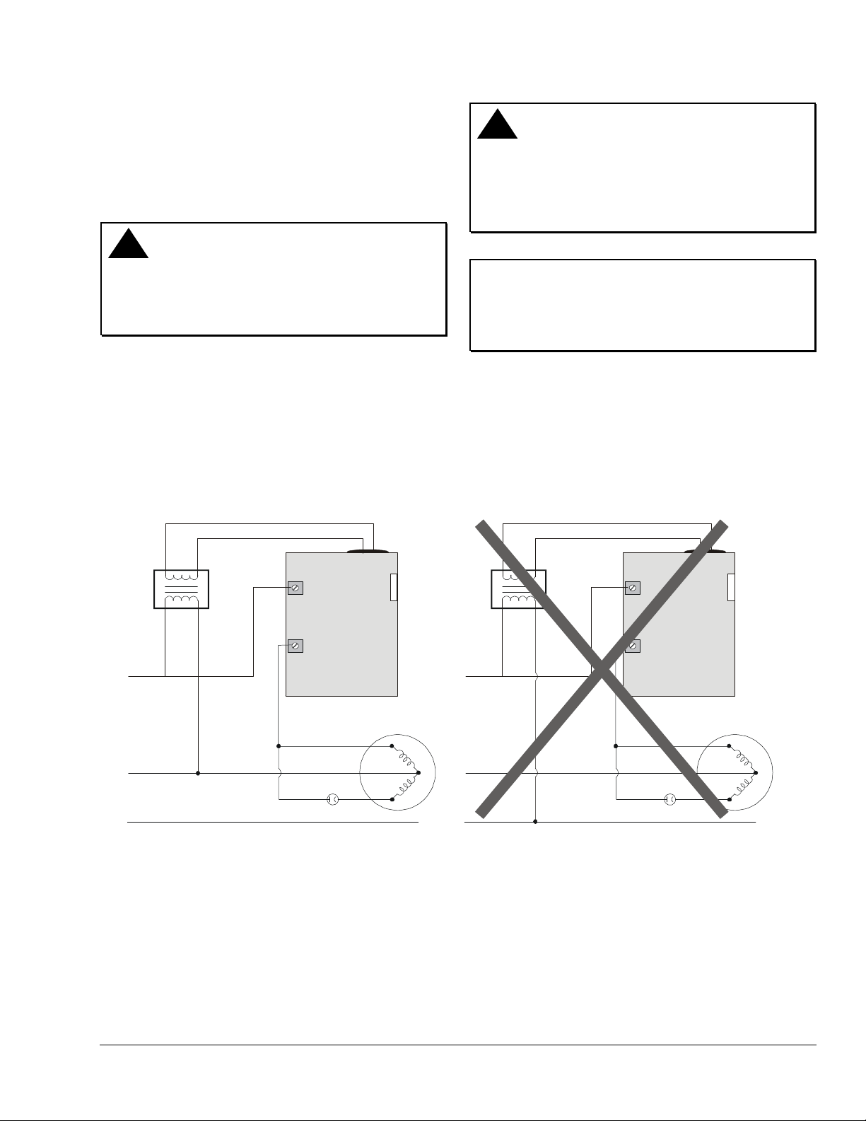
The P66 control must be supplied with 24 VAC (1 VA)
from an external transformer powered from the same
phase as the motor circuit (Figure 2, Figure 3, and
Figure 4). The low voltage input connections are 1/4
in. quick-connect terminals on the NEMA 1 models
and two 6 in. 22 AWG wires on the NEMA 3R models.
The line voltage connections are 10-32 screw
terminals.
Incorrect
L1
L2
L3
24
VAC
L1
M1
Capacitor
P66
Main
Aux
Motor
R
S
L1
C
L2
L3
24
VAC
L1
M1
Capacitor
Figure 2: Permanent Split-Capacitor Motor Connections to the P66 Fan Speed Control
(The 24 VAC power supply must be connected in-phase with the motor power supply.)
P66
Main
Aux
Motor
R
C
S
P66_IN-PHASE_WIRRING
P66 Series Electronic Fan Speed Controls Installation Instructions 3
Page 4
24
VAC
L1
M1
L1
L2
Capacitor
P66
Main
Aux
Motor
R
S
C
P66_WIRING
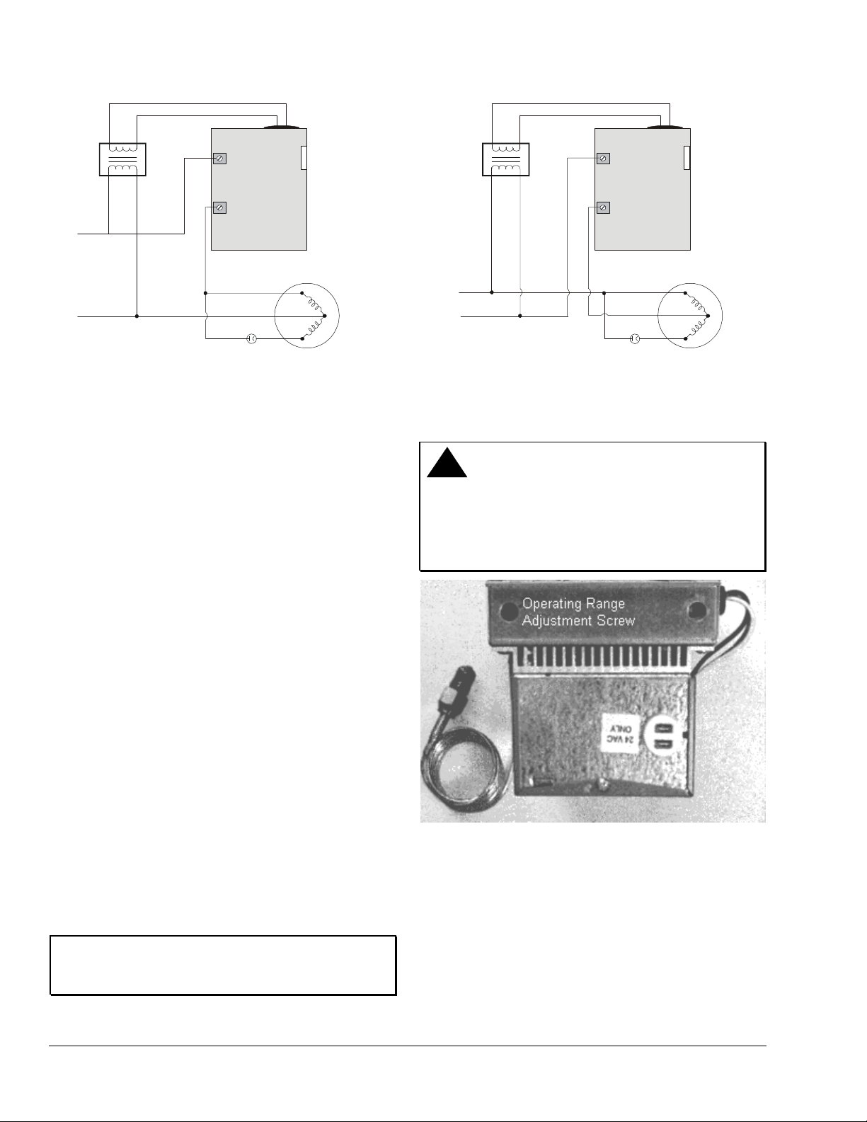
Figure 3: Permanent Split-Capacitor Motor
Connections to the P66 Fan Speed Control
Setup and Adjustments
The P66 control’s throttling range is fixed and cannot
be adjusted. The operating range pressure is
adjustable within the control pressure range. See the
Technical Specifications table for P66 model pressure
ratings.
To adjust the operating range pressure:
1. Apply a reliable pressure gauge to the controlled
system to monitor the pressure adjustments.
24
VAC
L1
M1
P66
Motor
L1
L2
Capacitor
Main
Aux
R
C
S
P66_WIRING_OPT
Figure 4: Optional Wiring Diagram for Permanent
Split-Capacitor Motor Connections to the P66
Fan Speed Control
!
CAUTION: Risk of Property Damage
Limit any adjustments to two full turns in either
direction. Over-adjustment may prohibit modulation
of the motor resulting in high head pressures. All
pressure adjustments should be verified with the use
of refrigerant pressure gauges.
2. Access the operating range adjustment screw for
the P66 pressure transducer through the opening
in the upper left-hand corner of the P66 control
base (Figure 5).
Note: On dual pressure models, access to the
second adjustment screw is located in the lower righthand corner of the control base.
3. Turn the adjustment screw 1/2 turn (or less)
clockwise to increase the operating range
pressure or 1/2 turn (or less) counterclockwise to
decrease the operating range pressure.
• Low Pressure Models (80 to 200 psig):
1/2 turn = approximately ± 9 psig (62 kPa)
• Medium Pressure Models (140 to 350 psig):
1/2 turn = approximately ± 18 psig (124 kPa)
• High Pressure Models (300 to 500 psig):
1/2 turn = approximately ± 35 psig (241 kPa)
IMPORTANT: Do not adjust the operating range
screw more than 1/2 turn before allowing the system
pressure to stabilize.
4. Check system pressure and repeat Step 3 until
the desired operating range pressure is attained.
Figure 5: Operating Range Adjustment Screw
Location
Checkout
Before leaving the installation, observe working
application for correct operation. See the Operation
section for a typical operational sequence.
4 P66 Series Electronic Fan Speed Controls Installation Instructions
Page 5
Operation
Condensing unit installation, operation, and
maintenance determine the overall capability of
maintaining a satisfactory pressure by means of fan
speed control. Within the operating range, the P66
control provides air delivery in direct proportion to heat
rejection requirements. This allows the refrigeration
system to perform efficiently in very low ambient
temperatures.
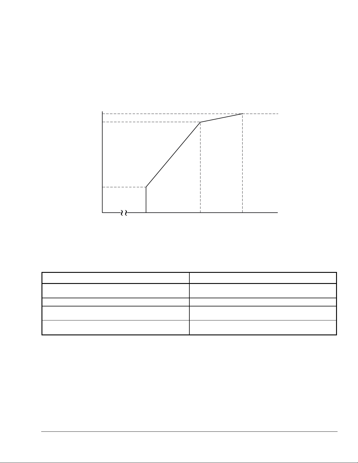
97%
90%
Motor Voltage
10% to 40%
of Line
(model sp ecific)
No fan operation
in this
pressure range.
0
psig
Operating Range
(190/250 psig)
The P66 pressure transducer provides direct response
to changes in condenser pressure, regardless of the
variations in fan delivery curves. The dual input
models select the pressure input from the transducer
sensing the highest pressure.
See Figure 6 for a typical operational sequence for a
P66 control.
Operating Range
Plus 20 or 30 psi*
Pressure In pu t
350 psig
*20 psi for 30 psi Effective Throttling Range (ETR)
30 psi for 60 psi Effective Throttling Range (ETR)
Figure 6: Operation Chart for the P66 Fan Speed Control
Table 1: P66 Control Operation
Pressure Input Motor Voltage (VAC, true RMS)
Pressure is between 0 psig and the low end of the
operating range.
Pressure is at the low end of the operating range.
Pressure is in the operating range.
Pressure is above the operating range.
0 to 5 volts
Start voltage (10% to 40% of line - model specific)
Motor voltage varies directly with system pressure from start
voltage to 90% of line voltage.
A further pressure increase of 20 to 30 psi will increase
motor voltage to 97% of the applied voltage.
P66_OP_CHART
P66 Series Electronic Fan Speed Controls Installation Instructions 5
Page 6
Troubleshooting
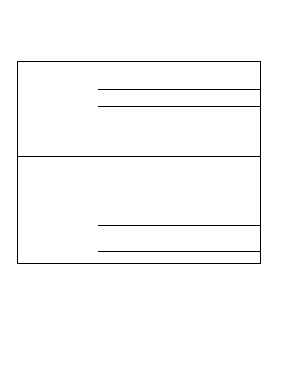
Refer to the Operation section for proper operation.
Table 2: Troubleshooting Chart
Problem Possible Cause Possible Solution
No Fan Operation
Fan stops when pressure reaches
the high end of the operating range.
No Fan Modulation (On-Off
Operation)
Fan Starts at Full Speed.
Erratic Fan Operation
Fan motor is cycling thermal
overload.
Input pressure is below operating
range.
No 24 volt control voltage Check for 24 VAC at control.
No input pressure to control Alignment. Schrader valve depressor
Bad fan motor Disconnect power. Place a jumper from L1
Pressure transducer problem See Pressure Transducer
Control is not wired correctly. See wiring diagrams. Ensure that the
Control is not wired correctly. See wiring diagrams. Ensure that the
Pressure transducer problem See Pressure Transducer
Control is not wired correctly. See wiring diagrams. Ensure that the
Pressure transducer problem See Pressure Transducer
Control is not wired correctly. Check to see if control voltage (24 VAC) is
Dirty or blocked condenser coil Clean condenser coil.
Pressure transducer problem See Pressure Transducer
Dirty or blocked condenser coil Clean condenser coil.
Wrong motor for fan speed control
application
No problem, normal operation.
must depress Schrader valve enough to
allow pressure into capillary.
and connect power. If fan does not
to M
1
start, motor is bad and should be
replaced.
Troubleshooting section.
24 VAC power supply is connected
in-phase with the motor power supply.
24 VAC power supply is connected
in-phase with the motor power supply.
Troubleshooting.
24 VAC power supply is connected
in-phase with the motor power supply.
Troubleshooting.
on same phase as motor.
Troubleshooting.
Replace with motor approved for fan
speed control application.
Pressure Transducer Troubleshooting
1. Disconnect 6-pin connector from right side of
control.
Repairs and Replacement
Field repairs must not be made. For a replacement
control, contact the Original Equipment Manufacturer
or your local Johnson Controls/PENN distributor.
2. Place a jumper wire between third pin from the
top and the bottom pin on the control, not the
cable.
a. If fan goes to full speed, check for input
pressure.
b. If there is adequate pressure, the transducer
is bad and the control must be replaced.
6 P66 Series Electronic Fan Speed Controls Installation Instructions
Page 7
Ordering Information
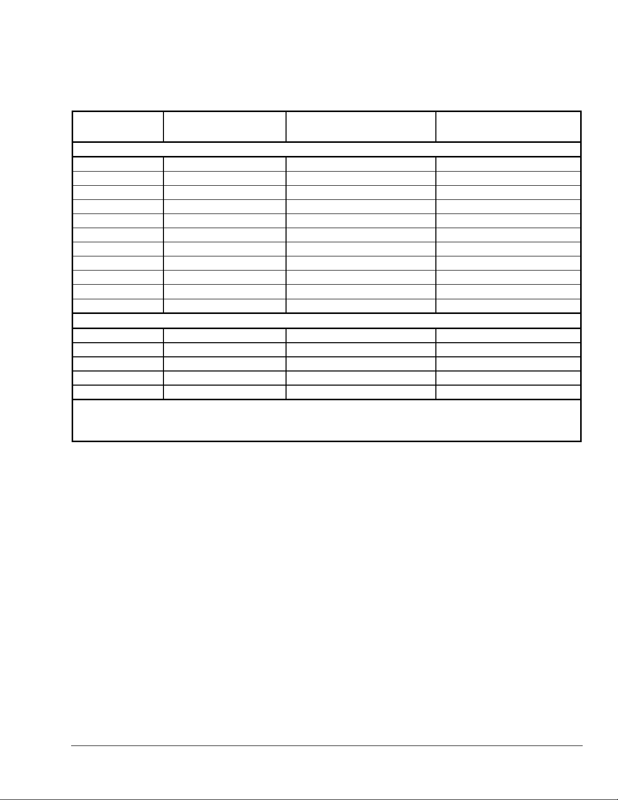
Table 3: P66 Control Specific Model Information
Product Code
Number
P66AAB-1
P66AAB-4
P66AAB-6
P66AAB-9
P66AAB-10
P66AAB-11
P66AAB-14
P66AAB-15
P66AAD-1*
P66ABB-21+
P66AAB-34
P66BAB-1
P66BAB-3
P66BAB-4
P66BAB-5
P66BAD-1*
All models are rated for 208-240/277/480 volt; 60Hz except those with Product Code Numbers followed by an asterisk.
* 50 Hz Models
+
Models with NEMA 3R Enclosure
Operating Range
(psig)
Single Input Sensor Models
190/250 10 60
135/165 10 60
170/230 16 60
170/230 40 60
190/250 16 120
140/200 16 60
220/280 40 120
190/250 40 60
160/220 25 60
220/280 16 120
320/410 40 60
Dual Input Sensor Models
190/250 10 60
170/230 16 60
190/250 16 120
190/250 40 60
160/220 25 60
Start Voltage
(% of Supply Voltage)
Capillary Length (in.)
For further information on model specifications and options, please contact Johnson Control s Application
Engineering at 1-800-275-5676.
P66 Series Electronic Fan Speed Controls Installation Instructions 7
Page 8
Technical Specifications
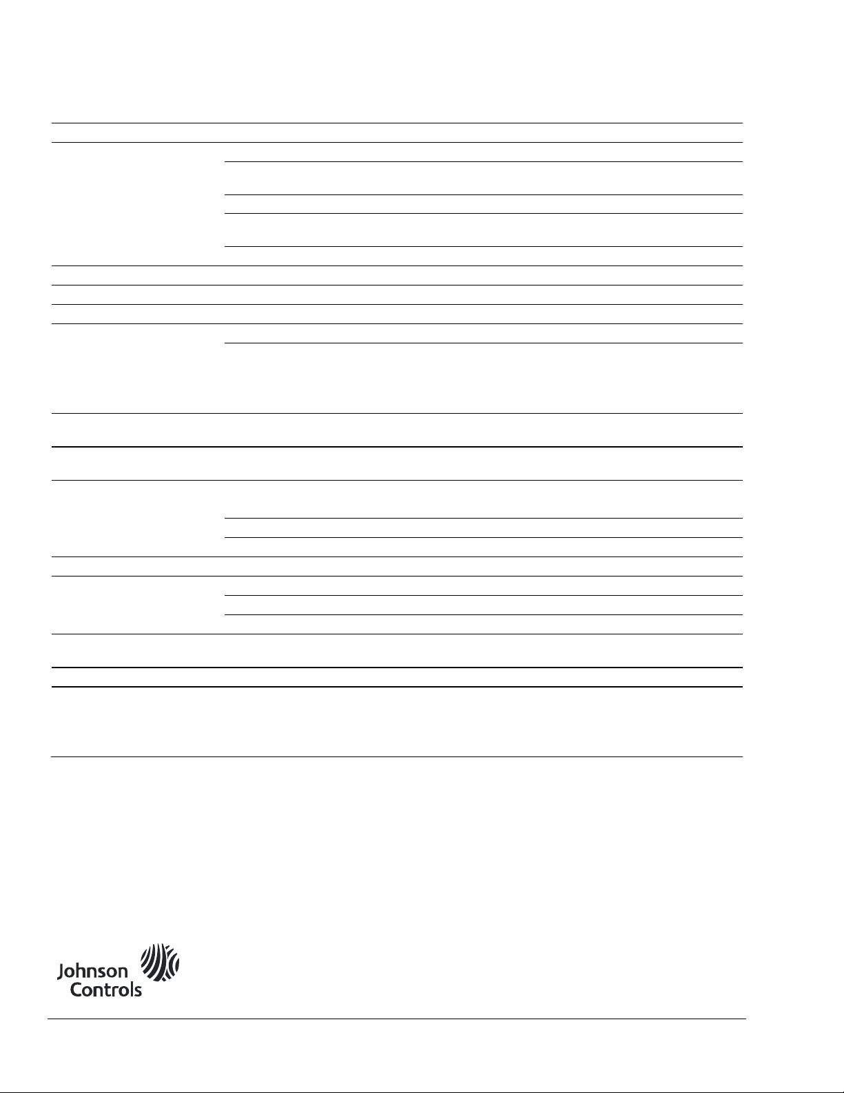
Product
Pressure Ratings Low Pressure Models Medium Pressure Models High Pressure Models
Control Range
Effective Throttling Range
Maximum Working
Pressure
Maximum Overpressure
Control Voltage
Line Voltage Range
Start Voltage
Electrical Ratings 208 VAC 240 VAC 277 VAC 480 VAC
Full Load Amperes
Locked Rotor Amperes
Ambient Temperature
Maximum
Ambient Temperature
Minimum
Ambient Storage
Temperature
Construction
Control Case
Base and Sensors
Plastic Enclosure
Enclosure
Wiring Connections
Low Voltage
Line Voltage
Pressure Connections
Mounting
Agency Listings
The performance specifications are nominal and conform to acceptable industry standards. For application at conditions beyond these
specifications, contact Johnson Controls Application Engineering at 1-800-275-5676. Johnson Controls, Inc. shall not be liable for damages
resulting from misapplication or misuse of its products.
P66 Series Electronic Fan Speed Controls
80 to 200 psig
(552 to 1379 kPa)
30 psi (207 kPa) 60 psi (414 kPa) 90 psi (621 kPa)
200 psig (1379 kPa) 350 psig (2413 kPa) 500 psig (3447 kPa)
250 psig (1724 kPa) 400 psig (2758 kPa) 695 psig (4792 kPa)
24 VAC, 1VA
208 to 480 VAC
10% to 40% of line (OEM specified - model specific)
8.0 8.0 6.9 4.0
16.5 16.5 14.3 10.5
130°F/54°C 130°F/54°C 130°F/54°C 150°F/66°C
-40°F/-40°C (at all Voltages)
-40°F/-40°C to 185°F/85°C
Galvanized steel case and cover
Galvanized steel
UV stabilized polycarbonate with closed cell foam gasket (NEMA 3R models only)
NEMA 1 or NEMA 3R (Rainproof)
1/4 in. quick connects (NEMA 1); Two 6 in. 22 AWG Wire Leads (NEMA 3R)
10-32 Screw Terminals
60 in./1524 mm or 120 in./3048 mm copper capillary with 1/4 in./6 mm flare nut and
Schrader valve depressor
Vertical only; two holes for No. 10 screws at the top and bottom
UL Recognized (U.S.): File SA516, Guide SDFY2
UL Recognized (Canada): File SA516, Guide SDFY8
CSA Certified: File LR 948, Class 1222 01 - Specific models only. Contact Johnson
Controls Application Engineering at 1-800-275-5676 for specific model information.
140 to 350 psig
(965 to 2413 kPa)
300 to 500 psig
(2048 to 3447 kPa)
Metasys® and Johnson Controls® are registered trademarks of Johnson Controls, Inc.
All other marks herein are the marks of their respective owners. © 2009 Johnson Controls , Inc.
8 P66 Series Electronic Fan Speed Controls Installation Instructions
Building Efficiency
507 E. Michigan Street, Milwaukee, WI 53202
 Loading...