

Page 1
!
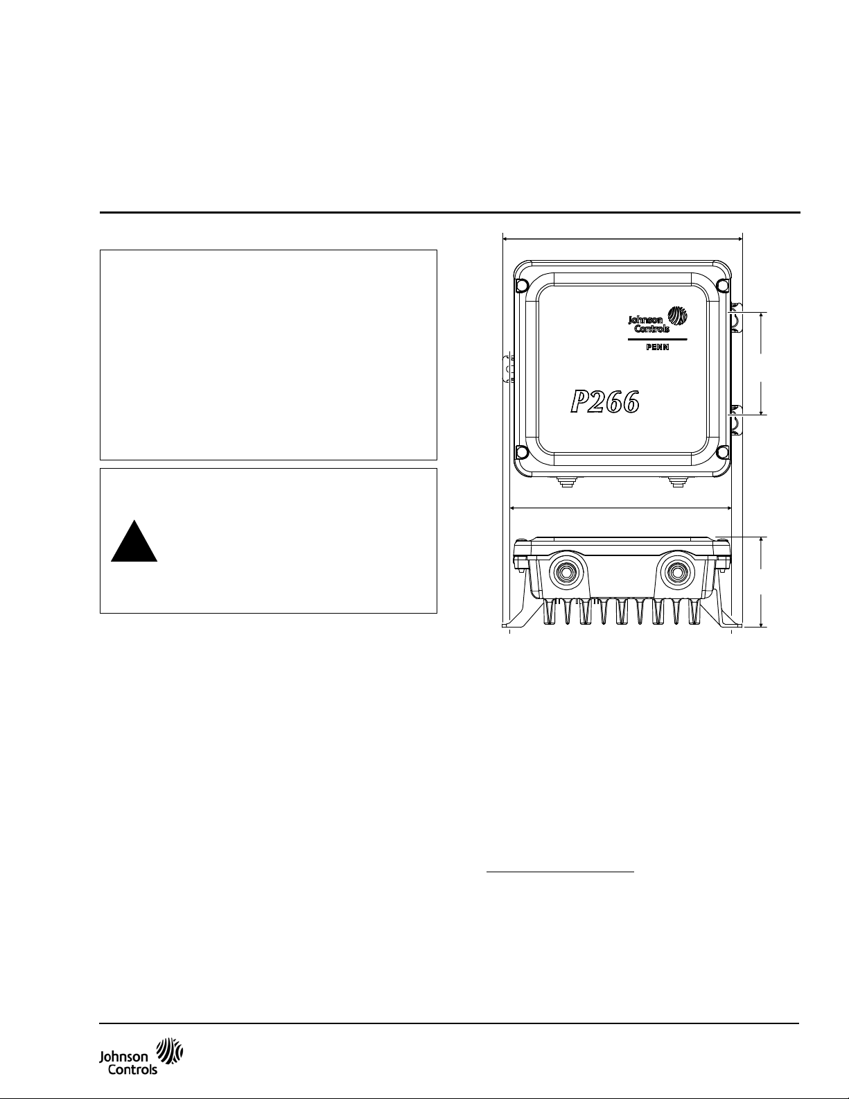
Figure 1: P266 Single-Phase Condenser
Fan Speed Control Mounting Dimensions, mm (in.)
165
(6-1/2)
(7)
P266 Series Single-Phase Condenser Fan Speed Control
Installation Instructions
P266xxx-x
Refer to the QuickLIT Web site for the most up-to-date version of this document.
Part No. 24-7664-2705, Rev. E
Issued September 3, 2010
Supersedes August 27, 2010
Application
IMPORTANT: Use this P266 Series Single-Phase
Condenser Fan Speed Control only as an operating
control. Where failure or malfunction of the P266
Series Fan Speed Control could lead to personal
injury or property damage to the controlled
equipment or other property, additional precautions
must be designed into the control system.
Incorporate and maintain other devices, such as
supervisory or alarm systems or safety or limit
controls, intended to warn of or protect against
failure or malfunction of the P266 Series Fan Speed
Control.
CAUTION: Risk of Property Damage
Use only single-phase Permanent S plit
Capacitor (PSC) motors approved by the
manufacturer for speed control
application with the P266 Series control.
Failure to use a single-phase PSC motor
may damage the motor and other
property.
The P266 Series Single-Phase Condenser Fan Speed
Control is a cost-effective, compact, weather-resistant,
and durable speed control for single-phase PSC
motors used in a wide variety of low-ambient
refrigeration and air conditioning condenser
applications.
The P266 Series Fan Speed Controls are designed to
replace the Johnson Controls® P66 Series and P215
Series Fan Speed Controls and provide additional
features and application flexibility.
Mounting
Location Considerations
Observe these guidelines when locating and mounting
a P266 Series Fan Speed Control:
• Ensure that the mounting surface and mounting
hardware can support the control and wiring.
178
FIG:p266_dims
76
(3)
66
(2-5/8)
• Mount the P266 Series control upright on a vertical
surface with the heat sink fins oriented vertically
and the conduit/electrical holes facing down.
• Ensure that air can flow through the heat sink fins
and provide 10 cm (4 in.) minimum clearance
around the heat sink.
• Mount the P266 Series control in a location away
from sources of excessive heat and within the
specified ambient operating conditions. See
Technical Specifications
conditions.
for ambient operating
P266 Series Single-Phase Condenser Fan Speed Control Installation Instructions 1
Page 2
Wiring
!
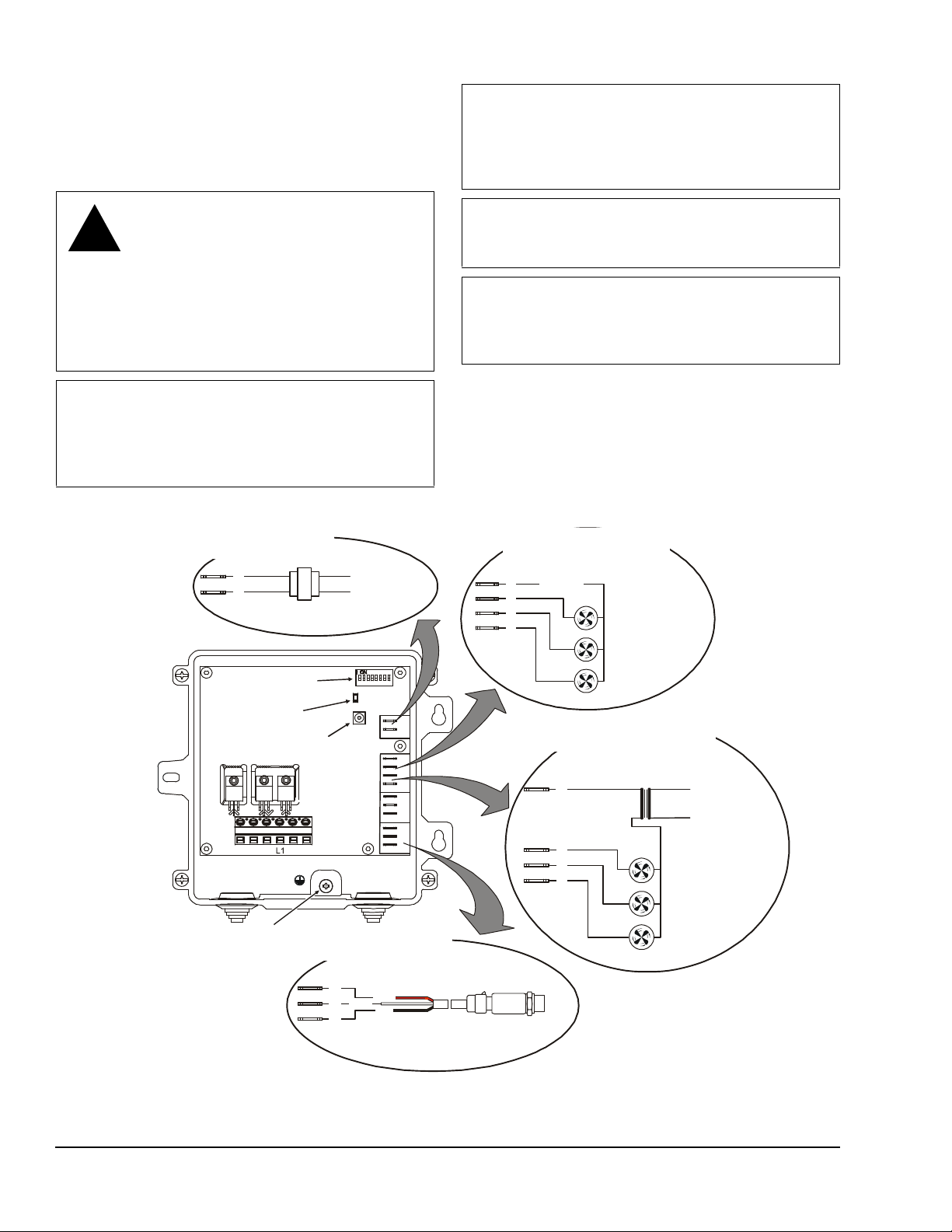
Figure 2: P266 Series Control Physical Features and Low-Voltage Wiring
24 VAC Class 2 Supply Po wer Wiring
for , , and Type Cont r ols
P266A P266B P266C
24 VAC Class 2
Power Supply
120/240 VAC
Primary Supply
Power
A
C
(Optional)
(Optional)
(Optional)
A
for , , and Type Contro ls
P266A P266B P266C
24 VAC
V
P
C
P1
wire the P2 terminals the same
as P1 term in als.
Pressure Transduce r Cl ass 2
Wiring for Models
All P266
Wht
Red
Blk
DIP Switch Block
Earth Ground
Connection
Push-Button
LED
M3
M2M1
L2/N L2/N
A
C
A
1
2
3
F
V
P
C
V
P
C
P2
P1
Primary Supply
Power
(Optional)
(Optional)
(Optional)
Class 2 Powe r
Wiring for Type Control s
P266 E
Power Supply
FIG:P266_lwV_wi rng
Refer to the model-specific wiring diagram located on
the interior label of the P266 Series control and
observe these guidelines when wiring the P266 Series
control:
IMPORTANT: Do not exceed the P266 Series Fan
Speed Control electrical rating s. Exceeding P266
Series control electrical ratings can result in
permanent damage to the P266 Series control and
void any warranty.
WARNING: Risk of Electric Shock.
Disconnect or isolate all power supplies
before making electrical connections.
More than one disconnect or isolation
may be required to completely
de-energize equipment. Contact with
components carrying hazardous voltage
can cause electric shock and may result
in severe personal injury or death.
IMPORTANT: Do not connect supply power to the
P266 Series control before finishing wiring and
checking all wiring connections. Short circuits or
improperly connected wires can result in damage to
the P266 Series control and vo id an y war ra nt y.
IMPORTANT: Use 60/75 C copper conductors only .
Make all wiring in accordance with local, national,
and regional regulations.
IMPORTANT: Electrostatic discharge can damage
P266 control components. Use proper Electrostatic
Discharge (ESD) precautions during installation and
servicing to avoid damaging P266 components.
• Ensure that the wires between the P266 Series
control and the fan motor do not exceed 15 m
(50 ft).
• Wires connected to the line-voltage terminal block
must be 3.31 mm
2
(12 AWG) or smaller.
• Low-voltage wires must be less than 30 m (100 ft).
24 VAC Class 2 Fan Control Wiri ng
1
2
3
F
Fan 1 Star t e r
Fan 2 Star t e r
Pressure Transduce r
If a second P266 transd ucer is used ,
Low-Volta ge ( <30 V) Cla ss 2 Auxi l iary Fan Control
C
Low-Voltage (<30V)
P266 Electronic
1
2
3
F
Fan 3 Star t e r
Exter nal Low- Volt age SELV
Line-Voltage VAC
Fan 1 Start er
Fan 2 Start er
Fan 3 Start er
P266 Series Single-Phase Condenser Fan Speed Control Installation Instructions2
Page 3
Low-Voltage Wiring
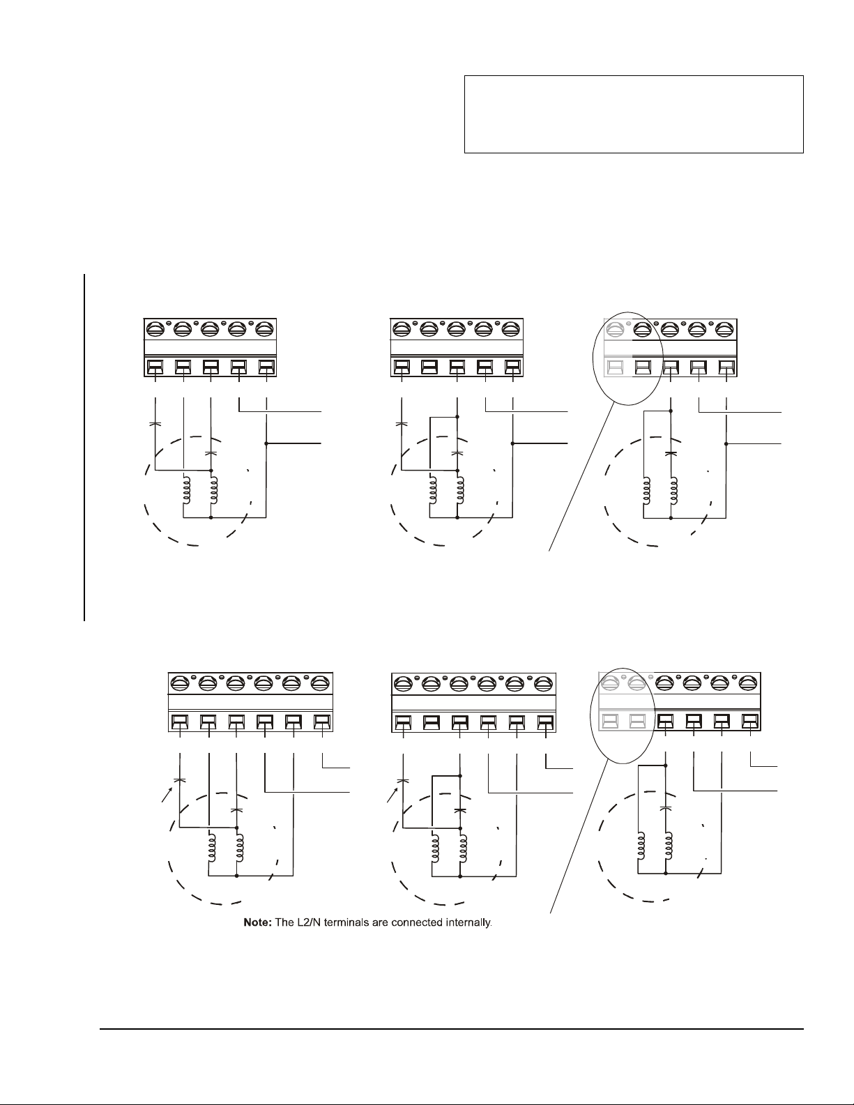
Figure 3: High-Voltage Wiring Options for P266A, P266B, and P266C Type Controls
M3
M2 M1
L1
L2/N
M3 M2 M1 L1 L2/N
Optional
Low-Speed
Capacitor
(LSC)
Auxilary
Capacitor
Auxiliary
Windings
Main
Windings
PSC
Motor
Line VAC
M3 M2 M1 L1 L2/N
Optional
Low-Speed
Capacitor
(LSC)
Auxilary
Capacitor
Auxiliary
Windings
Main
Windings
PSC
Motor
208/240 VA C
Main
Windings
PSC
Motor
Auxilary
Capacitor
Auxiliary
Windings
Line VAC
Note:
Some P266A, P2 6 6B
and P266C models d o not
have M2 or M3 Triacs.
Split Winding/Three Triac with LSC Wiring
for P266A Type Controls
(208/240 VAC Only)
Two Triac with LSC Wirin g fo r
P266A, P266B and P266C Type Controls
(208/240 V AC, 460/57 5 VA C )380/4 60 VAC, and
One Triac Wiring for
P266A, P266B, and P266C Type Controls
()
208/2 40 VA C , 380/460 V AC, and 460/575 VAC
A B
C
FIG:p266_NA_HiV_wirng
Figure 4: High-Voltage Wiring Options for P266E Type Controls
M2 or M3 Triacs.
M3
M2 M1
Windings
(208/240 VAC Only)
M3
M2 M1
L1 L2/N
L2/N
PSC
Motor
Main
Windings
Auxiliary
Windings
Auxilary
Capacitor
208/240 VA C
for P266E Type Controls
(208/240 VAC Only)
M3
M2 M1
L1 L2/N
L2/N
Main
Windings
Windings
Auxilary
208/240 VAC
for P266E Type Controls
(208/240 VAC Only)
Optional
Low-Speed
Capacitor
(LSC)
Optional
Low-Speed
Capacitor
(LSC)
A
B
C
Figure 2 shows the P266 Series control features under
the housing cover and the low-voltage wiring diagrams
for the P266A, P266B, P266C, and P266E T y pe control
models.
High-Voltage Wiring
Figure 3 shows the high-voltage wiring diagrams for
the P266A, P266B, and P266C Type control models.
Figure 4 show the high-voltage wiring diagrams for the
P266E Type control models.
IMPORTANT: The L2/N terminal must be
connected to line voltage in order for a P266 Series
control to comply with the FCC and IEC Class B
radio frequency interference emissions limit.
Use Table 1 to determine the high-voltage wiring
options available for P266A, P266B, P266C, and
P266E Type control models.
Split-Winding/Three Triac with LSC Wiring
Two Triac with LSC Wiring
Capacitor
Auxiliary
PSC
Motor
Single Triac Wiring
for P266E Type Controls
Main
Windings
Note:
Some P266E mode ls d o not have
L1 L2/N
Auxilary
Capacitor
Auxiliary
PSC
Motor
L2/N
208/240 VA C
FIG:p266_E_HiV_w irng
P266 Series Single-Phase Condenser Fan Speed Control Installation Instructions 3
Page 4
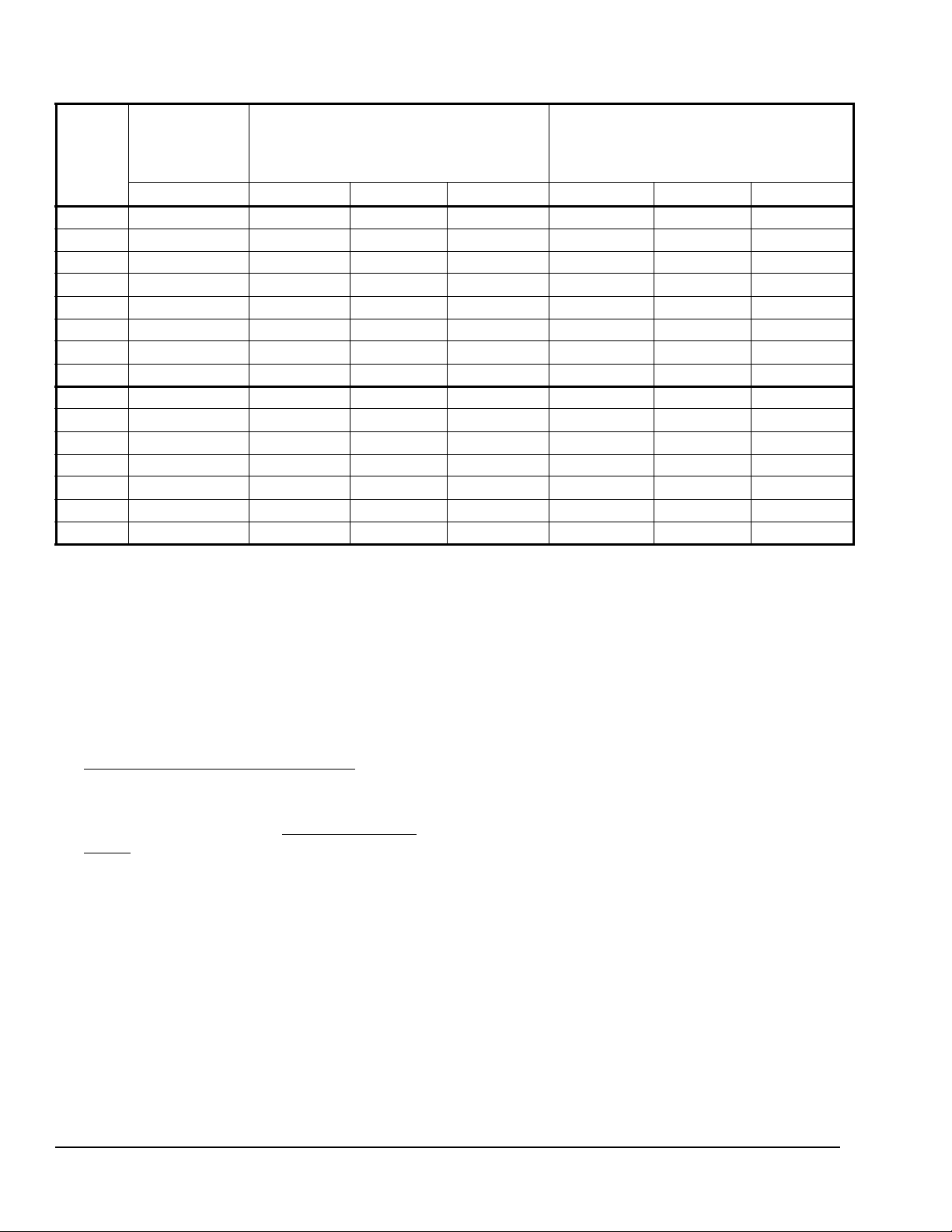
Table 1: Product Type High-Voltage Wiring Options and Voltage Ranges
Product
Type
Number
Split Winding/
Three Triac with
Low-Speed
Two Triac with
Low-Speed Capacitor
Single Triac
Capacitor
208/240 VAC 208/240 VAC 380/460 VAC 460/575 VAC 208/240 VAC 380/460 VAC 460/575 VAC
P266AA
P266AB
P266AC
P266AD
P266BC
P266BD
P266BG
P266BH
P266EA
P266EB
P266EC
P266ED
P266EE
P266EF
P266CH
See Figure 3A See Figure 3B -- -- See Figure 3C -- -See Figure 3A See Figure 3B -- -- See Figure 3C -- --
-- -- -- -- See Figure 3C -- --
-- -- -- -- See Figure 3C -- --
-- -- -- -- -- -- See Figure 3C
-- -- -- -- -- -- See Figure 3C
-- -- -- See Figure 3B -- -- See Figure 3C
-- -- -- See Figure 3B -- -- See Figure 3C
See Figure 4A See Figure 4B -- -- See Figure 4C -- -See Figure 4A See Figure 4B -- -- See Figure 4C -- --
-- -- -- -- See Figure 4C -- --
-- -- -- -- See Figure 4C -- --
-- -- -- -- See Figure 4C -- --
-- -- -- -- See Figure 4C -- --
-- -- See Figure 3B -- -- See Figure 3C
Setup and Adjustments
All P266 Series controls ship with factory-set default
values and mode settings. In most applications, the
default values and modes do not require field
adjustment.
If your P266 Series control application requires you to
change the value or mode settings, you must:
1. Calculate the new values and determine the new
mode settings required for your application. (See
P266 Series Control Values and Modes
2. Change the existing settings on the control to the
new values and modes using the P266 Series
control setup interface. (See Setting Values and
Modes.)
P266 Series Control Setup Interface
The P266 Series control setup interface consists of a
DIP switch block with eight binary switches, a push
button switch, and a green Light-Emitting Diod e (LED)
(Figure 2). You can change the factory-set default
values and modes by repositioning the DIP switches
and saving the new settings. The number of LED
flashes (in sequence) indicates which value and/or
modes that you are saving. See Table 2 for more
information about LED flash sequences, values, and
modes.
.)
During normal operation, the green LED is on. When
you press and hold the push button, the LED goes off
for 3 seconds then flashes two times. The LED then
goes off again for 3 seconds and flashes three times,
and continues in this pattern until seven flashes or until
you release the push button.
Each sequence of flashes indicates a value or a value
and set of mode settings. Releasing the push button
after the desired flash sequence saves the value
and/or modes that are currently set on the DIP switch
block. See Table 2 for more information.
After you complete the setup, set all of the DIP
switches to the ON position to lock out the push button
operation.
P266 Series Control Values and Modes
P266 Series controls have up to ten values and modes
(in six flash sequences) that can be changed in the
field. See Table 2 for more information about flash
sequences and the associated values and modes.
Start Voltage Value
The start voltage (VAC) is the voltage delivered by the
P266 Series control to the fan motor to run the motor at
minimum speed in your application.
The Start Voltage value is a percentage of the P266
Series control’s input voltage. Use the following
formula to calculate the Start Voltage value for your
application.
P266 Series Single-Phase Condenser Fan Speed Control Installation Instructions4
Page 5
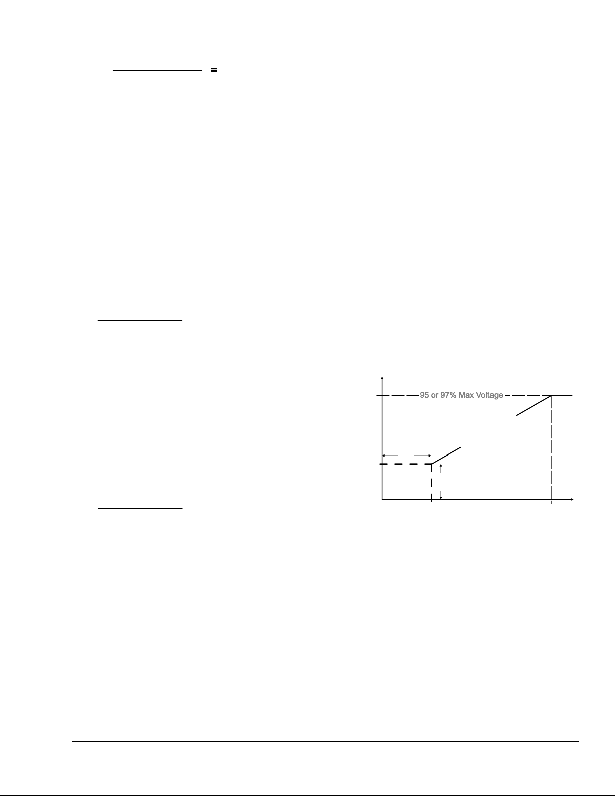
Start Voltage (VAC)
P266 Control
Start Voltage
Value (%)
P266 Transducer Pressure
Range (bar or psi)
X
=
Start Pressure
Value
P266 Transducer Pressure
Range (bar or psi)
X
=
End Pressure
Value
Figure 5: Relationship between
P266 Fan Speed Control Variables
Pressure
End
0
Start
Voltage
End
Voltage
Mode
Off
Low
Pressure
Mode
On
V
o
p
Input Line- Voltage (V AC)
Low Pressure Mode
Low Pressure Mode determines whether the fan motor
is either On (at start voltage/minimum speed) or Off
when the sensed pressure at the P266 transducer is
below the start pressure setpoint.
Start Pressure Value
Start pressure (psi or bar) is the pressure setpoint at
which the P266 Series control outputs the start voltage
and runs the fan motor at minimum speed. Start
Pressure value is a function of the start pressure
setpoint and the pressure range of the referenced
P266 transducer. Use the following formula to calculate
the Start Pressure value. See Table 3 for P266
transducer pressure ranges.
Start Pressure
Setpoint (bar or psi )
250
End Pressure Value
The end pressure setpoint is the pressure (bar or psi)
at which the P266 Series control outputs the End
Voltage and runs the fan motor at maximum speed.
End Pressure value is a function of the end pressure
setpoint and the total pressure range of the referenced
transducer. Use the following formula to determine your
application End Pressure value. See Table 3 for P266
transducer pressure ranges.
End Pressure
Setpoint (bar or psi )
250
Split Winding Mode
Some single-phase PSC motors have split motor
winding wire leads. Setting the Split Winding mode On
enables the M2 Triac to provide voltage to the main
windings (and not the auxiliary windings), which
increases motor efficiency (Figure 3A and Figure 4A).
Note: Split Winding mode is available for only
240 VAC single-phase PSC motors that have split
winding wire leads. Refer to the motor manufacturer’s
installation instructions to determine if your fan motor
may be wired to enabled the Split Winding mode.
Copeland Digital Scroll™ Compressor Mode
Digital Scroll Compressor Mode allows you to use the
P266 Series control on a system that uses a digital
scroll compressor. Failure to enable the digital scroll
compressor mode when using a digital scroll
compressor may cause your condenser fan to oscillate.
End Voltage Mode
End voltage is the voltage output by the P266 Series
control (as a percentage of the full voltage) that is
maintained when the monitored pressure is equal to or
greater than the End Pressure. The End Voltage mode
can be set to either 95% or 97% of the total input
voltage. See Figure 5.
r
g
a
t
l
Voltage to Motor
FIG:
266_Valu_Rels
Low Pre ssure Mode
Start
o
t
o
M
o
t
e
Pressure
Pressure at Sensor
P266 Series Single-Phase Condenser Fan Speed Control Installation Instructions 5
Page 6
Low-Speed Capacitor Mode
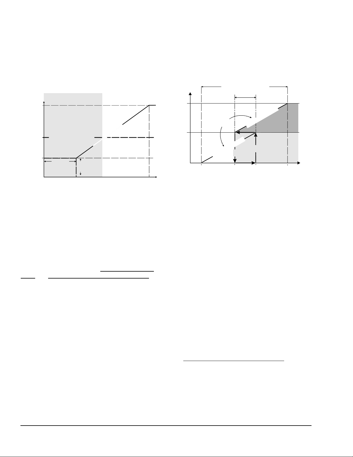
Figure 6: Low-Speed Capacitor Ope r ation
Pressure
End
0
Start
Voltage
End
Voltage
LPM
Off
LPM On
Low-Speed Capacitor
Enabled
Disabled
Chan geover Voltage
CV
FIG:
p
Figure 7: Speed-Controlle d (P266) Fan Opera ting
with One Auxiliary (On/Off) Fan Stage
over the Entire Pressure Range
Pressure
End
Pressure
0
Total
1st
Stage
P
2
6
6
F
a
n
O
u
t
p
u
t
Fan
Output
% Fan
Overlap
Plus
Output
P266 Fan
Stage
Shift
Fig:AuxFanOvrlap
In some fan speed applications, a (user-supp lied )
Low-speed capacitor (LSC) can be connected to the
P266 Series control’s M3 triac and the controlled fan
motor (Figure 3 and Figure 4). The low-speed capacitor
is enabled at low voltages to enhance the fan motor
efficiency and performance. Set Low-speed Capacitor
mode to On when a low-speed capacitor is used.
Low-Speed Capacitor
r
o
t
o
M
V
Voltage to Motor
266_CV_Rels
Start
Pressure at Se ns or
o
t
e
g
a
t
l
o
Pressure
Figure 7 shows a P266 Series control application with
one auxiliary fan operating in conjunction with the
speed-controlled fan. When the condenser load
exceeds the output capacity of the speed-controlled
fan, the P266 Series control powers On the auxiliary
fan and shifts the speed-co ntrolled (P266) fan to a n ew
start pressure.
Fan Throttling Range
t
u
p
t
Aux.Fan
u
O
n
a
F
6
6
2
P
Auxiliary
Off
Output Capacity
Start
On
P266 Fan
Pressure at Sensor
Note: The optional low-speed capacitor should be
equal in both the voltage range and the microfarad
value to the auxiliary capacitor supplied by the
manufacturer, but the capacitor must not exceed
15 microfarads.
Note: You must also set the Changeover Voltage
value when a low-speed capacitor is used in your P266
Series control application. See Changeover Voltage
Value and Determining Changeover Voltage Value for
more information on setting the Changeover Voltage
value.
Auxiliary Fan Stage Mode
You can set the P266 Series control to cycle (On/Off)
up to three additional (fixed-speed) fan motors or fan
stages in conjunction with the variable speed fan
controlled by the P266 Series control.
Three low-voltage circuits (Figure 2) can be wired to
control the auxiliary fan motor/stage starters. See
Table 2 for information on setting the number of
auxiliary fans used in your application.
P266 Series Single-Phase Condenser Fan Speed Control Installation Instructions6
Auxiliary Fan Overlap Value
Auxiliary Fan Overlap value determines the pressure
range overlap (as a percentage of the total pressure
[throttling] range) between the fan stages set up on the
P266 Series control. The fan overlap value is equal for
all auxiliary fan stages set up on the control.
Increasing the Auxiliary Fan Overlap value decreases
the (On/Off) cycling rate of the auxiliary fans and
increases the pressure differential between auxiliary
fan stages (which increases the pressure range of each
auxiliary fan stage).
Note: If the P266 Series control is set for no auxiliary
fans, the Auxiliary Fan Overlap value is not used. See
Table 2 for information on setting the number of
auxiliary fans used in your application.
Changeover Voltage Value
The Changeover Voltage value determines the voltage
at which the P266 Series control enables and disables
the M3 triac and the low-speed capacitor (Figure 6).
See Determining Changeover Voltage Value
.
Page 7
Setting Values and Modes
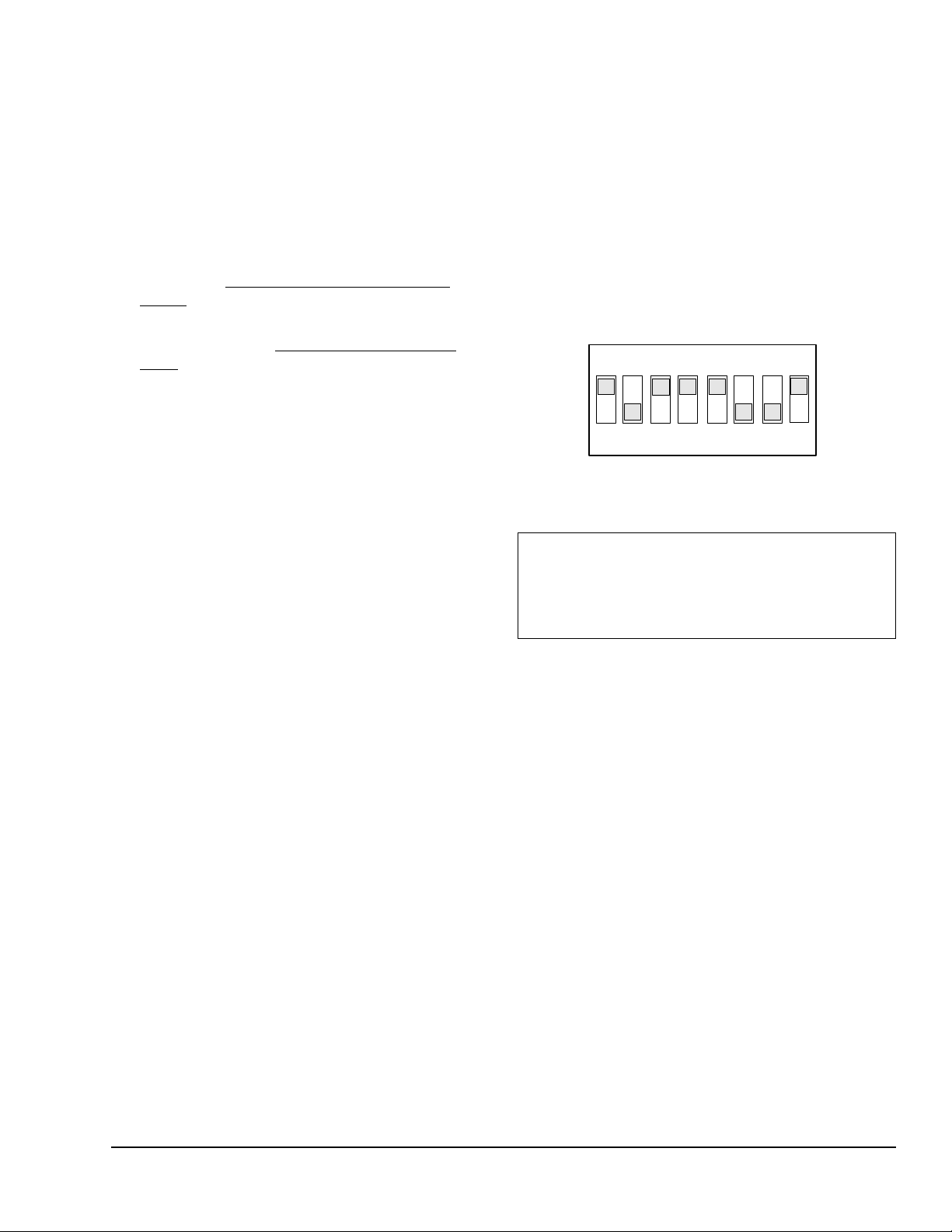
Figure 8: A DIP Switch Block with the
Switches Positioned for a Setup Value of 185
ON
FIG:p266_DIP_swtch
To change settings and values on a P266 Series
control:
1. Determine the operating pressure setpoints (psi or
bar), voltage inputs and outputs (VAC), and the
other modes of operation required for your
condenser fan motor control application.
2. Convert the selected pressure setpoints (psi or bar)
and voltage targets (VAC) into P266 Series control
values. See P266 Series Control Values and
Modes and Table 2.
3. Position the DIP switches to set the new values
and/or modes. See Setting up the DIP Switch
Block.
4. Press and hold the push button until th e number of
LED flashes indicates the desired value or set of
values and/or mode settings. Release the push
button after:
• two flashes to save the Low Pressure mo de
setting and the Start Voltage value
• three flashes to save the Start Pressure value
2. Position the numbered switches to ON so that the
total of the switch numbers (in the ON position)
equals the desired setup value. Start with the
highest number switch that is less than the setup
value. (For example, if the desired setup value is
185, position switch 128 to ON first. Then position
switch 32 ON, followed by switch 16, switch 8, and
switch 1 [128+32+16+8+1=185] [Figure 8]).
Mode settings require you to position only one or
two switches on the DIP switch block, depending
on the mode. See Table 2 for more information
about the values and modes that are associated
with the number of LED flashes.
8
32
64
128
16
4
1
2
• four flashes to save the End Pressure value
• five flashes to save the Split Winding,
End Voltage, Low-speed Capacitor Mode, and
Auxiliary Fan Stages mode settings
• six flashes to save the Auxiliary Fan Overlap
value
• seven flashes to save the Changeover
Voltage value
Note: See Table 2 for more information about the
values and modes that are associated with the
number of LED flashes.
5. Repeat Steps 3 and 4 for the next value and/or
mode you need to change.
6. After you save all of the new values and mode
settings, set all of the DIP switches to the On
position to lock out the push button operation.
Setting up the DIP Switch Block
To set new values and modes on the DIP switch block:
1. Position all of the switches on the DIP switch block
to the Off position.
IMPORTANT: All of the switches on the DIP switch
block must be set to the proper positions for your
application before you press and release the push
button to save the values and/or mode settings. See
Table 2 for more information on switch positions.
Test Voltage Mode
Test Voltage mode is a setup and diagnostic tool in the
P266 Series control firmware that allows you to test a
condenser fan motor’s operation at different voltage
values in the field and determine the optimal Start
Voltage value for your P266 Series control application.
Test Voltage mode also allows you to determine and
set the optimal Changeover Voltage value for the M3
triac in P266 Series control applications that use a
low-speed capacitor.
To use the Test Voltage Mode, you need:
• a P266 Series control model designed for your
condenser fan application
• access to the condenser (and fan motor) controlled
by your P266 Series control
• a clamp-on ampere meter with 15 A range (to
check changeover current draw when determining
Changeover Voltage value)
P266 Series Single-Phase Condenser Fan Speed Control Installation Instructions 7
• an insulated probe to hold down the push-button
and change the DIP switch positions
Page 8

• a 24 VAC Class 2 power supply (only for P266
Series control models that require an external
24 VAC power supply)
• a Low-Speed Capacitor (LSC), sized for the fan
motor (only for P266 Series control applications
that use a low-speed capacitor)
Note: The LSC should be equal in both the
voltage range and the microfarad value to the
motor manufacturer’s auxiliary capacitor, but the
LSC must not exceed 15 microfarads.
Setting up Test Voltage Mode
Before you power on a P266 Series control and enable
the Test Voltage mode on the control:
1. Read and follow the guidelines and procedures in
the Mounting
2. Mount and wire the P266 Series control in your
condenser application and observe these
additional guidelines:
• Refer to the label inside the P266 Series
control housing cover for model-specific wiring
details. See Wiring
• Wire the auxiliary and main windings according
to the motor manufacturer’s instructions and
your application requirements. Split the
windings (at the winding leads) and power
them separately, if your application and motor
allow for split-winding operation. See Figure 3
and Figure 4.
• If your application uses an optional low-speed
capacitor, wire the LSC to the M3 triac and
motor only after you have checked and
recorded the current draw at maximum. See
Determining Changeover Voltage Value
• If your P266 Series control model requires an
external 24 VAC power supply for control
operation, wire that power supply to the
control. (Refer to the wiring label inside the
P266 Series control cover for external power
supply requirements.)
•You do not have to connect, wire, or power the
P266 transducer, or put a load on the
condenser to operate a P266 Series control in
the Test Voltage mode. Test Voltage mode
allows you to use the DIP switch to set the
voltage supplied to the motor by the P266
Series control.
and Wiring sections.
for some wiring options.
.
3. Set up the P266 Series control and the condenser
fan motor for the intended operation, by setting the
required values and modes of operation for your
condenser fan application. See Setup and
Adjustments for procedures.
Determining Changeover Voltage Value
In the Test Voltage mode, you can determine and set
the Changeover Voltage value for P266 Series control
applications that use an optional low-speed capacitor.
To determine and set the Changeover Voltage value:
1. Mount, wire, and set up the P266 Series control
and the condenser fan motor for operation in the
Test Voltage mode. See Setting up Test Voltage
Mode.
Note: Do not wire the low-speed capa citor until
Step 6 of this procedure.
2. Set all of the DIP switches except switch 1 to the
ON position; set switch 1 to OFF.
3. Apply line-voltage power to the P266 Series control
(and the external 24 V AC p ower supply on required
models), then, within the first 30 seconds after
applying power , press and release th e push button
three times. The LED goes off and stays off, and
the fan motor accelerates to maximum speed (at
95 or 97% of maximum voltage) and stays at the
maximum voltage for up to 5 minutes.
4. At maximum voltage, use the clamp-on ampere
meter to check the current draw (in amperes) of the
fan motor auxiliary windings and record the
auxiliary windings current draw for the motor at
maximum voltage.
5. Disconnect line-voltage power to the P266 Series
control (and the external 24 VAC power supply on
required models).
6. Wire the low-speed capacitor to the M3 triac and
the motor auxiliary windings. (See Figure 3 and
Figure 4 for M3 triac wiring options.)
7. Set all of the DIP switches except switches 8 and
32 to the OFF position; set switches 8 and 32 to
the ON position. (8 + 32 = 40% of maximum
voltage value.)
8. Apply line-voltage power to the P266 Series control
(and the external 24 V AC p ower supply on required
models), then, within the first 30 seconds after
applying power , press and release th e push button
three times. The LED goes off and stays off, and
the fan motor accelerates to the speed at 40% of
the maximum voltage (for up to 5 minutes).
P266 Series Single-Phase Condenser Fan Speed Control Installation Instructions8
Page 9

9. At 40% of maximum voltage, use the clamp-on
ampere meter to check the current draw (in
amperes) of the fan motor auxiliary windings
connected to both capacitors and record the
current draw for the auxiliary winding at 40%
voltage.
10. Repeat Step 7 but increase the percent voltage
value by 8%, then repeat Step 8, Step 9, and
Step 10 at the increased voltage values until the
current draw equals the (maximum voltage) current
draw recorded in Step 4.
Note: If the motor stops or does not run smoothly,
reduce the voltage value on the DIP switches by
4% and test the motor operation.
11. The DIP switch voltage value is now equal to the
highest voltage of the low-speed mode or the
Changeover Voltage value.
12. Press and hold the push button until the LED
flashes 3 times, then release the button. The
Changeover Voltage value is set and saved on the
P266 Series control.
Note: If you want to also determine and set the
Start Voltage value for your P266 Series control
and motor, you can go directly to S tep 3 of the
Determining Start Voltage Value
13. Disconnect power to the P266 Series control and
set all of the DIP switches to the On position to lock
out the push button operation.
14. Reconnect power to the P266 Series control to
resume normal motor speed control.
Determining Start Voltage Value
In the Test Voltage mode, you can also determine and
set the Start Voltage value on for P266 Series control
application.
To determine and set the Start Voltage value:
1. Mount, wire, and set up the P266 Series control
and the condenser fan motor for operation in the
Test Voltage mode. See Setting up Test Voltage
Mode.
procedure.
Note: If your application uses Split Winding mode
and Low Speed Capacitor mode, wire the split
windings and low-speed capacitor according to
your application requirements (Figure 3A and
Figure 4A).
2. Apply line-voltage power to the P266 Series control
(and the external 24 V AC p ower supply on required
models), then, within the first 30 seconds after
applying power , p ress and r elease th e pu sh b utto n
three times. The LED goes off and stays off.
3. Position the DIP switches so that the total value of
the switches positioned ON is equal to a
percentage value equal to or slightly higher than
your estimated St art V oltage value. (For example, if
you estimate the start voltage of the motor to be
25% of the total voltage, position switches 16, 8 , 4,
and 2 ON. 16 + 8 + 4 + 2 = 30%, which is slightly
higher than your 25% estimate.) The fan motor
accelerates to the speed at 30% of maximum
voltage and stays at that speed.
4. Observe the fan motor opera tion an d de te rm in e if
the applied start voltage runs the motor at the
desired start speed:
• If the start speed and motor operation meet
your application requirements, go to Step 5.
• If the start speed or operation does not meet
your application requirements, return to Step 3
and set a new estimated Start Voltage value to
generate the desired motor start speed.
5. When your motor is running at the desired start
speed (Start Voltage value), press and hold the
push button until the LED flashes 2 times in
succession, then release the push button. The
Start Voltage value is set and saved on the P266
Series control.
6. Disconnect power to the P266 Series control and
set all of the DIP switches to the ON position to
lock out the push button operation.
7. Reconnect power to the P266 Series control to
resume normal motor speed control.
P266 Series Single-Phase Condenser Fan Speed Control Installation Instructions 9
Page 10
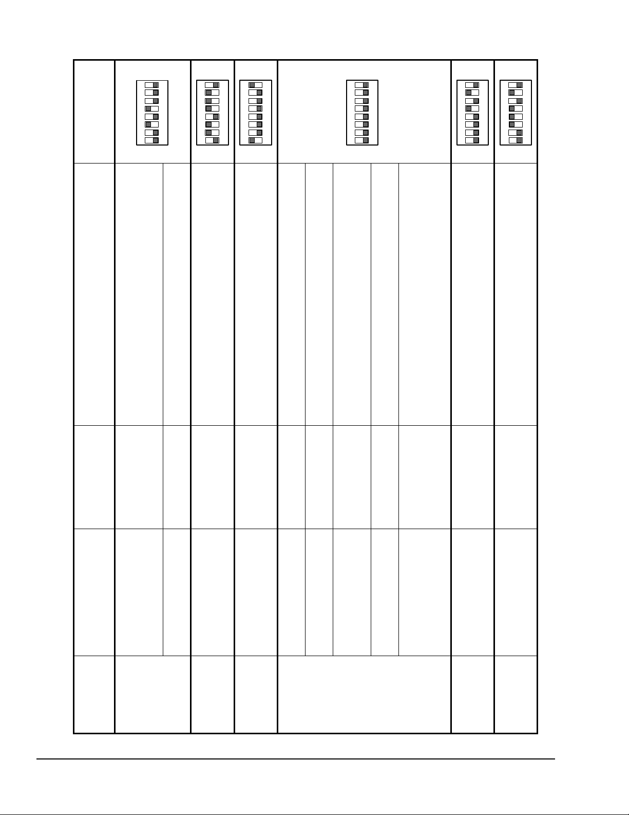
Table 2: LED Flash Sequences, Setup Values, Mode Settings on DIP Switch Block and Default Values and Mode Settings Example
Release
Push Button
After...
Value/Mode Name
(Binary Switch Number)
Value Range/Mode
Settings (Example
Default Settings)
Switch Number and Position
Description of Value/Setting
DIP Switch Block
Example Default
Settings
Two Flashes Low Speed Mode
(Switch 128)
Settings: ON or Off
(Default Setting:
Off
)
Switch 128 Off = No voltage to motor when sensed pressure is
below start pressure.
Switch 128 ON = Start voltage to motor when sensed pressure is
at or below start pressure.
Start Voltage Value
(Switches 1 to 64)
V alue Range: 10 to 90
(Default Value:
40
)
Position Switches 1 to 64 ON or Off so that the sum of the
switches set to ON equals the Start Voltage Value.
Three Flashes Start Pressure Value
(Switches 1 to 128)
V alue Range: 10 to 230
(Default Value:
110
)
Position Switches 1 to 128 ON or Off so that the sum of the
switches set to ON equals the Start Pressure Value.
Four Flashes End Pressure Value
(Switches 1 to 128)
V a lue Range: [Start
Pressure + 8] to 240
(Default Value:
129
)
Position the Switches 1 to 128 ON or Off so that the sum of the
switches set to ON equals the End Pressure Value.
Five Flashes
(Switches 64 and
128 Off)
Split Winding Mode
(Switch 32)
Settings: ON or Off
(Default Setting:
Off
)
Switch 32 ON = M2 Triac enabled to power split windings.
Switch 32 Off = M2 Triac is disabled.
End Voltage Mode
(Switch 16)
Settings: ON or Off
(Default Setting:
Off
)
Switch 16 ON = Provides 95% of P266 input voltage to motor.
Switch 16 Off = Provides 97% of P266 input voltage to motor.
Digital Scroll Compressor
Algorithm
(Switch 8)
Settings: ON or Off
(Default Setting:
Off
)
Switch 8 ON = Digital Scroll algorithm enabled.
Switch 8 Off = Digital Scroll algorithm disabled.
Low Speed Capacitor Mode
(Switch 4)
Settings: ON or Off
(Default Setting:
Off
)
Switch 4 ON = Low-speed capacitor is available.
Switch 4 Off = Low-speed capacitor is not available.
Number of Auxiliary Fan
Stages
(Switches 1 and 2)
Settings: ON or Off
(Default Setting:
Off -
Off
)
Position switches 1-Off and 2-Off for no auxiliary fans.
Position switches 1-On and 2-Off for auxiliary fan 1.
Position switches 1-Off and 2-On for auxiliary fans 1 and 2.
Position switches 1-On and 2-On for auxiliary fan 1, 2, and 3.
Six Flashes
(Switch 128 Off)
Auxiliary Fan Overlap
(Switches 1 to 64)
V alue Range: 1 to 90
(Default Value:
10
)
Position Switches 1 to 64 ON or Off so that the sum of the
switches set to ON equals the Auxiliary Fan Overlap Value.
Seven Flashes
(Switch 128 Off)
Changeover Voltage Value
(Switch 1 to 64)
Value Range: 10 to 80
(Default Value: 60)
Position Switches 1 to 64 ON or Off so that the sum of the
switches set to ON equals the Changeover Voltage value.
ON
ON
ON
ON
ON
ON
1
2
4
8
16
32
64
128
1
2
4
8
16
32
64
128
1
2
4
8
16
32
64
128
1
2
4
8
16
32
64
128
1
2
4
8
16
32
64
128
1
2
4
8
16
32
64
128
P266 Series Single-Phase Condenser Fan Speed Control Installation Instructions10
Page 11
P266 Electronic Pressure Transducers
P266 Series controls are designed to reference either
one or two Johnson Controls P266 Electronic Pressure
Transducers to monitor condenser pressure.
P266 transducers are specialized versions of the
P499 Series Electronic Pressure Transducers
designed for use with P266 Series controls. See
Table 3 for the available P266 transducer models.
Note: On P266 Series control applications that use
two P266 transducers, the P266 Series control always
references the transducer that is sensing the highest
pressure.
IMPORTANT: When two P266 transducers are
connected to a P266 Series control, the transducers
Refer to the P499 Series Electronic Pressure
T ransducers Product/Technical Bulletin (LIT-1201 1190)
for information on installing P266 transducers.
Table 3: P266SNR Electronic Pressure
Transducers
Product
Description
Code
Number
P266SNR-1C Electronic Pressure Transducer:
0 to 35 bar (0 to 508 psi) total range
with a 1/4 in. SAE Female Flare
connection and a 2 meter (3.1 ft) cable.
P266SNR-2C Electronic Pressure Transducer:
0 to 52 bar (0 to 754 psi) total range
with a 1/4 in. SAE Female Flare
connection and a 2 meter (3.1 ft) cable.
must be the same model (product code number).
Failure to connect the same P266 transducer
models to the P266 Series control can result in
erratic control behavior.
Technical Specifications
P266xxx-x Single-Phase Condenser Fan Speed Control
Input Supply Power 208/240 VAC 50/60 Hz, 380/460 VAC 50/60 Hz, or 480/575 VAC 50/60 Hz depending on
model (Refer to the label inside the P266 control housing cover for rated voltage range and
model-specific wiring diagram.)
Short Circuit Current
Rating
Low-Voltage Power
Supply
Ambient Operating
Conditions
Ambient Shipping and
Storage Conditions
Low-Voltage Connections 1/4 in. Quick-Connect terminals, 30 m (100 ft) maximum wiring runs
Input Transducer P266SNR-x Pressure Transducer: 5 VDC for 0.5 to 4.5 VDC ratiometric analog signal
Enclosure Type NEMA 3R, IP54
Case Construction Aluminum Die Casting
Cover Construction UV Stabilized Polycarbonate
Dimensions (HxWxD) 159 x 177 x 70 mm (6-1/4 x 7 x 2-3/4 in.)
Weight Heaviest Model Weight: 1.0 kg (2.2 lb)
Compliance North America: cULus File 244421;
Suitable For Use On A Circuit Capable Of Delivering Not More Than 5,000 rms Symmetrical
Amperes, 600 Volts Maximum When Protected By Class H Fuses.
P266A, P266B, and P266C Types: External 24 VAC Class 2, 20 VA Supply Transformer
P266Exx Types: Low-voltage power for P266 control is provided by an onboard transformer.
Note: When auxiliary fan starters are connected to P266E type controls, you must provide an
external Safety Extra-Low Voltage (SELV) AC supply to power the fan starters (Figure 2).
T emperature: -40 to 60°C (-40 to 140°F)
Humidity: Up to 95% RH non-condensing; Maximum Dew Point 29°C (85°F)
T emperature: -40 to 85°C (-40 to 185°F)
Humidity: Up to 95% RH non-condensing; Maximum Dew Point 29°C (85°F)
Approximate Shipping Weight: 1.2 kg (2.6 lb)
FCC Compliant to CFR47, Part 15, Subpart B, Class B
Industry Canada (IC) Compliant to Canadian ICES-003, Class B limits
Europe: CE Mark – Johnson Controls, Inc., declares that the P266 Series Single-Phase
Condenser Fan Speed Controls are in compliance with the essential requirements and other
relevant provisions of the EMC Directive 2004/108/EC and Low Voltage Directive 2006/95/EC.
Australia: C-Tick Compliant (N1813)
P266 Series Single-Phase Condenser Fan Speed Control Installation Instructions 11
Page 12

Metasys® and Johnson Controls® are registered trademarks of Johnson Controls, Inc.
All other marks herein are the marks of their respective owners. © 2010 Johnson Controls, Inc.
Building Efficiency
507 E. Michigan Street, Milwaukee, WI 53202
The performance specifications are nominal and conform to acceptable industry standards. For application at conditions beyond these
specifications, consult Johnson Controls Application Engineering at (414) 524-5535. Johnson Controls, Inc. shall not be liable for damages
resulting from misapplication or misuse of its products.
United States Emissions Compliance (FCC)
This equipment has been tested and found to comply with the limits for a Class B digital device, pursuant to Part 15 of the FCC Rules. These
limits are designed to provide reasonable protection against harmful interference in a residential installation. This equipment generates, uses
and can radiate radio frequency energy and, if not installed and used in accordance with the instructions, may cause harmful interference to
radio communications. However, there is no guarantee that interference will not occur in a particular installation. If this equipment does cause
harmful interference to radio or television reception, which can be determined by turning the equipment off and on, the user is encouraged to try
to correct the interference by one or more of the following measures:
- Reorient or relocate the receiving antenna.
- Increase the separation between the equipment and receiver.
- Connect the equipment into an outlet on a circuit different from that to which the receiver is connected.
- Consult the dealer or an experienced radio/TV technician for help.
Canadian Emissions Compliance
This Class (B) digital apparatus meets all the requirements of the Canadian Interference-Causing Equipment Regulations.
Cet appareil numérique de la Classe (B) respecte toutes les exigences du Règlement sur le matériel brouilleur du Canada.
P266 Series Single-Phase Condenser Fan Speed Control Installation Instructions12
Published in U.S.A. www.johnsoncontrols.com
 Loading...