

Page 1

M9208-AGx-x Series On/Off and Floating Point Electric
Spring Return Actuators
Installation Instructions
M9208-AGA-3, M9208-AGC-3, M9208-AGA-2
Refer to the QuickLIT Web site for the most up-to-date version of this document.
Part No. 34-636-2170, Rev. B
Issued May 13, 2011
Supersedes March 10, 2009
Applications
The M9208-AGx-x Series On/Off and Floating Point
Electric Spring Return Actuators are direct-mount
actuators that operate on AC/DC 24 V power. These
bidirectional actuators do not require a damper linkag e,
and are easily installed on round shafts from
5/16 to 5/8 in. (8 to 16 mm) or square shafts from
1/4 to 1/2 in. (6 to 12 mm) using the standard shaft
clamp included with the actuator. An optional
M9208-600 Large Coupler Kit is available for round
shafts from 1/2 to 3/4 in. (12 to 19 mm) or square
shafts from 3/8to9/16in.(10to14mm).
A single M9208-AGx-x Series On/Off and Floating
Point Electric Spring Return Actuator provides
70 lb·in. (8 N·m) running and spring return torque.
Integral line voltage auxiliary switches, available only
on the M9208-xxC-3 models, indicate end-stop
position, or perform switching functions within the
selected rotation range.
M9208-AGA-2 actuators include plenum-rated cables
and are specially configured for installation in spaces
used for environmental air-handling purposes other
than ducts and plenums as specified in National Fire
Protection Association (NFPA) 70: National Electrical
Code section 300.22(C), Other Space Used for
Environmental Air . The sp ace over a hung ceiling used
for environmental air handling purposes is an example
of the type of space for which these actuators are
configured.
IMPORTANT: Use this M9208-AGx-x Series
On/Off and Floating Point Electric Spring Return
Actuator only to control equipment under normal
operating conditions. Where failure or malfunction of
the electric actuator could lead to personal injury or
property damage to the controlled equipment or
other property, additional precautions must be
designed into the control system. Incorporate and
maintain other devices, such as supervisory or
alarm systems or safety or limit controls, intended to
warn of or protect against failure or malfunction of
the electric actuator.
Installation
The M9208-AGx-x Series On/Off and Floating Point
Electric Spring Return Actuators mount directly to the
surface in any convenient orientation using two
No. M3.5 x 9.5 mm self-drilling sheet metal screws and
the anti-rotation bracket (parts included with the
actuator). No additional linkages or couplers are
required. Electrical connections are color-coded and
identified with numbers permanently marked on the
actuator cable. A tag on the actuator cable identifies
the electrical connections and wiring details are
included on the actuator housing.
IMPORTANT: Before specifying M9208-AGx-x
Series On/Off and Floating Point Electric Spring
Return Actuators for plenum applications, verify
acceptance of exposed plastic materials in plenum
areas with the local building authority. Building
codes for plenum requirements vary by location.
Some local building authorities accept compliance to
UL 1995, Heating and Cooling Equipment, while
others use different acceptance criteria.
IMPORTANT: Do not install or use this
M9208-AGx-x Series On/Off and Floating Point
Electric Spring Return Actuator in or near
environments where corrosive sub stances or va pors
could be present. Exposure of the electric actuator
to corrosive environments may damage the internal
components of the device, and will void the
warranty.
Parts Included
• M9208-AGx-x actuator
• M9208-603 adjustable stop kit
• M9000-604 anti-rotation bracket with two
No. M3.5 x 9.5 mm, pan-head, cross-recessed
(Phillips), self-drilling and self-tapping screws
• Manual override crank with 3M® Dual Lock®
adhesive-backed strip
• Two No. 10-32 x 9/16 in. conduit connector screws
Special Tools Needed
• 10 mm wrench/socket
• drill with Phillips bit, driver size 1
M9208-AGx-x Series On/Off and Floating Point Electric Spring Return Actuators
Installation Instructions
1
Page 2
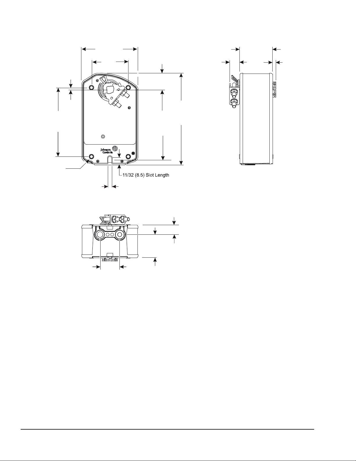
Dimensions
Figure 1: M9208-AGx-x Series On/Off and Floating Point Electric Spring Return Actuator
Dimensions, in. (mm)
(34.5)
(40.7)
21/32
(16.7)
3/4 (19)
2-1/4 (57.5)
(99)
2-9/16
(64.5)
1/8
(3.2)
4-3/4
(120.7)
1-1/8
(28.5)
4-29/32
(124.8)
6-5/16
(160.7)
1/4 (6.5) Sl ot Wi dth
4 Mounting Holes
4-7/32 (5. 45)
Diameter
3-29/32
1/4 (6.4)
1-3/8
1-19/32
FIG:M9208-Dims
M9208-AGx-x Series On/Off and Floating Point Electric Spring Return Actuators Installation Instructions2
Page 3

Accessories
Table 1: Accessories and Replacement Parts (Order Separately)
Code Number Description
DMPR-KC003
M9000-200 Commissioning T ool that provides a control signal to drive 24 V On/Off, Floating, Proportional, and/or
M9000-321 Weathershield Kit for Damper Application of M9203 and M9208 Series Electric Spring Return
M9000-400 Jackshaft Linkage Kit. Open-ended design enables clamping onto a jackshaft without requiring
M9000-560 Ball Valve Linkage Kit for applying M9203 and M9208 Series Electric Spring Return Actuators to
M9000-604 Replacement Anti-Rotation Bracket Kit for M9208, M9210, and M9220 Series Electric Spring Return
M9000-606 Position Indicator for Damper Applications of M9203 and M9208 Series Actuators (quantity 5)
M9200-100 Threaded Conduit Adapter, 1/2 NPSM, for M9210(20) and M(VA)9208 Series Actuators (quantity 5)
M9208-100 Remote Mounting Kit, including Mounting Bracket, M9208-150 Crankarm, Ball Joint, and mounting
M9208-150 Crankarm Adapter Kit (quantity 1)
M9208-600 Large Shaft Coupler Kit (with Locking Clip) for Mounting M9208 Series Electric Spring Return
M9208-601 Replacement Standard Coupler Kit (with Locking Clip) for mounting M9208 Series Electric
M9208-602 Replacement Locking Clips for M9208 Series Electric Spring Return Actuators (quantity 5)
M9208-603 Adjustable Stop Kit for M9208 Series Electric Spring Return Actuators (quantity 1)
M9208-604 Replacement Manual Override Cranks for M9208 Series Electric Spring Return Actuators
M9208-605 Replacement Manual Override Cranks for M9208 Series Electric Spring Return Actuators
1
7 inch- (178 mm-) Blade Pin Extension (without bracket) for Johnson Controls® Direct-Mount
Damper Applications (quantity 1)
Resistive Electric Actuators (quantity 1)
Actuators (quantity 1)
access to the ends of the jackshaft. (quantity 1)
VG1000 Series Valves (quantity 1)
Actuators (quantity 1)
fasteners (quantity 1)
Actuators on dampers with round shafts from 1/2 to 3/4 in. (12 to 19 mm) or square shafts from
3/8to9/16in.(10to14mm) (quantity 1)
Spring Return Actuators on dampers with round shafts from 5/16 to 5/8 in. (8 to 16 mm) or square
shafts from 1/4 to 1/2 in. (6 to 12 mm) (quantity 1)
with long crank radius: 2.83 in. (72 mm) (quantity 5)
with short crank radius: 1.83 in. (46.5 mm) (quantity 5)
1. Furnished with the damper and may be ordered separately.
M9208-AGx-x Series On/Off and Floating Point Electric Spring Return Actuators Installation Instructions 3
Page 4
Mounting
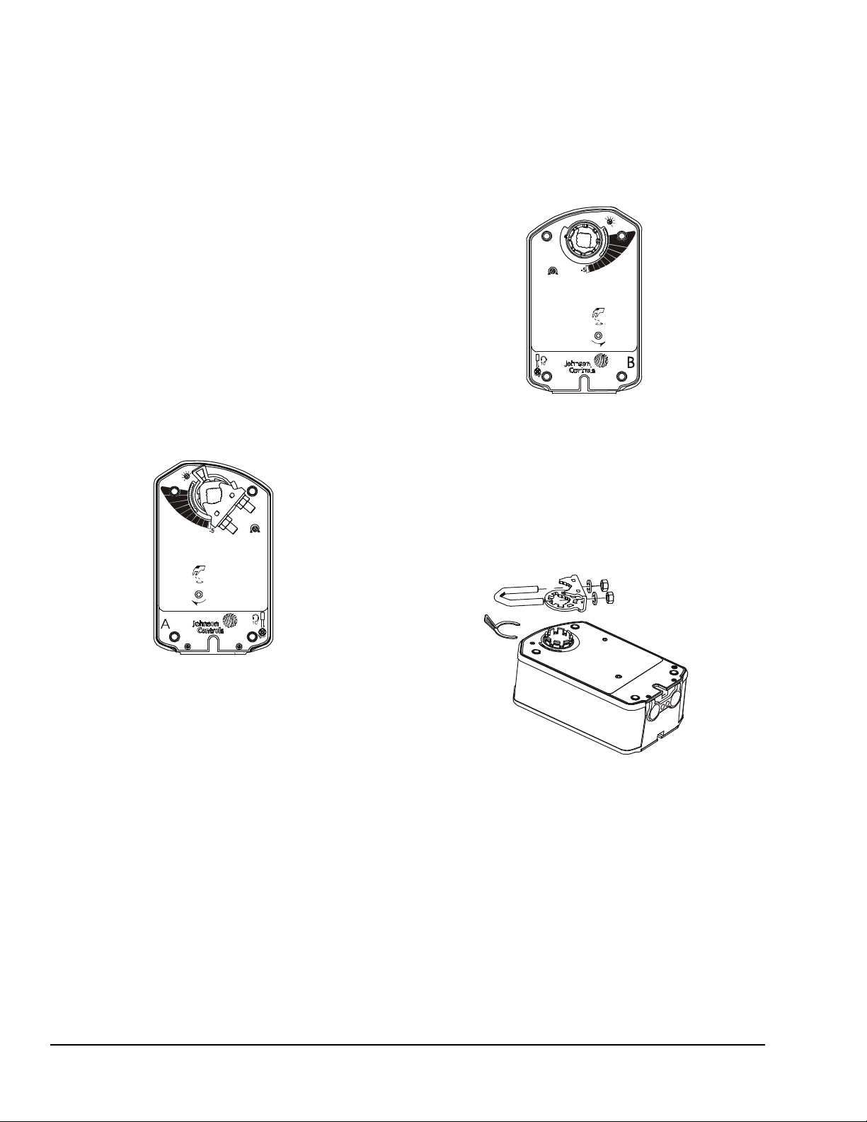
Figure 2: Actuator Side A
FIG:M920 8_AGx_Side_A
Figure 3: Actuator Side B
FIG:M9208_AGx_Side_B
8
.
5
x
DARA
Figure 4: Changing the Coupler Position
FIG:Chng_ PosnCplr_
The M9208-AGx-x Series On/Off and Floating Point
Electric Spring Return Actuators can be easily installed
on dampers with round shafts from 5/16 to 5/8 in.
(8 to 16 mm) or square shafts from 1/4 to 1/2 in.
(6 to 12 mm) using the standard shaft coupler included
with the actuator. An optional M9208-600 Large Shaft
Coupler Kit adapts to larger shaft sizes; se e Table 1 for
more details. If the damper shaft extends less than
3.31 in. (84 mm), see the Removable Coupler section
for further instructions. If the damper shaft extends less
than 0.79 in. (20 mm), install a shaft extension
recommended by the damper manufacturer.
Counterclockwise (CCW) Spring Return Direction – Clockwise (CW) Powered Operation
For CCW spring return direction, mount the actuator to
the damper shaft so that Side A of the actuator is away
from the damper as illustrated in Figure 2. With power
applied, the actuator drives CW from the 0° position
and spring returns CCW.
RA
DA
x
8
5
.
Clockwise (CW) Spring Return Direction – Counterclockwise (CCW) Powered Operation
For CW spring return direction, mount the actuator to
the damper shaft so that Side B of the actuator is away
from the damper as illustrated in Figure 3. With power
applied, the actuator drives CCW from the 0° position
and spring returns CW.
90
Removable Coupler
If the damper shaft extends less than 3.31 in. (84 mm),
mount the coupler on the face of the actuator closest to
the damper.
If the damper shaft extends less than 0.79 in. (20 mm),
a shaft extension is required to mount the actuator.
M9208-AGx-x Series On/Off and Floating Point Electric Spring Return Actuators Installation Instructions4
To change the coupler’s position, see Figure 4 and
proceed as follows:
1. Mount the coupler on either Side A or Sid e B of the
actuator as determined by the shaft length.
2. Snap the locking clip securely into the coupler
retention groove to retain the coupler.
Page 5
Manual Override
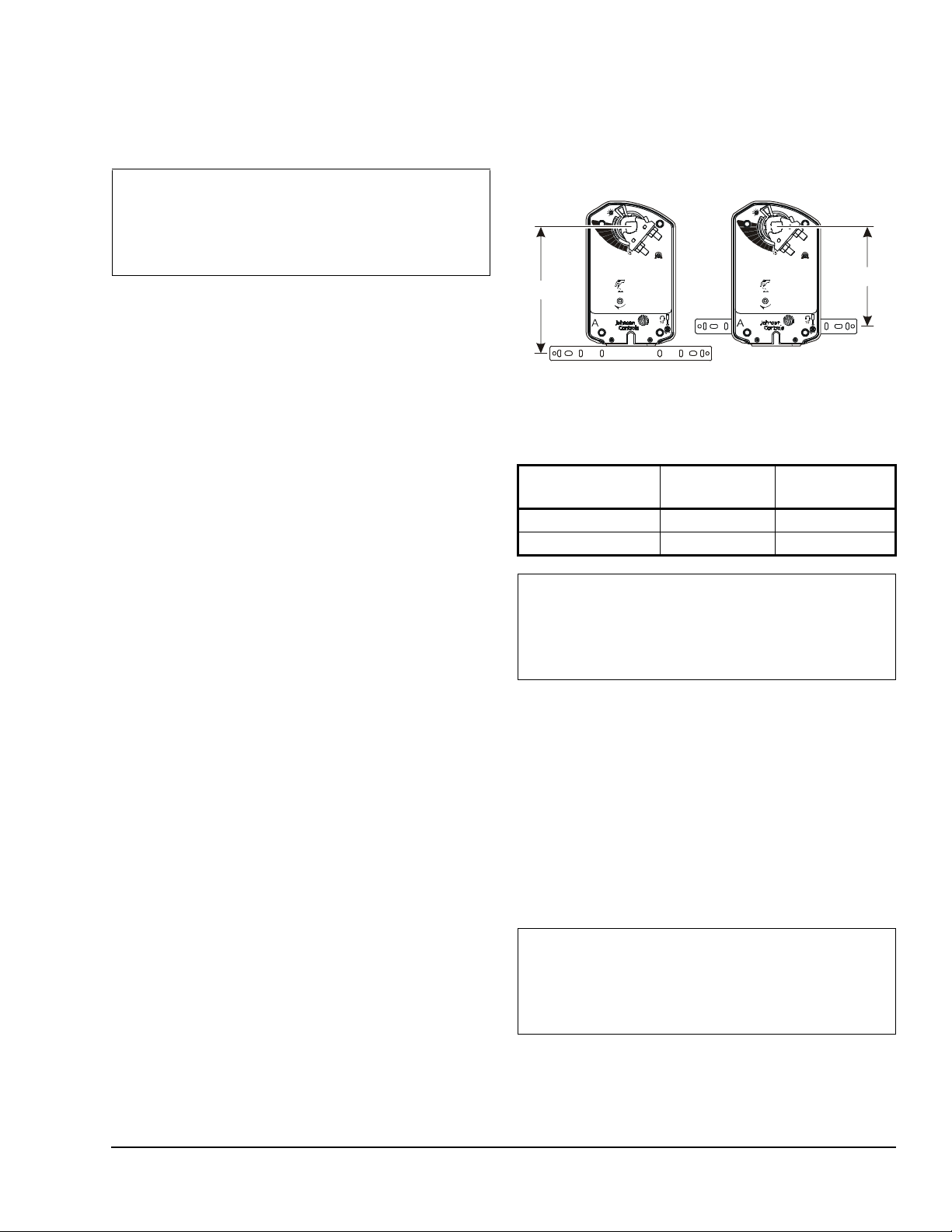
Figure 5: Positioning the Anti-Rotation Bracket
FIG:M9208 _AGx_Position_Brkt
8
.
5
x
D
I
M
.
A
D
I
M
.
DA
RA
DA
RA
Use only the supplied manual override crank to
reposition the actuator hub when using the manual
override feature.
IMPORTANT: Applying excessive torque to the
manual override or operating the manual override
with a power tool may damage the internal
components of the actuator and cause premature
failure.
To reposition the actuator hub, proceed as fo llows:
1. De-energize the actuator.
2. Insert the hex end of the manual override crank
into the manual override adjustment point on the
face of the actuator.
3. Rotate the manual override crank in the direction
indicated by the arrow on the label.
4. The actuator requires 8-1/2 manual override crank
rotations from the full spring return position to fully
reposition the actuator hub. At the end of travel, the
rotation resistance increases. Do not force the
manual crank past this point.
5. While holding the manual crank in the wound
position, rotate and hold the red lock shaft
approximately 10° then release the manual crank
to lock the actuator hub in place.
Note: Insert and slightly rotate the manual crank
in the direction indicated by the arrow on the label
to unlock the actuator hub. Alternatively, the
actuator hub automatically unlocks when power is
applied to the actuator, and returns the actuator to
normal drive and spring return operation.
Mounting the Actuator
To mount the actuator, proceed as follows:
1. See the dimensions in Figure 5 and Table 2 to
ensure the correct positioning of the anti-rotation
bracket.
8
.
5
x
Table 2: Dimensions from Anti-Rotation Bracket
to Shaft Center
Shaft Diameter,
in. (mm)
5/16 to 5/8 (8 to 16) 5-7/16 (138.4) 4-5/32 (105.6)
1/2 to 3/4 (12 to 19) 5-13/32 (137.4) 4-1/8 (104.6)
IMPORTANT: The tab on the anti-rotation bracket
must fit midpoint in the actuator slot. Positioning the
tab midpoint in the slot prevents actuator binding
and premature wear, and makes actuator removal
easier.
2. Bend or cut the anti-rotation bracket to fit the
damper frame or duct as illustrated in Figure 6.
Note: The anti-rotation bracket can be bent to fit a
round damper.
Dimension A,
in. (mm)
Dimension B,
in. (mm)
B
M9208-AGx-x Series On/Off and Floating Point Electric Spring Return Actuators Installation Instructions 5
3. Mark or drill mounting holes in the damper frame or
duct using the anti-rotation bracket as a guide
(based on the measurements obtained in Table 2
and Figure 5).
4. Secure the anti-rotation bracket to the damper
frame or duct using the two No. M3.5 x 9.5 mm
self-drilling sheet metal screws provided.
IMPORTANT: Do not overtighten the mounting
screws to avoid stripping the threads. Be certain that
the tab on the anti-rotation bracket remains properly
positioned in the slot on the actuator, and that the
actuator remains parallel to the mounting surface.
5. Slide the actuator onto the damper shaft, and
position the anti-rotation bracket tab into th e slot at
the bottom of the actuator as illustrated in Figure 6.
Page 6
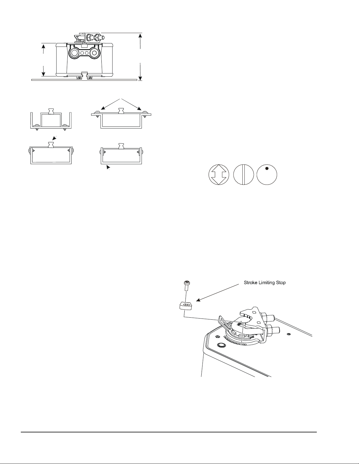
Figure 6:
Anti-Rotation Mounting Bracket Positions
FIG:M9208_ Anti-Rotn_Mntg_Brkt_Posn
2-1/4
(57.5)
3-9/32
Damper Frame
Figure 7: Damper Position Icons
FIG:dampers
FIG
Figure 8: Limiting Rotation Range
FIG:M9208-Strk_Lmtg_Stop_Opaq_Brkt
(83.5)
Self-Drilling Sheet Metal Screws (2)
Anti-Ro t at ion Bracket
6. Rotate the damper blade(s) to the desired position
if the power is lost. To ensure a tight seal, insert the
manual override crank and turn it in the direction
indicated by the arrow. The position indicator
should be near the 0° position on the scale. While
holding the manual crank in the wound position,
rotate and hold the red lock shaft approximately
10° then release the manual crank to temporarily
lock the actuator hub in place.
7. Hold the actuator perpendicular to the damper
shaft. Evenly hand-tighten each nut on the coupler
U-bolt, then torque the coupler U-bolt nuts to
100 to 125 lb·in. (11 to 14 N·m).
Note: If electric power is not available, complete
this verification by reinserting the manual override
crank and turning it in the direction indicated to
rotate the hub to the fully open position.
Limiting Rotation Range Using M9208-603 Adjustable Stop Kit
The actuator is factory set for 95° rotation, and its
range is limited in 5° increments to a minimum of 35° . A
stroke-limiting stop can be attached in the field to the
shaft coupler side of the actuator to redu ce the rot ation
range. Attaching the stroke-limiting stop in the furthest
mounting position reduces the rotation range of the
actuator by 5°. Each progressive mounting position
reduces the rotation range an additional 5°.
1. Check that the damper blade is visible or its
position is permanently marked on the end of the
damper shaft, as illustrated in Figure 7.
:dampos
2. Position the stroke-limiting stop in the serrated slot
with its leading edge at the scale position matching
the desired stroke.
3. The product label marks hole positions for the
M3-0.5 x 8 mm self-tapping screw provided with
the adjustable stop kit. Drive the screw through the
slot in the adjustable stop and into the actuator
face over a marked hole position. (See Figure 8.)
Note: The minimum rotation range is 35°.
8. To manually unlock the actuator hub, rotate the
9. Store the manual override crank by applying the
10. Apply power long enough for the actuator to travel
manual override crank slightly in the direction
indicated by the arrow and remove it. Alternatively,
the hub automatically unlocks when power is
applied to the actuator.
3M Dual Lock adhesive-backed strip to the manual
crank and a convenient surface of the actuator.
a full stroke. Verify that the actuator rotates freely
throughout the range.
M9208-AGx-x Series On/Off and Floating Point Electric Spring Return Actuators Installation Instructions6
Page 7
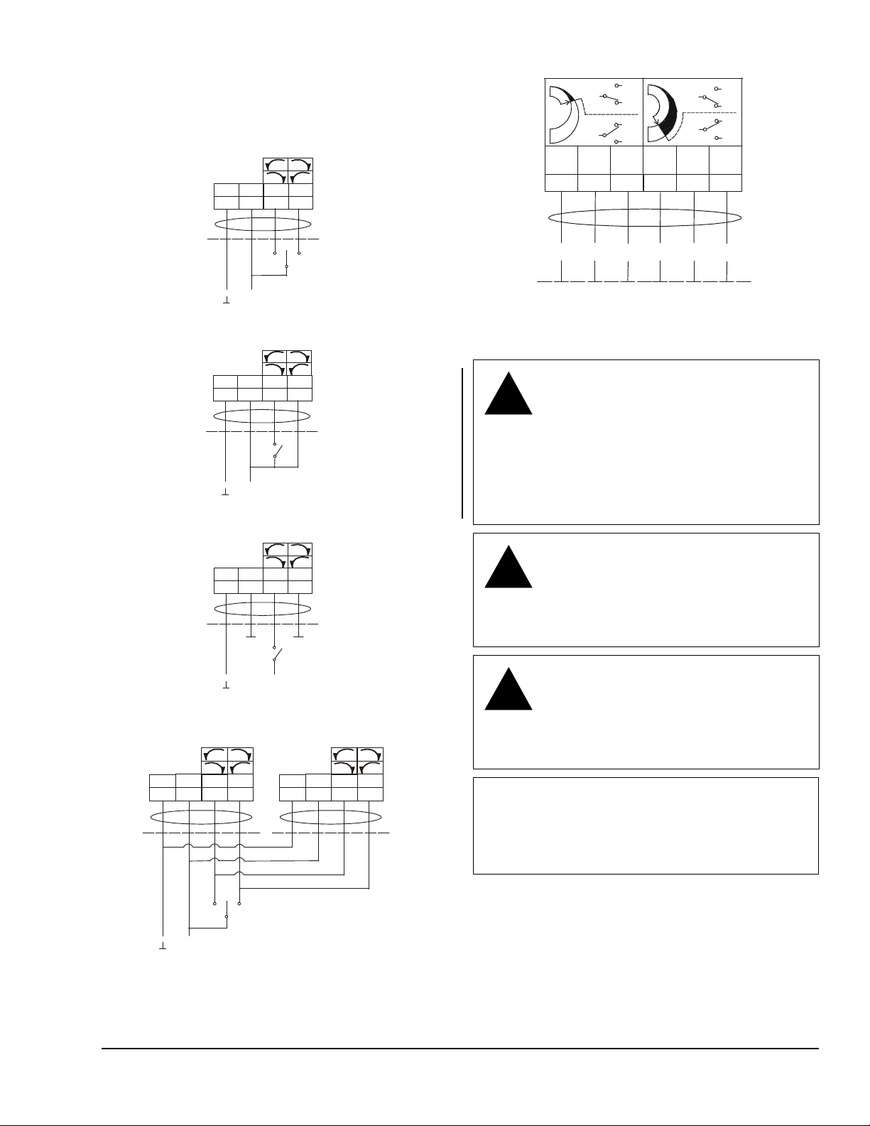
Wiring
Figure 9: Control Wiring Diagrams
~
+
-
RA
RA
DADA
BLK
1
2
3
+
-
24 VAC
24 VDC
BLK
12
3
~
+
-
BLK
1
2
3
FIG:M92x x-AGx_cntrlwir
24 VAC
24 VDC
~
4
BLK
RED
GRY
ORN
1
2
3
1
2
3
!
!
!
Figure 10: Auxiliary Switch Wiring Diagram
NC
NO
21
21
23
22
21
22
23
BLK/
RED
BLK/
BLU
BLK/
GRY
COM
NC
NO
24
WHT/
RED
WHT/
BLU
WHT/
GRY
25
24
24
S2
S1
FIG:xxC_Switch_Wiring
See Figure 9 and Figure 10 to wire the applicable
M9208-AGx-x Series model.
Floating Control, Four Wire
RED
Floating Control, Mul tiple Actuators with One Transfor me r
Open /Close, Single Wire Con trol
RED
On/Off Control, Two Wire
RED
RA
RA
DADA
GRY
RA
GRY
RA
GRY
~
ORN
24 VAC
24 VDC
RA
ORN
24 VAC
24 VDC
RA
ORN
BLK
4
DADA
4
DADA
4
RA
RED
GRY
RA
DADA
ORN
4
26
25
26
COM
WARNING: Risk of Electric Shock.
Disconnect or isolate all power supplies
before making electrical connections.
More than one disconnect or isolation
may be required to completely
de-energize equipment. Contact with
components carrying hazardous voltage
can cause electric shock and may result
in severe personal injury or death.
CAUTION: Risk of Property Damage.
Do not apply power to the system before
checking all wiring connections. Short
circuited or improperly connected wires
may result in permanent damage to the
equipment.
CAUTION: Risk of Property Damage.
Insulate and secure each unused wire
lead before applying power to the
actuator. Failure to insulate and secure
each unused wire lead may result in
property damage.
IMPORTANT: Make all wiring connections in
accordance with the National Electrical Code and
local regulations. Use proper Electrostatic Discharge
(ESD) precautions during installation and servicing
to avoid damaging the actuator’s electronic circuits.
-
+
M9208-AGx-x Series On/Off and Floating Point Electric Spring Return Actuators Installation Instructions 7
Page 8
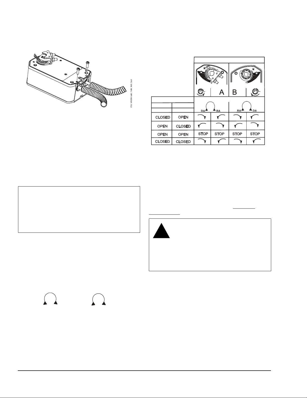
Using Conduit
Figure 11: Adding Flexible Metal Conduit
Figure 12: Mode Selection
FIG:AGx
Side A of Actuator Side B of Actuator
DA
RA
DARA
!
Figure 13: Control Response
FIG:M92xxAGx_CtrlRs pns
GRY ORN
34
All M9208 Series Actuators accept 3/8 in. trade size
flexible metal conduit.
Control Response
The installation side of the actuator and the position of
the mode selection switch combine to determine
control response from the actuator. See Figure 13.
Installation Side
90
1. Feed the actuator cables through the field supplied
conduit.
2. Push the conduit into the holes in the actuator and
secure it with the supplied 10-32 x 9/16 in. screws,
as illustrated in Figure 11. The product label marks
the position of holes for the screws. Drive the
screws through the product label in the marked
positions. Drive the screwhead flush with the plate
to secure the conduit.
IMPORTANT: Careful workmanship is required to
secure flexible metal conduit. Cut the conduit end
perpendicular to its axis. Insert the cut end into the
bottom of the holes in the actuator and hold the
conduit in place while securing it with the screws
provided. Check a completed installation by pulling
on the conduit to ensure its retention.
Setup and Adjustments
Mode Selection Switch
Actuators have an external mode selection switch to
reverse control logic. The switch is accessible from
both A and B sides of the actuator as illustrated in
Figure 12. Actuators are delivered in Direct Acting (DA)
mode and can be switched by the user to Reverse
Acting (RA) mode.
_modsel
Control Inputs
Mode Selection Switch
Auxiliary Switch (M9208-xxC-3 Models)
The M9208-xxC-3 models include two integral auxiliary
switches with a switch adjuster accessible on either
face of the actuator. (See Figure 2 and Figure 3.) The
factory setting for Auxiliary Switch No. 1 is 11° closing,
and the nominal setting for Auxiliary Switch No. 2 is
81° opening (relative to the 0 to 90° rotation range as
printed on the product label). See the Technical
Specifications table for the auxiliary switch ratings.
WARNING: Risk of Electric Shock and
Property Damage.
Insulate and secure each unused wire
lead before applying power to the
actuator. Failure to insulate and secure
each unused wire lead may result in
property damage, electric shock, and
severe personal injury or death.
The switch point of Auxiliary Switch No. 1 is fixed. The
switch point of Auxiliary Switch No. 2 is independently
and continuously adjustable from 25 to 90° position.
For the most accurate switch positioning, see Figure 14
and use the method in the following example.
To change the switch point of auxiliary Switch No. 2,
proceed as follows:
M9208-AGx-x Series On/Off and Floating Point Electric Spring Return Actuators Installation Instructions8
1. Position the actuator in the full spring return
position.
Note: The switch is factory set to trip when the
actuator reaches the 81° position.
Page 9
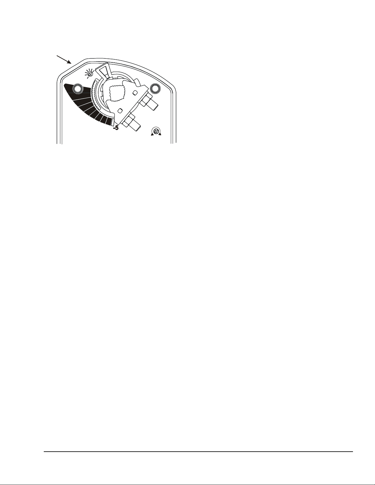
2. Rotate the switch adjuster until it points to the
Figure 14: Switch Trip Point Settings
FIG:M9208_ AGx_Adjust ments
90
85
50
30
40
60
70
desired switch point.
Switch AdjusterSwitch Adjuster
RA
DA
3. Connect Auxiliary Switch No. 2 to a power source
or an ohmmeter and apply power to the actuator.
The actuator moves to the fully open position and
holds while power is applied.
4. Observe the switch point. If required, repeat Step 1
through Step 3.
Repair Information
A number of replacement parts are available; see
Table 1 for more details. If an M9208-AGx-x Series
On/Off and Floating Point Control Electric Spring
Return Actuator fails to operate within its specifications,
replace the unit. For a replacement electric actuator,
contact the nearest Johnson Controls representative.
M9208-AGx-x Series On/Off and Floating Point Electric Spring Return Actuators Installation Instructions 9
Page 10

Technical Specifications
M9208-AGx-x Series On/Off and Floating Point Control Electric Spring Return Actuator (Part 1 of 2)
Power
Requirements
Input Signal -AGx Models AC 19.2 to 28.8 V at 50/60 Hz or DC 24 V +20%/-10%
Control Input
Impedance
Auxiliary Switch
Rating
Spring Return Direction Is Selectable with Mounting Position of Actuator:
Rated Torque Power On
Rotation Range Maximum Full Stroke: 95°
Rotation Time
for 90 Degrees of
Travel
Life Cycles 60,000 Full Stroke Cycles with 70 lb·in. (8 N·m) Load
Audible Noise
Rating
Electrical
Connections
Conduit Connections Integral Connectors for 3/8 in. (10 mm) Flexible Metal Conduit
Mechanical
Connections
Enclosure Rating NEMA 2 (IP54) for all Mounting Directions
-AGx Models AC 24 V (AC 19.2 V to 28.8 V) at 50/60 Hz: Class 2 (North America) or Safety
-AGx Models 3,000 ohm Control Inputs
-xxC Models Two Single-Pole, Double-Throw (SPDT), Double-Insulated Switches with Gold
(Running)
Power Off
(Spring Returning)
Power On
(Running)
Power Off
(Spring Returning)
Power On
(Running)
Power On
(Holding)
Power Off
(Spring Returning)
Models: AGx-3 48 in. (1.2 m) UL 758 Type AWM Halogen Free Cable with 18 AWG
Models: AGA-2 120 in. (3.05 m) UL 444 Type CMP Plenum Rated Cable with 19 AWG
Auxiliary Switches
(-xxC Models)
Round Shafts Range of Sizes: 5/16 to 5/8 in. (8 to 16 mm)
Square Shafts Range of Sizes: 1/4 to 1/2 in. (6 to 12 mm)
Extra-Low Voltage (SELV) (Europe), 7.9 VA Running, 5.5 VA Holding Position
DC 24 V (DC 21.6 V to 28.8 V): Class 2 (North America) or SELV (Europe),
3.5 W Running, 1.9 W Holding Position
Minimum Transformer Size: 8 VA per Actuator
Class 2 (North America) or SELV (Europe)
Minimum Pulse Width: 500 msec
over Silver Contacts:
AC 24 V, 50 VA Pilot Duty
AC 120 V, 5.8 A Resistive, 1/4 hp, 275 VA Pilot Duty
AC 240 V, 5.0 A Resistive, 1/4 hp, 275 VA Pilot Duty
Actuator Face Labeled A Is Away from Damper or Valve: CCW Spring Return
Actuator Face Labeled B Is Away from Damper or Valve: CW Spring Return
70 lb·in. (8 N·m) All Operating Temperatures
70 lb·in. (8 N·m) All Operating Temperatures
Adjustable Stop: 35 to 95° Maximum Position
150 Seconds Constant for 0 to 70 lb·in. (8·N m) Load,
at all Operating Conditions
17 to 25 Seconds for 0 to 70 lb·in. (8 N·m) Load, at Room Temperature
22 Seconds Nominal at Full Rated Load
94 Seconds Maximum with 70 lb·in. (8 N·m) Load, at -40°F (-40°C)
1,500,000 Repositions with 70 lb·in. (8 N·m) Load
<35 dBA at 70 lb·in. (8 N·m) Load, at a Distance of 39-13/32 in. (1 m)
<20 dBA at a Distance of 39-13/32 in. (1 m)
<52 dBA at 70 lb·in. (8 N·m) Load, at a Distance of 39-13/32 in. (1 m)
(0.85 mm²) Conductors and 0.25 in. (6 mm) Ferrule Ends
(0.75 mm²) Conductors and 0.25 in. (6 mm) Ferrule Ends
48 in. (1.2 m) UL 758 Type AWM Halogen Free Cable with 18 AWG
(0.85 mm²) Conductors and 0.25 in. (6 mm) Ferrule Ends
M9208-AGx-x Series On/Off and Floating Point Electric Spring Return Actuators Installation Instructions10
Page 11
Metasys® and Johnson Controls® are registered trademarks of Johnson Controls, Inc.
All other marks herein are the marks of their respective owners. © 2011 Johnson Controls, Inc.
Building Efficiency
507 E. Michigan Street, Milwaukee, WI 53202
M9208-AGx-x Series On/Off and Floating Point Control Electric Spring Return Actuator
(Part 2 of 2)
Ambient
Conditions
Dimensions 6.33 x 3.90 x 2.26 in. (160.7 x 99 x 57.5 mm)
Compliance United States UL Listed, CCN XAPX, File E27734; to UL 60730-1A: 2003-08, Ed. 3.1,
Shipping Weight Models: -AGA: 3.43 lb (1.6 kg)
The performance specifications are nominal (unless otherwise noted), and conform to accepted industry standards. For applications which
exceed these specifications, consult the local Johnson Controls office. Johnson Controls Inc. shall not be liable for damages resulting from
misapplication or misuse of its products.
Standard Operating -40 to 140°F (-40 to 60°C); 90% RH Maximum, Noncondensing
Storage -40 to 185ºF (-40 to 85ºC); 95% RH Maximum, Noncondensing
Automatic Electrical Controls for Household and Similar Use; and
UL 60730-2-14: 2002-02, Ed. 1, Part 2, Particular Requirements for Electric
Actuators. (Models: All)
Canada UL Listed, CCN XAPX7, File E27734; to UL 60730-1:02-CAN/CSA:
July 2002, 3rd Ed., Automatic Electrical Controls for Household and Similar
Use; and CSA C22.2 No. 24-93 Temperature Indicating and Regulating
Equipment (Models: All).
Europe CE Mark – Johnson Controls, Inc., declares that this product is in compliance
with the essential requirements and other relevant provisions of the
EMC Directive 2004/108/EC and Low Voltage Directive 2006/95/EC.
Australia and
New Zealand
C-Tick Mark, Australia/NZ Emissions Compliant (Models: All)
Models: -AGC: 3.8 lb (1.7 kg)
M9208-AGx-x Series On/Off and Floating Point Electric Spring Return Actuators Installation Instructions 11
Published in U.S.A. www.johnsoncontrols.com
 Loading...