

Page 1

LX Series Unit Ventilator Controller
User’s Guide
Code No. LIT-12011486
Issued June 22, 2009
Introduction . . . . . . . . . . . . . . . . . . . . . . . . . . . . . . . . . . . . . . . . . . . . . . . . . . . . . . . . . .9
Sensor Configuration Wizard . . . . . . . . . . . . . . . . . . . . . . . . . . . . . . . . . . . . . . . . . . . . . . 10
Control Features . . . . . . . . . . . . . . . . . . . . . . . . . . . . . . . . . . . . . . . . . . . . . . . . . . . . . . . . 10
LONMARK Functional Profile. . . . . . . . . . . . . . . . . . . . . . . . . . . . . . . . . . . . . . . . . . . . . 11
Units in LONWORKS Networks . . . . . . . . . . . . . . . . . . . . . . . . . . . . . . . . . . . . . . . . . . . . . . .14
Language Selection. . . . . . . . . . . . . . . . . . . . . . . . . . . . . . . . . . . . . . . . . . . . . . . . . . . . . . . 15
Selecting a Measurement System or Selecting a Language . . . . . . . . . . . . . . . . . . . . . 16
Unit Ventilator Controller Installation Overview. . . . . . . . . . . . . . . . . . . . . . . . . . . . 19
Inputs . . . . . . . . . . . . . . . . . . . . . . . . . . . . . . . . . . . . . . . . . . . . . . . . . . . . . . . . . . . . . . 19
10k Ohm or Digital Input . . . . . . . . . . . . . . . . . . . . . . . . . . . . . . . . . . . . . . . . . . . . . . . . . . 20
Analog Inputs. . . . . . . . . . . . . . . . . . . . . . . . . . . . . . . . . . . . . . . . . . . . . . . . . . . . . . . . . . . 21
4 to 20 mA Analog Input, Externally Supplied . . . . . . . . . . . . . . . . . . . . . . . . . . . . . . . . . . . 21
Sensors and Switches. . . . . . . . . . . . . . . . . . . . . . . . . . . . . . . . . . . . . . . . . . . . . . . . . . . . 22
Auxiliary Alarm Input . . . . . . . . . . . . . . . . . . . . . . . . . . . . . . . . . . . . . . . . . . . . . . . . . . . . . . 22
Bypass Contact Input. . . . . . . . . . . . . . . . . . . . . . . . . . . . . . . . . . . . . . . . . . . . . . . . . . . . . . 22
CO
Level Input . . . . . . . . . . . . . . . . . . . . . . . . . . . . . . . . . . . . . . . . . . . . . . . . . . . . . . . . . . 22
2
Discharge Temperature Input . . . . . . . . . . . . . . . . . . . . . . . . . . . . . . . . . . . . . . . . . . . . . . . 22
Economizer Enable Input. . . . . . . . . . . . . . . . . . . . . . . . . . . . . . . . . . . . . . . . . . . . . . . . . . . 22
Emergency Contact Input . . . . . . . . . . . . . . . . . . . . . . . . . . . . . . . . . . . . . . . . . . . . . . . . . . 22
Fan Speed Selector Input . . . . . . . . . . . . . . . . . . . . . . . . . . . . . . . . . . . . . . . . . . . . . . . . . . 22
Fan State Input . . . . . . . . . . . . . . . . . . . . . . . . . . . . . . . . . . . . . . . . . . . . . . . . . . . . . . . . . . 23
Mixed Air Temperature Input . . . . . . . . . . . . . . . . . . . . . . . . . . . . . . . . . . . . . . . . . . . . . . . . 23
Mode Selector . . . . . . . . . . . . . . . . . . . . . . . . . . . . . . . . . . . . . . . . . . . . . . . . . . . . . . . . . . . 23
Occupancy Input . . . . . . . . . . . . . . . . . . . . . . . . . . . . . . . . . . . . . . . . . . . . . . . . . . . . . . . . . 24
Outdoor Enthalpy Input . . . . . . . . . . . . . . . . . . . . . . . . . . . . . . . . . . . . . . . . . . . . . . . . . . . . 24
1LX Series Unit Ventilator Controller User’s Guide
Page 2

Outdoor Humidity Input . . . . . . . . . . . . . . . . . . . . . . . . . . . . . . . . . . . . . . . . . . . . . . . . . . . . 24
Outdoor Temperature Input . . . . . . . . . . . . . . . . . . . . . . . . . . . . . . . . . . . . . . . . . . . . . . . . . 24
Return Air Temperature Input . . . . . . . . . . . . . . . . . . . . . . . . . . . . . . . . . . . . . . . . . . . . . . . 24
Setpoint Offset Input . . . . . . . . . . . . . . . . . . . . . . . . . . . . . . . . . . . . . . . . . . . . . . . . . . . . . . 24
Space Enthalpy Input. . . . . . . . . . . . . . . . . . . . . . . . . . . . . . . . . . . . . . . . . . . . . . . . . . . . . . 25
Space Humidity Input . . . . . . . . . . . . . . . . . . . . . . . . . . . . . . . . . . . . . . . . . . . . . . . . . . . . . . 25
Space Temperature Input . . . . . . . . . . . . . . . . . . . . . . . . . . . . . . . . . . . . . . . . . . . . . . . . . . 25
Water Temperature Input. . . . . . . . . . . . . . . . . . . . . . . . . . . . . . . . . . . . . . . . . . . . . . . . . . . 25
Window Contact Input . . . . . . . . . . . . . . . . . . . . . . . . . . . . . . . . . . . . . . . . . . . . . . . . . . . . . 26
Outputs. . . . . . . . . . . . . . . . . . . . . . . . . . . . . . . . . . . . . . . . . . . . . . . . . . . . . . . . . . . . . 27
Analog Output . . . . . . . . . . . . . . . . . . . . . . . . . . . . . . . . . . . . . . . . . . . . . . . . . . . . . . . . . . 27
Analog Output Protection. . . . . . . . . . . . . . . . . . . . . . . . . . . . . . . . . . . . . . . . . . . . . . . . . . . 27
Digital Outputs. . . . . . . . . . . . . . . . . . . . . . . . . . . . . . . . . . . . . . . . . . . . . . . . . . . . . . . . . . 27
Staged Outputs . . . . . . . . . . . . . . . . . . . . . . . . . . . . . . . . . . . . . . . . . . . . . . . . . . . . . . . . . 29
Output Selections . . . . . . . . . . . . . . . . . . . . . . . . . . . . . . . . . . . . . . . . . . . . . . . . . . . . . . . 29
Fan Speed 1–3 . . . . . . . . . . . . . . . . . . . . . . . . . . . . . . . . . . . . . . . . . . . . . . . . . . . . . . . . . . 29
Heating Outputs 1–4 . . . . . . . . . . . . . . . . . . . . . . . . . . . . . . . . . . . . . . . . . . . . . . . . . . . . . . 29
Cooling Outputs 1–4 . . . . . . . . . . . . . . . . . . . . . . . . . . . . . . . . . . . . . . . . . . . . . . . . . . . . . . 29
Reversing Valve. . . . . . . . . . . . . . . . . . . . . . . . . . . . . . . . . . . . . . . . . . . . . . . . . . . . . . . . . . 29
Humidifier and Dehumidifier Outputs. . . . . . . . . . . . . . . . . . . . . . . . . . . . . . . . . . . . . . . . . . 30
Minimum Fresh Air Enable (MIN_FRESH_AIR_ENABLE) . . . . . . . . . . . . . . . . . . . . . . . . . 30
Economizer Enable . . . . . . . . . . . . . . . . . . . . . . . . . . . . . . . . . . . . . . . . . . . . . . . . . . . . . . . 30
Heat Valve ON-OFF. . . . . . . . . . . . . . . . . . . . . . . . . . . . . . . . . . . . . . . . . . . . . . . . . . . . . . . 30
Cool Valve ON-OFF. . . . . . . . . . . . . . . . . . . . . . . . . . . . . . . . . . . . . . . . . . . . . . . . . . . . . . . 30
Heat Cool Valve ON-OFF . . . . . . . . . . . . . . . . . . . . . . . . . . . . . . . . . . . . . . . . . . . . . . . . . . 30
Heat Valve Open or Close. . . . . . . . . . . . . . . . . . . . . . . . . . . . . . . . . . . . . . . . . . . . . . . . . . 30
Cooling Valve Open or Close. . . . . . . . . . . . . . . . . . . . . . . . . . . . . . . . . . . . . . . . . . . . . . . . 30
Heat Cool Valve Open or Close. . . . . . . . . . . . . . . . . . . . . . . . . . . . . . . . . . . . . . . . . . . . . . 30
Fan Speed Modulate (FAN_SPEED_MOD) . . . . . . . . . . . . . . . . . . . . . . . . . . . . . . . . . . . . 30
Heating Modulate (HEATING_MOD). . . . . . . . . . . . . . . . . . . . . . . . . . . . . . . . . . . . . . . . . . 31
LX Series Unit Ventilator Controller User’s Guide2
Page 3

Heating or Cooling Valve Modulate (HEATING_VALVE_MOD) (COOLING_VALVE_MOD)31
Fresh Air Damper Modulate (FRESH_AIR_DAMPER_MOD) . . . . . . . . . . . . . . . . . . . . . . . 31
Fresh Air Damper Open or Close . . . . . . . . . . . . . . . . . . . . . . . . . . . . . . . . . . . . . . . . . . . . 31
Mode Selection. . . . . . . . . . . . . . . . . . . . . . . . . . . . . . . . . . . . . . . . . . . . . . . . . . . . . . . 31
Network Variables Used for Mode Selection. . . . . . . . . . . . . . . . . . . . . . . . . . . . . . . . . . 31
Occupied Mode . . . . . . . . . . . . . . . . . . . . . . . . . . . . . . . . . . . . . . . . . . . . . . . . . . . . . . . . . 32
Starting Occupied Mode . . . . . . . . . . . . . . . . . . . . . . . . . . . . . . . . . . . . . . . . . . . . . . . . . . . 33
Ending Occupied Mode . . . . . . . . . . . . . . . . . . . . . . . . . . . . . . . . . . . . . . . . . . . . . . . . . . . . 33
Unoccupied Mode . . . . . . . . . . . . . . . . . . . . . . . . . . . . . . . . . . . . . . . . . . . . . . . . . . . . . . . 33
Starting Unoccupied Mode. . . . . . . . . . . . . . . . . . . . . . . . . . . . . . . . . . . . . . . . . . . . . . . . . . 33
Ending Unoccupied Mode . . . . . . . . . . . . . . . . . . . . . . . . . . . . . . . . . . . . . . . . . . . . . . . . . . 34
Bypass Mode . . . . . . . . . . . . . . . . . . . . . . . . . . . . . . . . . . . . . . . . . . . . . . . . . . . . . . . . . . . 34
Starting Bypass Mode . . . . . . . . . . . . . . . . . . . . . . . . . . . . . . . . . . . . . . . . . . . . . . . . . . . . . 35
Ending Bypass Mode. . . . . . . . . . . . . . . . . . . . . . . . . . . . . . . . . . . . . . . . . . . . . . . . . . . . . . 35
Standby Mode . . . . . . . . . . . . . . . . . . . . . . . . . . . . . . . . . . . . . . . . . . . . . . . . . . . . . . . . . . 35
Starting Standby Mode . . . . . . . . . . . . . . . . . . . . . . . . . . . . . . . . . . . . . . . . . . . . . . . . . . . . 35
Ending Standby Mode . . . . . . . . . . . . . . . . . . . . . . . . . . . . . . . . . . . . . . . . . . . . . . . . . . . . . 36
Slave Mode. . . . . . . . . . . . . . . . . . . . . . . . . . . . . . . . . . . . . . . . . . . . . . . . . . . . . . . . . . . . . 36
State Selection and Description. . . . . . . . . . . . . . . . . . . . . . . . . . . . . . . . . . . . . . . . . 36
Supervisory Control and Scheduling. . . . . . . . . . . . . . . . . . . . . . . . . . . . . . . . . . . . . . . . 36
Calculating the Space Temperature Setpoint . . . . . . . . . . . . . . . . . . . . . . . . . . . . . . . . . 37
The Effect of nviSetPoint on the Active Setpoints . . . . . . . . . . . . . . . . . . . . . . . . . . . . . . . . 37
The Effect of a Setpoint Offset on the Active Setpoints. . . . . . . . . . . . . . . . . . . . . . . . . . . . 38
Ventilation. . . . . . . . . . . . . . . . . . . . . . . . . . . . . . . . . . . . . . . . . . . . . . . . . . . . . . . . . . .38
Ventilation Separate from Free Cooling. . . . . . . . . . . . . . . . . . . . . . . . . . . . . . . . . . . . . . . . 38
Control of the Fresh Air Intake. . . . . . . . . . . . . . . . . . . . . . . . . . . . . . . . . . . . . . . . . . . . . . . 40
Outputs That Control the Fresh Air Damper . . . . . . . . . . . . . . . . . . . . . . . . . . . . . . . . . . . . 40
Humidity Control . . . . . . . . . . . . . . . . . . . . . . . . . . . . . . . . . . . . . . . . . . . . . . . . . . . . . . . . 41
Cooling State . . . . . . . . . . . . . . . . . . . . . . . . . . . . . . . . . . . . . . . . . . . . . . . . . . . . . . . . . . . 42
Free Cooling . . . . . . . . . . . . . . . . . . . . . . . . . . . . . . . . . . . . . . . . . . . . . . . . . . . . . . . . . . . . 42
LX Series Unit Ventilator Controller User’s Guide 3
Page 4

When Free Cooling is Used. . . . . . . . . . . . . . . . . . . . . . . . . . . . . . . . . . . . . . . . . . . . . . . . . 43
Mechanical Cooling . . . . . . . . . . . . . . . . . . . . . . . . . . . . . . . . . . . . . . . . . . . . . . . . . . . . . . . 43
Cooling Demand . . . . . . . . . . . . . . . . . . . . . . . . . . . . . . . . . . . . . . . . . . . . . . . . . . . . . . . . . 44
Cooling Output Sequence . . . . . . . . . . . . . . . . . . . . . . . . . . . . . . . . . . . . . . . . . . . . . . . . . . 44
Ending the Cooling State. . . . . . . . . . . . . . . . . . . . . . . . . . . . . . . . . . . . . . . . . . . . . . . . . . . 44
Heating States . . . . . . . . . . . . . . . . . . . . . . . . . . . . . . . . . . . . . . . . . . . . . . . . . . . . . . . . . . 45
Heating Demand . . . . . . . . . . . . . . . . . . . . . . . . . . . . . . . . . . . . . . . . . . . . . . . . . . . . . . . . . 46
Heating Output Sequence . . . . . . . . . . . . . . . . . . . . . . . . . . . . . . . . . . . . . . . . . . . . . . . . . . 46
Cooling Outputs Used to Heat. . . . . . . . . . . . . . . . . . . . . . . . . . . . . . . . . . . . . . . . . . . . . . . 46
Ending the Heating State. . . . . . . . . . . . . . . . . . . . . . . . . . . . . . . . . . . . . . . . . . . . . . . . . . . 46
Night Purge. . . . . . . . . . . . . . . . . . . . . . . . . . . . . . . . . . . . . . . . . . . . . . . . . . . . . . . . . . . . . 46
Morning Warm-up State . . . . . . . . . . . . . . . . . . . . . . . . . . . . . . . . . . . . . . . . . . . . . . . . . . 47
Using Night Purge and Morning Warm-up with DCV . . . . . . . . . . . . . . . . . . . . . . . . . . . 47
Fan Operation . . . . . . . . . . . . . . . . . . . . . . . . . . . . . . . . . . . . . . . . . . . . . . . . . . . . . . . 47
Terminal Load . . . . . . . . . . . . . . . . . . . . . . . . . . . . . . . . . . . . . . . . . . . . . . . . . . . . . . . 48
Heating Terminal Load . . . . . . . . . . . . . . . . . . . . . . . . . . . . . . . . . . . . . . . . . . . . . . . . . . . 49
Cooling Terminal Load . . . . . . . . . . . . . . . . . . . . . . . . . . . . . . . . . . . . . . . . . . . . . . . . . . . 50
Networking Operations. . . . . . . . . . . . . . . . . . . . . . . . . . . . . . . . . . . . . . . . . . . . . . . . 51
Slave Operation . . . . . . . . . . . . . . . . . . . . . . . . . . . . . . . . . . . . . . . . . . . . . . . . . . . . . . . . . 51
Load Shedding. . . . . . . . . . . . . . . . . . . . . . . . . . . . . . . . . . . . . . . . . . . . . . . . . . . . . . . . . . 51
Setting-up Network Connections. . . . . . . . . . . . . . . . . . . . . . . . . . . . . . . . . . . . . . . . . . . 51
Network Outputs . . . . . . . . . . . . . . . . . . . . . . . . . . . . . . . . . . . . . . . . . . . . . . . . . . . . . . . . . 52
Optimum Start . . . . . . . . . . . . . . . . . . . . . . . . . . . . . . . . . . . . . . . . . . . . . . . . . . . . . . . 53
Requirements for Optimum Start. . . . . . . . . . . . . . . . . . . . . . . . . . . . . . . . . . . . . . . . . . . 53
Emergency Operation. . . . . . . . . . . . . . . . . . . . . . . . . . . . . . . . . . . . . . . . . . . . . . . . . 54
Emergency Initiation . . . . . . . . . . . . . . . . . . . . . . . . . . . . . . . . . . . . . . . . . . . . . . . . . . . . . 55
Normal Operation. . . . . . . . . . . . . . . . . . . . . . . . . . . . . . . . . . . . . . . . . . . . . . . . . . . . . . . . . 55
The PID Loop. . . . . . . . . . . . . . . . . . . . . . . . . . . . . . . . . . . . . . . . . . . . . . . . . . . . . . . . 55
Proportional . . . . . . . . . . . . . . . . . . . . . . . . . . . . . . . . . . . . . . . . . . . . . . . . . . . . . . . . . . . . 56
Integral . . . . . . . . . . . . . . . . . . . . . . . . . . . . . . . . . . . . . . . . . . . . . . . . . . . . . . . . . . . . . . . . 56
LX Series Unit Ventilator Controller User’s Guide4
Page 5

Gain . . . . . . . . . . . . . . . . . . . . . . . . . . . . . . . . . . . . . . . . . . . . . . . . . . . . . . . . . . . . . . . . . . . 57
Time. . . . . . . . . . . . . . . . . . . . . . . . . . . . . . . . . . . . . . . . . . . . . . . . . . . . . . . . . . . . . . . . . . . 57
How It Is Used . . . . . . . . . . . . . . . . . . . . . . . . . . . . . . . . . . . . . . . . . . . . . . . . . . . . . . . . . . . 57
Derivative . . . . . . . . . . . . . . . . . . . . . . . . . . . . . . . . . . . . . . . . . . . . . . . . . . . . . . . . . . . . . . 58
Gain . . . . . . . . . . . . . . . . . . . . . . . . . . . . . . . . . . . . . . . . . . . . . . . . . . . . . . . . . . . . . . . . . . . 58
Time. . . . . . . . . . . . . . . . . . . . . . . . . . . . . . . . . . . . . . . . . . . . . . . . . . . . . . . . . . . . . . . . . . . 59
Deadband . . . . . . . . . . . . . . . . . . . . . . . . . . . . . . . . . . . . . . . . . . . . . . . . . . . . . . . . . . . . . . 59
Alarm Operation. . . . . . . . . . . . . . . . . . . . . . . . . . . . . . . . . . . . . . . . . . . . . . . . . . . . . . 60
Alarm Features. . . . . . . . . . . . . . . . . . . . . . . . . . . . . . . . . . . . . . . . . . . . . . . . . . . . . . . . . . 61
Alarm Types . . . . . . . . . . . . . . . . . . . . . . . . . . . . . . . . . . . . . . . . . . . . . . . . . . . . . . . . . . . . 62
Alarm Procedure . . . . . . . . . . . . . . . . . . . . . . . . . . . . . . . . . . . . . . . . . . . . . . . . . . . . . . . . 62
Heartbeat Alarms. . . . . . . . . . . . . . . . . . . . . . . . . . . . . . . . . . . . . . . . . . . . . . . . . . . . . . . . . 63
Disconnect Alarms. . . . . . . . . . . . . . . . . . . . . . . . . . . . . . . . . . . . . . . . . . . . . . . . . . . . . . . . 65
Emergency Mode Alarms. . . . . . . . . . . . . . . . . . . . . . . . . . . . . . . . . . . . . . . . . . . . . . . . . . . 65
User-Set Alarms. . . . . . . . . . . . . . . . . . . . . . . . . . . . . . . . . . . . . . . . . . . . . . . . . . . . . . . . . . 65
Setting up the Unit Ventilator Controller. . . . . . . . . . . . . . . . . . . . . . . . . . . . . . . . . . 66
Persistent Network Variables . . . . . . . . . . . . . . . . . . . . . . . . . . . . . . . . . . . . . . . . . . . . . . 66
Setting Units. . . . . . . . . . . . . . . . . . . . . . . . . . . . . . . . . . . . . . . . . . . . . . . . . . . . . . . . . . . . 67
Input Configuration . . . . . . . . . . . . . . . . . . . . . . . . . . . . . . . . . . . . . . . . . . . . . . . . . . . 67
Output Configuration. . . . . . . . . . . . . . . . . . . . . . . . . . . . . . . . . . . . . . . . . . . . . . . . . . 68
Output Signal Types . . . . . . . . . . . . . . . . . . . . . . . . . . . . . . . . . . . . . . . . . . . . . . . . . . . . . 69
Configuring an Output. . . . . . . . . . . . . . . . . . . . . . . . . . . . . . . . . . . . . . . . . . . . . . . . . . . . 69
Configuring an Output Represented as a Functional Block. . . . . . . . . . . . . . . . . . . . . . . . . 71
Heating-Cooling Configuration. . . . . . . . . . . . . . . . . . . . . . . . . . . . . . . . . . . . . . . . . . 72
Optimum Start . . . . . . . . . . . . . . . . . . . . . . . . . . . . . . . . . . . . . . . . . . . . . . . . . . . . . . . . . . 73
Fan-Valve Configuration . . . . . . . . . . . . . . . . . . . . . . . . . . . . . . . . . . . . . . . . . . . . . . . 74
PID Configuration . . . . . . . . . . . . . . . . . . . . . . . . . . . . . . . . . . . . . . . . . . . . . . . . . . . . 76
Alarm Configuration . . . . . . . . . . . . . . . . . . . . . . . . . . . . . . . . . . . . . . . . . . . . . . . . . . 77
Space and Return Temperatures and Humidity . . . . . . . . . . . . . . . . . . . . . . . . . . . . . . . 77
Levels . . . . . . . . . . . . . . . . . . . . . . . . . . . . . . . . . . . . . . . . . . . . . . . . . . . . . . . . . . . . . 78
CO
2
LX Series Unit Ventilator Controller User’s Guide 5
Page 6

Discharge Temperature and Auxiliary Alarm . . . . . . . . . . . . . . . . . . . . . . . . . . . . . . . . . 78
Mixed Air Temperature . . . . . . . . . . . . . . . . . . . . . . . . . . . . . . . . . . . . . . . . . . . . . . . . . . . 78
Fan Alarm . . . . . . . . . . . . . . . . . . . . . . . . . . . . . . . . . . . . . . . . . . . . . . . . . . . . . . . . . . . . . . 78
General Settings Configuration. . . . . . . . . . . . . . . . . . . . . . . . . . . . . . . . . . . . . . . . . 79
Radiation Heating . . . . . . . . . . . . . . . . . . . . . . . . . . . . . . . . . . . . . . . . . . . . . . . . . . . . . . . 80
Options Configuration . . . . . . . . . . . . . . . . . . . . . . . . . . . . . . . . . . . . . . . . . . . . . . . . 81
Optimum Start . . . . . . . . . . . . . . . . . . . . . . . . . . . . . . . . . . . . . . . . . . . . . . . . . . . . . . . . . . 81
Frost Protection. . . . . . . . . . . . . . . . . . . . . . . . . . . . . . . . . . . . . . . . . . . . . . . . . . . . . . . . . 82
Humidity Control . . . . . . . . . . . . . . . . . . . . . . . . . . . . . . . . . . . . . . . . . . . . . . . . . . . . . . . . 82
Network Input Configuration . . . . . . . . . . . . . . . . . . . . . . . . . . . . . . . . . . . . . . . . . . . 83
Heartbeat Alarms. . . . . . . . . . . . . . . . . . . . . . . . . . . . . . . . . . . . . . . . . . . . . . . . . . . . . . . . 83
Network Output Configuration. . . . . . . . . . . . . . . . . . . . . . . . . . . . . . . . . . . . . . . . . . 84
Object Manage. . . . . . . . . . . . . . . . . . . . . . . . . . . . . . . . . . . . . . . . . . . . . . . . . . . . . . . 85
Object Status . . . . . . . . . . . . . . . . . . . . . . . . . . . . . . . . . . . . . . . . . . . . . . . . . . . . . . . . . . . 85
Communication Failure . . . . . . . . . . . . . . . . . . . . . . . . . . . . . . . . . . . . . . . . . . . . . . . . . . . . 87
Electrical Fault . . . . . . . . . . . . . . . . . . . . . . . . . . . . . . . . . . . . . . . . . . . . . . . . . . . . . . . . . . . 87
Out of Limits. . . . . . . . . . . . . . . . . . . . . . . . . . . . . . . . . . . . . . . . . . . . . . . . . . . . . . . . . . . . . 87
Disabled. . . . . . . . . . . . . . . . . . . . . . . . . . . . . . . . . . . . . . . . . . . . . . . . . . . . . . . . . . . . . . . . 87
In Alarm . . . . . . . . . . . . . . . . . . . . . . . . . . . . . . . . . . . . . . . . . . . . . . . . . . . . . . . . . . . . . . . . 87
In Override. . . . . . . . . . . . . . . . . . . . . . . . . . . . . . . . . . . . . . . . . . . . . . . . . . . . . . . . . . . . . . 87
Out of Service . . . . . . . . . . . . . . . . . . . . . . . . . . . . . . . . . . . . . . . . . . . . . . . . . . . . . . . . . . . 87
Network Variables. . . . . . . . . . . . . . . . . . . . . . . . . . . . . . . . . . . . . . . . . . . . . . . . . . . . 87
nviApplicMode . . . . . . . . . . . . . . . . . . . . . . . . . . . . . . . . . . . . . . . . . . . . . . . . . . . . . . . . . . 88
nviCO2 . . . . . . . . . . . . . . . . . . . . . . . . . . . . . . . . . . . . . . . . . . . . . . . . . . . . . . . . . . . . . . . . 88
nviDischargeTemp. . . . . . . . . . . . . . . . . . . . . . . . . . . . . . . . . . . . . . . . . . . . . . . . . . . . . . . 88
nviEconoEnable. . . . . . . . . . . . . . . . . . . . . . . . . . . . . . . . . . . . . . . . . . . . . . . . . . . . . . . . . 88
nviEmergCmd. . . . . . . . . . . . . . . . . . . . . . . . . . . . . . . . . . . . . . . . . . . . . . . . . . . . . . . . . . . 89
nviExtCmdOutputx . . . . . . . . . . . . . . . . . . . . . . . . . . . . . . . . . . . . . . . . . . . . . . . . . . . . . . 89
nviFanSpeedCmd. . . . . . . . . . . . . . . . . . . . . . . . . . . . . . . . . . . . . . . . . . . . . . . . . . . . . . . . 89
nviFanState. . . . . . . . . . . . . . . . . . . . . . . . . . . . . . . . . . . . . . . . . . . . . . . . . . . . . . . . . . . . . 89
LX Series Unit Ventilator Controller User’s Guide6
Page 7

nviHotWater . . . . . . . . . . . . . . . . . . . . . . . . . . . . . . . . . . . . . . . . . . . . . . . . . . . . . . . . . . . . 90
nviMixedAirTemp. . . . . . . . . . . . . . . . . . . . . . . . . . . . . . . . . . . . . . . . . . . . . . . . . . . . . . . . 90
nviOccCmd and nviOccManCmd . . . . . . . . . . . . . . . . . . . . . . . . . . . . . . . . . . . . . . . . . . . 90
nviOutdoorEnth . . . . . . . . . . . . . . . . . . . . . . . . . . . . . . . . . . . . . . . . . . . . . . . . . . . . . . . . . 90
nviOutdoorRH . . . . . . . . . . . . . . . . . . . . . . . . . . . . . . . . . . . . . . . . . . . . . . . . . . . . . . . . . . 90
nviOutdoorTemp . . . . . . . . . . . . . . . . . . . . . . . . . . . . . . . . . . . . . . . . . . . . . . . . . . . . . . . . 91
nviReturnTemp. . . . . . . . . . . . . . . . . . . . . . . . . . . . . . . . . . . . . . . . . . . . . . . . . . . . . . . . . . 91
nviSetPoint. . . . . . . . . . . . . . . . . . . . . . . . . . . . . . . . . . . . . . . . . . . . . . . . . . . . . . . . . . . . . 91
nviSetPointOffset. . . . . . . . . . . . . . . . . . . . . . . . . . . . . . . . . . . . . . . . . . . . . . . . . . . . . . . . 91
nviShedding . . . . . . . . . . . . . . . . . . . . . . . . . . . . . . . . . . . . . . . . . . . . . . . . . . . . . . . . . . . . 91
nviSlave . . . . . . . . . . . . . . . . . . . . . . . . . . . . . . . . . . . . . . . . . . . . . . . . . . . . . . . . . . . . . . . 91
nviSpaceEnth. . . . . . . . . . . . . . . . . . . . . . . . . . . . . . . . . . . . . . . . . . . . . . . . . . . . . . . . . . . 91
nviSpaceRH . . . . . . . . . . . . . . . . . . . . . . . . . . . . . . . . . . . . . . . . . . . . . . . . . . . . . . . . . . . . 92
nviSpaceTemp . . . . . . . . . . . . . . . . . . . . . . . . . . . . . . . . . . . . . . . . . . . . . . . . . . . . . . . . . . 92
nviWaterTemp . . . . . . . . . . . . . . . . . . . . . . . . . . . . . . . . . . . . . . . . . . . . . . . . . . . . . . . . . . 92
nvoCtrlOutputx. . . . . . . . . . . . . . . . . . . . . . . . . . . . . . . . . . . . . . . . . . . . . . . . . . . . . . . . . . 92
nvoDischargeSetPt . . . . . . . . . . . . . . . . . . . . . . . . . . . . . . . . . . . . . . . . . . . . . . . . . . . . . . 92
nvoEconoEnable . . . . . . . . . . . . . . . . . . . . . . . . . . . . . . . . . . . . . . . . . . . . . . . . . . . . . . . . 92
nvoEffectSetPt . . . . . . . . . . . . . . . . . . . . . . . . . . . . . . . . . . . . . . . . . . . . . . . . . . . . . . . . . . 92
nvoFanSpeed . . . . . . . . . . . . . . . . . . . . . . . . . . . . . . . . . . . . . . . . . . . . . . . . . . . . . . . . . . . 93
nvoHwInputx . . . . . . . . . . . . . . . . . . . . . . . . . . . . . . . . . . . . . . . . . . . . . . . . . . . . . . . . . . . 93
nvoOccState. . . . . . . . . . . . . . . . . . . . . . . . . . . . . . . . . . . . . . . . . . . . . . . . . . . . . . . . . . . . 93
nvoUValarm. . . . . . . . . . . . . . . . . . . . . . . . . . . . . . . . . . . . . . . . . . . . . . . . . . . . . . . . . . . . 93
nvoUVstate. . . . . . . . . . . . . . . . . . . . . . . . . . . . . . . . . . . . . . . . . . . . . . . . . . . . . . . . . . . . . 95
nvoSpaceTemp . . . . . . . . . . . . . . . . . . . . . . . . . . . . . . . . . . . . . . . . . . . . . . . . . . . . . . . . . 96
nvoTerminalLoad. . . . . . . . . . . . . . . . . . . . . . . . . . . . . . . . . . . . . . . . . . . . . . . . . . . . . . . . 97
nvoUnitStatus. . . . . . . . . . . . . . . . . . . . . . . . . . . . . . . . . . . . . . . . . . . . . . . . . . . . . . . . . . . 97
Standard Network Variable Types (SNVTs). . . . . . . . . . . . . . . . . . . . . . . . . . . . . . . . 98
SNVT_hvac_emerg (103). . . . . . . . . . . . . . . . . . . . . . . . . . . . . . . . . . . . . . . . . . . . . . . . . . 98
SNVT_hvac_mode (108) . . . . . . . . . . . . . . . . . . . . . . . . . . . . . . . . . . . . . . . . . . . . . . . . . . 98
LX Series Unit Ventilator Controller User’s Guide 7
Page 8

SNVT_hvac_status (112). . . . . . . . . . . . . . . . . . . . . . . . . . . . . . . . . . . . . . . . . . . . . . . . . . 99
Alarm State. . . . . . . . . . . . . . . . . . . . . . . . . . . . . . . . . . . . . . . . . . . . . . . . . . . . . . . . . . . . 102
SNVT_lev_percent (81) . . . . . . . . . . . . . . . . . . . . . . . . . . . . . . . . . . . . . . . . . . . . . . . . . . 103
SNVT_occupancy (109) . . . . . . . . . . . . . . . . . . . . . . . . . . . . . . . . . . . . . . . . . . . . . . . . . 103
SNVT_ppm (29) . . . . . . . . . . . . . . . . . . . . . . . . . . . . . . . . . . . . . . . . . . . . . . . . . . . . . . . . 104
SNVT_switch (95). . . . . . . . . . . . . . . . . . . . . . . . . . . . . . . . . . . . . . . . . . . . . . . . . . . . . . . 104
Switch Definition . . . . . . . . . . . . . . . . . . . . . . . . . . . . . . . . . . . . . . . . . . . . . . . . . . . . . . . . 104
SNVT_temp_p (105) . . . . . . . . . . . . . . . . . . . . . . . . . . . . . . . . . . . . . . . . . . . . . . . . . . . . 106
SNVT_tod_event (128) . . . . . . . . . . . . . . . . . . . . . . . . . . . . . . . . . . . . . . . . . . . . . . . . 106
LX Series Unit Ventilator Controller User’s Guide8
Page 9

LX Series Unit Ventilator Controller
User's Guide
Introduction
The LX Series Unit Ventilator Controller (UVC) seamlessly integrates into a
LONWORKS® network for the control of almost any Unit Ventilator Controller due
to its wide range of output types and LONMARK® certification.
The LX Series Unit Ventilator Controller controls the following equipment:
• up to four stages of mechanical heating or cooling
• modulating heating or cooling valves
• reversing valves for application requiring a heat pump
• floating valves for heating or cooling
• unit ventilator with or without an economizer
• up to three fan speeds or variable speed fans
• humidifier and dehumidifier
• an economizer that requires analog, digital, or Pulse Width Modulation (PWM)
control signals
The UVC has five digital outputs supplying 1.0 ampere at 24 VAC. These outputs
produce digital or PWM signals.
There are also two tri-mode analog outputs on the circuit board. These outputs
provide the following signals:
• linear signals over a 0 to 10 VDC range
• 10 VDC digital or PWM signals
• digital signals of 60 mA at 12 VDC
The controller has six inputs, each capable of one of 21 possible input types. Inputs
have 12-bit resolution and are configured completely by software.
For easy maintenance and installation, the controller is equipped with plug-in
connectors that accept flat cable or wires. The controller uses a TP/FT-10 78 kbps
network configuration.
The information in this guide helps you to set up the UVC, understand the
operation of the UVC, and troubleshoot problems of the device. Information is
organized to follow the UVC configuration wizard menu.
LX Series Unit Ventilator Controller User's Guide 9
Page 10

Sensor Configuration Wizard
The UVC incorporates the sensor configuration wizard. The wizard provides
powerful and simple configuration tools for the hardware inputs. You can select
the digital or analog inputs through the software, which means there are no circuit
board jumpers to move.
Analog input signal types - resistive, voltage, current - are selected in software
without hardware jumpers. Built-in conversion tables are provided for a large
number of thermistors or other sensor types. You can easily create custom
conversion tables by setting the offset, minimum, and maximum values in one
dialog box for the input.
The sensor configuration wizard also provides direct access to network properties
of the analog or digital input including the Standard Network Variable Type
(SNVT), Heartbeat, Send on Delta, Override, Default Value, and Throttle settings.
All input features are conveniently located on one screen, which avoids the hassle
of switching back and forth between screens to fully configure an input. In
addition, the wizard provides warnings of configuration errors as they occur,
enabling you to correct mistakes quickly.
Shown by the LX-UVL wizard view in FX Workbench, the sensor configuration
wizard exists as a separate object. A separate functional block represents each
hardware input. To configure an input, select the hardware input on the left side of
the LX-UVL wizard view of the device and click the Launch button. The sensor
configuration wizard allows you to control network inputs not directly controlled
by the Unit Ventilator Controller.
Control Features
The Unit Ventilator Controller provides Proportional plus Integral plus Derivative
(PID) loops for advanced control of humidity, discharge temperature, and space
temperature. Each PID loop has an individual, configurable deadpan. In addition,
each PID loop provides gain and time adjustment for the integral and derivative
terms, and gain adjustment for the proportional term.
Whereas space temperature control is done with a PI loop only , the presence of the
derivative term adds the ability to precisely adjust space temperature control to
provide better comfort and increased savings.
The PID loop is especially useful in controlling the CO2 concentration, since this
can vary quickly and greatly as individuals enter and exit meeting rooms, and work
areas. The quick response of the PID loop also maintains duct pressure within
acceptable limits.
Humidification and dehumidification sequences provide the UVC with the ability
to maintain the space humidity at the desired level. The Unit Ventilator Controller
also provides advanced control features often associated with air handlers. These
features include Optimum Start and load shedding.
LX Series Unit Ventilator Controller User's Guide10
Page 11

The Optimum Start function maintains statistics that enable the Unit Ventilator
Controller to predict the warm-up or cool-down time period needed to make the
building ready for occupancy. The precise Optimum Start period is calculated
every day using the current outdoor air temperature.
LONMARK Functional Profile
The LX Series Unit Ventilator Controller uses LONWORKS network protocol and is
LONMARK certified for interoperability on any LONWORKS network. The Unit
Ventilator Controller is set up through its own configuration wizard and the Sensor
configuration wizard. You can use FX Workbench or any other network
management tool to install the device onto the network and bind variable
connections.
Figure 1 shows that the Unit Ventilator Controller meets the LONMARK standard
by providing the network variable inputs, network variable outputs, and
configuration properties specified by the profile. In addition, the Unit Ventilator
Controller provides many extra network variable inputs and outputs. These extra
network variables provide a greater flexibility and number of functions than
required in the LONMARK profile.
For example, you can use network input nviSlave, to slave the UVC to another
unit, whereas network output nvoUnitStatus, enables the UVC to act as the master
node. The Unit Ventilator Controller has network inputs that permit the use of
outside enthalpy sensors and space enthalpy sensors. These inputs provide better
calculation of the cooling or heating effect of the outside air upon the conditioned
space.
The input object has conversion tables and hardware properties present as
configuration properties in the area marked Manufacturer Configuration
Properties. By choosing from a list of standard thermistors, you can select different
conversion properties. The conversion tables configuration property allows you to
create your own custom tables. Hardware properties, located in the same area,
allow you to modify your input from the software object.
LX Series Unit Ventilator Controller User's Guide 11
Page 12

nviSpaceTemp
SNVT_ temp_p
nviApplicMode
SNVT_ hvac_ mode
nviSetP tOffset
SNVT_ temp_p
nviOutdoorTem p
SNVT_ temp_p
nviOutdoorR H
SNVT_lev_ percent
nviSpaceRH
SNV T_ lev_ percent
nviCO2
SNVT_ ppm
nviEmergCmd
SNV T_ hvac_ emerg
Occ. Temperature Set Points (mandatory)
nviEconoEnable
SNVT_ switch
nviFanState
SNVT_ switch
nviFanSpeedCmd
SNVT_ switch
nv iM ixed A ir Te m p
SNVT_ temp_p
nviOccManCmd
SNVT_ occupancy
nviReturnTemp
SNVT_ temp_p
nviShedding
SNVT_ switch
nviS lav e
SNVT_ hvac_ status
nviSupplyTem p
SNVT_ temp_p
nviOccCm d
SNV T_ tod_event
nviSpaceEnth
SNV T_ enthalpy
nviOutdoorE nth
SNVT_ enthalpy
nviWaterTemp
SNVT_ temp_p
nviHotWater
SNVT_ switch
nviSetpoint
SNVT_ temp_p
Manufacturer Configuration Properties
LX-UVL- 1 Unit Ventilator
Object Type # 808 0
Mandatory
Netw ork
Variables
Optional
Netw ork
Variables
C o n fig ura t io n P r o p e r tie s
Maximum S end Time (mandatory)
Minimum Send Time (optional)
Maximum R eceive Time ( optional)
CO 2 limit (optional)
Local Bypass Time (optional)
Manufacturer
Netw ork
Variables
Please see the m anual for details.
Wizard for configuration provided.
nvoSpaceTemp
SNVT_ temp_p
nv oU n itSta tu s
SNVT_ hvac_ status
nv oE ffe c tS e tp t
SNVT_ temp_p
nvoEconoEnable
SNVT_ switch
nvoFanSpeed
SNVT_ switch
nv oO ccS ta te
SNVT_ occupancy
nvoTerminalLoad
SNV T_ lev_ percent
nvoCtrlO utput1
SNVT_ switch
.
.
.
nvoCtrlO utput7
SNVT_ switch
nvoSupplySetPt
SNVT_ temp_p
Figure 1: LX Series Unit Ventilator Controller:
L
ONMARK Functional Profile
LX Series Unit Ventilator Controller User's Guide12
Page 13

Figure 2 shows the Unit Ventilator Controller input object and the output object.
6 x LX-UVL-1 Hardware Input
Object Type #1
Mandatory
Network
Variables
Configuration Properties
Offset ( optional)
Maximum Range (optional)
Minimum Range (optional)
Minimum Send Delta (optional)
Maximum Send Time (optional)
Minimum Send Time (optional)
Override Value (optional)
Manufacturer Configuration Properties
Object M ajo r Ve rsion
Object Minor Version
Input Signal Conditioning
Hardware Properties
Translation Table
Default Value
nvoHwInput1
SNVT _xxx
nviExtCmdOutput1
SNVT _switch
Figure 2: LX Series Unit Ventilator Controller Inputs and Outputs
7 x LX-UVL-1 Hardware Output
Object Type #3
Mandatory
Network
Variables
Configuration Properties
Maximum Receive Time ( optional)
Override Value (optional)
Manufacturer Configuration Properties
Ob je c t Major Ve rsion
Ob je c t Minor Ve rsion
Output Signal Conditioning
PWM Period
Hardware Properties
Default Value
LX Series Unit Ventilator Controller User's Guide 13
Page 14

The node object displays the nvoUVstate and nvoUValarm variables as
manufacturer’s variables. These variables provide information about the alarm
conditions in the Unit Ventilator Controller and about the operating state of the
device (Figure 3).
LX-UVL - 1 Node
Object Type #0
nviRequest
SNVT _obj_request
Mandatory
Network
Variables
Optional
Network
Variables
Configuration Properties
Location (optional)
Device Major Version (optional)
Device Minor Version (optional)
Manufacturer
Network
Variables
nvoStatus
SNVT _obj_ status
nvoFileDirectory
SNVT _ address
nvoUVstate
SNVT _state_64
nvoUValarm
SNVT _state_64
Manufacturer Configuration Properties
Maximum Send Time
Figure 3: LX Series Unit Ventilator Controller
Node Object Type
Units in LONWORKS Networks
Note: Use this section if you are using the Imperial System of measure.
The Imperial System and the International System (SI) are the two main
measurement systems used today. Table 1 compares Imperial units and SI units.
Table 1: Comparing Imperial and SI Units
Imperial Units SI
inch centimeter
yard meter
mile kilometer
degrees Fahrenheit degrees Centigrade
Echelon® SNVTs are based upon SI units. Thus, the most basic structure of the
ONWORKS network is SI based. This basis can lead to some unavoidable
L
problems in data conversion if you are using Imperial units.
LX Series Unit Ventilator Controller User's Guide14
Page 15

The LX-UVL wizard in FX Workbench provides some automatic conversion
between SI and Imperial units. However, these are not ideal conversions because a
whole number in one system becomes a long decimal fraction in the other. For
example, 72°F is approximately equal to 22.22222°C.
Value is written in
Imperial Units.
Data is displayed
for monitoring in
Imperial Units.
Value is translated
to SI units.
Value is rounded.
Value is stored
in SNVT.
Value is read
from SNVT.
Value is rounded.
Value is translated
to SI units.
Units
Figure 4: Writing and Reading Data in Imperial Units in the
ONWORKS Network
L
The values created by converting Imperial to SI or SI to Imperial are subject to
rounding errors. If you enter an Imperial value into a LONWORKS SNVT by using
the LX-UVL Controller configuration wizard, the value is converted after it is
entered, then rounded and written to the SNVT. When you want to monitor the
SNVT, the value must be read from the SNVT, converted, and rounded again
before it is displayed. Due to the two conversions and two rounding operations, the
value may differ slightly from what you originally entered (Figure 4).
The same process and resulting rounding error applies to Standard Configuration
Property Types (SCPTs).
Instructions for changing or modifying the units of measure used on your computer
are provided in the Selecting a Measurement System or Selecting a Language
section.
Language Selection
The following may require you to change your language settings:
• You changed your regional settings by selecting a different region in the
Regional and Language Options dialog box.
• You are working on a site that is in a linguistic region other than your own.
• You are dissatisfied with the language displayed on program menus and dialog
boxes.
LX Series Unit Ventilator Controller User's Guide 15
Page 16

You can change your language settings in the Advanced tab of the Regional and
Language Options dialog box. Instructions are provided in the following Selecting
a Measurement System or Selecting a Language section.
Selecting a Measurement System or Selecting a Language
To select units of measurement or to select a language:
1. In Microsoft® Windows XP® operating system, click Start > Control Panel.
The Control Panel appears.
2. In the Control Panel, open Date, Time, Language, and Regional Options.
3. Under the list titled Pick a Task, select and open the second item titled Change
the format of numbers, dates, and times (Figure 5).
Figure 5: Date, Time, Language, and Regional Options Screen
LX Series Unit Ventilator Controller User's Guide16
Page 17

4. Select your language region from the drop-down list provided. The number,
time, and date formats fill automatically (Figure 6).
Figure 6: Regional and Language Options Dialog Box
5. In the Number box, verify the number format uses a decimal point to indicate
numerals representing values less than 1. For example, use 123,456,789.00,
not 123 456 789,00. You must use a decimal point for the correct display of
numerals.
6. In the Regional Options dialog box, click Customize.
LX Series Unit Ventilator Controller User's Guide 17
Page 18

7. Click on the drop-down arrow next to the box labeled Measurement system
and select Metric (Figure 7).
Figure 7: Customize Regional Options
8. Verify the Decimal symbol box contains a decimal symbol. If the Decimal
symbol box does not contain a decimal symbol, select the symbol in the box,
and click Apply.
9. Click OK.
10. Click the Advanced tab and choose a language region by selecting from the
drop-down list. Verify the correct language appears on program menus.
11. Click OK.
You have now set the units to appear in the LX-UVL wizard. If you have chosen to
display Imperial units, remember that the SNVTs are still using SI units. If you are
viewing the data in Imperial units, you are viewing a converted, rounded value.
LX Series Unit Ventilator Controller User's Guide18
Page 19

Unit Ventilator Controller Installation Overview
Figure 8 shows one possible installation of the Unit Ventilator Controller. Inputs,
outputs, ducts, and heating or cooling units have been marked for your
convenience.
Note: Not all possible sensors are shown.
LX-UVL- 1 Installation Overview
Unit Ventilator Enclosure
Damper
Intake A ir
Filter
OAH
Fresh Air
(Economizer)
Damper
Damper
Unit Ventilator Enclosure
Mixed
Air
C
O
3 Fan
Speeds
Return
MAT DATOAT
Air
RAT
Heating
Coolin g
Unit Ventilator Enclosure
Humidifier
Discharge
Air
Sensor Symbols
Humidity
Temperature
Carbon Dioxide
Digital Input
Humidity
Temperature
Setpoint Offsett
MAT Mixed Air Temperature
C
O
OAH Outside Air Humidity
OAT Outside Air Temperature
Occupancy
Conditioned Space
RAT Return Air Temperature
DAT Discharge Air Temperature
Figure 8: Possible LX-UVL Installation
Inputs
The Unit Ventilator Controller has six universal inputs. You can configure
universal inputs by using the Unit Ventilator Controller configuration wizard.
Universal inputs are configured as either:
• analog inputs sensing either current or voltage, or
• digital inputs or 10k ohm resistance inputs
Note: Because the Unit Ventilator Controller can connect to a maximum of six
sensors, you may want to connect some sensors using the LONWORKS
network. All valid network inputs have priority over hardware inputs.
LX Series Unit Ventilator Controller User's Guide 19
Page 20

10k Ohm or Digital Input
The universal input, when configured as a 10k ohm or digital input, accepts a 10k
ohm resistance input or a digital input such as a switch, also known as a cold
contact.
The 10k ohm resistance range accommodates 10k ohm thermistors used in space
temperature sensors or duct temperature sensors, or a 10k ohm potentiometer used
as a setpoint offset.
Use the conversion table for resistance input of more than 10k ohm. The digital
range accommodates the occupancy contact, bypass switch, and window switch.
See Figure 9 for wiring information for both 10k ohm resistance and digital inputs.
LX-UVL
1
I
+
Both inputs are configured as 10 k Ohm
or Digital Input Configuration could be done
with either the LX -UVL wizard in or the
Hardware Input Wizard
Figure 9: 10k Ohm or Digital Input
3
I2I
–
++ + + +
I4 I6I5
––
Thermistor
10kO hm
Contact
NO -NC
LX Series Unit Ventilator Controller User's Guide20
Page 21

Analog Inputs
Analog inputs include current inputs with a range of 4 – 20 mA, and voltage inputs
with a range of 0 – 10 VDC.
4 to 20 mA Analog Input, Externally Supplied
Current inputs require a power supply either on the sensor or wired in series with
the sensor. To construct the current input, a 500-ohm 0.25-watt resistor is placed
across the Unit Ventilator Controller’s input terminals. See Figure 10 and
Figure 11.
LX--UVL
1
I
–
++++++
I2I
3
4
I
I
5
––
6
I
1
8
0
Resistor:
500
Ω −
Watt
Internal 24
powersupply
¼
VDC
4–20mA
–
+
Controller source
output 4 – 20 mA
Sensor
Figure 10: Sensor Powered Analog Input
LX-UVL
Resistor:
500
24
VDC
1
I
++++++
–
Ω −
–
+
I2I
Watt
3
¼
4
I
I
5
––
4–20mA
6
I
1
8
0
O=ohm
Senso
r
–
+
O=ohm
Figure 11: Externally Powered Analog Input
LX Series Unit Ventilator Controller User's Guide 21
Page 22

Sensors and Switches
The following sensors and switches can be connected to the Unit Ventilator
Controller. See Table 3 for the sensor and switches preferred SNVT types.
Auxiliary Alarm Input
This input is used to relay an alarm from an external device onto the building
network.
Bypass Contact Input
If the UVC is in unoccupied or standby mode, you can use switch closure on the
bypass contact input to cause the controller to enter occupied mode for the time
period time set as the bypass time.
CO2 Level Input
Use this input to monitor the CO2 concentration. The CO2 concentration can be
used for Demand Control Ventilation (DCV) and to set the minimum damper
position during heating or cooling operations.
If you do not want to use the CO2 concentration input, the minimum damper
position can be set in a fixed position, or as a fixed percentage of fresh air intake.
You can find the fresh air intake percentage by a calculation of the return air,
outdoor air, and mixed air temperatures.
Discharge Temperature Input
Use the discharge temperature input to maintain the discharge air temperature
between the minimum and maximum discharge air temperature.
The discharge temperature setpoint is determined by a linear equation between the
minimum and maximum discharge air temperature and the terminal load. When
there is a high heating demand, the discharge temperature setpoint moves to its
maximum temperature. Conversely, for a high cooling demand, the discharge
temperature setpoint moves to its minimum temperature. The discharge
temperature setpoint can be viewed in the nvoDischargSetPt.
Economizer Enable Input
Select this input to allow switch closure to enable the economizer . The economizer
position can then be controlled in several different ways. See the Ventilation
section.
Emergency Contact Input
Use switch closure on this input to cause the UVC to begin emergency operation.
See the Emergency Operation
Fan Speed Selector Input
section.
Fan speed selector gives the Unit Ventilator Controller the ability to select up to
three different fan speeds.
LX Series Unit Ventilator Controller User's Guide22
Page 23

Fan State Input
The fan state input detects whether one of the three fan speeds is ON or OFF . If the
fan state input does not correspond with one of the fan outputs for a time period
known as the alarm delay, then an alarm becomes active. If the fan state input is
OFF, while one of the fan outputs is ON, then equipment requiring air circulation
remains OFF or does not modulate.
Note: All outputs except for the fan are disabled when the fan state is OFF.
Mixed Air Temperature Input
The mixed air temperature can be monitored by an alarm, thereby provide early
warning of any malfunction.
Without mixed air and discharge air temperatures, the outside air damper cannot
exceed the minimum position as determined by the Fresh Air Minimum Input
Damper Position on the General Settings screen of the LX-UVL configuration
wizard.
See the Return Air Temperature Input section for more information.
Mode Selector
Mode Selector enables selection of different modes of operation by means of an
analog signal, such as resistance, voltage, or current input.
The modes of operation available for selection from this input are auto, heat, cool,
fan only, and OFF. Table 2 describes the modes of operation.
Table 2: Modes of Operation
Mode of
Operation
Auto Operates according to its setpoints and scheduled occupancy states; this means
Heat Operates according to the heating setpoints in heating mode only. The heating
Cool Operates accordin g to the cooling setpoints in cooling mode only. The cooling
Fan Only Configures the fan ON during the scheduled occupied state. Heating and cooling is
OFF Disables the control loop to OFF. All outputs are in the OFF state.
Description
that the Unit Ventilator Controller controls heating, cooling, duct pressure, and the
fresh air damper, according to the setpoints and the configuration properties you
enter. The Unit Ventilator Controller switches between unoccupied, occupied,
standby , and bypass modes according to its schedule, and between the occupancy
and bypass contacts if these contacts are present.
setpoint may change as the controller switches scheduled states. Cooling mode is
unavailable. The fan is ON when heating is ON; the fan is OFF at other times
unless configured as ON during occupied periods.
setpoints may change as the controller switches scheduled states. Heating mode
is unavailable. The fan is ON when cooling is ON; the fan is OFF at other times
unless configured as ON during occupied periods.
not available. Fan configuration is found on the Fan-Valve screen of the Unit
Ventilator Controller configuration wizard.
LX Series Unit Ventilator Controller User's Guide 23
Page 24

Occupancy Input
Use the switch closure on the occupancy input to set the Unit Ventilator Controller
to occupied mode. The UVC exits occupied mode when the switch is opened.
Unless the controller is in bypass mode, the occupied contact does not function if
the network variables nviOccCmd and nviOccManCmd are set to unoccupied.
Outdoor Enthalpy Input
Use outdoor air enthalpy to determine if free cooling is permitted. The Ventilator
Unit Controller also accepts input directly from an outdoor enthalpy sensor.
Outdoor Humidity Input
You can use outdoor humidity and temperature to calculate the outdoor enthalpy.
Outdoor enthalpy can be used to determine if free cooling is permitted.
Outdoor Temperature Input
If outdoor humidity is available, use outdoor temperature to calculate outdoor
enthalpy and Optimum Start times. Outdoor temperature or outdoor enthalpy is
used to determine if free cooling is permitted. See the Optimum Start and
Ventilation sections for more information.
Return Air Temperature Input
The return air temperature is used to prevent the coils from freezing due to cold
bypass air. See the General Settings Configuration section.
Position the return air temperature sensor either before or after the bypass damper.
Indicate the position of the return air temperature sensor in the General Settings tab
of the Ventilation Controller configuration wizard.
When the return air temperature sensor is positioned before the bypass damper,
return air temperature can be used instead of the space temperature. To do this, the
fan must be ON and the space temperature must be unavailable.
When the return air temperature sensor is positioned after the bypass damper, use
the following temperatures to calculate the required amount of intake air:
• mixed air temperature
• outdoor air temperature
• return air temperature
Return air temperature can be monitored by an alarm. See the General Settings
Configuration section for more information.
Setpoint Offset Input
This input provides a means of varying the setpoint during occupied and standby
modes. The values from this input are added to the pair of active setpoints. See the
Calculating the Space Temperature Setpoint section.
LX Series Unit Ventilator Controller User's Guide24
Page 25

Space Enthalpy Input
Use the space enthalpy input value and the outdoor space enthalpy to enable or
disable free cooling. The Rooftop Unit Controller also accepts input directly from
a space enthalpy sensor.
Space Humidity Input
Use the space humidity sensor to provide the UVC with the space relative
humidity. Relative humidity can be used as an input to the humidity control PID
loop.
The UVC can calculate space enthalpy when provided with relative humidity and
temperature. Space enthalpy can be compared to outside enthalpy to enable or
disable free cooling.
Space Temperature Input
The UVC uses the space temperature to control heating or cooling operations. One
of the following inputs must be present for the controller to work:
• space temperature
• nviSlave
The space temperature sensor can be a 10k ohm thermistor or provide a voltage or
current input to the board.
Water Temperature Input
The Unit Ventilator Controller provides heating or cooling through a single
two-pipe system with a heating or cooling valve. If this system is used, the device
must know the state, either hot or cold, of the available water. When the hardware
water temperature input is used, the Unit Ventilator Controller determines if the
water is hot or cold enough for heating or cooling.
The network inputs nviHotW ater and nviWaterT emp are available for receiving the
water state or temperature. If nviHotWater state and value are zero, then the UVC
functions as if the water is cold. If nviHotWater state and value are not zero, then
the controller functions as if the water is hot. If the water temperature is colder
then the space temperature, the water is considered cold; if water temperature is
higher than the space temperature, the water is considered hot. Both inputs have
priority over the hardware input; however, if both values are received,
nviHotWater has priority over the nviWaterTemp.
LX Series Unit Ventilator Controller User's Guide 25
Page 26

Window Contact Input
If the Unit Ventilator Controller is in occupied, bypass, or standby mode, and the
ventilator is in operation (meaning that one of the fan speeds is ON), then a switch
closure on the window contact input causes the UVC to enter unoccupied mode.
All outputs are turned OFF until a demand from the unoccupied cooling and
heating space temperature setpoints arrives and commands the unit into heating or
cooling.
Table 3: Sensor and Switch Preferred SNVT Type
Sensor or Switch Preferred SNVT Type
Auxiliary Alarm Input SNVT_amp
Bypass Contact Input SNVT_lev_disc
CO
Level Input SNVT_ppm
2
Discharge Temperature Input SNVT_temp
Emergency Contact In put SNVT_lev_disc
Fan Speed Selector Input SNVT_lev_disc
Fan State Input SNVT_amp
Mixed Air Temperature Input SNVT_temp
Mode Selector SNVT_hvac_mode
Occupancy Input SNVT_lev_disc
Outdoor Enthalpy Input SNVT_enthalpy
Outdoor Humidity Input SNVT_percent
Outdoor Temperature Input SNVT_temp
Return Air Temperature Input SNVT_temp
Setpoint Offset Input SNVT_temp
Space Enthalpy Input SNVT_enthalpy
Space Humidity Input SNVT_lev_percent
Space Temperature Input SNVT_temp
Water Temperature Input SNVT_temp
Window Contact Input SNVT_lev_disc
SNVT_amp_ac
SNVT_amp_f
SNVT_lev_disc
SNVT_lev_occupancy
SNVT_temp_p
SNVT_lev_occupancy
SNVT_lev_occupancy
SNVT_amp_ac
SNVT_amp_f
SNVT_temp_f
SNVT_lev_occupancy
SNVT_temp_p
SNVT_temp_f
SNVT_temp_diff
SNVT_temp_f
SNVT_temp_f
SNVT_switch
SNVT_lev_percent
SNVT_switch
SNVT_temp_f
SNVT_temp_p
SNVT_switch
SNVT_temp_f
SNVT_switch
SNVT_switch
SNVT_lev_percent
SNVT_switch
SNVT_lev_disc
SNVT_temp_p
SNVT_switch
SNVT_temp_f
SNVT_temp_p
SNVT_temp_f
SNVT_temp_p
SNVT_temp_p
SNVT_temp_p
SNVT_occupancy
LX Series Unit Ventilator Controller User's Guide26
Page 27

Outputs
The Unit Ventilator Controller has five digital outputs (DO1, DO2, DO3, DO4, and
DO5), and two analog outputs (AO1 and AO2). Descriptions of these outputs
follow.
Analog Output
The Unit Ventilator Controller analog outputs are versatile and can be configured
as analog, digital, or PWM outputs. When the analog output is configured with the
wizard as a digital output, it supplies 60 mA at 12 VDC. This ability is useful when
driving relays external to the board. See Figure 12.
The characteristics of the analog outputs are described in Table 4.
Analog Output Protection
Analog Outputs are protected by an auto-reset fuse with a maximum current
capacity defined by the following two points:
• 100 mA at 68°F (20°C)
• 0 mA at 140°F (60°C)
Connect a diode to
the relay terminal.
(Ir = 1A at Vr=25 V)
K
12Vdc Relay
Max load 200 Ohm
180
DO1 C DO2 C DO3 C DO4 C DO5 C AO1 AO2–
Figure 12: Analog Output Driving an External Relay
Table 4: Tri-Mode Analog Output Characteristics
Mode Maximum Current and Voltage Voltage Range
Digital 60 mA at 12 VDC (200 ohm load) 0 – 12 VDC
Analog 50 mA at 10 VDC 0 – 10 VDC (linear)
PWM 50 mA at 10 VDC 0 or 10 VDC
Digital Outputs
The digital outputs of the UVC use triacs to switch the output signal. Each digital
output is capable of conducting 1 ampere.
The digital outputs work as a switch to control the current (Figure 13). The current
source is separate from the transformers supplying the current for the UVC
controller.
LX Series Unit Ventilator Controller User's Guide 27
Page 28

The UVC uses a half-wave power supply. Any other half-wave power supply that
connects with the controller through the outputs or inputs must be in phase with the
power supply of the controller. Do not share grounds between a full-wave and a
half-wave power supply.
Power Supply
24 VAC
LC
Max. Current
1A at 24 VAC
DO1 C DO2 C DO3 C DO4 C DO5 C AO1 AO2–
Figure 13: Unit Ventilator Controller Digital Outputs
You can reverse each of the digital output’s scales by using the Unit Ventilation
configuration wizard. Normally , ON is a 100% output; when the output is reversed,
ON is a 0% output.
You can override all digital outputs to a previously set value using the UVC object
override command. The override values are set during the configuration process.
The configuration wizard provides a menu for issuing object commands, including
the override command. See the Object Manage section for more information.
LX Series Unit Ventilator Controller User's Guide28
Page 29

Staged Outputs
You can organize the outputs into stages when there are multiple heating or cooling
outputs. Stages turn on sequentially one after the other. The heating or cooling
stages (n) must be open for the period of time specified in the minimum heating
period before heating or cooling stage (n+1) can turn on. For example, heating
stage 1 must be open for the minimum heating period before duct heating stage 2
turns on. See Figure 14.
Heating
commanded to
100% ON at
this time.
Stage 1
turns ON.
100%
Stage 1 ON Stage 1 ON
Heating
Effort
Time
Minimum
heating
period
Stage 2
turns ON.
Stage 2 ON
Minimum
heating
period
Stage 3
turns ON.
Stage 3 ON
Stage 2 ON
Stage 1 ON
Minimum
heating
period
Figure 14: Staged Outputs
Output Selections
There are 31 possible output selections. Several output selections are dependent
upon other output selections. For example, cooling 1–4 can be blocked depending
on the setting of the reversing valve.
Fan Speed 1–3
This output provides digital fan speed control. See the Fan Operation section for
more information on fan speed operation.
Heating Outputs 1–4
Heating outputs one to four are staged outputs that are turned ON after heating
valve outputs, if any, are 100% open.
Cooling Outputs 1–4
Cooling outputs 1-4 are staged outputs, which are turned ON after cooling valve
outputs, if any, are 100% open.
Reversing Valve
The reversing valve has two states. If the reversing valve is defined and is ON,
then cooling outputs 1–3 act as heating outputs.
LX Series Unit Ventilator Controller User's Guide 29
Page 30

Humidifier and Dehumidifier Outputs
Both digital and analog humidifier and dehumidifier outputs are available. The fan
must be ON to enable the humidifier and dehumidifier outputs.
The UVC uses the assigned outputs to maintain the humidity at a level defined by
the humidity setpoint on the general settings menu. A delay occurs when switching
between humidification and dehumidification. You can enter the time period for
the delay on the general settings screen. The Unit Ventilator Controller also offers
the ability to dehumidify with the cooling coil. See the Humidity Control section
for more information.
Minimum Fresh Air Enable (MIN_FRESH_AIR_ENABLE)
This output enables the fresh air damper to move to the minimum position.
Minimum fresh air is enabled when the occupancy state is OC_OCCUPIED, or
OC_BYPASS and the fan is ON.
Economizer Enable
When this output is ON, the economizer can be used for free cooling. This output
is enabled when the outdoor air temperature is below the economizer maximum
outdoor temperature.
Heat Valve ON-OFF
This output operates the digital heating valve.
Cool Valve ON-OFF
This output operates the digital cooling valve.
Heat Cool Valve ON-OFF
This output operates the digital heating-cooling valve according to the water
temperature.
Heat Valve Open or Close
These outputs operate heating floating valves.
Cooling Valve Open or Close
These outputs operate cooling floating valves.
Heat Cool Valve Open or Close
These outputs operate heating-cooling floating valves according to the water
temperature.
Fan Speed Modulate (FAN_SPEED_MOD)
Provides a variable speed fan control output.
LX Series Unit Ventilator Controller User's Guide30
Page 31

Heating Modulate (HEATING_MOD)
Provides the modulated heating control output.
Heating or Cooling Valve Modulate (HEATING_VALVE_MOD) (COOLING_VALVE_MOD)
These outputs provide modulated heating or cooling valve outputs.
Fresh Air Damper Modulate (FRESH_AIR_DAMPER_MOD)
This output provides a modulated fresh air damper signal.
Fresh Air Damper Open or Close
These outputs operate the floating fresh air damper.
Mode Selection
The UVC has several different modes of operation. Each mode has a unique set of
setpoints. Modes can be initiated as a result of any one item in the following list:
• change of value in nviOccCmd
• change of value in nviOccManCmd
• occupied button press
• bypass button press
• window open/close contact
While in any mode, the controller can enter a heating or cooling state as required to
maintain the space within the limits of the setpoints. Setpoints for each mode are
shown in Table 5.
Network Variables Used for Mode Selection
Table 5: Values of nviOccCmd or nviOccManCmd and Modes
Identifier Unit Ventilator Controller
Mode
OC_OCCUPIED Occupied mode Occupied heat and cool
OC_UNOCCUPIED Unoccupied mode Unoccupied heat and cool
OC_BYPASS Bypass mode Occupied heat and cool
OC_STANDBY Standby mode Standby heat and cool
OC_NUL Invalid data Unoccupied heat and cool
The network variable nviOccCmd commands the UVC to change modes according
to the value of the variable. The value of nviOccCmd is changed by a schedule or
other supervisory input.
Setpoints
LX Series Unit Ventilator Controller User's Guide 31
Page 32
You can manually command the UVC to change modes through network variable
nviOccManCmd. Because manual commands (commands entered by the operator)
have priority over mode commands from a scheduler node, nviOccManCmd has
priority over nviOccCmd. Both network variable inputs have priority over the
occupancy contact or bypass button press. Table 5 shows possible values of
nviOccCmd and nviOccManCmd.
The network variable nviOccManCmd has priority over nviOccCmd. Therefore,
mode commands entered manually have priority over mode commands from a
scheduler node. Both network variable inputs have priority over the occupancy
contact or bypass button press. See Table 6.
Table 6: Priorities of Mode Changing Inputs
1
Priority Level
1 Window Contact Enter unoccupied mode
2 nviOccManCmd Manual mode change
3 nviOccCmd Scheduled mode change
4 Occupancy contact Enter occupied mode
5 Bypass button press Enter bypass mode and start the
1. Priority 1 is the highest.
Input Function
bypass timer
Certain conditions must exist for the controller to be in either unoccupied or
occupied mode. If nviOccCmd and nviOccManCmd are set to OC_NUL,
OC_BYPASS, or OC_STANDBY, and the occupancy contact is OFF or
unassigned, then the UVC is in unoccupied mode. If nviOccCmd and
nviOccManCmd are set to OC_NUL, OC_BYPASS, or OC_STANDBY, and the
occupancy contact is ON, then the Unit Ventilator Controller is in occupied mode.
However, when you press the bypass button in either unoccupied or standby mode,
it causes the Unit Ventilator Controller to enter bypass mode.
When the window contact is ON, the schedule is set to OC_UNOCCUPIED. The
effect on the Unit Ventilator Controller is to shut down the fan and all other
mechanical equipment. For example, if the window is opened, an unoccupied
room remains unheated ensuring that heat and energy is not lost.
Occupied Mode
Occupied mode ensures the building environment is comfortable for building
occupants.
LX Series Unit Ventilator Controller User's Guide32
Page 33

Starting Occupied Mode
Occupied mode uses the occupied setpoints that you set in the configuration
wizard. During occupied mode, the UVC uses the damper and outputs to heat or
cool as required to maintain the space within the limits set by the occupied
setpoints. If configured, the UV also controls fresh air intake to maintain CO2
concentration as configured. Occupied mode begins as result of one of the
following events:
• A command is received on nviOccManCmd or nviOccCmd. To modify these
network variables, use a computer connected to a network to manually
command nviOccManCmd, or use the building schedule to modify
nviOccCmd.
• The occupancy switch is closed when both nviOccCmd and nviOccManCmd
are set to OC_NUL, OC_BYPASS, or OC_STANDY.
Ending Occupied Mode
The Unit Ventilator Controller exits occupied mode when any one of the following
events occurs:
• Another state is commanded through network variable nviOccManCmd. This
method could be used for a manual override from a computer.
• Another state is commanded through network variable nviOccCmd. This
method could be used with a scheduler node.
• The occupancy contact opens while nviOccCmd and nviOccManCmd are set
to OC_NUL, OC_BYPASS, or OC_STANDY.
• The window contact is closed; the occupancy status sets to
OC_UNOCCUPIED.
Unoccupied Mode
Unoccupied mode is the mode used by the Unit Ventilator Controller when the
building is empty overnight or over a weekend. By allowing the space temperature
to vary greater than in occupied mode, unoccupied mode reduces cost. Despite the
greater temperature variance, unoccupied mode keeps the building close enough to
the occupied range of temperature ensuring it can be made ready quickly for
occupancy on a regular schedule.
Starting Unoccupied Mode
Unoccupied mode uses the unoccupied setpoints that you set in the configuration
wizard. It cannot begin if the Unit Ventilator Controller is currently in bypass
mode. Unoccupied mode begins as result of one of the following events:
• The unoccupied state is commanded by nviOccManCmd. This method could
be used for a manual override.
LX Series Unit Ventilator Controller User's Guide 33
Page 34

• A schedule change by a supervisory node sets the network variable
nviOccCmd to OC_UNOCCUPIED. Because nviOccManCmd has priority
over nviOccCmd, nviOccManCmd must be set to OC_NUL for the schedule
change to occur.
• The occupancy contact is open or not assigned and both nviOccManCmd and
nviOccCmd are set to OC_NUL. This method can be used to manually switch
between occupied and unoccupied modes.
• The window contact is opened.
During the unoccupied state, the controller heats or cools the space as required to
maintain the temperature within the limits described by the unoccupied setpoints.
The fresh air damper is closed unless a cooling demand exists and the damper is
enabled.
Note: In unoccupied mode, the setpoint offset from input or network variable has
no effect on the effective setpoint.
Ending Unoccupied Mode
Unoccupied mode ends when any one of the following occurs:
• Another mode is commanded by nviOccCmd while nviOccManCmd is set to
OC_NUL. This method can be used to implement a schedule.
• Another mode is commanded by nviOccManCmd. This method can be used as
a manual override.
• The bypass button on the space temperature sensor is pressed. This button
short-circuits the sensor.
• The occupied contact is closed and both nviOccCmd and nviOccManCmd are
invalid.
• The bypass contact input is pressed.
• The window contact is closed. The Unit Ventilator Controller enters the
currently scheduled mode or the mode currently commanded by the occupancy
contact.
Bypass Mode
Bypass mode uses the occupied setpoints to provide a comfortable environment
when individuals are using a space outside of the normal scheduled time.
Bypass mode is temporary. The duration of bypass mode is a time period called
bypass time. Bypass time is set on the General Settings configuration screen.
When the Unit Ventilator Controller enters bypass mode, the bypass time period
begins; when the bypass time period ends, the Unit Ventilator Controller exits
bypass mode.
LX Series Unit Ventilator Controller User's Guide34
Page 35

Starting Bypass Mode
The Unit Ventilator Controller can be commanded to enter bypass mode by either
nviOccManCmd or by nviOccCmd. See the Network Variables Used for Mode
Selection section for more information.
The Unit Ventilator Controller enters bypass mode when any of the following
occurs during unoccupied or standby mode:
• The bypass button on the space temperature sensor is pressed.
• The bypass contact is closed.
Note: The Unit Ventilator Controller does not enter bypass mode if the bypass
time is set to zero.
Ending Bypass Mode
Bypass mode ends as a result of one of the following events:
• Occupancy contact is closed–the Unit Ventilator Controller exits bypass mode
and enters occupied mode.
• The window contact is closed
• The bypass timer expires–the Unit Ventilator Controller enters the currently
scheduled mode, or the mode currently commanded by the occupancy contact.
If bypass mode ends due to the expiration of bypass time and nviOccManCmd is
set to OC_BYPASS, the controller sets nviOccManCmd to OC_NUL. This
scenario returns occupancy control to a scheduler using network input nviOccCmd
or to an occupancy contact.
If nviOccManCmd is not set to OC_NUL, it has priority over nviOccCmd and the
occupancy contact.
Standby Mode
In standby mode, the space temperature is allowed a greater amount of variance
than in occupied mode. Like unoccupied mode, the space is maintained at a
temperature close enough to the occupied setpoints ensuring it can be made ready
for occupancy quickly. Standby is intended for areas such as meeting rooms that
are intermittently occupied during the normal working day.
Starting Standby Mode
Standby mode setpoints are entered during the Unit Ventilator Controller
configuration.
The Unit Ventilator Controller enters standby mode as a result of:
• a scheduler node writing to nviOccCmd, or
• an operator writing a command to nviOccCmd and/or nviOccManCmd
LX Series Unit Ventilator Controller User's Guide 35
Page 36

Note: Any commands by nviOccCmd can be overridden by nviOccManCmd as
shown in Table 5. For nviOccCmd to be effective, nviOccManCmd must
be set to OC_NUL.
Ending Standby Mode
The Unit Ventilator Controller exits from standby mode when any of the following
occurs:
• The bypass button on the temperature sensor is pressed or the bypass contact
input is ON. These events initiate bypass mode.
• The occupancy contact is closed. This initiates occupied mode.
• The network variable nviOccManCmd is set to another value by an operator or
program.
• The network variable nviOccManCmd is set to another value while
nviOccManCmd is set to OC_NUL. This method can be used to follow a
schedule.
• The window contact is closed; the occupancy status sets to
OC_UNOCCUPIED.
Slave Mode
The Unit Ventilator Controller enters slave mode when nviSlave
(SNVT_hvac_status) is bound to the nvoUnitStatus of another ventilator. The
UVC attempts to follow the heating or cooling demand of the other unit.
St ate Selection and Description
The Unit Ventilator Controller enters occupied, unoccupied, standby, and bypass
modes depending on the schedule, and other inputs such as the bypass contact
switch. Within each mode, the UVC can enter various states such as heating,
cooling, night purge, and morning warm-up.
Supervisory Control and Scheduling
The network variable nviApplicMode coordinates the Unit Ventilator Controller
with a supervisory control such as a schedule or a Human-Machine Interface
(HMI). The variable nviApplicMode is a SNVT_hvac_mode and must be bound to
a network variable output that is also a SNVT_hvac_mode from the HMI,
supervisory control, or air handler.
When this connection is complete, the HMI or supervisory control sets the Unit
Ventilator Controller to different states through nviApplicMode.
For more information about nviApplicMode, see Table 28.
LX Series Unit Ventilator Controller User's Guide36
Page 37

Calculating the Space Temperature Setpoint
(
+
+
(
+
When nviApplicMode is set to HVAC Auto, the space temperature setpoint
determines whether the unit enters a cooling or heating state. Space temperature
setpoint calculations are addressed before state descriptions to ensure your
understanding of how the state is selected.
When you configure the Unit Ventilator Controller, you enter three pairs of
setpoints for the four operating states. Because bypass mode uses the same
setpoints as occupied mode, there are only three pairs. These setpoint pairs are
occupied, unoccupied, and standby. They are stored in SCPTSetPnts. SCPT is an
acronym for Standard Configuration-Property Types.
The UVC selects a pair of setpoints as the active setpoints depending on the
current mode. Then, the active setpoints are modified using the following
variables:
• nviSetPoint
• nviSetpointOffset
• Setpoint Input
The Effect of nviSetPoint on the Active Setpoints
The variable nviSetPoint allows you to change the setpoint using FX Workbench.
If nviSetPoint has a valid value and if the mode is standby or occupied, then the
two active setpoints are calculated as follows:
Setpoint_ move =−
nviSetPo
=
occupied cool occupied heat
int
+
__
2
)
OffsetSetpoint oveSetpoint_mointsActiveSetppointsActive_Set
The value of Setpoint_move and Setpoint Offset is added to each member of the
active setpoint pair. For the following example, the Setpoint Offset value is
considered to be zero.
Example: If nviSetPoint is equal to 75°F (23.9°C) and the two setpoints are 72°F
(22.2°C) and 68°F (20°C), then:
6872
F
°
75oveSetpoint_m
F
−°=
)
2
F°=5oveSetpoint_m
The two setpoints become 77ºF (25ºC) and 73ºF (22.8°C).
Note: The network variable nviSetPoint is inactive in unoccupied mode.
LX Series Unit Ventilator Controller User's Guide 37
Page 38

The Effect of a Setpoint Offset on the Active Setpoints
Setpoint offset is added to the pair of currently active se tpoints. For example, if the
setpoints are 72°F (22.2°C) and 68°F (20°C) and the setpoint offset is 2F° (1.1C°),
then the value of the setpoints with the offset are (72+2)°F (22.2°C+1.1°C) and
(68+2)°F (20°C+1.1°C).
The two possible sources of a setpoint offset are the network variable
nviSetpointOffset or a hardware input. nviSetpointOffset allows you to change the
value of the setpoint offset.
Hardware inputs are secondary to network variable nviSetpointOffset. For the
hardware input to be active, the value of nviSetpointOffset must be invalid and
occupancy mode cannot be unoccupied. The invalid value for nviSetPointOffset is
621.806°F (327.670°C). The input can be connected to a 10k ohm potentiometer in
the conditioned space.
Ventilation
This section discusses the processes that control ventilation only. Included is a
description of the processes that control fresh air intake and that may be active
when cooling processes, such as free cooling, are inactive. For an overview of
these ventilation processes, see Figure 15.
Ventilation Separate from Free Cooling
Free cooling uses cool outside air to remove heat from the building. Free cooling is
only an option and may be disabled in the configuration wizard. Even if enabled,
free cooling is always inactive when there is no cooling demand.
In contrast, there is a continuous demand for ventilation during occupied periods
and, depending upon your configuration of the system, there may be minimum
ventilation during unoccupied periods.
For example, during a heating state, ventilation occurs but free cooling does not.
This means that the damper is moved to a position that meets the demands for fresh
air without allowing more air to enter than is necessary.
Free cooling is part of the cooling state and is described further in the Free Cooling
section.
LX Series Unit Ventilator Controller User's Guide38
Page 39
Selecting Fresh Air Damper Control for Ventilation Only
(without Free Cooling)
The Fresh Air Damper is closed during unoccupied periods. This diagram shows
damper control during:
Standby, Occupied and Bypass Mode s; or,
Occupied Mode when free cooling is not in use or is disabled. Free cooling is not
in use whenever the free cooling output is less than minimum fresh air output.
Fresh Air Damper
Select how the
Damper is controlled.
Can use either
of these two
outputs.
UCPTminOutdoorAir
Is no limitation on
fresh air intake is
checked?
Ye
s
SAT Min Supply Temp.
MAT Mixed Air Temperature
SAT Supply Air Temperature
OAT Outside Air Temperature
RAT Return Air Temperature
MAT Low Limit or SAT
Min_Fresh_Air_Enable
Ye
s
Select the
Greatest
No
Min Supply Temp.
Is CO2 sensor
Inputs to PID Control
SCPTlimitCO2
present?
CO2 PID
Control
CO2 Sensor Value
Fresh_Air_Damper_Mod
No
Ye
s
Fresh air minimum
input
or
nviCO2
Is damper position set
as the Fresh Air
Minimum Input?
Proportional Control
Inputs to Proportional Control
Percentage of
fresh air intake
MA
T
No
OAT RAT
Fresh air minimum
input
vent
Figure 15: Ventilation Process
LX Series Unit Ventilator Controller User's Guide 39
Page 40
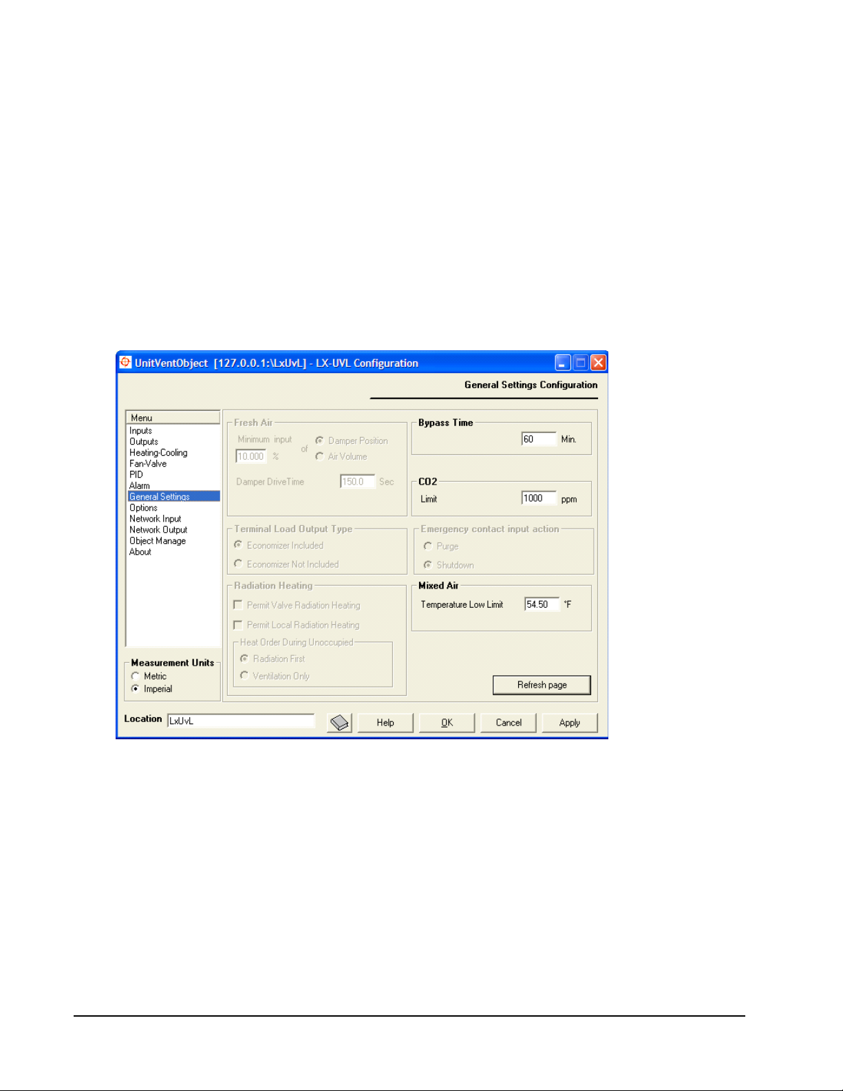
Control of the Fresh Air Intake
The fresh airflow is configured in the Unit Ventilator Controller configuration
wizard. You can control fresh airflow by one of the following options:
• Entering a minimum damper position on the general settings screen of the
UVC configuration wizard.
• Comparing mixed air temperature with return and outdoor air temperature.
Using this method, the amount of fresh air entering the system can be
calculated as a percentage of total air volume. This percentage is compared to
the minimum intake specified in the wizard. The result of this comparison is
used to move the damper.
Sensing the CO2 concentration within the space and using the output of the CO2
PID Loop to drive the damper (Figure 16).
Figure 16: Damper Control Settings on General Settings Screen
Outputs That Control the Fresh Air Damper
The fresh air damper is controlled by outputs Min_Fresh_Air_Enable, a digital
output, or Fresh_Air_Damper_Mod, a modulated output.
Min_Fresh_Air_Enable
This digital output is not for direct use with modulating dampers. It is intended for
use with an ON/OFF fresh air damper or automatic economizer control.
LX Series Unit Ventilator Controller User's Guide40
Page 41

Fresh_Air_Damper_Mod
If the damper is controlled with the Fresh_Air_Damper_Mod output, then the
damper is controlled in one of three ways:
• Demand Control Ventilation (DCV): If DCV is used, the damper is closed
when the CO2 level is lower than the CO2 concentration level set on the
General Settings menu of the UVC configuration wizard. As the CO
rises above this point, the damper modulates to reduce the CO
level while
2
level
2
maintaining the mixed air temperature or supply air temperature above the low
limits setpoint. The controller uses DCV whenever an input is configured as a
CO2 sensor.
• Return, Outdoor, and Mixed Air Temperatures: If the damper is controlled
by comparing return, outdoor, and mixed air temperatures, the fresh air damper
is set so that the amount of fresh air is slightly greater than or equal to the
minimum amount of fresh air expressed as a percentage of the total air volume.
To use return and mixed air temperatures, select Air Volume in the Fresh Air
Minimum input.
• Minimum Fresh Air Position: If there is no CO2 sensor and damper position
chosen on the General Settings menu, then the Fresh_Air_Damper_Mod
output uses the minimum fresh air position set on the General settings tab of
the Unit Ventilation Controller configuration wizard. If the discharge and
mixed air temperatures are not available, the damper is always fully closed or
in the minimum position set by Fresh Air Minimum Input.
Humidity Control
The UVC maintains the humidity level at the humidity setpoint that you enter on
the General Settings menu. The humidity setpoint is stored in
UCPThumidityLevelSetpoint. The fan speeds one, two, or three must be ON for
humidity control to function.
Humidification and dehumidification outputs have a minimum ON/OFF time. This
value is also entered on the General Settings menu.
You can perform humidity control using a PID loop. Enter the PID loop parameters
on the PID screen of the Rooftop Unit Controller configuration wizard. For a
description of PID loop control, see The PID Loop section.
The UV Controller maintains the humidity level at the humidity setpoint by the
following methods:
• switching ON or OFF the HUMIDIFIER_ON_OFF or
DEHUMIDIFIER_ON_OFF
• modulating the HUMIDIFER_MOD or DEHUMIDIFIER_MOD outputs
When you select any cooling output, it unlocks the Dehumidifying Settings. To
dehumidify with a cooling coil, you must enter a minimum cooling override value
and the fan speed override value. Dehumidification is more efficien t if the air goes
through the cooling coil slowly.
LX Series Unit Ventilator Controller User's Guide 41
Page 42

When you switch between humidification and dehumidification, the Rooftop Unit
Controller delays for a fixed time period of 45 minutes.
Cooling State
The Unit Ventilator Controller can control the following cooling types:
• free cooling
• digital cooling
• staged digital cooling
• cooling using heat pump
• floating valve cooling
• modulated valve cooling
The UVC uses free cooling or mechanical cooling. Free cooling uses the cooler
outside air to remove heat from the building. Mechanical cooling uses chiller units
and cooling coils to remove heat and humidity from the building.
Free Cooling
You can implement several strategies when using free cooling. The strategies can
be described by their following input requirements:
• economizer enable input
• outdoor enthalpy
• indoor and outdoor enthalpies
• outdoor air temperature
Economizer Enable Input: The economizer enable output follows the
economizer enable input if the input is available by network or by the hardware
input. If the economizer enable output is ON, then the fresh air damper can be used
for cooling when the mixed air temperature or the discharge air temperature is
known.
Outdoor Enthalpy: When outdoor enthalpy is available but not indoor enthalpy,
free cooling occurs if the outdoor enthalpy is below the maximum outdoor
enthalpy. A deadband of 0.43 Btu (1 kj/kg) is used in this process.
Maximum outdoor enthalpy is set on the Heating-Cooling configuration screen of
the Unit Ventilator Controller configuration wizard or by modifying
SCPToutdoorAirEnthalpySetpoint.
Outdoor and Space Enthalpies: If the outdoor and space enthalpies are available,
free cooling occurs if the outdoor enthalpy is 0.43 Btu (1 kj/kg) below the space
enthalpy. Free cooling is not available if the outdoor enthalpy exceeds the space
enthalpy.
Outdoor and space enthalpies are made available by the following methods:
• using a network input
LX Series Unit Ventilator Controller User's Guide42
Page 43

• using data from an enthalpy-calculating sensor
• using humidity and temperature from sensor or network inputs to calculate
enthalpies
Outdoor Temperature: If outdoor temperature is available, but not the enthalpy
and the economizer enable input, then free cooling occurs if the outdoor
temperature is below the maximum outdoor temperature. A deadband of 1.8 Fº
(1C°) space is used in this process.
Maximum outdoor temperature is set on the Heating-Cooling Configuration screen
or by modifying UCPTfreeCoolSetpoint.
Note: If discharge air temperature or mixed air temperature is not available, the
Fresh_Air_Damper_Mod output commands the fresh air damper closed or
to the fixed minimum position, depending on the fan state input value and
occupancy mode. The damper opens fully only during an emergency purge.
When Free Cooling is Used
The Rooftop Unit Controller uses free cooling when the following conditions
occur:
• The fan speeds 1, 2, or 3 are ON, or fan speed modulation is at the minimum
speed.
• All heating outputs have been OFF for the minimum amount of time defined
by the Change Over Delay option on the Heating-Cooling Configuration
screen UCPTchngeOverDelay.
• nviApplicMode must be set to HVAC_AUTO or HVAC_COOL.
• The space temperature input data must be valid, or the UVC must be slaved to
another unit.
• There must be a cooling demand. A cooling demand results from a comparison
between the space temperature and the active cooling setpoint.
Mechanical Cooling
The UVC turns the mechanical cooling outputs ON when all of the following
conditions occur:
• The fan speeds 1, 2, or 3 are ON, or fan speed modulation is at the minimum
speed.
• All heating outputs have been OFF for the minimum amount of time defined
by the Change Over Delay option on the Heating-Cooling Configuration
screen UCPTchngeOverDelay.
• nviApplicMode must be set to HVAC_AUTO or HVAC_COOL.
• The space temperature input data must be valid, or the Unit Ventilator
Controller must be slaved to another unit.
• The outdoor temperature must be greater than the Minimum Outdoor
Temperature entered on the Heating-Cooling Configuration screen.
LX Series Unit Ventilator Controller User's Guide 43
Page 44

• There must be a cooling demand. A cooling demand results from a comparison
between the space temperature and the active cooling setpoint.
• The fresh air damper, or economizer, must be at the minimum position.
• If a floating cooling valve is used, then one output must be
COOL_VALVE_OPEN and another output must be COOL_VALVE_CLOSE.
The water used for cooling and heating operations must be cold for any outputs,
configured as such, to work:
• heat_cool_valve_on_off
• heat_cool_valve_close
• heat_cool_valve_open
• heat_cool_valve_mod
The water is considered cold when the water temperature is colder than the room
temperature, or the nviHotWater received value or state is zero.
Note: nviHotWater has priority over the water temperature read from either the
input sensor or nviWaterTemp.
Cooling Demand
Cooling demand results from any one of the following:
• the error between the active cooling setpoint and the space temperature
• nviSlave
Cooling Output Sequence
If the Economizer Enable or Fresh_Air_Damper_Mod outputs are connected, and
the outside air temperature or outside air enthalpy has reached minimum low, then
free cooling is used before mechanical cooling; however, if free cooling cannot
satisfy the cooling demand, then the outside air damper is moved to the closed or
minimum position and mechanical cooling turns on.
If a cooling valve output is configured, then cooling outputs 1–4 turn ON only
after valve outputs are 100% open. Cooling outputs 1–4 are staged outputs–see the
Staged Outputs
section.
A delay occurs between the end of free cooling and the beginning of mechanical
cooling. This delay is defined by UCPTfree2MecDelay. You can set the delay on
the Heating Cooling screen by typing a value into the Switch Over Delay field.
Ending the Cooling State
Cooling outputs shut off when the bias reaches a negligible amount. However, if
the PID loop control has accumulated bias during the cooling stage, cooling
outputs may not shut off when the space temperature reaches the setpoint.
LX Series Unit Ventilator Controller User's Guide44
Page 45

Heating States
The Unit Ventilator Controller controls the following heating types:
• digital heating
• staged digital heating
• heat pump heating
• floating valve heating
• modulated valve heating
The Unit Ventilator Controller turns the heating outputs ON when the following
conditions are present:
• Fan speeds 1, 2, or 3 are ON, or fan speed modulation is at the minimum speed.
• Permit valve radiation heating and/or Permit local radiation heating options
are selected.
• All cooling outputs must be OFF for the period of time defined as a Change
Over Delay on the Heating Cooling Configuration screen, unless another input
is configured as a reversing valve. If another input is configured as a reversing
valve, the first stage of cooling turns ON at the same time as the reversing
valve. See the Cooling Outputs Used to Heat section.
Note: You can also use cooling outputs to dehumidify. In this situation, you can
enable both cooling and heating outputs at the same time. The option to
disable dehumidification in heating mode was designed to avoid this
situation by keeping the cooling outputs OFF for dehumidifying in heating
mode.
• The network variable nviApplicMode must be set to HVAC_AUTO or
HVAC_HEAT.
• The UVC must receive the space temperature or it must be slaved to another
unit through nviSlave. Space temperature can be received through a hardware
input or through nviSpaceTemp.
• There must be heating demand. See the following Heating Demand
section.
• If a floating heating valve is used, one output must open the heating valve and
another output must close the valve.
The water source used for the heating coils must be hot for the following control
outputs to work:
• HEAT_COOL_VALVE_ON_OFF
• HEAT_COOL_VALVE_OPEN
• HEAT_COOL_VALVE_CLOSE
• HEAT_COOL_VALVE_MOD
The water is considered hot when the water temperature is warmer than the room
temperature, or when nviHotWater receives a value and states different from zero.
LX Series Unit Ventilator Controller User's Guide 45
Page 46

Note: The nviHotWater variable has priority for the water temperature either
from the input sensor or nviWaterTemp.
Heating Demand
Heating demand results from any one of the following:
• an error between the active heating setpoint and space temperature
• nviSlave
If heating demand is taken from nviSlave, then the Unit Ventilator Controller is
operating in slave mode and is receiving the heating demand from another unit.
Heating Output Sequence
Heating outputs 1–4 are staged outputs. Heating output 1 is the first heating stage
in the stage sequence. See the Staged Outputs section for more information.
Heating outputs 1–4 and Heating_Mod do not turn ON until all heating valve
outputs are at 100%.
Cooling Outputs Used to Heat
You can use cooling outputs 1–4 to heat if another output is configured as a
reversing valve. The reversing valve turns ON at the same moment as the first
stage of cooling.
If the cooling outputs are used to heat, then heating outputs 1–4 and Heating_Mod
do not turn on until the cooling outputs are at 100%.
Ending the Heating State
The heating state ends when there is no demand for heating, and the first heating
stage (if any) has operated for more than the minimum heating period.
If the PID loop control has accumulated bias during the heating stage, heating
outputs may not shut off when the space temperature reaches the setpoint. The
output shuts off when the bias reaches zero.
Night Purge
Night purge is used to freshen the building air before occupation or to cool down a
building before morning occupation. Night purge is a scheduled operation that
does not use any setpoints. During night purge, only free cooling is enabled. The
damper and fan respond to the cooling demand; heating and cooling outputs are
OFF.
The Unit Ventilator Controller enters night purge if nviApplicMode is set to
HVAC_NIGHT_PURGE. This can be the result of binding with a supervisory
Heating, Ventilating, and Air Conditioning (HVAC) device, an HMI, or a
scheduling system.
If frost protection is enabled, the heat turns ON if the temperature in the
conditioned space reaches 42.8°F (6°C) and turns OFF at 46.4°F (8°C).
LX Series Unit Ventilator Controller User's Guide46
Page 47

Morning Warm-up State
The Unit Ventilator Controller enters the morning warm-up state when
nviApplicMode has the value of HVAC_MRNG_WRMUP. This value of
HVAC_MRNG_WRMUP may be the result of binding nviApplicMode with a
network variable from a supervisory network system such as nvoTerminalLoad.
The morning warm up period uses occupied setpoints. The fresh air damper is
closed if there is no cooling demand. Morning warm up ends when
nviApplicMode commands another state.
Using Night Purge and Morning Warm-up with DCV
The UV provides DCV by using the CO2 sensor to measure air quality . While CO2
is a reliable gauge of the effect of human metabolism upon air quality, it does not
provide any measure of other effects upon air quality. For example, various glues
and plastics release gases for an extended period of time after installation in a new
building. These gases can produce unpleasant odors and cause eye, nasal, as well
as bronchial irritation. The accumulation of these gases does not affect the CO2
level. If CO2 alone is considered, the concentration of these gases may not be
sufficiently reduced during occupied periods to ensure the comfort and health of
the building occupants.
Similarly, an unoccupied building can accumulate gases and odors caused by
clothing left in lockers, damp drains, and photocopiers programmed to produce
manuals during the night. None of these detriments to air quality is detected by a
CO2 sensor.
Such problems can be solved by over-ventilating, which is expensive, or by
providing a minimum airflow during unoccupied periods. Another solution is to
use the night purge or morning warm-up to exhaust the accumulated gases before
the start of normal occupation.
While the building is unoccupied, CO2 levels do not increase. Yet the levels of
other contaminants increase. During occupied periods, these contaminants may not
be removed by a DCV system that responds only to CO
morning warm-up remove all contaminants by flushing the building with fresh air
before the occupied period.
levels. Night purge and
2
Fan Operation
Three fan speeds are available in the UVC. Fan speeds are started according to the
heating or cooling demand and according to the outputs configured in the Unit
Ventilator Controller configuration wizard. Normal operation sequence begins
with the UVC commanding the first fan speed to turn ON. After this, the UVC
starts or modulates all cooling and heating outputs to their maximum capacity
according to their respective demands. Finally, all other fan speeds are started
according to their respective demands.
LX Series Unit Ventilator Controller User's Guide 47
Page 48
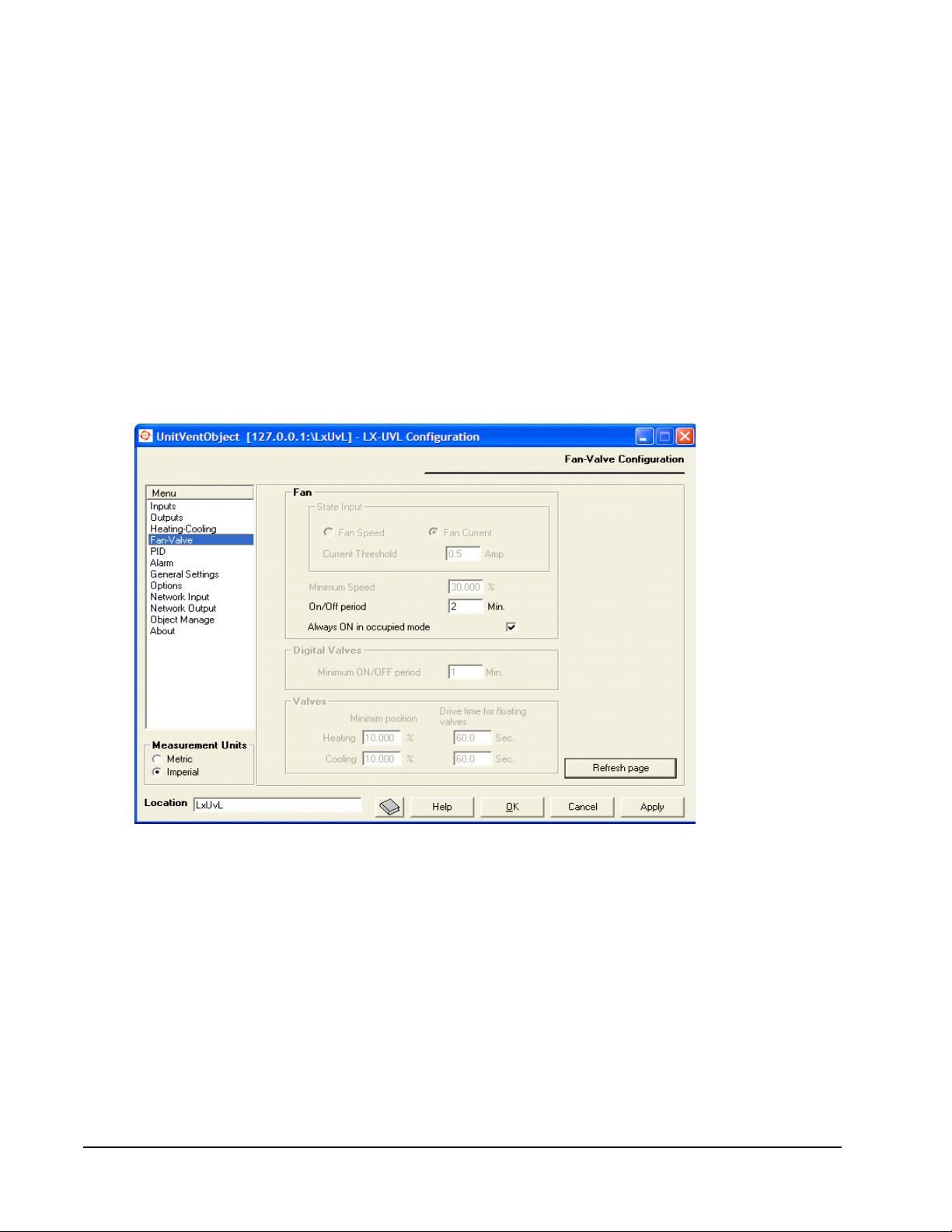
If the fan option Always On in occupied mode is selected and the occupancy status
is OC_OCCUPIED or OC_BYPASS, the first fan speed is ON. Otherwise, the first
fan speed starts according to a cooling or heating demand.
Fan speeds two and three are controlled by a cooling and heating demand.
However, heating outputs and cooling outputs must be configured so these fan
speeds can start.
Fan speeds two and three are used to increase cool or hot air volume in the room.
For example, during a heating demand, it would not be appropriate to increase the
air volume if the discharge air is not reheated. This situation creates discomfort for
room occupants as they receive colder air.
The minimum time that any fan speed must be ON before it turns OFF, and the
minimum time that any fan speed must be OFF before it turns ON, are both set in
the Fan-Valve screen of the UVC configuration wizard. Enter a value in the ON/
OFF period box on that screen. See Figure 17.
Figure 17: Fan-Valve Screen of the Unit Ventilator Controller
Configuration Wizard
Terminal Load
T erminal load describes the ener gy consumption of a Unit Ventilator Controller for
both heating and cooling operations. The effect of the economizer damper may be
included or excluded from the terminal load on the General Settings screen. The
network variable nvoTerminalLoad transmits the terminal load of the controller
over the network.
LX Series Unit Ventilator Controller User's Guide48
Page 49

Heating Terminal Load
Negative terminal load numbers represent the heating terminal load. Heating effort
increases as the terminal load decreases. At 100% heating effort, the terminal load
is -100% (Figure 18).
Heating Terminal Load
Terminal Load
0%-50%-100%
Time
0%
50%
100%
Heating
Effort
Figure 18: Heating Terminal Load
LX Series Unit Ventilator Controller User's Guide 49
Page 50
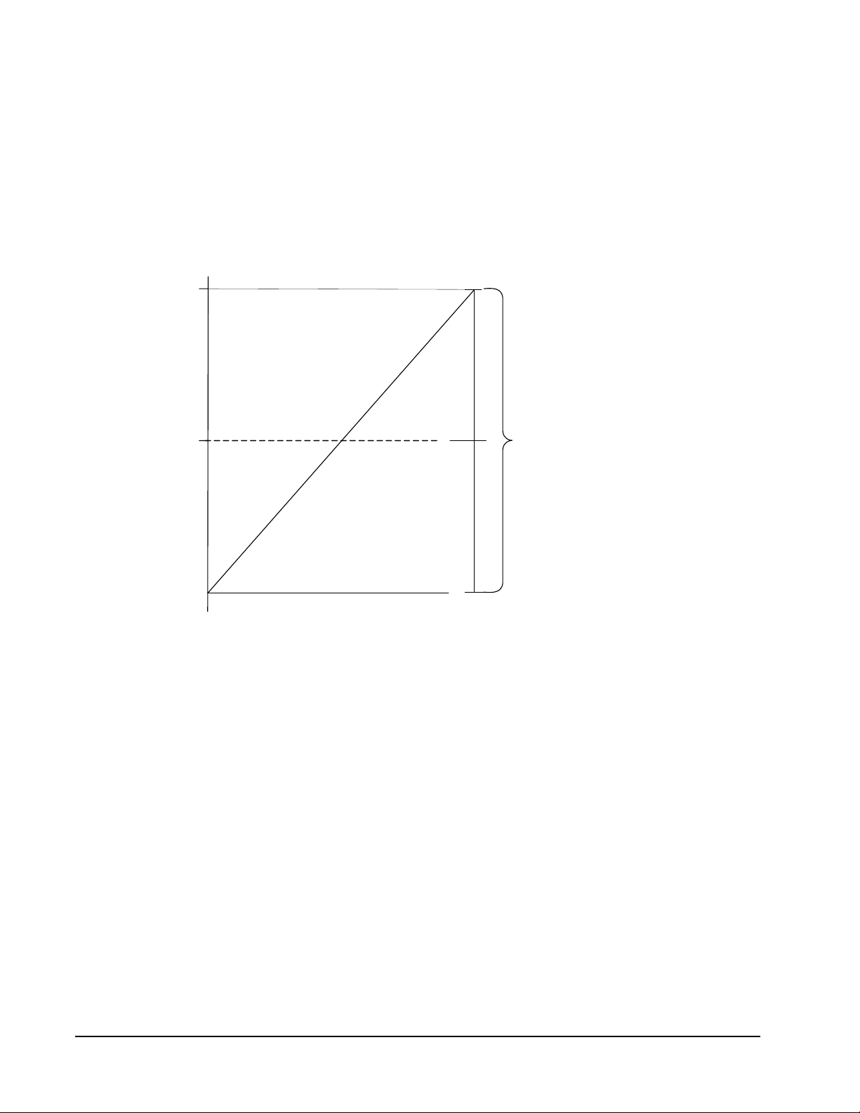
Cooling Terminal Load
Positive numbers represent the cooling part of terminal load. The terminal load
increases as cooling effort increases. At 100% cooling effort, the terminal load is
100% (Figure 19).
Cooling efforts often have two components: a fresh air damper that can be used to
cool the building if outside air is cool enough, and a mechanical cooling system
composed of cooling coils that carry heat away from the circulating air.
Cooling Terminal Load
Terminal Load
100%
50%0%
100%
50%
Time
0%
Figure 19: Cooling Terminal Load
Cooling
Effort
LX Series Unit Ventilator Controller User's Guide50
Page 51

Networking Operations
This section describes the operations that occur only as a result of network
connections, and provides a description of network variable properties.
Slave Operation
The UVC follows the demands of another unit ventilation controller if nviSlave is
bound to the nvoUnitStatus of another unit ventilation controller. The network
variable nviSlave is type SNVT_hvac_status.
Load Shedding
If the Unit Ventilator Controller receives an input on nviShedding, it reduces its
output. As the value of nviShedding increases, the UVC further reduces its output.
For example, if nviShedding is at 25%, heating and cooling outputs do not exceed
75%.
Shedding is stopped if frost protection is enabled, and space temperature falls
under 46°F (8°C). The network variable nviShedding is type SNVT_switch.
Setting up Network Connections
The Unit Ventilator Controller interfaces through the Local Operating Network
(LON) to other unit ventilators, HMI, and other LONWORKS Network Services
(LNS®) based software using the LonTalk® protocol and LNS services.
Whereas the UVC can function without a network connection, the network
variables sent and received over the LON by the controller can affect all of its
operations.
LX Series Unit Ventilator Controller User's Guide 51
Page 52
Network Outputs
The network variables have several important attributes in common. These
attributes include Heartbeat, Send on Delta, and Throttle.
Table 7 defines the network variable attributes. Table 8 describes the network
inputs.
Table 7: Network Outputs
Attribute Description
Heartbeat Heartbeat is the maximum amount of time that must pass before the network
variable automatically transmits. The presence of the heartbeat attribute
indicates that functions are proceeding normally. Failure to receive a signal at
the other node within a heartbeat interval causes an alarm message to be
sent over the network.
Heartbeat is like a countdown timer. Only when the heartbeat timer reaches
zero is the heartbeat message sent. Every time that a message is sent, the
Heartbeat timer resets to the full heartbeat value.
Heartbeat signals are not always sent. If the monitored data changes more
than is required by the Send on Delta setting within a shorter period of time
than the heartbeat, the data is sent on the network and the heartbeat
message is not sent. Instead, the heartbeat timer is reset and begins to count
down again.
Heartbeat provides a method of ensuring that points have not lost connection
and that the network is functioning. Whereas throttle restricts how often
messages are sent, heartbeat ensures that messages are sent regularly.
Heartbeat is disabled by settin g it to zero .
Send on Delta Send on Delta causes a message to be sent when the monitored data
Throttle Throttle sets the minimum update period. Throttle acts as a limit on excessive
changes by a previously set proportion. Send on Delta restricts extraneous
network noise by allowing only signals that indicate a meaningful amount of
change.
If the monitored data does not change for a period of time equal to the
heartbeat interval, the data is sent as a heartbeat signal.
network traffic. If the value of a point on the network is constantly fluctuating
at a rapid rate and is set to Send on Delta, the network can be flooded by data
from that point. Throttle prevents the variable from transmitting more than
once every minimum update period regardless of how many fluctuations have
occurred during that period. For example, rapid motion of the damper could
drastically increase network traffic. Damper oscillations could also cause
network traffic problems if data were sent on every cycle of oscillation.
Throttle can prevent network congestion in either of these cases by limiting
the number of sends per time interval to a meaningful number.
Throttle units are in seconds. The larger the throttle number, the less
frequently the network variable is transmitted.
You can disable throttle by setting it to zero.
Table 8: Network Inputs
Attribute Description
Heartbeat The Heartbeat effect on a network input is set to the maximum time period
that the network variable waits for a message before entering the heartbeat
failure state. When a heartbeat failure state is entered, the value becomes
invalid and an alarm is sent.
Persistent When the network variable is marked as persistent, the value is written to
EEPROM. Once written to EEPROM, the network variable value is preserved
through power outs and resets. Every time a new network variable value is
received, the new value is written into EEPROM.
Because EEPROM can only accept a limited number of data writes, be
careful how you use the persistent attribute. See the Persistent Network
Variables section for more information.
LX Series Unit Ventilator Controller User's Guide52
Page 53

Optimum Start
Optimum Start prepares the space for occupancy in advance of the occupied
period. If you start heating or cooling at the optimum time before the occupied
period begins, the UVC provides a comfortable space that is ready for occupancy
without wasting energy. Enable Optimum Start on the Options screen of the Unit
Ventilator Controller configuration wizard. Select the boxes labeled Enable
Optimum Start for heating and Enable Optimum Start for cooling.
The UVC maintains statistics that compare the outside temperature to the time
required for the space to reach the occupied setpoints. The UVC uses the statistics
to calculate the length of time required for Optimum Start.
Because the Optimum Start time is calculated every day for the current outside air
temperature, it is much more energy efficient than simply starting the occupancy
period before the actual arrival of occupants.
Enter a value in the Maximum start time box to limit the Optimum Start time
period. Optimum Start begins no sooner than the Maximum start time before the
occupancy change. For example, if the space enters the occupied mode at 8:00
A.M. and the Maximum start time is 30 minutes, then Optimum Start does not
begin until 7:30 A.M. at the earliest. Of course, Optimum Start can still begin at
any time that is less than 30 minutes before 8:00 A.M.; for example, 7:41 A.M.
When statistics are not available, you can choose from two options. The first
option starts heating or cooling when the space occupancy changes. The second
option allows Optimum Start to use the Maximum start time. To enable this
feature, select the box labeled Use maximum time if no statistics on the Options
configuration screen or set bit #58 of the network variable to UCPTobjectoptions.
Regardless of which setting you choose, the first samples are saved when the UVC
does not have any statistics; these samples include the outside air temperature and
the time required to reach the setpoint. Each day, Optimum Start uses the time
recorded from the previous day’s sample. For example, if the Unit Ventilator
Controller recorded that the space reached occupied setpoint in 25 minutes the first
day, then on the second day the UVC would begin Optimum Start 25 minutes
before occupancy. If a maximum start time has been entered, the UVC may use a
value derived from the samples that is less than the maximum start time. However,
the controller does not use a start time that is greater than the maximum start time
value.
On the third day, the UVC has two samples stored and uses the two samples to
calculate the Optimum Start time given the current outdoor temperature. From this
point on, all Optimum Starts are statistically calculated by the UVC using its saved
samples.
Requirements for Optimum Start
The next state and time to the mode must be defined in advance. There must be a
scheduler and the schedule must be properly bound to the Unit Ventilator
Controller using nviOccCmd.
LX Series Unit Ventilator Controller User's Guide 53
Page 54

The network variable nviOccCmd must be set to SNVT type SNVT_tod_event.
You can do this using the Changeable Nv Manager view of the device.
Because the Optimum Start is based on statistics calculated from the room
temperature and the outside air temperature, the outdoor temperature must be
configured as an input or be received from the network through nviOutdoorTemp.
Emergency Operation
Emergency modes are primarily for situations where the ventilation system may
affect the spread of smoke or other contaminants. There are two possible
situations:
• You want to keep fresh air from entering the building, such as to slow the
spread of a fire.
• You want to allow fresh air into the building.
As a result, the unit ventilator has two emergency modes:
• Emergency Purge: An emergency purge stops the fan, stops any heating or
cooling, and fully opens the fresh air damper.
• Emergency Shutdown: An emergency shutdown stops the fan, stops any
heating or cooling action, and closes the fresh air damper.
LX Series Unit Ventilator Controller User's Guide54
Page 55
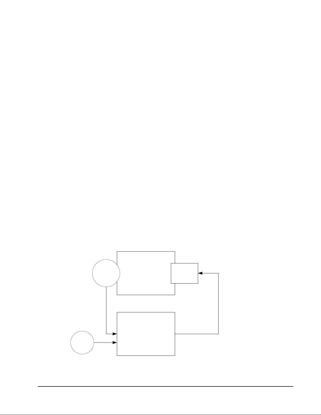
Emergency Initiation
Emergency modes are initiated by:
• Setting nviEmergCmd to EMERGE_PURGE or EMERG_SHUTDOWN.
• Closing the emergency contact wired to the emergency input.
The network variable nviEmergCmd has priority over the emergency contact. The
network variable nviEmergCmd is a SNVT_hvac_emerg (103) type. Invalid value
is EMERG_NUL.
The emergency contact input can be configured as emergency pur ge or emer gency
shutdown on the General Settings screen of the UV configuration wizard.
Otherwise, you can modify UCPTobjectOptions:
• Setting bit 54 to 0 selects emergency purge.
• Setting bit 54 to 1 selects emergency shutdown.
Normal Operation
When there is no emergency and operations are normal, nviEmergCmd is set to
EMERG_NORMAL.
The PID Loop
Proportional plus Integral plus Differential (PID) loops provide precise control
over space temperature and ventilation.
The control loop modulates its output to drive its input to a setpoint. The control
loop inputs are the sensor readings of the temperature. For example, the outputs
can be the fan speeds and the heating or cooling outputs.
The difference between the input and the setpoint is called the error . The controller
output is a function of the error.
SpaceSensor Output
Input
Controller
Setpoint
Output
Figure 20: PID Controller with Input, Setpoint, and Output
LX Series Unit Ventilator Controller User's Guide 55
Page 56

The Unit Ventilator Controller provides PID control settings through its
configuration wizard. Figure 21 shows the PID screen.
Figure 21: PID Screen of the Unit Ventilation
Controller Configuration Wizard
For space temperature, discharge temperature, CO2, and humidity levels, there are
settings for proportional, integral, and derivative gains. Each of these gains
contributes to the final output as shown in Figure 22. They are discussed separately
in the following sections.
Proportional
Figure 22: Total Output Composed of P, I, and D Components
++ =
Integral
Derivative
Tota l O u tp ut
Proportional
Proportional control provides an output that is proportional to the error. The error
is multiplied by a number called the gain. The result is used to produce the output.
For example, if the room temperature is 69°F and the setpoint is 72°F, then the
error is 3F°. If the gain is equal to 10% per °F, then the output is 30% of the
maximum output value.
Integral
The integral component has a gain and time setting. These work together to
remove errors that accumulate over time.
LX Series Unit Ventilator Controller User's Guide56
Page 57

Gain
Gain is a multiplication factor that adds weight to the integral part of the PID loop.
The integral gain is similar to the proportional gain. The error is multiplied by the
value you entered as integral gain. If the gain is equal to 5% per °F and the error is
2F°, the integral output is 10% of the maximum possible output signal.
The integral gain differs from the proportional gain in that the output is increased
the longer that the error persists. This situation occurs because the product of the
error multiplied by the integral gain is periodically added to the output. When you
enter the time, you are entering the length of the time period over which the error is
added.
Time
Time is the cycle period for the integral part of the PID loop. The cycle period is
the time necessary for the integral error to attain the same value as the proportional
error.
How It Is Used
Imagine a building in a cold climate where the temperature of a certain space is
never quite warm enough. A log of the temperature of this space would produce a
graph such as Figure 23.
Heat is OFF.
Setpoint
Heat is ON
Temperature
8:00 8:30 9:0010:00
Time
Figure 23: Never Quite Warm Enough:
Using Only a P Controller
Space Temperature
In Figure 23, the temperature never quite falls low enough to turn on the
proportional heat.
LX Series Unit Ventilator Controller User's Guide 57
Page 58

However, with a proportional integral controller, the error would accumulate over
time. Periodically, a portion of the error would be added back into the error. Error
would accumulate and would finally be large enough to turn on the heat. See
Figure 24.
Space
Heat is OFF.
Setpoint
Temperature
Heat is ON
Temperature
8:00 8:30 9:0010:00
Time
Figure 24: Heating Using a PI Controller
Heat is ON.
Error accumulates.
Derivative
Derivative control opposes sudden changes in the input value. Whereas integral
control is able to correct errors that persist over time, derivative control can
respond to sudden changes quickly.
Consider a graph of temperature over time. Because the derivative of a function is
the rate of change of the function, the derivative of temperature over time is the
rate of change of the temperature per unit time. For example, rate of change could
be degrees per minute.
Derivative control opposes the rate of change. For example, consider a hospital
lobby in the arctic. Because the lobby changes temperature often, it has its own
local heaters that are controlled by a PID loop. Every time the hospital doors open,
the temperature in the lobby quickly decreases. This sudden drop in temperature is
a considerable rate of change. This considerable rate of change is opposed by the
derivative control. The derivative control increases the output of the PID loop that
increases the output of the heaters. As the lobby temperature becomes closer to the
setpoint, the derivative control output decreases to zero as the lobby temperature
reaches its setpoint.
Gain
The derivative gain is the amplification of the derivative output. The gain is
measured as a percentage per unit of change where a unit is a Centigrade or
Fahrenheit degree. If 50 is entered into the Gain box, then each unit of error causes
a 50% increase in derivative control output.
LX Series Unit Ventilator Controller User's Guide58
Page 59

Time
Derivative control normally responds to measured values rather than the actual
direct input. By doing so, the derivative control is prevented from creating large,
short spikes in the controller output. The spikes are the derivative control response
to sudden increase or decrease in error due to setpoint changes.
Time refers to the period between measurements of the input. If the time is set to
3 seconds, and the gain is 25%/F°, then the derivative output is 25% of the error
for each degree of error and recalculates every 3 seconds.
Deadband
The deadband is a range of input values. The center of the range is the setpoint.
While the input lies within the deadband, deviations from the setpoint are not
calculated as errors. The deadband is the range of values that are close enough to
the setpoint that their effect is unnoticeable.
If the deadband is equal to 1/2 x to the setpoint + 1/2 x, then the deadband extends
from the setpoint - 1/2 x to the setpoint + 1/2 x. The maximum amount of deviation
allowed is ± 1/2 x. See Figure 25.
Deadband with Value of x
As long as input stays within the deadband, the error
will be zero. As long as the error is zero, the PID loop
Deadband Limits
e
d
u
t
i
n
g
a
M
Deadband Limits
0.5x
x
0.5x
Setpoint
will not change its output signal.
As soon as the input exceeds the
deadband, the PID loop will sense
an error at its input. Whatever the
PID outputs will do next, depends
Time
on the PID loop settings.
Input
Figure 25: Effect of Deadband upon PID Loop Error
When you use deadbands, it reduces mechanical wear and tear on moving parts
because the mechanical parts no longer oscillate to accommodate trivial errors.
LX Series Unit Ventilator Controller User's Guide 59
Page 60

Alarm Operation
Shown in Figure 26, the Alarm Configuration screen of the Unit Ventilator
Controller configuration wizard provides user-set alarms. You can configure and
enable these alarms to match the requirements of your current site. User-set alarms
are available for the following control points:
• space air temperature
• discharge air temperature
• return air temperature
• mixed air temperature
• space humidity
• auxiliary alarm
• fan alarm
• pump alarm
In addition to the preceding user-set alarms, other alarms are provided. These
include:
• heartbeat alarms for network inputs
• disconnect alarms for sensor points
• emergency mode alarm
Figure 26: Alarm Configuration Screen
LX Series Unit Ventilator Controller User's Guide60
Page 61

Alarm Features
UVC alarms have a number of features that enable you to automatically and
carefully monitor critical system information. Many of these features are visible in
Figure 27. Table 9 describes alarm features.
Features of a Deviation Alarm
Space Temp C°
Offset = 2C°
Alarm Delay = 10 minutes
10.0 min
Monitored
Variable
25
Setpoint
22
20
15
Time
Monitored variable exceeds value of offset + setpoint
at this time.
An alarm message is not sent as the monitored
variable is in the alarm state for less time than the
value of the alarm delay.
2.0 C°
2.0 C°
10.0 min
Monitored variable
enters alarm state
at this time.
Alarm message is
sent here after the
expiration of the
alarm delay.
Upper
limit of
Offset
Lower
limit of
Offset
Figure 27: Space Temperature Alarm
Table 9: Alarm Features (Part 1 of 2)
Feature Description
Monitored Variable Displays the network variable or control point that is monitored by the
Alarm State Enables when a monitored variable has a value that causes an alarm.
Alarm Offset Displays the amount that the monitored variable can deviate from the
Alarm Delay Displays the period of time that the monitored variable must be in the
alarm. For example, if you have an alarm that sends a message
whenever a space temperature deviates too far from the setpoint, then
the monitored variable is the space temperature.
setpoint before entering the alarm state. See Figure 27. An offset
causes the alarm to become active when the value of the monitored
variable is greater than or less than the range of values equal to the
setpoint plus or minus the offset. Alarms that use an alarm offset are
often called deviation alarms.
alarm state before an alarm message is generated. See Figure 27 and
Figure 28.
LX Series Unit Ventilator Controller User's Guide 61
Page 62

Table 9: Alarm Features (Part 2 of 2)
Feature Description
Alarm Low Limit Displays a value that is less than the setpoint. When the monitored
Alarm High Limit Displays a value that is greater than the setpoint. When the monitored
variable becomes equal to or less than the alarm low limit, an alarm
message is transmitted over the network. Alar ms tha t use a low limit
are often called low limit alarms. See Figure 28.
variable becomes equal to or more than the alarm high limit, an alarm
message is transmitted over the network. Alarms using high limits are
often called high limit alarms. See Figure 28.
Alarms are transmitted using the network variables nvoUValarm and
nvoUnitStatus.
A number of alarms respond to the timing of network variables. Some of these are
called heartbeat alarms because they respond to the heartbeat value. The heartbeat
is the maximum length of time that can occur between transmissions of a variable
on the network. If this time is exceeded, an alarm sounds.
Alarm Types
The UVC uses four types of alarms. Table 10 describes these alarm types.
Table 10: Alarm Types
Alarm Type Description
Digital Alarms Monitors the state of digital network variables or hardware inputs. Digital
High Limit Alarms Reports when an analog network variable or hardware input is greater
Low Limit Alarms Reports when an analog netw ork variable or hardware input is less than
Deviation Alarms Reports when a monitored analog value deviates from its setpoint by
alarms can also indicate when digital network variables differ in state.
For example, the fan output and the fan state should always be the
same. If they differ, a digital alarm transmits a message on the network.
than a user-set value called a high limit.
a user-set value called a low limit.
more than a user-set value known as an alarm offset.
Alarm Procedure
When an alarm condition occurs, the following changes take place:
• The appropriate bits of nvoStatus and nvoUValarm are set.
• The in_alarm field of nvoUnitStatus is set to 1.
• The network variable nvoUnitStatus transmits information about the unit
ventilator object.
The following text sorts the alarms by type, describes the conditions that generate
an alarm, and organizes the associated bits of the nvoStatus and nvoUValarm into a
table.
LX Series Unit Ventilator Controller User's Guide62
Page 63

The alarm types are:
• heartbeat alarms
• disconnect alarms
• status alarms
• user-set alarms
Features of an Alarm Using High and Low Limits
Lower Alarm Limit = 18°C
Supply Temp C°
Upper Alarm Limit = 24°C
Alarm Delay = 10 minutes
10.0 min
25
22
Setpoint
20
18
15
Time
Monitored variable falls below lower limit.
An alarm message is not sent as the monitored
variable is in the alarm state for less time than the
value of the alarm delay.
Heartbeat Alarms
Monitored
Variable
10.0 min
Monitored variable
enters alarm state
at this time.
Alarm message is sent at
this time after the expiration
of the alarm delay.
Figure 28: Discharge Temperature Alarm
Upper
Alarm
Limit
Lower
Alarm
Limit
Heartbeat time values are set on the Network Input screens of the Unit Ventilator
Controller configuration wizard or by modifying SCPTmaxRcvTime.
The column heading Bit # refers to the Bit Number of nvoUValarm. The column
programmatic name refers to the programmatic name of nvoUValarm with the
format type UNVT_uv_alarms that relays the status of the object. If a heartbeat
alarm comes ON, a communication failure alarm sounds. The Bit #13 of
nvoStatus, programmatic name comm_failure, turns ON. Table 11 describes
Heartbeat Alarms.
LX Series Unit Ventilator Controller User's Guide 63
Page 64
Table 11: Heartbeat Alarms
Monitored
Point
Application Mode
CO2
Concentration
Discharge
Temperature
Economizer
Enable
Fan Speed
Command
Fan State
Hardware Output
Value
Mixed Air
Temperature
Occupancy
Command
Outdoor Enthalpy
Outdoor Humidity
Outdoor
Temperature
Return
Temperature
Setpoint Offset
Shedding
Command
Slave Input
Space Enthalpy
Space Humidity
Space
Temperature
Water
Temperature
Water
Temperature St ate
(Hot/Cold)
Monitored
Variable
nviApplicMode SCPTmaxRcvTime 1 nviApplicModeHeartBeat
nviCO2 SCPTmaxRcvTime 14 nviCO2HeartBeat
nviDischargeTemp SCPTmaxRcvTime 6 nviSupplyTempHeartBeat
nviEconEnable SCPTmaxRcvTime 8 nviEconoHeartBeat
nviFanSpeedCmd SCPTmaxRcvTime 19 nviFanSpeedCmdHeartBeat
nviFanState SCPTmaxRcvTime 7 nviFanStateHeartBeat
nviExtCmdOutput(x)SCPTmaxRcvTime 20
nviMixAirTemp SCPTmaxRcvTime 16 nviMixedAirTempHeartBeat
nviOccCmd SCPTmaxRcvTime 3 nviOccCmdHeartBeat
nviOutdoorEnth SCPTmaxRcvTime 18 nviOutdoorEnthHeartBeat
nviOutdoorRh SCPTmaxRcvTime 13 nviOutddoorRhHeartBeat
nviOutdoorT emp SCPTmaxRcvTime 11 nviOutdoorTempHeartBeat
nviReturnTemp SCPTmaxRcvTime 15 nviReturnTempHeartBeat
nviSetptOffset SCPTmaxRcvTime 2 nviSetPtOffsetHeartBeat
nviShedding SCPTmaxRcvTime 9 nviSheddingHeartBeat
nviSlave SCPTmaxRcvTime 10 nviSlaveHeartBeat
nviSpaceEnth SCPTmaxRcvTime 17 nviSpaceEnthHeartBeat
nviSpaceRH SCPTmaxRcvTime 12 nviSpaceRHHeartBeat
nviSpaceTemp SCPTmaxRcvTime 0 nviSpaceTempHeartBeat
nviWaterTemp SCPTmaxRcvTime 4 nviWaterTempHeartBeat
nviHotWater SCPTmaxRcvTime 5 nviHotWaterHeartBeat
Delay Time Bit#Programmatic Name
nviExtCmdOutputxHeartBeat
26
LX Series Unit Ventilator Controller User's Guide64
Page 65

Disconnect Alarms
The column heading Bit # refers to the Bit Number of nvoUValarm. The column
programmatic name refers to the programmatic name of nvoUValarm with the
format type UNVT_uv_alarm that relays the status of the object. If a heartbeat
alarm comes ON, an electrical fault alarm sounds. The Bit #11 of nvoStatus,
programmatic name electrical_fault, turns ON. Table 12 describes disconnect
alarms.
Table 12: Disconnect Alarms
Sensor Time
Disconnected
Space Temperature
Sensor
Discharge Air Temperature
Sensor
Return Air Temperature
Sensor
Mixed Air Temperature
Sensor
Outdoor Air T emperature
Sensor
Water Temperature Sensor 30 seconds 37 WaterTempSensorFault
Setpoint Offset 30 seconds 38 SetpointOffs et El ecF a ul t
30 seconds 32 SpaceTempSensorFault
30 seconds 33 DischargeTempSensorFault
30 seconds 34 ReturnTempSensorFault
30 seconds 35 MixedAirTempSensor
30 seconds 36 Out doorTempSensor
Bit # Programmatic Name
Emergency Mode Alarms
Emergency mode is described in the Emergency Operation section. Emergency
mode alarm begins when the emergency mode begins. In Table 13, the column
programmatic name refers to the programmatic name of nvoUValarm with the
format type UNVT_uv_alarm, which relays the status of the object.
Table 13: Emergency Mode Alarm
Monitored State Bit # Programmatic Name
Emergency Mode 48 Emergency
User-Set Alarms
The column heading Bit # refers to the Bit Number of nvoUValarm. The column
programmatic name refers to the programmatic name of nvoUValarm with the
format type UNVT_rt_alarm that relays the status of the object. If a user-set alarm
comes ON, an out of limits alarm sounds. The Bit #4 of nvoStatus, programmatic
name out_of_limits, turns ON.
LX Series Unit Ventilator Controller User's Guide 65
Page 66
These settings can be entered on the Alarm screen of the Unit Ventilator Controller
configuration wizard (Figure 26). Table 14 describes the configuration variables
for user-set alarms.
Table 14: Configuration Variables for User-Set Alarms
Monitored
Point
Space
Temperature
Discharge Air
Temperature
Return Air
Temperature
Mixed Air
Temperature
Space
Humidity
CO2
Concentration
Fan State
Auxiliary
Alarm Input
Alarm
Type
Deviation Active heating
Low Low limit setpoint 41 LowDischargeTemp UCPTsupplyTempA
High High Limit
Deviation active heating
Low low limit setpoint 45 LowMixedAirTemp UCPTmixAirTemp
Deviation setpoint - offset 46 LowSpaceRH UCPThumidity
High CO2 Limit +
Digital Fan input differs
Low lower than low
High higher than high
Setpoints Bit#Programmatic
Name
setpoint-offset
Active cooling
setpoint+offset
setpoint
setpoint-offset
active cooling
setpoint+offset
setpoint + offset 47 HighSpaceRH
offset
from state of fan
output
limit setpoint
limit setpoint
39 LowSpaceTemp UCPTspaceTemp
40 HighSpaceTemp
42 HighDischargeTemp UCPTsupplyT empA
43 LowReturnT emp UCPTreturnTemp
44 HighReturnT emp
48 HighCO2Level UCPTCO2Alarm
49 FanStateMismatch UCPTFanCurrent
50 AuxiliaryLowAlarm UCPTauxiliary
51 AuxiliaryHighAlarm UCPTauxiliary
Setpoints/Delta
Location
AlarmDelta Field
larmLoLimit Field
larmHiLimit Field
AlarmDelta Field
Alarm LoLimit Field
AlarmDelta Field
Delta Field
Threshold
AlarmLoLimit field
AlarmHiLimit field
Time Delay
Location
UCPTspaceTemp
AlarmTime Field
UCPTsupplyTemp
AlarmTime Field
UCPTreturnTemp
AlarmTime Field
UCPTmixAirTemp
AlarmTime Field
UCPThumidity
AlarmTime Field
UCPThumidity
AlarmTime Field
UCPTfanAlarm
Time
UCPTauxiliary
Alarmtime field
Setting up the Unit Ventilator Controller
This section provides you with step-by-step instructions for setting up the Unit
Ventilator Controller using the configuration wizard. The definition of the terms
used in the configuration wizard and a short explanation of how to use each section
of the configuration wizard are provided.
Each screen of the configuration wizard is discussed under its own heading (for
example, Heating-Cooling Configuration) and introduced by a large graphic of
that screen.
The following information is in the same order as it appears in the Unit Ventilator
Controller configuration wizard.
Persistent Network Variables
Note: Read this section about how to make network variables persistent. This
information could save you a great deal of time.
LX Series Unit Ventilator Controller User's Guide66
Page 67

When the network variable is marked as persistent, the network variable value is
written to Electronically Erasable Programmable Read-Only Memory (EEPROM).
Once written to EEPROM, the network variable value is preserved through power
outs and resets. Every time it receives a new network variable value, the new value
is written into EEPROM.
However, EEPROM only accepts a limited number of data writes. The number of
writes that EEPROM accepts is large, but it is still limited. If the network variable
input is constantly changing, the network variable could exhaust the ability of the
EEPROM to store it in permanent memory.
If the value of the network variable is constant, and if it is received on the network
input at a fixed time interval, this does not cause the EEPROM to write new data.
The EEPROM only writes new data when the data value changes.
For these reasons, network variables that change infrequently (for example,
nviSetPoint network variables) are better candidates for persistence than others.
Setting Units
Measurement units are shown at the bottom of the Unit Ventilator Controller
configuration wizard menu. Select measurement units before you perform any
other tasks. When you change the measurement units, all unsaved information you
have entered into Unit Ventilator Controller configuration wizard is lost.
If you are using Imperial units of measure (such as degrees Fahrenheit, inches of
water, and Btu), see the Units in LONWORKS Networks section.
However, if you change your system measurement unit, all the SNVT format types
also change. The measurement unit you select in the wizard, either SI or Imperial,
has an effect on the nvoHwInputx SNVT format type. Once you configure an input
through the wizard and select a SNVT Type, the format type is written in the
database and a change of the system measurement unit no longer has an effect on
that network variable.
Note: To prevent accidental loss of information, click Apply frequently as you
move through the setup procedure. Clicking OK saves the information, but
closes the wizard window.
Input Configuration
When you configure inputs, you set the signal type, signal interpretation, and the
SNVT that transmits the information over the network. You can configure inputs
through the sensor configuration wizard. The sensor configuration wizard can be
launched from both the Unit Ventilator Controller configuration wizard and the
Hardware Input functional block.
LX Series Unit Ventilator Controller User's Guide 67
Page 68

Output Configuration
When you configure outputs, you define the function, override value, and signal
type. You can configure outputs with the Hardware Output wizard and launch them
from the Unit Ventilator Controller configuration wizard Object Outputs
Configuration screen (Figure 29). Table 15 describes all possible outputs that you
can select from the Object Outputs Configuration screen.
Figure 29: Object Outputs Configuration Screen
Table 15: Output Selection and Description (Part 1 of 2)
Selection Output Description
FAN_SPEED_1 Fan control output, speed 1
FAN_SPEED_2 Fan control output, speed 2
FAN_SPEED_3 Fan control output, speed 3
LOCAL_HEATING_1 Heating control output, stage 1
LOCAL_HEATING_2 Heating control output, stage 2
LOCAL_HEATING_3 Heating control output, stage 3
LOCAL_HEATING_4 Heating control output, stage 4
LOCAL_COOLING_1 Cooling control output, stage 1
LOCAL_COOLING_2 Cooling control output, stage 2
LOCAL_COOLING_3 Cooling control output, stage 3
LOCAL_COOLING_4 Cooling control output, stage 4
REVERSING_VALVE Two state (opened or closed) reversing valve output
HUMIDIFIER_ON_OFF Humidifier control output
DEHUMIDIFIER_ON_OFF Dehumidifier control output
LX Series Unit Ventilator Controller User's Guide68
Page 69

Table 15: Output Selection and Description (Part 2 of 2)
Selection Output Description
MIN_FRESH_AIR_ENABLE Minimum fresh air intake enable output
ECONOMIZER_ENABLE Eco nomizer enable output
HEAT_VALVE_OPEN Heating floating valve output, open command
HEAT_VALVE_CLOSE Heating floating valve output, close command
COOL_VALVE_OPEN Cooling floating valve output, open command
COOL_VALVE_CLOSE Cooling floating valve output, close command
HEA T_COOL_VALVE_OPEN Heating/cooling floating valve output, open command
HEA T_COOL_VALVE_CLOSE Heating/coolin g floating valve output, close command
FAN_SPEED_MOD Fan control output, variable speed
HEATING_MOD Modulated heating control output
HEATING_VALVE_MOD Modulated heating valve output
COOLING_VALVE_MOD Modulated cooling valve output
HEA T_COOL_VALVE_MOD Modulated heating/cooling valve output
HUMIDIFIER_MOD Modulated humidifier control output
DEHUMIDIFIER_MOD Modulated dehumidifier control output
FRESH_AIR_DAMPER_MOD Modulated fresh air (economizer) damper control output
FRESH_AIR_DAMPER_OPEN Fresh air damper output, open command
FRESH_AIR_DAMPER_CLOSE Fresh air damper output, close command
The Output wizard can be launched from both the Unit Ventilator Controller
configuration wizard and from the Hardware Output Functional Block. Hardware
output could be used to control any equipment that is not related to the Unit
Ventilator Controller. To do so, configure the output with the actuator wizard
launched from the hardware output functional block. In the Unit Ventilator
Configuration wizard, leave the corresponding output UNASSIGNED. To control
that output, use the nviExtCmdOutputx.
Output Signal Types
Three possible output signals are available; output types are dependent upon which
output signals you select. A brief description of each of the types follows:
Digital - A signal that has only two states: ON and OFF.
Pulse Width Modulation (PWM) - A pulsed signal where the time duration of the
pulse, called the duty cycle, varies proportionally to the value transmitted. For
example, a larger duty cycle is translated as a larger value.
Analog - A signal that is continuous over its entire range of 0 to 10 volts.
Configuring an Output
To select and configure an output:
1. On the Output screen, numbers in the column Control Output correspond to the
output numbers. Click the drop-down arrow next to the control output number
that you want to configure.
LX Series Unit Ventilator Controller User's Guide 69
Page 70
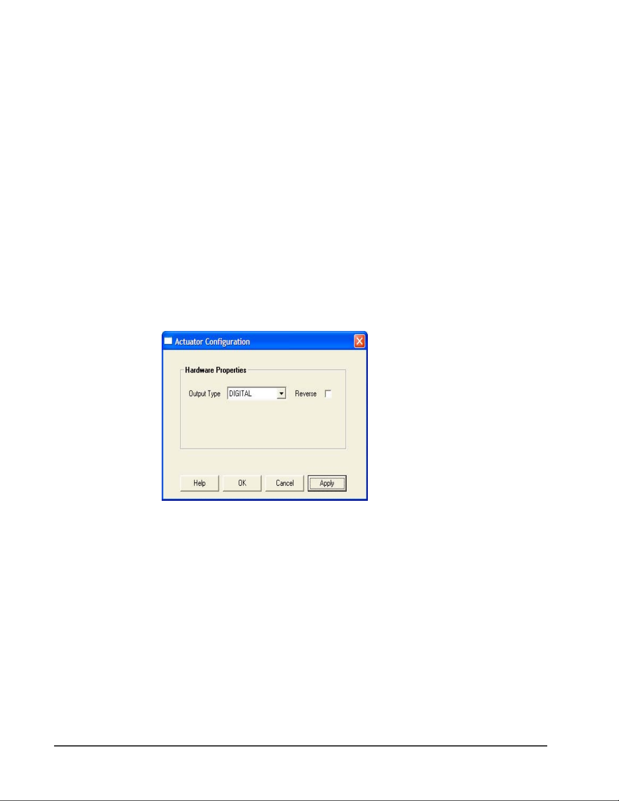
2. Select an output type. See Table 15 for a brief definition of the possible
selections.
3. If you want to assign an override value, select the box labeled Permit Override
and then enter an override value as a percentage of the total output value. If
you have chosen a digital output, such as FAN_SPEED_1, then the override
box changes to provide you with the option of ON or OFF for your override.
Note: Outputs are overridden by use of the Unit Ventilator Controller LONMARK
Object command. This command is available from the Object Manage
screen of the Unit Ventilator Controller configuration wizard. Click
Override ON to enable the override, and Override OFF to disable it.
4. Select the Local Hardware box if the output is connected to a physical actuator
such as a motor or valve.
5. Click Configure.
6. In the Output Type box (Figure 30), click the drop-down arrow and select the
output signal appropriate for your application. The output signal selection
presented to you is dependent upon the choice you made in Step 2. See the
Output Signal Types section for more information.
Figure 30: Hardware Output1
Note: Reverse Output - Normally , an output is ON when the output components
are supplying 100% of the rated voltage. If you want the output to supply
0% of the rated voltage when ON, select the Reverse box. For a digital
output, the output is normally ON when the contacts are closed. When you
reverse a digital output, the output is ON when the contacts are open.
You have now configured an output.
LX Series Unit Ventilator Controller User's Guide70
Page 71

Configuring an Output Represented as a Functional Block
To configure an output represented as a functional block:
1. Select the Hardware Output in the LX-UVL wizard and click the Launch
button. The Actuator wizard opens (Figure 31).
Figure 31: Hardware Output Configuration
2. In the Output Type box, select the type of output signal. See the Output Signal
Types section for more information.
Note: Reverse Output - Normally , an output is ON when the output components
are supplying 100% of the rated current and voltage. For a digital output,
the ON state occurs when the contacts are closed. If you want the output
when ON to supply 0% of the rated current and voltage or for the digital
contacts to be open, then select the Reverse box.
3. Enter an override value as a percentage of the total output to assign an override
value.
Note: Normally, digital outputs are closed at 100% and open at 0%. See the
preceding Reverse Output note. Outputs are overridden by use of the
actuator LONMARK Object command. This command is available from the
Object screen of the actuator wizard.
4. Enter a default value in the Default Value box.
The default values are used when the Unit Ventilator Controller is in the default
state. The Unit Ventilator Controller may enter the default state at startup. The state
that the Unit Ventilator Controller enters at startup is selected during
commissioning.
LX Series Unit Ventilator Controller User's Guide 71
Page 72

Heating-Cooling Configuration
On the heating-cooling configuration screen, you define:
• occupied, standby, and unoccupied setpoints in both heating and cooling mode
• maximum and minimum discharge temperatures
• economize maximum outdoor temperature and enthalpy
• change over delay
• mechanical cooling minimum operating times (Figure 32)
LX Series Unit Ventilator Controller User's Guide72
Page 73
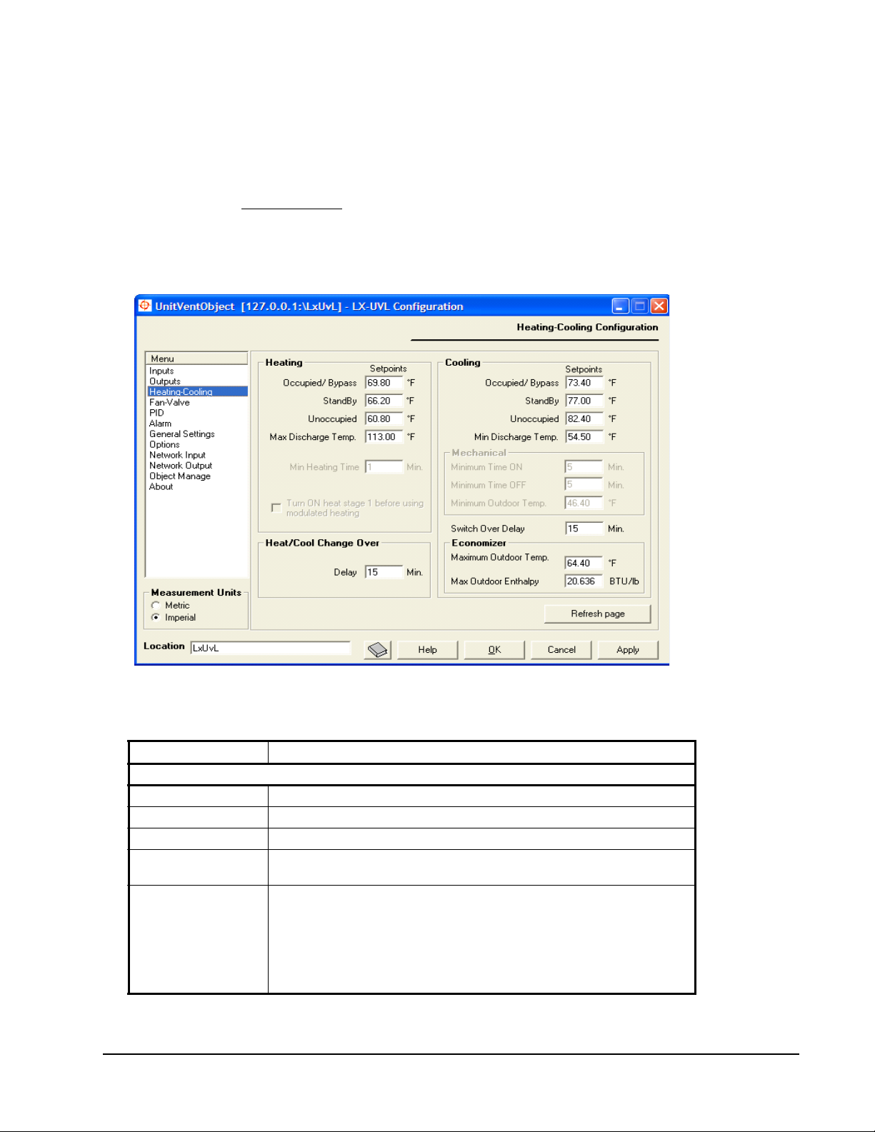
Optimum Start
Optimum Start prepares the space for occupancy in advance of the occupied
period. The Unit Ventilator Controller uses stored daily statistics to calculate the
length of time required each day to reach the occupied setpoints just as actual
occupancy begins.
See the primary Optimum Start section for more information.
Note: For Optimum Start to work, the network variable nviOccCmd must be set
to SNVT type SNVT_tod_event. You can set this using the Changeable Nv
Manager view of the device in FX Workbench.
Figure 32: Heating-Cooling Configuration Screen
Table 16: Heating-Cooling Configuration Parameters
Field Description
Heating
Occupied/Bypass
Standby
Unoccupied
Maximum Discharge
Temperature
Minimum Heating
Time
LX Series Unit Ventilator Controller User's Guide 73
Displays the heating setpoint for the occupied and bypass states.
Displays the heating setpoint for the standby state.
Displays the heating setpoint for the unoccupied state.
Displays the highest discharge air temperature you allow during the
heating state.
Displays the length of time that the duct and perimeter heating must stay
ON once it has turned ON, and the length of time that the heating must
stay OFF once it has turned OFF. Minimum heating time affects duct
heating, perimeter heating, and staged outp ut s. Once a st ag ed outp ut has
changed state, the next staged output cannot change state until the
minimum heating time has passed.
Note:
Minimum Heating Time does not apply to modulated heating.
Page 74

Table 16: Heating-Cooling Configuration Parameters
Field Description
T urn ON Heat Stage
1 before using
Modulated Heating
Cooling
Occupied/Bypass
Standby
Unoccupied
Minimum Discharge
Temperature
Mechanical
Minimum Time ON
Minimum Time OFF
Minimum Outdoor
Temperature
Switch Over Delay
Economizer
Maximum Outdoor
Temperature
Maximum Outdoor
Enthalpy
Heat/Cool Change Over
Heat/Cool Change
Over
This option normally applies to a situation where a gas-heating system
needs to energize a contact before modulating the gas-heating valve.
Enter the cooling setpoint for the occupied and bypass states.
Enter the cooling setpoint for the standby state.
Enter the cooling setpoint for the unoccupied state.
Enter the minimum temperature of the discharge air that you allow during
the cooling state.
Enter the minimum ON time for both heating and mechanical cooling.
Enter the minimum OFF time for mechanical heating and cooling.
Enter the minimum outdoor air temp erature at w hich mechanical co oling is
allowed. Mechanical cooling disables when the outdoor air temperature is
less than this value.
The time interval that must pass before m echanical cooling ca n occur after
free cooling or free cooling can occur after mechanical cooling.
Enter the value below which free cooling is permitted when only the
outdoor air temperature is available and not the outdoor humidity or
enthalpy.
Enter the value below which free cooling is permitted when only the
outdoor air enthalpy, and not the indoor air enthalpy, is available.
The time interval that must pass before heating can occur after cooling or
cooling can occur after heating.
Fan-Valve Configuration
On this screen, you select the type of fan input, fan operation, and floating valve
operating properties (Figure 33).
LX Series Unit Ventilator Controller User's Guide74
Page 75

Figure 33: Fan-Valve Configuration Screen
Table 17: Fan-Valve Configuration Parameters
Field Description
Fan
Fan Speed Allows your sensor to measure the fan speed.
Fan Current Allows your sensor to measure the current
drawn by the fan.
Current Threshold Sets the current at which you consider the fan
Minimum Speed Displays the fan minimum speed.
ON/OFF Period Displays the period of time that must pass
Always ON in Occupied Mode Forces the fan to run continuously during
Digital Valves
Minimum ON/OFF Period Displays the period of time that must pass
Valve
Minimum Position Displays the valves, minimum position when
Drive Time for Floating Valves Displays the period of time required for the
to be ON. This affects the alarm that compares
the states of the fan input and fan output.
before the fan can turn ON after turning OFF; or
the fan can turn OFF after turning ON.
occupied mode. If this box is not checked, the
fan runs only when there is a heating or cooling
demand.
before the fan can turn ON after turning OFF, or
the fan can turn OFF after turning ON.
there is a heating or cooling demand. The
valves are fully closed when there is no heating
or cooling demand.
valve to move from the fully closed to the fully
open position.
LX Series Unit Ventilator Controller User's Guide 75
Page 76

PID Configuration
The Unit Ventilator Controller uses as many as five PID Loops to control the space
temperature, discharge temperature, CO2 level, and humidity.
Figure 34: The PID Configuration Screen
Table 18 applies to the space temperature, discharge temperature, CO2 level, and
humidity loops.
Table 18: PID Configuration Parameters
Field Description
Proportional Gain Enter the gain per unit of the error.
Integral Gain Enter the gain per unit of the error.
Integral Time Enter the error repetitively sampled, and the integral gain is added to the
output. The period of time between samples is the integral time. Enter the
integral time for your process.
Derivative Gain Enter the gain per unit of the error.
Derivative Time Enter the derivative time–the time between two samples of the error. The
Deadband Enter a number to define the size of the deadband. The deadband is a
Use Supply Air
Temperature Only
for Limitation
two samples are compared to find the change in the error.
range of values symmetrical about the setpoint. See the Deadband
section for more information.
Allows the Unit Ventilator Controller to control the unit with the room
demand, and limits the discharge temperature between the minimum and
maximum discharge temperature.
If this option is unchecked, the Unit Ventilator Controller tries to maintain
the calculated discharge temperature setpoint. The discharge setpoin t is
calculated with a linear equation between the minimum and maximum
discharge air temperature and the space PID loops.
LX Series Unit Ventilator Controller User's Guide76
Page 77

Alarm Configuration
On this screen, you can set the alarm high and low limits, offset, and alarm delays
(Figure 35).
Figure 35: Alarm Configuration
Alarms monitor network variables or control points. These variables or points are
called monitored variables. When a monitored variable has a value that causes an
alarm message to be transmitted, then the monitored variable is in the alarm state.
Table 19 describes the alarm configuration parameters.
Table 19: Alarm Configuration Parameters
Field Description
Alarm Delay Enter the length of time that an input must be in the alarm state before an alarm
sounds.
Alarm Offset Enter the amount of deviation from the setpoint that causes an alarm to sound.
Alarm Low
Limit
Alarm High
Limit
Enter a value at which the alarm becomes active. The alarm becomes active
when the monitored variable falls below this value.
Enter a value at which the alarm becomes active. The alarm becomes active
when the monitored variable rises above this value.
Space and Return Temperatures and Humidity
Space and Return Temperature and Humidity alarms have an alarm delay and an
alarm offset only. In this case, the alarm becomes active when both of the
following conditions are present:
• The monitored temperature is outside of the range bounded by the setpoint plus
or minus the alarm offset.
LX Series Unit Ventilator Controller User's Guide 77
Page 78

• This preceding condition exists for a length of time greater than the alarm
delay.
CO2 Levels
While this alarm uses an offset, the alarm only sounds when the following
conditions are present:
• The CO2 concentration is greater than the setpoint + the offset.
• This preceding condition persists for a length of time greater than the alarm
delay.
An alarm does not sound when the CO2 concentration is less than the
setpoint - the offset.
Discharge Temperature and Auxiliary Alarm
Both the Discharge Temperature and Auxiliary alarms have an alarm delay and
high and low limit. In this case, the alarm becomes active when both of the
following occur:
• The monitored temperature is outside of the range marked by the high and low
limits.
• This preceding condition exists for a length of time greater than the alarm
delay.
Mixed Air Temperature
Mixed air temperature alarm protects the cooling coils from freezing. The alarm
becomes active when both of the following conditions are present:
• The monitored temperature is less than the low limit.
• This condition exists for a length of time greater than the alarm delay.
Fan Alarm
The Fan alarm applies to the fan state only. The fan alarm becomes active when
one of following conditions occurs for a time period greater than the alarm delay:
• The fan command is ON, and the fan input differs from the fan output, or the
fan current is lower than the fan current threshold, or
• The fan command is OFF, and the fan input differs from the fan output, or the
fan current is higher than the fan current threshold.
Whether a digital fan speed is ON or OFF, a decision is made by monitoring the
fan speed or fan current. The alarm delay must be long enough to allow the fan to
reach the ON or OFF stage. The fan speed or fan current level is set in the
Fan-Valve Configuration screen.
LX Series Unit Ventilator Controller User's Guide78
Page 79

Similarly, a variable speed fan requires time to speed up or slow down so that its
speed matches the output. The alarm delay must be long enough to allow the fan to
reach its commanded speed; otherwise, false alarms generate.
General Settings Configuration
Figure 36 shows the General Settings Configuration screen.
Figure 36: General Settings Configuration Screen
Table 20: General Settings Parameters
Field Description
Fresh Air Minimum
Input
Damper Position Select the Damper Position and enter a percentage value in the box
Air Volume Select Air Volume and enter a percentage to for a minimum amount
Damper Drive Time Enter the time required for the damper drive to move the damper
Select either Damper Position or Air Volume. If you are not using the
fresh air damper, the minimum input area is not applicable and
remains in gray text.
below Minimum Input. The percentage value sets the minimum fresh
air intake. The damper opens as least as much as that value during
occupied mode. Fully open is 100% and fully closed is 0%.
of fresh air. The fresh air minimum is calculated using return air
temperature, mixed air temperature, and outside air temperature.
from fully open to fully closed.
LX Series Unit Ventilator Controller User's Guide 79
Page 80

Table 20: General Settings Parameters
Field Description
Terminal Load Output
Type
Bypass Time Enter the bypass time. Bypass time is the duration of bypass mode
CO
Limit Enter the maximum CO2 concentration that will occur before the UV
2
Emergency Contact
Input Action
Mixed Air Temperature
Low Limit
Select either option to include or exclude the economizer in the
terminal load calculations. If the economizer is not included, the fresh
air dampers modulate first; and when they are fully open, the
terminal load is calculated from 0. This is used for power
consumption monitoring. See Terminal Load section.
which begins when the bypass button is pressed in unoccupied or
standby mode. Remember that bypass time does not limit a bypass
period commanded by nviOccCmd.
allows fresh air into the duct .
Select the action to occur when the emergency contact is closed-
emergency purge or emergency shutdown. See the Emergency
Operation section for more information on these modes.
Enter the lowest temperature that you allow the mixed air to reach.
Mixed air temperature low limit is used to control the fresh air
damper.
If a CO
works to maintain low CO
minimum temperature. For more information see Figure 15.
sensor is used to control the fresh air damper, the controller
2
concentrations while keeping the
2
Radiation Heating
Radiation heating provides you with the ability to start heating outputs without
starting the heat pump fan. Hot air mixes with the room air by natural convection.
When you are not using the heating outputs, the option appears as gray text.
Table 21 provides further information on Radiation Heat parameters.
Table 21: Radiation Heat Parameters
Field Description
Permit Valve
Radiation Heating
Permit Local
Radiation Heating
Heat Order During
Unoccupied Mode
When selected, it enables the valve heating outputs to start on a
heating demand before the fan starts. If this option is not selected, and
the fan is not ON, the valve heating outputs remain OFF.
When selected, it enables the local heating outputs to start on a
heating demand before the fan starts. If this option is not selected, and
the fan is not ON, the local heating outputs remain OFF.
This enables you to select your unoccupied heating order: Radiation
First, Ventilation Only.
If you select Radiation First, the valve and/or heating outputs start first
on a heating demand. If the option Ventilation Only is selected, the fan
must be ON in order to start any heating outputs.
LX Series Unit Ventilator Controller User's Guide80
Page 81
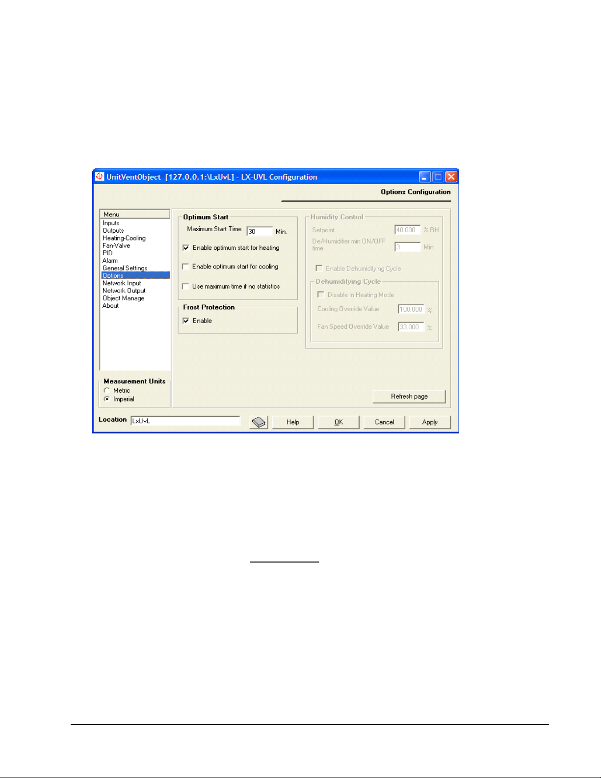
Options Configuration
On the Options Configuration screen (Figure 37) you can perform the following
tasks:
• Configure Optimum Start
• Configure Humidity Control
• Enable Frost Protection
Figure 37: Options Configuration Screen
Optimum Start
Optimum Start prepares the space for occupancy in advance of the occupied
period. The UVC uses stored daily statistics to calculate the length of time required
each day to reach the occupied setpoints just as actual occupancy begins.
Optimum Start is described in the Optimum Start section.
Note: For Optimum Start to work, the network variable nviOccCmd must be set
to SNVT type SNVT_tod_event. Use the Changeable Nv Manager view of
the device in FX Workbench to change the SNVT type.
LX Series Unit Ventilator Controller User's Guide 81
Page 82

Table 22: Options Configuration
Field Description
Maximum Start Time Set the maximum length of time before the start of occupancy
Enable Optimum Start for
Heating
Enable Optimum Start for
Cooling
Use Maximum Start Time if
No Statistics
mode that the Unit Ventilation Controller can start to heat or cool
the space.
Allow the Unit Ventilation Controller to heat the space so that the
space temperature is within the occupied setpoints when the
occupied period begins.
Allow the Unit Ventilation Controller to cool the space so that the
space temperature is within the occupied setpoints when the
occupied period begins.
Allow the Unit Ventilation Controller to use the maximum start
time as the length of time needed to heat or cool the space
before occupancy. Once Optimum Start statistics have been
recorded, the LX-UVL Controller uses Optimum Start time
periods calculated from the statistics. The Maximum Start Time is
only used to limit the length of the Optimum Start Time.
Bit 58 of the UCPTobject Options when set enables this option.
If this box is not selected, the Unit Ventilation Controller begins to
heat or cool the space at the beginning of the occupied period.
After the first start, it heats or cools the space at the recorded
Optimum Start time. After the second start, it heats or cools the
space at the calculated Optimum Start time.
Frost Protection
Select the Frost Protection box to have the heat turned ON at a space temperature
of 43°F (6°C) and turned off at 46°F (8°C). The heat can turn ON independently of
the temperature control. For example, the heat turns ON when nviApplicMode is
set to HVAC_OFF.
The heat turns ON in the order determined by the heating order.
Humidity Control
You can control Humidity many ways in the Unit Ventilation Controller; with a
cooling coil, a humidifier or a dehumidifier. Table 23 describes the Humidity
Control.
Table 23: Humidity Control
Field Description
Setpoint Enter the space humidity setpoint in percent.
Humidifier/Dehumidifier
Minimum ON/OFF Time
Enable Dehumidifying Cycle Enables the dehumidifier using the cooling coil.
Disable in Heating Mode Disables the dehumidifier using the cooling coil in heating
Enter the period of time that must pass before the humidifier or
dehumidifier can turn ON after turning OFF, or turn OFF after
turning ON.
Note: Humidifier/Dehumidifier ON/OFF time does not apply to
modulated humidifier and dehumidifier outputs.
mode.
LX Series Unit Ventilator Controller User's Guide82
Page 83

Table 23: Humidity Control
Field Description
Cooling Override Valu e Enter the minimum value for the cooling internal control loop. In
Fan Speed Override Value Enter the value for the fan speed in dehumidification mode. If
dehumidification process, this is the smallest value for the
cooling outputs. For example, if you have one modulating
cooling valve and the value for the cooling override is 55%, the
valve always opens at 55% or more in dehumidification mode.
you have 3 fan speeds, and you want speed 2 to be open,
enter the value 66.66%, which corresponds to 2 fan speeds on
a 3 fan speed possibility (2/3).
Network Input Configuration
Figure 38 shows the network input configuration screen. Table 24 describes the
parameters.
Figure 38: Network Input Configuration Screen
Table 24: Network Input Parameters
Field Description
Heartbeat Sets the maximum time between updates for the associated network input.
Persistent Allows the network variable to remain in memory after a power failure and/or
When the heartbeat interval has passed without an update, the network input
enters the heartbeat failure state, and its value becomes invalid.
reset. Do not make frequently changing network variables persistent.
Heartbeat Alarms
An alarm occurs if the period between received values of these variables exceeds
the value you enter into the Heartbeat column. For more information, see the
Alarm Operation
LX Series Unit Ventilator Controller User's Guide 83
section.
Page 84

Network Output Configuration
The network outputs screen enables you to control network traffic to reduce
network congestion while transmitting data as quickly as is necessary for your
application.
The network outputs screen enables you to control the frequency of network
variable transmissions through several different parameters. On the Network
Outputs Configuration screen, you can configure:
• heartbeat period for network outputs
• Send on Delta quantity
• throttle settings for several network outputs
You can also set the maximum send time and minimum send time for all other
network variables (Figure 39).
Figure 39: Network Output Configuration Screen
LX Series Unit Ventilator Controller User's Guide84
Page 85

Table 25: Network Output Configuration Parameters
Field Description
Heartbeat The maximum time period betwee n transmissions of the network
Send on Delta Enter the amount of change of the value of the network variable that
Throttle Enter the minimum time period that must pass before a network variable
General The values entered in the General box affect all other network variables
Maximum Send Time Enter the maximum time between transmissions of network variables.
Minimum Send Time Enter the minimum time between transmissions of network variables.
variable.
must occur before the variable is transmitted. The network variable is
transmitted whenever this much change occurs.
is transmitted.
not listed here.
Object Manage
The Object Manage screen enables you to view the status of the LONMARK object
and to use the LONMARK commands. To use the Object Manage screen, you must
configure the Unit Ventilator Controller and have it online and in communication
with the FX supervisory controller (Figure 40). Table 26 describes the parameters.
Figure 40: Object Manage
Object Status
Object Status messages are listed in the following sections with references to
tables describing the causes.
LX Series Unit Ventilator Controller User's Guide 85
Page 86

Table 26: Object Manage Parameters
Field Description
Device State Displays the current state of the LONMARK object.
Object Status Displ ays information from nvoUnitStatus. Messages, such as
Display Active Only If the box Display Active Only is selected, only the red active status
Get Status Refreshes status information for devices in the Object Status pane.
Clears Status Clears all status flags. This removes all messages. Clicking Get Status
Override ON Places the Unit Ventilator Controller into the override state. Control
Override OFF Ends controller override.
Enable Enables the controller after an override.
Disable Sets the L
Request Allows advanced users to query the LONMARK using the LONMARK
Communications Failure or Electrical Fault, may be displayed here. A
red icon indicates an active state and a gray icon indicates an inactive
state.
flags are shown. The Object Status area is blank when the UV is in its
normal state.
For a description of each of the Object Status pane messages, see
Object Status
retrieves new information. This can be used to check if a problem
condition is solved.
outputs including the network variables and linked hardware outputs
are set to their configured override value or state.
control outputs are at their configured disabled state.
object and commands.
To query the L
Select a command from the drop-down list beside the request button.
Click the Request button.
Requests are handled by SNVT_obj_request. Values for this SNVT
are given in Table 27.
.
ONMARK object to the disabled mode. In the disabled mode,
ONMARK object:
Table 27: Values for SNVT_obj_request
1
Value Identifier Meaning
0 RQ_NORMAL Enable object and remove override.
1 RQ_DISABLED Disable object.
2 RQ_UPDATE_STATUS Report object status.
3 RQ_SELF_TEST Perform object self test.
4 RQ_UPDATE_ALARM Update alarm status.
5 RQ_REPORT_MASK Report status bit mask.
6 RQ_OVERRIDE Override object.
7 RQ_ENABLE Enable object.
8 RQ_RMV_OVERRIDE Remove object override.
9 RQ_CLEAR_STATUS Clear object status.
10 RQ_CLEAR_ALARM Clear object alarm.
11 RQ_ALARM_NOTIFY_ENABLED Enable alarm notification.
12 RQ_ALARM_NOTIFY_DISABLED Disable alarm notification.
LX Series Unit Ventilator Controller User's Guide86
Page 87
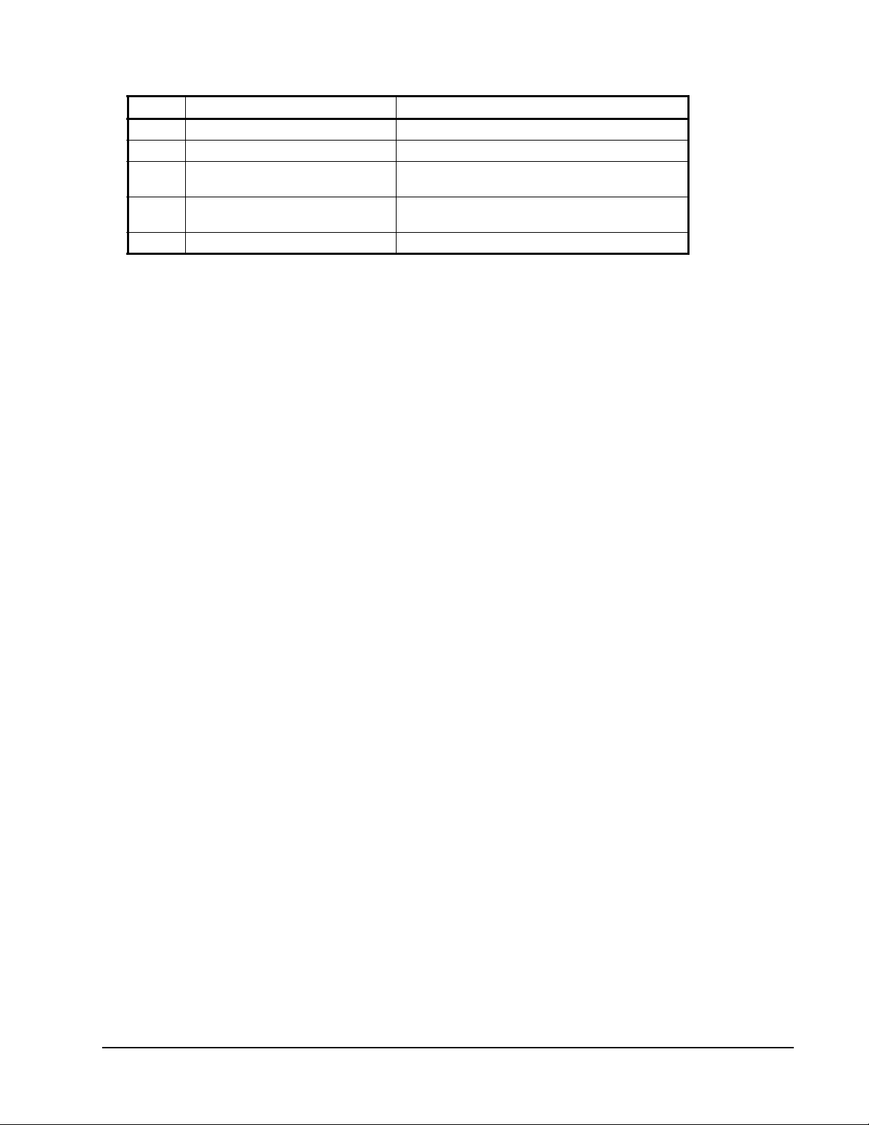
Table 27: Values for SNVT_obj_request
Value Identifier Meaning
13 RQ_MANUAL_CTRL Enable object for manual control.
14 RQ_REMOTE_CTRL Enable object for remote control.
15 RQ_PROGRAM Enable programming of special configuration
16 RQ_CLEAR_REST Clears the bit that indicates that the object has
17 RQ_RESET Resets the object.
1. Not all commands are available in the Unit Ventilator Controller.
1
properties.
been previously reset.
Communication Failure
This message results from a heartbeat failure on a network variable input that sets
the comm_failure bit of nvoStatus. See Table 11.
Electrical Fault
This message indicates that a local hardware sensor is disconnected. The
disconnect condition sets the electrical_fault bit of nvoStatus. See Table 12 for a
list of the possible disconnected sensors.
Out of Limits
This message indicates that a monitored point has exceeded limits set by the
operator who configured the device. The out-of-limits sets the out_of_limits bit of
nvoStatus. See Table 14.
Disabled
Active if you have disabled the device by pressing the Disable button.
In Alarm
Active if a communications failure or electrical fault has occurred or if any of the
conditions in the Alarm Configuration window have been met.
In Override
Active if you have placed the device into override by pressing the Override button.
Out of Service
Active when the UV controller cannot control the temperature in the zone of
control because it is not receiving a space temperature, or there is no slave input
(nviSlave).
Network Variables
The following text describes some of the most commonly used network variables
found in the Unit Ventilator Controller.
LX Series Unit Ventilator Controller User's Guide 87
Page 88
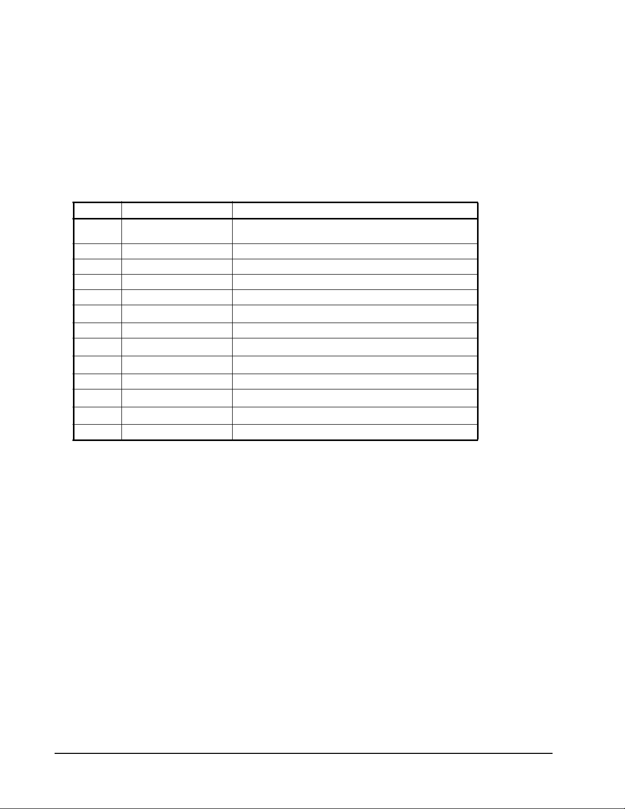
nviApplicMode
You can use this network variable input to coordinate the Unit Ventilator
Controller with the following devices:
• air handler controller
• any other supervisory controller
• human interface device
Type: SNVT_hvac_mode (108)
Table 28: nviApplicMode
Value Identifier Notes
0 HVAC_AUTO Controller automatically changes between appl ication
1 HVAC_HEAT Heating only.
2 HVAC_MRNG_WRMUP Application-specific morning warm up.
3 HVAC_COOL Cooling only.
4 HVAC_NIGHT_PURGE Application-specific night purge.
5 HVAC_PRE_COOL
6 HVAC_OFF Controller not controlling outputs.
7 HVAC_TEST
8 HVAC_EMERG_HEAT
9 HVAC_FAN_ONLY Air not conditioned, fan turned on.
10 HVAC_FREE_COOL
11 HVAC_ICE
0xFF HVAC_NUL Value not available.
modes.
1
Application-specific pre-cool
Equipment being tested
Emergency heat mode
Cooling with compressor not running
1
Ice-making mode
.
.
1
.
1
.
1
.
1. Not supported in the Unit Ventilator Controller.
nviCO2
Transmits CO2 level from a network device to the Unit Ventilator Controller.
Network values have priority over local sensor values.
Type: SNVT_ppm (29)
nviDischargeTemp
Transmits discharge temperature from a network device to the LX-UVL-1.
Network values have priority over local sensor values.
Type: SNVT_temp_p (105)
nviEconoEnable
This network variable input receives the economizer enable demand. When the
state and value are not set to zero, the economizer is enabled. When the state or
value is set to zero, the water state is disabled.
Type: SNVT_hvac_emerg
LX Series Unit Ventilator Controller User's Guide88
Page 89
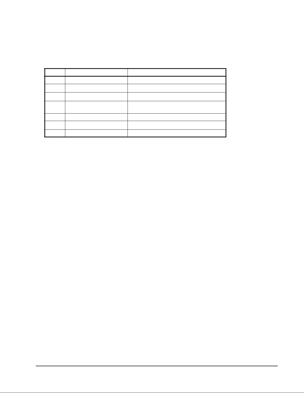
nviEmergCmd
Use this network variable input to command the UVC into different emergency
modes. It is typically set by a supervisory node. See Table 29.
Type: SNVT_hvac_emerg (103)
Table 29: nviEmergCmd
Value Identifier Actions
0 EMERG_NORMAL Normal operation.
1
1
2
3 EMERG_PURGE The damper moves to the fully open posi tion.
4 EMERG_SHUTDOWN Fan, heating, and cooling are turned OFF.
5
0xFF EMERG_NUL Value not available.
1. Not supported in the Unit Ventilator Controller.
EMERG_PRESSURIZE
EMERG_DEPRESSURIZE
EMERG_FIRE
1
The damper moves to the fully open position.
1
The damper moves to the fully closed position.
Fan, heating, and cooling are turned OFF.
---
nviExtCmdOutputx
These are numbered following the output number. For example,
nvoExtCmdOutput1, nvoExtCmdOutput2,.... These network variable inputs
receive the output signal, whether state and percentage to control any output that is
unassigned and configured through the actuator configuration wizard.
Type: SNVT_switch (95)
nviFanSpeedCmd
This network variable input receives the fan speed demand. It receives a value
between 0–100% and a state 0–1. If, for example, you have 3 fan speeds, fan speed
1 starts over 33%, fan speed 2 starts over 66% and fan speed 3 starts over 100%.
To start, the field state must be ON (1).
Type: SNVT_switch (95)
nviFanState
This network variable input receives the fan state. When state and value are not set
to zero, the fan state is considered ON. When state or value is set to zero, the fan
state is considered OFF.
Type: SNVT_switch (95)
LX Series Unit Ventilator Controller User's Guide 89
Page 90

nviHotWater
This network variable input receives the water state. Water state refers to whether
the water is hot or cold.
When state and value are not set to zero, the water state is hot. When state or value
is set to zero, the water state is cold.
Type: SNVT_switch (95)
nviMixedAirTemp
Used to receive the mixed air temperature. Network values have priority over local
sensor values.
Type: SNVT_occupancy (109) or SNVT_tod_event (128)
nviOccCmd and nviOccManCmd
This network variable input is used to command the Unit Ventilator Controller
object into different occupancy modes. See the Mode Selection section for more
information. Table 30 shows the possible values of nviOccCmd and
nviOccManCmd.
Type: SNVT_occupancy (109) or SNVT_tod_event (128)
Table 30: Values of nviOccCmd and Modes
Value Identifier Unit Ventilator Controller Mode
0 OC_OCCUPIED Occupie d Mode
1 OC_UNOCCUPIED Unoccupied mode
2 OC_BYPASS Bypass mode
3 OC_ST ANDBY S tandby mode
0xFF OC_NUL Invalid data
The network variable nviOccCmd commands the Unit Ventilator Unit Controller
to change modes according to the value of the variable. The value of nviOccCmd
itself can be changed by a network schedule or a manual change.
While in any mode, the UVC can enter a heating or cooling state as required to
maintain the space within the limits of the setpoints.
nviOutdoorEnth
Used to receive the outdoor enthalpy. Network values have priority over local
sensor values.
Type: SNVT_enthalpy (153)
nviOutdoorRH
Used to receive the outdoor air humidity. Network values have priority over local
sensor values.
Type: SNVT_lev_percent (81)
LX Series Unit Ventilator Controller User's Guide90
Page 91

nviOutdoorTemp
This network variable input receives the outdoor air temperature.
Type: SNVT_temp_p (105)
nviReturnTemp
Transmits return temperature from a network device to the UV. Network values
have priority over local sensor values.
nviSetPoint
Use this network variable input to change the temperature setpoints for the
occupied and standby modes via the network. The individual heating and cooling
setpoints for the occupied and standby modes are calculated from nviSetPoint. See
the The Effect of nviSetPoint on the Active Setpoints section.
Type: SNVT_temp_p (105)
nviSetPointOffset
Use this network variable input to shift the temperature setpoint by adding the
value of nviSetpointOffset to the current setpoint. This network variable operates
only on occupied and standby setpoints and does not affect the unoccupied
setpoint. See the The Effect of nviSetPoint on the Active Setpoints section.
Type: SNVT_temp_p (105)
nviShedding
Use this network variable input to reduce the Unit Ventilator Controller power
consumption. For example, if nviShedding is set to 25%, then heating and cooling
do not exceed 75%.
Type: SNVT_lev_percent (81)
nviSlave
Use this network variable input to force the Unit Ventilator Controller to follow the
demands of another unit ventilation controller. It is normally bound to the
nvoUnitStatus of the other Unit Ventilator Controller.
Type: SNVT_hvac_status (112)
nviSpaceEnth
Transmits space enthalpy from a network device to the UV. Network values have
priority over local sensor values.
Type: SNVT_enthalpy (153)
LX Series Unit Ventilator Controller User's Guide 91
Page 92

nviSpaceRH
This network variable input transmits space humidity from a network device to the
UVC. Network values have priority over local sensor values.
Type: SNVT_lev_percent (81)
nviSpaceTemp
Transmits space temperature from a network device to the Unit Ventilator
Controller. Network values have priority over local sensor values.
Type: SNVT_temp_p (105)
nviWaterTemp
Transmits water temperature from a network device to the Unit Ventilator
Controller. Network values have priority over local sensor values. If both
nviHotWater and nviWaterTemp are received from the network, nviHotWater has
priority over the nviWaterTemp.
Type: SNVT_temp_p (105)
nvoCtrlOutputx
These are numbered following the output number. For example, nvoCtrlOutput1,
nvoCtrlOutput2. These network variable outputs send the output signal, whether
state or percentage, to any actuators.
Type: SNVT_switch (95)
nvoDischargeSetPt
This network variable output sends the discharge setpoint in use by the unit
ventilator object.
Type: SNVT_temp_p (105)
nvoEconoEnable
This network variable output is used to monitor or send the enable or disable status
of the economizer. Economizer control is enabled when st ate and value fields are 1
and 100%, respectively . Economizer control is disabled when state and value fields
are set to zero.
Type: SNVT_switch (95)
nvoEffectSetPt
This network variable output sends the effective setpoint in use by the fan coil
object.
Type: SNVT_temp_p (105)
LX Series Unit Ventilator Controller User's Guide92
Page 93

nvoFanSpeed
This network variable output sends the fan speed.
Type: SNVT_switch (95)
nvoHwInputx
Numbered following the input number . For example, nviHwInput1, nvoHwInput2.
The network variable output sends the input value over the network with their own
changeable SNVT type.
Type: Changeable
nvoOccState
This network variable output sends the occupancy state used by the unit ventilator
object.
Type: SNVT_occupancy (109)
nvoUValarm
Table 31 describes the nvoUValarm parameters.
Type: SNVT_state_64 (165)
Format: UNVT_uv_alarms
Table 31: nvoUValarm (Part 1 of 3)
Programmatic Name Bit
Number
nviSpaceTempHeartBeat 0 Heartbeat failure reported from nviSpaceTemp.
nviApplicModeHeartBeat 1 Heartbeat failure has occurred in nviApplicMode.
nviSetPtOffsetHeartBeat 2 Heartbeat failure has occurred in nviSetPtOffset.
nviOccCmdHeartBeat 3 Heartbeat failure has occurred in nviOccCmd.
nviWaterTempHeartBeat 4 Heartbeat fa ilure has occurred in nviWaterTemp.
nviHotWaterHeartBeat 5 Heartbeat failure has occurred in nviHotWater.
nviSupplyTempHeartBeat 6 Heartbeat failure has occurred in nviSupplyTemp.
nviFanStateHeartBeat 7 Heartbeat failure has occurred in
nviEconEnableHeartBeat 8 Heartbeat failure has occured in nviEconEnable.
nviSheddingHeartBeat 9 Heartbeat failure has occurred in nviShedding.
nviSlaveHeartBeat 10 Heartbeat failure has occurred in nviSlave.
nviOutdoorTempHeartBeat 11 Heartbeat failure has occurred in nviOutdoorTemp.
nviSpaceRHHeartBeat 12 Heartbeat failure has occurred in nviSpaceRH.
nviOutdoorRHHeartBeat 13 Heartbeat failure has occurred in nviOutdoorRH.
nviCO2HeartBeat 14 Heartbeat failure has occurred in nviCO2.
nviReturnTempHeartBeat 15 Heartbeat failure has occurred in nviReturnTemp.
nviMixAirTempHeartBeat 16 Heartbeat failure has occurred in nviMixAirTemp.
nviSpaceEnthHeartBeat 17 Heartbeat failure has occurred in nviSpaceEnth.
Meaning When Bit Is Set
This network variable input transmits the water
state: hot or cold.
nviFanSpeedCmdState.
LX Series Unit Ventilator Controller User's Guide 93
Page 94

Table 31: nvoUValarm (Part 2 of 3)
Programmatic Name Bit
Number
nviOutdoorEnthHeartBeat 18 Heartbeat failure has occurred in nviOutdoorEnth.
nviFanSpeedCmdHeartBeat 19 Heartbeat failure has occurred in
nviExtCmdOutputxHeartBeat 20-26 Heartbeat failure has occurred in
SpaceTempSensorFault 32 Space temperature sensor is disconnected for
DischargeTempSensorFault 33 Discharge temperature sensor is disconnected for
ReturnTempSensorFault 34 Return temperature sensor is disconnected for
MixedAirTempSensorFault 35 Mixed air temperature sensor is disconnected for
OutdoorTempSensorFault 36 Outdoor temperature sensor is disconnected for
WaterTempSensorFault 37 Water temperature sensor is disconnected for
SetpointOffsetElecFault 38 Setpoint offset is disconnected for longer than
LowSpaceTemp 39 Space temperature is lower than the active heating
HighSpaceTemp 40 Space temperature is higher than the active
LowDischargeTemp 41 The discharge temperature is lower than the low
HighDischargeTemp 42 The discharge temperature is higher than the high
LowReturnTemp 43 The return temperature is lower than the active
HighReturnTemp 44 The return temperature is higher than the active
LowMixedAirTemp 45 The mixed air temperature is lower than the low
LowSpaceRH 46 The space humidity is lower than a setpoint by
HighSpaceRH 47 The space humidity is higher than a setpoint by
Meaning When Bit Is Set
nviFanSpeedCmd.
nviExtCmdOutput.
longer than 30 seconds.
longer than 30 seconds.
longer than 30 seconds.
longer than 30 seconds.
longer than 30 seconds.
longer than 30 seconds.
30 seconds.
setpoint by more than the offset for a time period
longer than the alarm delay.
heating setpoint by more than the offset for a time
period longer than the alarm delay.
limits setpoint for a time period longer than the
alarm delay.
limits setpoint for a time period longer than the
alarm delay.
heating setpoint by more than the offset and for
longer than the time specified in the alarm delay.
cooling setpoint by more than the offset and for
longer than the time specified in the alarm delay.
limit setpoints for longer than the time specified in
the alarm delay.
more than the humidity offset for a time period
longer than the alarm delay.
more than humidity offset for a time period longer
than the alarm delay.
LX Series Unit Ventilator Controller User's Guide94
Page 95

Table 31: nvoUValarm (Part 3 of 3)
Programmatic Name Bit
Number
HighCO2Level 48 The CO2 concentration is higher than the CO2 limit
FanStateMismatch 49 The fan state is different than the fan output for a
AuxiliaryLowAlarm 50 The auxiliary alarm input is lower than the low limit
AuxiliaryHighAlarm 51 The auxiliary alarm input is higher than the low limit
Emergency 52 The Heat Pump Unit Controller is in emergency
Meaning When Bit Is Set
by more than the amount defined in any CO
and for longer than the time defined in the alarm
delay.
time period longer than the alarm delay.
setpoint for a time period longer than the alarm
delay.
setpoint for a time period longer than the alarm
delay.
mode.
nvoUVstate
This network variable output sends the unit ventilator status. It provides the
configuration errors and mode status.
Type: SNVT_state_64 (165)
offset
2
Format: UNVT_uv_state
Table 32: nvoHPstate (Part 1 of 2)
Programmatic Name Bit
Number
OutofService 0 The device is out of service. There is no space
EmergencyMode 1 Emergency mode is ON. It is received from the
HotWater 2 The water is hot.
EconomizerEnabled 3 Economizer is enabled. This occurs when the
MecCoolingEnabled 4 Mechanical cooling is enabled. This occurs when
CtrlOutputxOverridden 8–14 The unit ventilator object output is overridden.
HwOutputxOverridden 15–21 The hardware output is overridden.
DupReturnTempCfgError 36 Duplicate return air temperature sensor
DupDischrgTempCfgError 37 Duplicate discharge air temperature sensor
DupOutTempTempCfgError 38 Duplicate outdoor air temperature sensor
DupMixAirTempCfgError 39 Duplicate mixed air temperature sensor
DupWaterTempCfgError 40 Duplicate water temperature sensor configuration
Meaning When Bit Is Set
temperature sensor configured, or nvislave is not
bound.
nviEmergCmd or sent by the emergency contact.
outdoor temperature is lower than the economizer
maximum outdoor temperature.
the outdoor temperature is higher than the
mechanical minimum outdoor temperature.
configuration error.
configuration error.
configuration error.
configuration error.
error.
LX Series Unit Ventilator Controller User's Guide 95
Page 96

Table 32: nvoHPstate (Part 2 of 2)
Programmatic Name Bit
Number
DupSpaceHumidCfgError 41 D uplicate space humidity sensor configuration
DupOutHumidCfgError 42 Duplicate outdoor humidity sensor configuration
DupSpaceEnthCfgError 43 Duplicate space enthalpy sensor configuration
DupOutEnthCfgError 44 Duplicate outdoor enthalpy sensor configuration
DupCO2LevelCfgError 45 Duplicate CO2 level sensor configuration error.
DupAuxAlarmCfgError 46 Duplicate auxiliary alarm sensor configuration
DupFanStateCfgError 47 Duplicate fan state sensor configuration error.
DupFanSpdSelCfgError 48 Duplicate fan speed selector sensor configuration
DupModeSelCfgError 49 Duplicate mode selector sensor configuration
DupOccCntctCfgError 50 Duplicate occupancy contact sensor configuration
DupBypassCntctCfgError 51 Duplicate bypass contact sensor configuration
DupWindowCntctCfgError 52 Duplicate window contact sensor configuration
DupEconoCntctCfgError 53 Duplicate economizer enabled contact sensor
DupEmergCntctCfgError 54 Duplicate emergency contact sensor configuration
FanSpeedCfgError 55 Fan speeds configuration error.
NoFanOutputCfgError 56 No fan output configuration error.
NoHeatOrCoolCfgError 57 No heat or cooling output configuration error.
HeatValveCfgError 58 Heating valve configuration error.
CoolValveCfgError 59 Cooling valve configuration error.
HeatCoolValveCfgError 60 Heating and cooling valve configuration error.
HeatStagesCfgError 61 Heating stages configuration error.
CoolStagesCfgError 62 Cooling stages configuration error.
RevValvWOCoolCfgError 63 Reversing valve without cooling stages
Meaning When Bit Is Set
error.
error.
error.
error.
error.
error.
error.
error.
error.
error.
configuration error.
error.
configuration error.
nvoSpaceTemp
This network variable output sends the space temperature used by the fan coil
object.
Type: SNVT_temp_p (105)
LX Series Unit Ventilator Controller User's Guide96
Page 97

nvoTerminalLoad
This network variable output sends the energy demand of the fan coil in
percentage. Positive values are cooling demand and negative values are heating
demand.
Type: SNVT_lev_percent (81)
nvoUnitStatus
This network variable output sends the following simultaneously:
• operating mode
• primary heating state as a percentage
• secondary heating state (if relevant) as a percentage
• cooling state as a percentage
• fan state as a percentage
• unit ventilator alarm state
Type: SNVT_hvac_status (112)
LX Series Unit Ventilator Controller User's Guide 97
Page 98

Standard Network Variable Types (SNVTs)
The following are some of the SNVTs more commonly used in the Unit V entilator
Controller configuration wizard.
SNVT_hvac_emerg (103)
HVAC Emergency Mode used for heating, ventilating, and air conditioning
applications.
Table 33: SNVT_hvac_emerg
SNVT_hvac_emerg Description
SNVT Index 103
Measurement emerg_t
Field Type Category Enumeration
Type Size 1 byte
Valid Type Range emerg_t
Type Resolution 1
Units N/A
Invalid Value EMERG_NUL
Raw Range emerg_t
Scale Factor N/A
File Name SNVT_EM.H
Default Value N/A
SNVT_hvac_mode (108)
Use for heating, ventilating, and air conditioning applications.
Table 34: SNVT_hvac_mode
SNVT_hvac_mode Description
SNVT Index 108
Measurement hvac_t
Field Type Category Enumeration
Type Size 1 byte
Valid Type Range hvac_t
Type Resolution 1
Units N/A
Invalid Value HVAC_NUL
Raw Range hvac_t
Scale Factor N/A
File Name SNVT_HV.H
Default Value N/A
LX Series Unit Ventilator Controller User's Guide98
Page 99

SNVT_hvac_status (112)
Use for heating, ventilating, and air conditioning applications.
Table 35: SNVT_hvac_status
SNVT_hvac_status Description
SNVT Index 112
Measurement HVAC Status
Field Type Category Structure
Type Size 12 bytes
Table 36: SNVT_hvac_status Structure
Field Measurement
mode hvac_t
heat_output_primary signed long
heat_output_secondary signed long
cool_output signed long
econ_output signed long
fan_output signed long
in_alarm unsigned short
Table 37: HVAC Status Mode
HVAC Status Mode Description
Field mode
Measurement hvac_t
Field Type Category Enumeration
Type Size 1 byte
Valid Type Range hvac_t
Type Resolution 1
Units N/A
Invalid Value HV_NUL
Raw Range hvac_t
Scale Factor N/A
File Name SNVT_HV.H
Default Value N/A
LX Series Unit Ventilator Controller User's Guide 99
Page 100
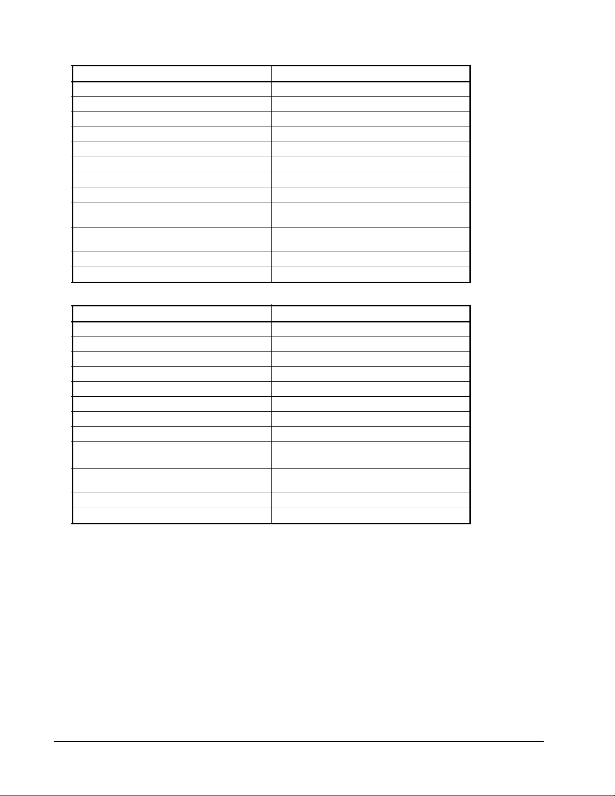
Table 38: Primary Heat Output
Primary Heat Output Description
Field Heat_output_primary
Measurement Primary Heat Output
Field Type Category Signed Long
Type Size 2 bytes
Valid Type Range -163.840 – 163.830
Type Resolution 0.005
Units Percent of full scale
Invalid Value 32,767 (0x7FFF)
Raw Range -32,768 – 32,766
0x7FFE
Scale Factor 5, -3, 0
File Name N/A
Default Value N/A
S = a*10b*(R+c)
Table 39: Secondary Heat Output
Secondary Heat Output Description
Field heat_output_secondary
Measurement Secondary Heat Output
Field Type Category Signed Long
Type Size 2 bytes
Valid Type Range -163.840 – 163.830
Type Resolution 0.005
Units Percent of full scale
Invalid Value 32,767 (0x7FFF)
Raw Range -32,768 – 32,766
0x7FFE
Scale Factor 5, -3, 0
File Name N/A
Default Value N/A
S = a*10b*(R+c)
LX Series Unit Ventilator Controller User's Guide100
 Loading...