

Page 1
ENGINEERING GUIDE
Water-Cooled
Self-Contained Units
L-Series, Vertical
FORM 145.05-EG2 (618)
Page 2
FORM 145.05-EG2 (618)
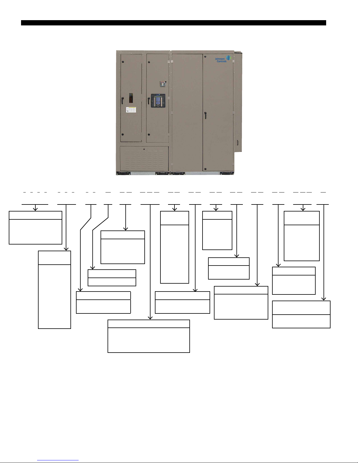
Nomenclature
1 2 3 4 5 6 7 8 9 10 11 12 13 14 15 16 17 18 19 20 21 22 23 24 25 26 27 28 29 30 31
L S W U 0 9 5 S E A 4 6 S P D 4 0 O H 3 6 P 2 V V C O 0 0 0 S
UNIT TYPE
L = “L” Series
S = Self-Contained
W = Water-Cooled
U/D = Upflow/Downflow
NOMINAL
CAPACITY
025 = 25 Ton
032 = 32 Ton
035 = 35 Ton
040 = 40 Ton
050 = 50 Ton
060 = 60 Ton
062 = 62 Ton
070 = 70 Ton
080 = 80 Ton
095 = 95 Ton
105 = 105 Ton
SUPPLY VOLTAGE
17 = 208V-3-6-0
28 = 230V-3-6-0
46 = 460V-3-6-0
58 = 575V-3-6-0
DESIGN SEQUENCE
A = Initial Design
EVAPORATOR COIL
SE = Standard Efficiency
HE = High Efficiency
POWER SUPPLY CONNECTION
SPT = Single Point Terminal Block
SPD = Single Point Disconnect Switch
DPT = Dual Point Terminal Block
DPD = Dual Point Disconnect Switch
SUPPLY
MOTOR HP
05 = 5 HP
07 = 7.5 HP
10 = 10 HP
15 = 15 HP
20 = 20 HP
25 = 25 HP
30 = 30 HP
40 = 40 HP
50 = 50 HP
60 = 60 HP
SUPPLY MOTOR TYPE
OP = ODP Premium Eff.
TP = TEFC Premium Eff.
FAN SIZE
25 = 25 inch
28 = 28 inch
32 = 32 inch
36 = 36 inch
40 = 40 inch
FAN CLASS
P2 = CL2, Plenum
P3 = CL3, Plenum
VFD OPTION
CV = Constant Volume
VV = Variable Air Volume
(VAV )
VB = VAV with Bypass
ELECTRIC
HEAT SIZE
000 = No EH
017 = 17.5 KW
035 = 35 KW
052 = 52.5 KW
070 = 70 KW
105 = 105 KW
HEAT OPTION
CO = Cooling Only
HW = Hot Water
EH = Electric Heat
ENTERING WATER
TEMPERATURE
S = Standard Temperature
H - High Temperature
2
JOHNSON CONTROLS
Page 3

FORM 145.05-EG2 (618)
Table of Contents
FEATURES AND BENEFITS .................................................................................................................................... 5
FEATURES AND OPTIONS .................................................................................................................................... 11
SELECTION PROCEDURE .................................................................................................................................... 15
OPERATING LIMITATIONS .................................................................................................................................... 18
PHYSICAL DATA .................................................................................................................................................... 19
COOLING PERFORMANCE DATA ........................................................................................................................22
DIMENSIONAL DATA ............................................................................................................................................. 33
AIR PRESSURE DROPS ........................................................................................................................................ 57
SUPPLY FAN DATA ................................................................................................................................................ 63
WATER PRESSURE DROP .................................................................................................................................... 65
ELECTRICAL DATA ............................................................................................................................................... 68
OPERATING WEIGHTS .......................................................................................................................................... 69
GUIDE SPECIFICATIONS ...................................................................................................................................... 71
JOHNSON CONTROLS
3
Page 4

FORM 145.05-EG2 (618)
THIS PAGE INTENTIONALLY LEFT BLANK.
4
JOHNSON CONTROLS
Page 5

Features and Benefits
LOW OWNERSHIP COST
Lower Installation Cost
• Single point power connections.
• Single condenser water inlet and outlet connections. Factory installed internal piping.
• Comprehensive factory testing of refrigerant, condenser water piping, supply fan,
and control system.
• Factory installed internal condensate drain connection.
• Compact design allows smaller mechanical equipment room.
• Optional low service clearance units allow installation in even smaller mechanical
equipment rooms.
FORM 145.05-EG2 (618)
• Optional multiple piece shipment allows installation in tight spaces. No eld refrigerant or water piping is required.
• Condenser water piping connections from the top of the unit minimizes piping in
mechanical equipment room.
LOWER OPERATING COST
Efficient Operation
• Plenum fan with backward inclined airfoil blades provides required airow at a low-
er energy consumption compared to the most competitive units.
• All scroll compressors combined with highly efcient condenser and evaporator coil
design provides efcient cooling, lowering energy consumption.
• Water economizer and air economizer options provide free cooling to reduce power
consumption.
• Partial occupancy on any oor reduces power consumption, due to multiple compressor operation and optional variable frequency drive (VFD) to match capacity to
the load.
• After hours operation on any oor only requires unit on that oor with partial op-
eration of cooling tower and pumps. This saves signicant amount of energy over
chilled water systems.
• Variable condenser water ow option, with internal actuated valve(s), prevents ow
• Evaporator coil circuiting supports low leaving air temperature designs to reduce
• High efciency evaporator coil available for lower air ow, low leaving air tempera-
JOHNSON CONTROLS
through units not requiring cooling, saving pump energy.
design air ow and reduce fan operating energy.
ture applications.
5
Page 6

FORM 145.05-EG2 (618)
Features and Benefits (Cont’d)
Easier Maintenance
• Large, intuitive operator interface makes for quick set up and easier diagnostics. It is
on the external panel for easy viewing.
• Operator interface for optional VFD on the external panel.
• Easy access to important components through hinged doors for easy maintenance.
• Easily accessible components out of the air stream allow adjustment of components,
including expansion valves, while unit is operating.
• Easy lter access for inspection, removal, and replacement.
• Internally trapped condensate drain cleanout with easy access.
• Available BACnet® communications with Building Automation System (BAS) allows for easier control of larger installations.
• Emergency stop input.
Indoor Air Quality
• Condensate drain pan sloped in all directions to the drain point.
• Stainless steel drain pan standard
• High efciency lters option with pre-lters.
• Evaporator and waterside economizer coils surface may be cleaned from air entering
side as well as air leaving side.
• Easy access to internally trapped condensate drain cleanout.
• Matt faced berglass insulation.
Quieter Acoustic Performance
• Plenum fan with backward inclined airfoil blades provides required airow at a low-
er sound power level compared to the most competitive units.
• Unique placement of internal components minimizes amount of acoustic energy
leaving the unit.
• Supply fan and motor assembly mounted on a frame and isolated with springs.
• Optional discharge plenum congurations allow horizontal supply air discharge,
minimizing the outlet sound and pressure losses.
• Optional inlet plenum conguration minimizes sound escaping the unit inlet.
• Multiple scroll compressors, due to their smoother ow and stepped operation, mini-
mize the sound associated with the refrigerant system.
• The compressors are located out side air stream, including all the refrigerant piping
and condenser water piping.
6
JOHNSON CONTROLS
Page 7
FORM 145.05-EG2 (618)
STANDARD FEATURES
Controls
• Microprocessor based control system proven algorithms.
• Large 32-key operator interface with large display, in clear language, accessible
without opening panel.
• Alarms and faults displayed and stored in the controller memory.
• Occupied and Unoccupied mode operation.
• Timed Override operation.
• Supply airow proving switch.
• Condensing pressure control when condenser valves are present.
• All refrigerant controls like thermostatic expansion valves, sight glass are out of the
air stream and adjustable while unit is working.
• ETL and CETL listing for US and Canada.
Refrigerant Circuits
• Multiple scroll compressors for better temperature control. Up to six compressors.
• All compressors have independent refrigerant circuits and independent short circuit
protection.
• Automatic compressor lead-lag on units larger than 40 tons.
• Environmentally friendly R-410A refrigerant.
• Completely factory piped, charged, and protected refrigerant circuits.
• Each refrigerant circuit with suction and discharge pressure transducers for enhanced
diagnostics and control.
• Evaporator coil frost protection
• Mechanically cleanable shell and tube condenser, factory tested and piped.
• Factory leak and pressure tested refrigerant piping
• Low ambient compressor lockout.
Supply Fan
• Plenum fan with backward inclined airfoil blades provides required airow at lower
energy consumption and sound compared to the most competitive units.
• Minimum class II fans for high static requirements. Class III fans available.
• Supply fan and motor assembly is isolated with springs to minimize the vibration and
• Bearing lubrication line brought to one location for easy maintenance.
JOHNSON CONTROLS
sound transmission to the rest of the unit and beyond.
7
Page 8

FORM 145.05-EG2 (618)
Features and Benefits (Cont’d)
Unit Cabinet
• Welded base made out of 10-gauge galvanized steel frame and structural members.
• External cabinet parts made out of painted 16-gauge galvanized steel.
• External panels made out of painted 18-gauge galvanized steel.
• Lifting lugs to lift the unit without skid.
• Hinged 2-inch thick access doors covering the coil, compressors, condensers, water
piping, electrical components, and fan access. Insulated where necessary with 2-inch
matt faced berglass insulation.
• Stainless steel drain pan with insulation, sloped in all directions.
• Condensate drain with cleanout and proper slope towards the drain.
Filters Section
• Filter section made out of 18-gauge painted galvanized steel.
• 4-inch thick MERV 8 lters are standard.
Condenser Water Piping
• Factory installed and tested condenser water piping.
• Condenser water piping exiting unit from the top for easier and shorter eld connec-
tions.
OPTIONAL FEATURES
Variable Frequency Drive (VFD)
• Factory installed, wired, and commissioned VFD controls the fan speed in conjunction with the unit controller, based on a signal from controller.
• Unit installed duct static pressure sensor to sense duct static using elds installed
pneumatic tubes.
• Optional manual electrical bypass manually enables unit to run the supply fan motor
at full speed in case the VFD failure.
Waterside Economizer
• Waterside economizer, which uses colder condenser water available during colder
outdoor conditions, to provide cooling by passing cold condenser water through ad-
ditional water economy coil upstream of the evaporator coil in terms of air ow.
Internal temperature sensors determine suitability of condenser water for full or partial free cooling and route condenser water flow through the water economy coil
when suitable. Internal water piping and valves are included.
• Water economy coil with optional mechanically cleanable return bends is available.
• Condenser water ow through the unit is enabled only in cooling mode. Minimum
condenser water temperature for unit compressor operation in this mode is 40.0°F.
8
JOHNSON CONTROLS
Page 9

FORM 145.05-EG2 (618)
Condenser Water Regulating Valves
• Units without waterside economizer will permit compressor operation up to 55.0°F
and above. For condenser water temperatures below this threshold, optional condenser water regulating valve(s) are available. Optional condenser water valve con-
trols the water ow though unit condensers to maintain minimum discharge pressure
for all compressors with ow through unit enabled only in the cooling mode.
Optional Condenser and Bypass water valves maintain minimum discharge pressure
for all compressors with flow through unit always enabled.
Heating
• Hot water coil with factory installed and tested water piping and valve for modulated
control. Controlled by the unit controller.
• Electric heat, factory installed, wired, and tested.
• All of the heating options are in reheat position. However, the heating will only be
used when cooling is off.
• Only one heating option is available in any unit.
Controls
• Factory installed and wired non-fused disconnect switch for the unit power. Disconnect switch is accessible without opening unit doors.
• Static pressure transducer is installed and wired on all variable air volume (VAV)
units to control VFD operation.
• Additional static pressure transducer installed and wired with comparative logic built
in.
• Duct static pressure limit switch mounted and wired in unit to disable unit operation
in case of high duct static.
• BACnet (MS/TP) interface for communication with BAS.
• Water Flow Switch will lock out all compressors in the unit if minimum water ow
is not present.
High Efficiency Air Filtration
• Optional High Efciency MERV 13 4-inch thick lters are available with 4-inch
thick MERV 8 pre-lter.
High Efficiency Evaporator Coils
• High efciency evaporator coil for lower air ow, low leaving air temperature applications. Provides higher EER and higher capacity.
Modular Construction
• Unit shipped in multiple sections. All refrigerant piping, condenser water piping, and
JOHNSON CONTROLS
condensate drain piping is factory assembled and does not require additional eld
work. Various sections are as follows:
• Refrigerant and heating section consisting of evaporator coil, water economy
coil, condensers, compressors, condenser water piping, and heating options.
9
Page 10

FORM 145.05-EG2 (618)
Features and Benefits (Cont’d)
• Fan and power section consisting of supply fan and motor assembly, power and
control panels, and VFD.
• Filter section, including the filters.
Low service clearance
• For areas with limited mechanical equipment room space, optional conguration of
the unit requiring less (3 inch) than standard clearance on left of the unit as looking
at the unit from the fan side is required. Less (3 inch) service clearance on the fan
side is also available.
Field Installed Accessories
• Discharge plenum/Outlet plenum.
• Full discharge plenum is factory manufactured discharge plenum with 3-inch
thick matt faced insulation and 20-gauge perforated galvanized steel liner, with
or without factory cut openings.
• Half discharge plenum is factory manufactured discharge plenum with 3-inch
thick matt faced insulation and 20-gauge perforated galvanized steel liner, with
or without factory cut openings.
• Airside economizer with outdoor air connection, damper, and damper actuator at the top,
return air connection, damper, and damper actuator at the back. Provided with connecting
harness for the actuators and sensors, installed by others. Different control options:
• Dry bulb
• Single enthalpy
• Dual enthalpy
• Inlet sound attenuating plenum attaches to the lter section for further reducing the
sound emitted through the unit air inlet.
10
JOHNSON CONTROLS
Page 11
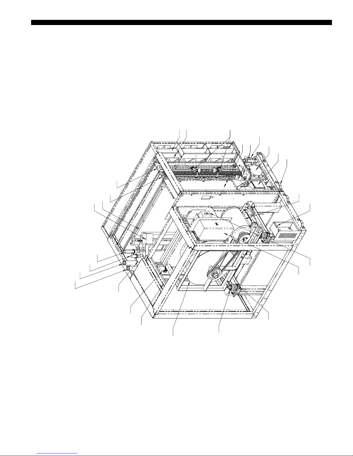
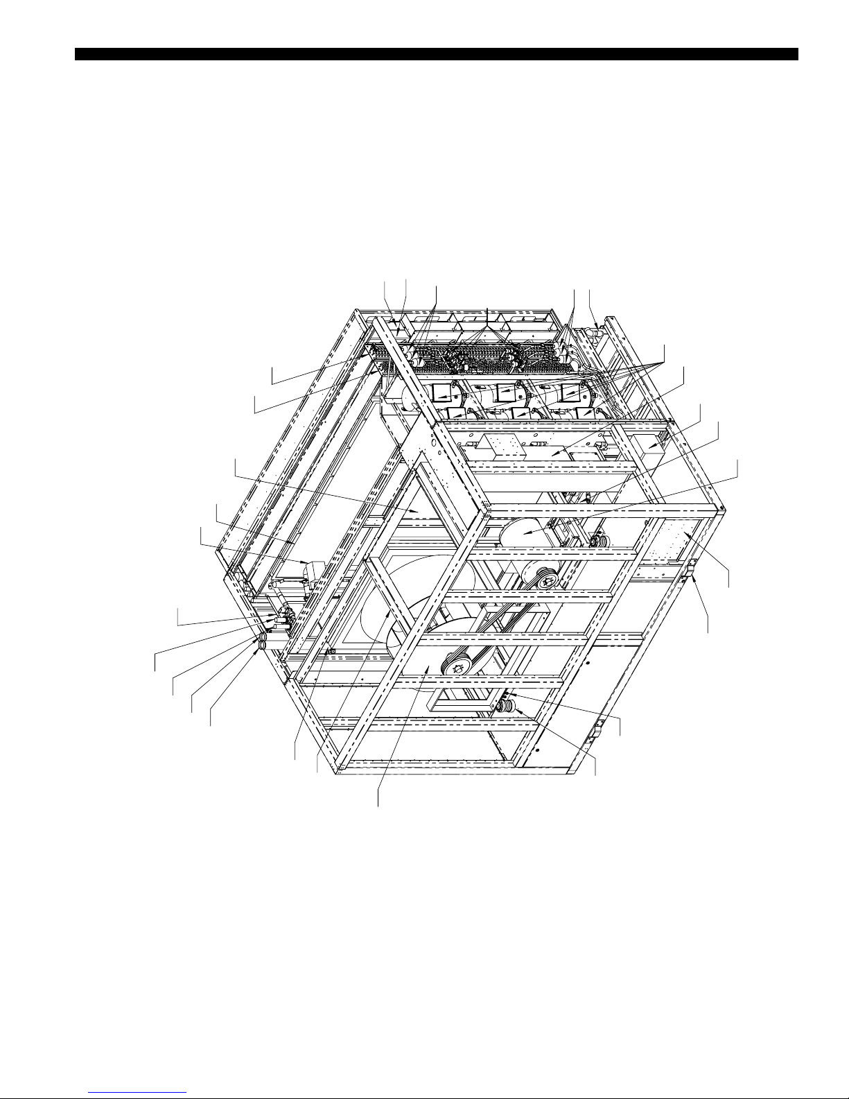
Features and Options
**OPTIONAL HOT WATER OR
ELECTRIC HEAT
* OPTIONAL
WATER ECONOMY COIL*
STANDARD AIR FILTERS
HIGH EFFICIENCY FILTERS*
FORM 145.05-EG2 (618)
THERMOSTATIC EXPANSION VALVES
CONDENSATE DRAIN TRAP
FAN INLET & COIL CLEANING ACCESS DOOR
FILTER DRIERS
SHELL & TUBE CONDENSER
COMPRESSORS
LIFTING LUGS(8)
EVAPORATOR COIL
HOT WATER COIL**
HOT WATER VALVE**
HOT WATER OUT**
HOT WATER IN**
CONDENSER WATER OUT
CONDENSER WATER IN
FAN MOTOR & FRAME
ELECTRIC HEAT CONTROLS**
ELECTRICAL CONTROLS
AIR SAFE-OFF
VARIABLE FREQUENCY DRIVE*
JOHNSON CONTROLS
PLENUM FAN
CONDENSER WATER VALVES
ELECTRIC HEATER FRAME**
SEISMIC ISOLATION*
INTERNAL FAN ISOLATION
11
Page 12

FORM 145.05-EG2 (618)
*OPTIONAL
**OPTIONAL HOT WATER OR
ELECTRIC HEA
INTERNAL FAN ISOLATIO
CONDENSER WATER IN
Features and Options (Cont’d)
HOT WATER COIL**
HOT WATER VALVE**
HOT WATER OUT**
HOT WATER IN**
CONDENSER WATER OUT
STANDARD AIR FILTERS
HIGH EFFICIENCY FILTERS*
WATER ECONOMY COIL*
EVAPORATOR COIL
FAN INLET & COIL CLEANING ACCESS DOOR
FILTER DRIERS
THERMOSTATIC EXPANSION VALVES
CONDENSATE DRAIN TRAP
FILTER DRIER
SHELL & TUBE CONDENSERS
COMPRESSORS
VARIABLE FREQUENCY DRIVE*
FAN MOTOR & FRAME
AIR SAFE-OFF
CONDENSER WATER VALVES
ELECTRIC HEATER FRAME**
12
N
PLENUM FAN
ELECTRICAL CONTROLS
ELECTRIC HEAT CONTROLS**
SEISMIC ISOLATION*
JOHNSON CONTROLS
LIFTING LUGS (4)
T
Page 13
FORM 145.05-EG2 (618)
* OPTIONAL
** OPTIONAL HOT WATER OR
ELECTRIC HEA
STANDARD AIR FILTERS
HIGH EFFICIENCY FILTERS*
WATER ECONOMY COIL*
FILTER DRIERS
THERMOSTATIC EXPANSION VALVES
CONDENSATE DRAIN TRAP
FILTER DRIERS
COMPRESSORS
ELECTRICAL CONTROLS
FAN INLET & COIL CLEANING ACCESS DOOR
HOT WATER COIL**
HOT WATER VALVE**
AIR SAFE-OFF
HOT WATER OUT**
HOT WATER IN**
EVAPORATOR COIL
VARIABLE FREQUENCY DRIVE*
SHELL & TUBE CONDENSERS
FAN MOTOR & FRAME
LIFTING LUGS (4)
ELECTRIC HEAT CONTROLS**
CONDENSER WATER IN
CONDENSER WATER OUT
JOHNSON CONTROLS
PLENUM FAN
CONDENSER WATER VALVES
ELECTRIC HEATER FRAME**
SEISMIC ISOLATION*
INTERNAL FAN ISOLATION
T
13
Page 14

FORM 145.05-EG2 (618)
THIS PAGE INTENTIONALLY LEFT BLANK.
14
JOHNSON CONTROLS
Page 15

Selection Procedure
1. Design Criteria should be available to select a unit. These criteria include:
a. Design airflow
b. Entering air conditions
c. Total and sensible loads
d. Condenser water entering and leaving temperatures
e. External static pressure
f. Factory installed options required
FORM 145.05-EG2 (618)
• Summer
• Winter (if heating is required)
2. Based on design air ow, select the smallest unit with maximum air ow higher than
design air ow and minimum airow lower than design air ow from Unit Physical
Data Tables on page 19 through page 21. Please note that standard and high ef-
ciency units of the same size have different air ow limits.
3. Divide the design air ow by the air ow indicated at the top of the appropriate Cooling Performance Table for the selected unit and efciency, on page 22 through
page 31. Use Table 2 on page 17 to determine the correction factors for total and
sensible capacities and compressor power.
4. Multiply the total and sensible capacities and compressor power from appropriate
Cooling Performance Table for design air and water conditions with the correction
factors above to determine the unit capacity adjusted for the airow.
5. Determine if the cooling performance of this unit is acceptable. If not, repeat steps 2
through 4 above with a higher capacity unit.
6. If waterside economizer option is chosen, follow steps 3 and 4 above with appropriate Waterside Economizer Cooling Performance Table on page 32.
7. If hot water heating option is required, follow steps 3 and 4 with appropriate Hot
Water data from Physical Data tables on page 19–20.
8. If electric heat option is required, obtain heating capacity based on electric heat capacity and unit voltage from Electric Heat Capacity Table on page 68.
9. Select ltration types and efciencies needed with corresponding air pressure drop
10. Select either airside economizer or inlet sound attenuating plenum, if required, with
11. Select half or full outlet plenum, if required, with corresponding air pressure drop
12. With all options selected, add air pressure drops of all the components selected, in-
JOHNSON CONTROLS
from Table 30 on page 69 and Table 31 on page 70.
corresponding air pressure drop from Table 19 and Table 20 on page 57.
from Table 19 and Table 20 on page 57.
cluding evaporator coil, to external static pressure required to determine total static
pressure required for the supply air fan.
15
Page 16

FORM 145.05-EG2 (618)
Selection Procedure (Cont’d)
13. Select appropriate fan for the unit to deliver design air ow at required static pressure. There may be more than one supply air fan option available for the unit being
selected.
14. Add 5% belt drive losses to the motor BHP calculated, and select next available supply fan motor.
15. Supply fan motor heat gain in MBH, based on 93.5% motor efciency, may be calculated by multiplying above BHP plus the belt drive losses by 2.72.
16. Minimum Circuit Ampacity (MCA) of the unit may be calculated, using electrical
data in Table 27 and Table 28 on page 68, as follows:
a. For units without electric heat:
MCA = 1.25 * (largest motor RLA or FLA) + (FLA or RLA of all the rest of the
motor) + two transformers FLA
b. For units with electric heat, MCA is the lower of the heating and cooling mode
MCA. Cooling mode MCA is as shown in step a above.
• Electric heat less than 50 kW
Heating mode MCA = 1.25 * (electric heat FLA + supply fan motor FLA)
+ two transformers FLA.
• For units with electric heat 50 kW or more, MCA is the lower of the heating
and cooling mode MCA
Heating mode MCA = 1.25 * supply fan motor FLA + electric heat FLA +
two transformers FLA.
17. Maximum Overcurrent Protection (MOP) for the unit is calculated as follows:
a. For units without electric heat:
• MOP = 2.25 * (largest motor RLA or FLA) + (FLA or RLA of all the rest
of the motor) + two transformers FLA.
b. For units with electric heat, MOP is the lower of the heating and cooling mode
MOP. Cooling mode MOP is as shown in step a above.
• Heating mode MOP = 2.25 * (electric heat FLA + supply fan motor FLA)
+ two transformers FLA.
c. MOP is equal to next lower fuse size available of the higher of the values cal-
culated above, unless:
• Value in step c is lower than MCA, in which case the MOP value is the next
size higher than the MCA.
18. The component weights are in Table 30 on page 69 and Table 31 on page 70.
Add weights of the components covered by the options selected. To obtain operating weight, add water weights corresponding to the option selected carrying water
weights.
16
JOHNSON CONTROLS
Page 17
FORM 145.05-EG2 (618)
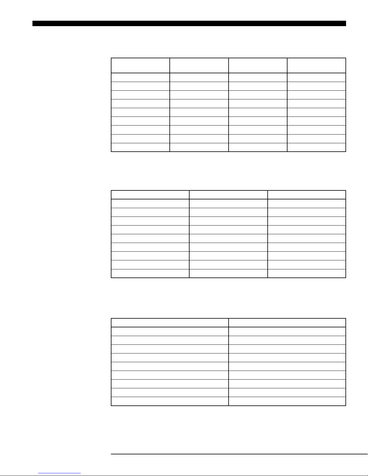
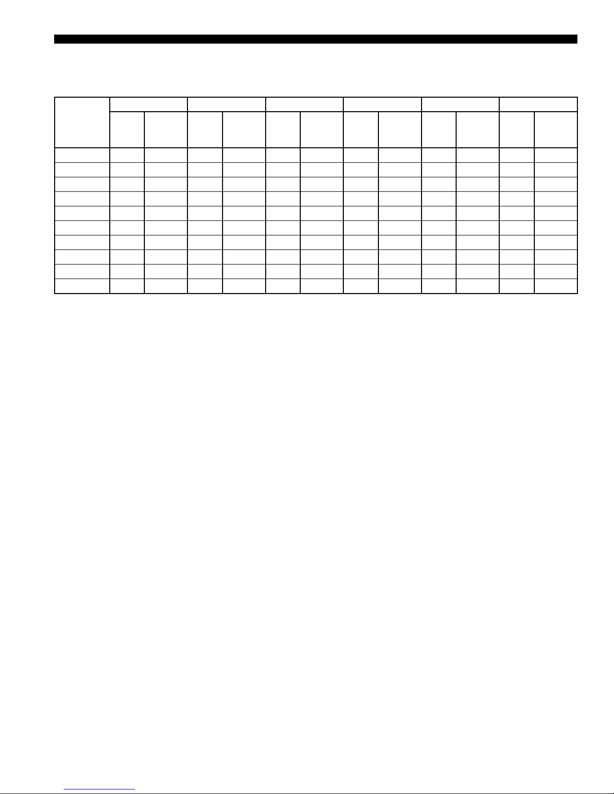
TABLE 1 - DX COOLING CORRECTION FACTORS
AIR FLOW PERCENT TOTAL CAPACITY
80 0.967 0.900 0.980
85 0.976 0.926 0.985
90 0.984 0.951 0.990
95 0.991 0.976 0.995
100 1.000 1.000 1.000
105 1.006 1.024 1.003
110 1.013 1.047 1.007
115 1.019 1.070 1.012
120 1.025 1.093 1.016
SENSIBLE
CAPACITY
COMPRESSOR
TABLE 2 - WATERSIDE ECONOMIZER CORRECTION FACTORS
AIR FLOW PERCENT TOTAL CAPACITY SENSIBLE CAPACITY
80 0.883 0.863
85 0.914 0.899
90 0.944 0.934
95 0.973 0.968
100 1.000 1.000
105 1.026 1.031
110 1.052 1.061
115 1.076 1.090
120 1.100 1.118
POWER
TABLE 3 - HOT WATER HEATING CORRECTION FACTORS
JOHNSON CONTROLS
AIR FLOW PERCENT TOTAL CAPACITY
80 0.903
85 0.929
90 0.953
95 0.977
100 1.000
105 1.020
110 1.042
115 1.061
120 1.082
17
Page 18

FORM 145.05-EG2 (618)
Operating Limitations
TABLE 4 - OPERATING LIMITATIONS — LSWU025-LSWU105
MINIMUM MAXIMUM
Entering Air DX Coil-Dry Bulb 75.0°F 85.0°F
Entering Air DX Coil-Wet Bulb 62.0°F 72.0°F
Condenser Water Flow 2.5 GPM/Ton 3.0 GPM/Ton
Entering Cond. Water Temp with Economizer 40.0°F 90.0°F
Entering Cond. Water Temp with Condenser
Water Control Valve
Entering Cond. Water Temp w/o Condenser
Water Control Valve
Steam Heat-Steam Pressure 5 psig 15 psig
Hot Water Heat Entering Water Temp 140.0°F 160.0°F
40.0°F 90.0°F
60.0°F 90.0°F
18
JOHNSON CONTROLS
Page 19
FORM 145.05-EG2 (618)
Physical Data
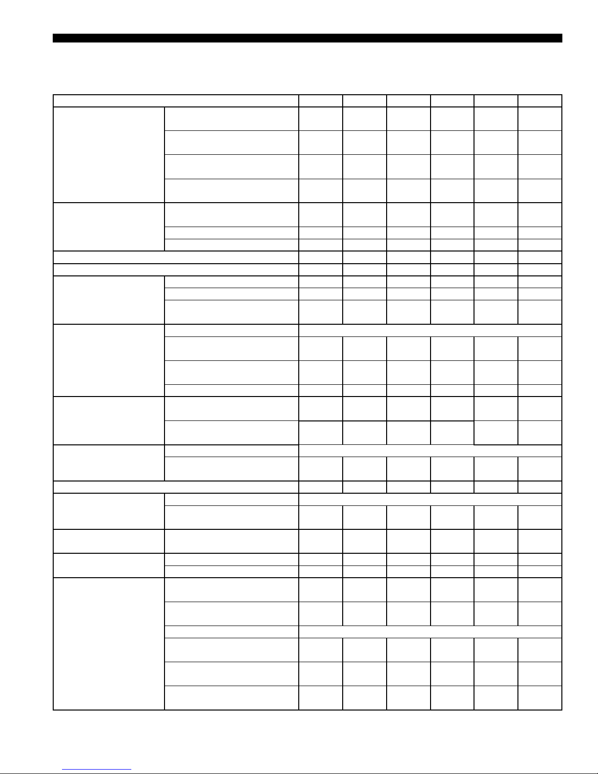
TABLE 5 - LSWU025-LSWU060
Model Nominal Tons 025 032 035 040 050 060
Maximum Design Air Flow Standard - CFM
Maximum Design Air Flow- High
Air Flow Range
Cabinet Dimensions
EER 14.3 13.6 13.3 13.1 14.2 13.3
EER - High Efciency 15.3 14.2 14.2 13.6 14.9 13.8
Cooling Coil 3/8" OD
Supply Fan
Filters
Compressors
Number of Capacity Steps 6 6 6 6 9 9
Condensers
Condenser Water
Connections
Waterside Economizer
Coil 1/2" OD
Heating
Efciency - CFM
Minimum Design Air Flow Standard - CFM
Minimum Design Air Flow - High
Efciency CFM
Depth (Excluding Filter Section)
- Inches
Length - Inches 78 78 78 78 100 100
Height - Inches 79.5 79.5 79.5 79.5 90 90
Face Area - Square Feet 17.8 22.2 26.7 26.7 40.1 40.1
Rows 4 4 4 6 5 6
Fins Per Inch (Standard/High
Efciency)
Fan Type Airfoil Plenum Fan (SWSI)
Diameter - Inches/Class Standard
Diameter - Inches/Class - High
Capacity Fan
Fan Motor HP 5 - 20 10 - 25 10 - 25 10 - 25 15 - 40 15 - 40
4 Inch Deep - MERV 8
20X20X4 / 24X20X4 / 24X24X4
4 Inch Deep - MERV 13
20X20X4 / 24X20X4 / 24X24X4
Type Scroll / *Scroll with Capacity Modulation
Compressor Quantity / Nominal
HP
Type Shell and Tube
Quantity (2 refrigerant circuits
per condenser)
Water In and Out Copper
Victaulic Connections - Inches
Face Area - Square Feet 17.8 22.2 26.7 26.7 40.1 40.1
Rows/Fins Per Inch 4/11 4/11 4/11 4/11 4/11 4/11
Hot Water Coil Face Area Square Feet
Hot Water Coil Rows/Fins Per
Inch
Steam Coil Consult Factory
Electric Heat - KW - 240/3/60
Nominal
Electric Heat - KW - 480/3/60
Nominal
Electric Heat - KW - 600/3/60
Nominal
10,500 13,300 15,500 16,000 20,000 24,000
8,600 11,000 13,200 13,200 20,000 20,000
7,200 9,000 10,800 10,800 16,000 16,000
6,300 7,800 9,400 9,400 14,100 14,100
70 70 70 70 76 76
12/17 12/17 12/17 12/17 12/17 12/17
25/Class II25/Class II28/Class II28/Class II32/Class II36/Class
None None None None
3 / 6 / 0 3 / 6 / 0 3 / 6 / 0 3 / 6 / 0 0 / 6 / 6 0 / 6 / 6
3 / 6 / 0 3 / 6 / 0 3 / 6 / 0 3 / 6 / 0 0 / 6 / 6 0 / 6 / 6
10* + 10 15* + 11 15* + 13 15* + 15 15*+2-11 15*+2-15
1 1 1 1 2 2
2.625 2.625 2.625 2.625 2.625 2.625
8.8 12.0 15.2 15.2 23.3 23.3
1/12 1/12 1/12 1/12 1/12 1/12
17.5 17.5/35.0 17.5/35.0 17.5/35.0 35.0/52.5 35.0/52.5
17.5 17.5/35.0 17.5/35.0 17.5/35.0 35.0/52.5 35.0/52.5
17.5 17.5/35.0 17.5/35.0 17.5/35.0 35.0/52.5 35.0/52.5
II
JOHNSON CONTROLS
19
Page 20
FORM 145.05-EG2 (618)
Physical Data (Cont’d)
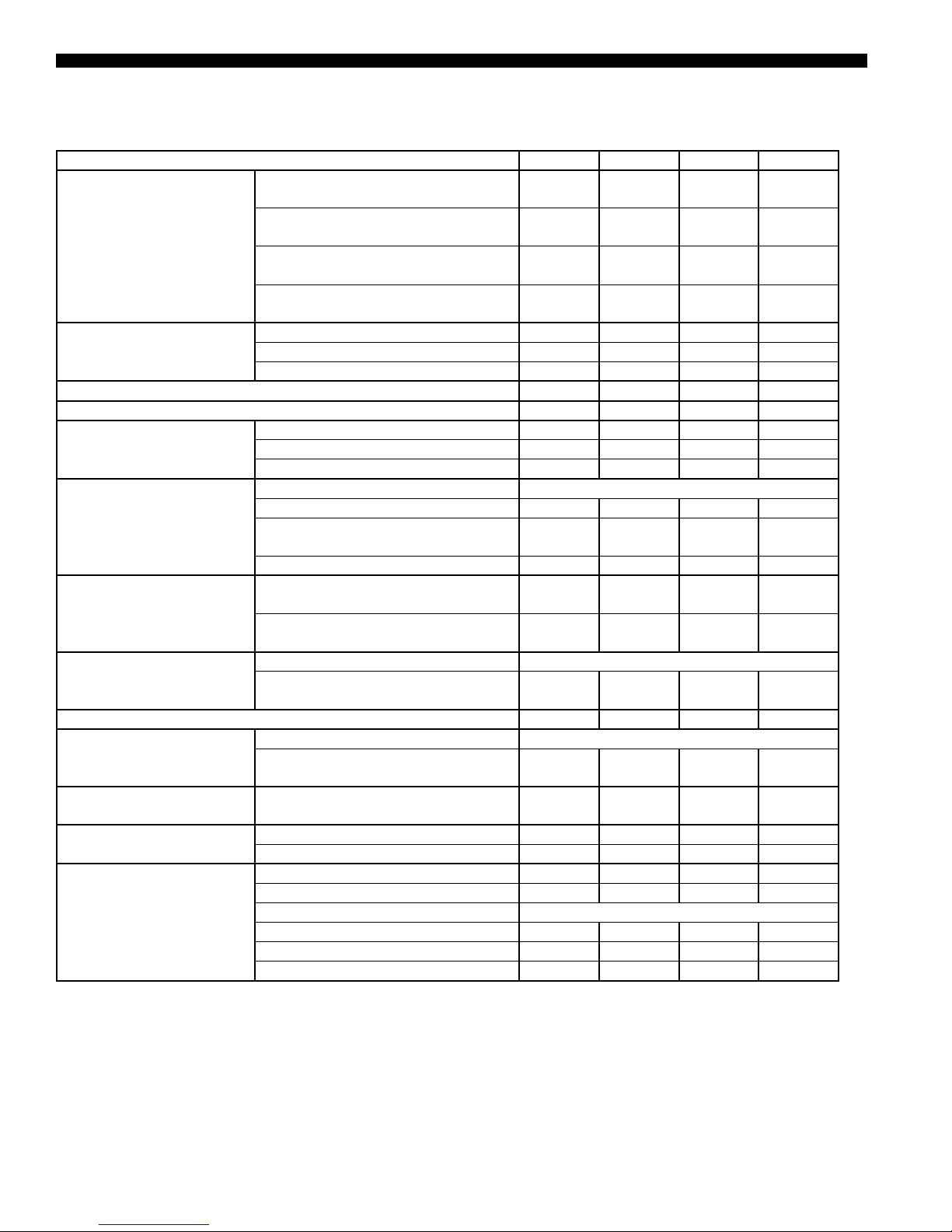
TABLE 6 - LSWU070-LSWU105
Nominal Capacity, Tons 70 80 95 105
Maximum Design Air Flow - Standard CFM
Maximum Design Air Flow- High
Air Flow Range
Cabinet Dimensions
EER 14.1 13.7 13.7 13.3
EER - High Efciency 14.5 14.1 14.1 13.7
Cooling Coil
Supply Fan
Filters
Compressors
Number of Capacity Steps 4 4 6 6
Condensers
Condenser Water
Connections
Waterside Economizer Coil
Heating
Efciency - CFM
Minimum Design Air Flow - Standard CFM
Minimum Design Air Flow - High
Efciency - CFM
Depth (Excluding Filter Section) - Inches 96 96 96 96
Length - Inches 130 130 130 130
Height - Inches 102 102 102 102
Face Area - Square Feet 49.7 56.5 60.3 60.3
Rows 4 5 5 6
Fins Per Inch (Standard/High Efciency) 12/17 12/17 12/17 12/17
Fan Type Airfoil Plenum Fan (SWSI)
Diameter - Inches/Class - Standard 36/Class II 36/Class II 40/Class II 40/Class II
Diameter - Inches/Class - High Capacity
Fan
Fan Motor HP 15 - 40 15 - 40 20 - 50 20 - 50
4 Inch Deep - MERV 8 20X20X4 /
24X20X4
4 Inch Deep - MERV 13 20X20X4 /
24X20X4
Type Scroll
Compressor Quantity / Nominal HP
Type Shell and Tube
Quantity (2 refrigerant circuits per
condenser)
Water In and Out Copper Victaulic
Connections - Inches
Face Area - Square Feet 49.7 56.5 60.3 60.3
Rows/Fins Per Inch 4/11 4/11 4/11 4/11
Hot Water Coil Face Area - Square Feet 35.8 40.6 43.3 43.3
Hot Water Coil Rows/Fins Per Inch 1/12 1/12 1/12 1/12
Steam Coil Consult Factory
Electric Heat - KW - 240/3/60 Nominal 17.5/35.0 17.5/35.0 35.0/52.5 35.0/52.5
Electric Heat - KW - 480/3/60 Nominal 17.5/35.0 17.5/35.0 35.0/52.5 35.0/52.5
Electric Heat - KW - 600/3/60 Nominal 17.5/35.0 17.5/35.0 35.0/52.5 35.0/52.5
29,800 33,900 36,100 36,100
24,800 28,200 30,100 30,100
19,900 22,600 24,200 24,200
17,400 19,800 21,200 21,200
40/Class II 40/Class II None None
8 / 12 8 / 12 8 / 12 8 / 12
8 / 12 8 / 12 8 / 12 8 / 12
2 - 15 +
2 - 13
2 2 3 3
3.125 3.125 3.125 3.125
4 - 15 6 - 13 6 - 15
20
JOHNSON CONTROLS
Page 21
FORM 145.05-EG2 (618)
TABLE 7 - REFRIGERANT CHARGE DATA – LSWU060-LSWU105
COMP A COMP B COMP C COMP D COMP E COMP F
MODEL #
LSWU025 10 20.0 10 20.0 - - - - - - - -
LSWU032 15 21.5 11 21.5 - - - - - - - -
LSWU035 15 23.0 13 23.0 - - - - - - - -
LSWU040 15 27.0 15 27.0 - - - - - - - -
LSWU050 15 28.5 11 25.0 11 25.0 - - - - - -
LSWU060 15 26.5 15 26.5 15 27.5 - - - - - -
LSWU070 15 22.5 15 22.5 15 22.50 15 22.5 - - - -
LSWU080 15 23.25 15 23.25 15 25.3 15 25.3 - - - -
LSWU095 13 19.0 13 19.0 13 23.50 13 23.5 13 23.5 13 23.5
LSWU105 15 19.0 15 19.0 15 23.50 15 23.5 15 27.5 15 27.5
NORM
HP
410A
CHARGE-
LBS
NORM
HP
410A
CHARGE-
LBS
NORM
HP
410A
CHARGE-
LBS
NORM
HP
410A
CHARGE-
LBS
NORM
HP
410A
CHARGE-
LBS
NORM
HP
CHARGE-
410A
LBS
JOHNSON CONTROLS
21
Page 22
FORM 145.05-EG2 (618)
Cooling Performance Data
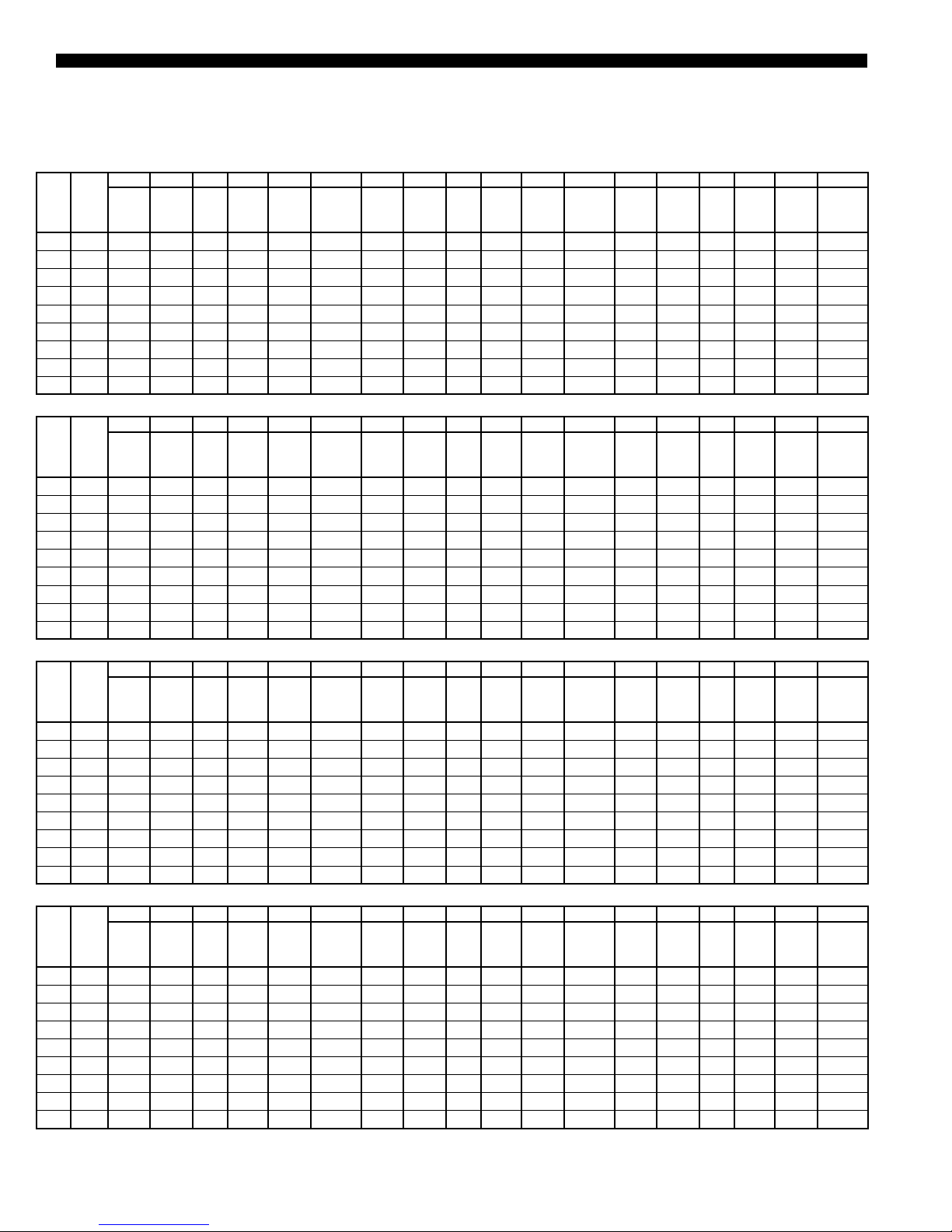
TABLE 8 - LSWU025
AIR FLOW 10,000 CFM
EWT 80 LWT 90 EWT 80 LWT 92 EWT 85 LWT 95
EDB EWB
TMBH SMBH LDB LWB
75 62 292 249 52.4 51.7 14.6 68.3 290 248 52.5 51.8 15.0 56.8 287 246 52.6 51.9 15.6 67.9
75 67 3 11 195 57.6 57.2 14.7 72.2 308 194 57.6 57.3 15.0 59.9 304 193 57.8 57.5 15.6 71.5
75 72 336 141 62.8 62.6 14.7 77.3 334 140 62.9 62.7 15.0 64.2 330 139 63.0 62.9 15.6 76.6
80 62 301 296 53.0 51.3 14.6 70.3 299 294 53.1 51.4 15.0 58.3 296 292 53.3 51.5 15.6 69.7
80 67 312 248 57.7 57.2 14.7 72.4 310 247 57.7 57.2 15.0 60.2 306 245 57.9 57.4 15.6 71.8
80 72 337 194 62.9 62.6 14.7 77.4 334 193 63.0 62.6 15.0 64.3 330 191 63.1 62.8 15.6 76.7
85 62 319 319 55.9 50.6 14.6 73.7 317 317 56.0 50.7 15.0 61.3 313 313 56.4 50.8 15.6 73.3
85 67 323 297 58.1 56.7 14.7 74.7 321 296 58.2 56.8 15.0 62.1 317 294 58.4 56.9 15.6 74.1
85 72 337 246 63.0 62.5 14.7 77.4 335 246 63.0 62.6 15.0 64.3 330 244 63.2 62.7 15.6 76.7
EWT 85 LWT 97 EWT 90 LWT 100 EWT 90 LWT 102
EDB EWB
TMBH SMBH LDB LWB
75 62 284 245 52.8 52.0 15.9 56.4 280.9 243.3 52.9 52.1 16.5 67.4 278.4 242 53.0 52.2 16.9 56.0
75 67 302 192 57.8 57.5 16.0 59.5 297.9 190.4 58.0 57.7 16.5 70.9 295.7 189.5 58.1 57.8 16.9 58.9
75 72 327 138 63.2 63.1 16.0 63.6 323 136 63.3 63.2 16.6 75.9 320 135 63.4 63.3 17.0 63.0
80 62 293 291 53.5 51.6 15.9 57.9 289.9 288.3 53.7 51.7 16.5 69.3 287.4 286.4 53.9 51.8 16.9 57.5
80 67 304 245 57.9 57.4 16.0 59.8 300.6 243 58.1 57.5 16.6 71.4 299 242.3 58.1 57.6 16.9 59.5
80 72 328 190 63.2 62.9 16.0 63.7 323 188.8 63.3 63.0 16.6 75.9 320.4 187.8 63.4 63.1 17.0 63.1
85 62 3 11 311 56.6 50.9 16.0 60.9 307.5 307.5 56.9 51.0 16.6 72.8 305.4 305.4 57.1 51.1 16.9 60.5
85 67 315 293 58.4 57.0 16.0 61.6 311 290.5 58.6 57.1 16.6 73.5 309 289.5 58.7 57.2 16.9 61.1
85 72 328 243 63.3 62.8 16.0 63.7 323.8 241.4 63.4 62.9 16.6 76.1 320.8 240.3 63.5 63.0 17.0 63.1
EWT 80 LWT 90 EWT 80 LWT 92 EWT 85 LWT 95
EDB EWB
TMBH SMBH LDB LWB
75 62 297 235 48.5 48.4 14.6 69.4 295 234 48.6 48.5 15.0 57.6 291 232 48.8 48.7 15.6 68.9
75 67 318 188 54.2 54.1 14.7 73.6 316 187 54.3 54.2 15.0 61.2 312 185 54.5 54.4 15.6 72.9
75 72 345 142 59.7 59.6 14.7 79.1 343 141 59.8 59.7 15.0 65.7 338 139 60.0 59.9 15.6 78.3
80 62 306 281 48.1 48.0 14.6 71.2 304 280 48.2 48.1 15.0 59.2 300 278 48.4 48.3 15.6 70.7
80 67 319 233 53.9 53.8 14.7 73.9 317 232 54.0 53.9 15.0 61.3 313 231 54.1 54.0 15.6 73.3
80 72 346 187 59.5 59.4 14.6 79.2 343 186 59.6 59.5 15.0 65.7 338 184 59.8 59.7 15.6 78.4
85 62 319 319 48.5 47.2 14.6 73.9 317 317 48.7 47.4 15.0 61.4 314 314 49.1 47.5 15.6 73.4
85 67 330 280 53.4 53.3 14.6 76.0 327 279 53.5 53.4 15.0 63.1 324 277 53.7 53.6 15.6 75.4
85 72 346 232 59.3 59.2 14.7 79.2 343 231 59.4 59.3 15.0 65.8 339 229 59.6 59.5 15.6 78.4
EWT 85 LWT 97 EWT 90 LWT 100 EWT 90 LWT 102
EDB EWB
TMBH SMBH LDB LWB
75 62 289 231 48.9 48.8 15.9 57.2 285 229 49.2 49.1 16.5 68.3 283 228 49.3 49.2 16.9 56.7
75 67 309 184 54.6 54.5 16.0 60.6 305 182 54.8 54.7 16.6 72.2 302 181 54.9 54.8 16.9 60.0
75 72 336 138 60.1 60.0 16.0 65.0 331 137 60.3 60.2 16.6 77.5 328 136 60.4 60.3 17.0 64.4
80 62 298 277 48.5 48.4 15.9 58.8 294 275 48.7 48.6 16.5 70.1 292 274 48.8 48.7 16.9 58.3
80 67 3 11 230 54.2 54.1 16.0 60.9 307 228 54.4 54.3 16.6 72.7 304 227 54.6 54.5 17.0 60.4
80 72 336 183 59.9 59.8 16.0 65.1 331 181 60.1 60.0 16.6 77.6 328 180 60.2 60.1 17.0 64.4
85 62 312 312 49.3 47.6 16.0 61.1 309 309 49.7 47.8 16.6 73.0 306 306 50.0 48.0 16.9 60.7
85 67 321 276 53.8 53.7 16.0 62.6 317 274 54.1 54.0 16.6 74.7 314 273 54.2 54.1 17.0 62.0
85 72 336 228 59.7 59.6 16.0 65.1 332 226 59.9 59.8 16.6 77.7 329 225 60.0 59.9 17.0 64.4
WATER
COMP
KW
FLOW
TMBH SMBH LDB LWB
GPM
AIR FLOW 10,000 CFM
WATER
COMP
KW
FLOW
TMBH SMBH LDB LWB
GPM
HIGH EFFICIENCY - AIR FLOW 8,000 CFM
WATER
COMP
KW
FLOW
TMBH SMBH LDB LWB
GPM
HIGH EFFICIENCY - AIR FLOW 8,000 CFM
WATER
COMP
KW
FLOW
TMBH SMBH LDB LWB
GPM
COMP
KW
COMP
KW
COMP
KW
COMP
KW
WATER
FLOW
GPM
WATER
FLOW
GPM
WATER
FLOW
GPM
WATER
FLOW
GPM
TMBH SMBH LDB LWB
TMBH SMBH LDB LWB
TMBH SMBH LDB LWB
TMBH SMBH LDB LWB
COMP
KW
COMP
KW
COMP
KW
COMP
KW
WATER
WATER
WATER
WATER
FLOW
GPM
FLOW
GPM
FLOW
GPM
FLOW
GPM
NOTE: EDB-entering dry bulb temp, EWB-entering wet bulb temp, EWT-entering water temp, LWT-leaving water temp, LDB-leaving dry bulb temp,
LWB-leaving wet bulb temp, TMBH-total capacity, SMBH-sensible capacity
22
JOHNSON CONTROLS
Page 23
FORM 145.05-EG2 (618)
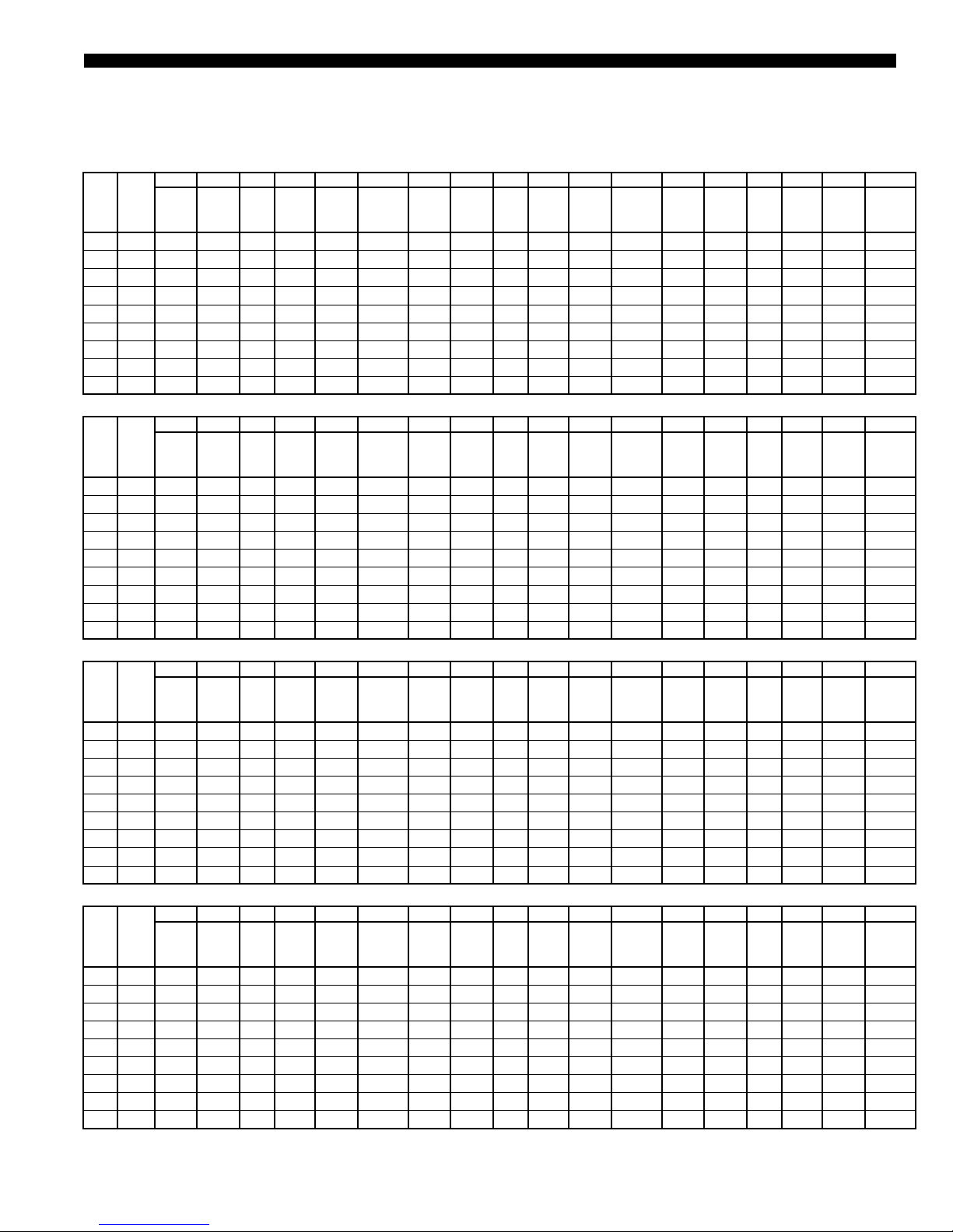
TABLE 9 - LSWU032
AIR FLOW 12,800 CFM
EWT 80 LWT 90 EWT 80 LWT 92 EWT 85 LWT 95
EDB EWB
TMBH SMBH LDB LWB
75 62 371 320 52.3 51.8 19.8 87.7 369 319 52.4 51.9 20.2 72.9 364 316 52.6 52.0 20.9 87.1
75 67 399 251 57.5 57.2 20.1 93.5 395 249 57.6 57.3 20.5 77.5 390 247 57.8 57.5 21.2 92.5
75 72 431 181 62.7 62.6 20.6 100.2 427 179 62.9 62.7 21.0 83.1 422 177 63.0 62.9 21.6 99.1
80 62 385 380 52.9 51.3 20.0 90.7 382 378 53.0 51.4 20.4 75.3 378 375 53.3 51.5 21.1 89.9
80 67 399 318 57.6 57.2 20.1 93.6 396 316 57.7 57.2 20.6 77.7 392 315 57.8 57.3 21.2 92.8
80 72 431 248 62.9 62.6 20.6 100.3 428 247 63.0 62.6 21.0 83.2 423 245 63.1 62.8 21.6 99.3
85 62 407 407 55.9 50.6 20.4 95.3 404 404 56.1 50.7 20.8 79.2 400 400 56.4 50.8 21.4 94.7
85 67 413 382 57.9 56.7 20.4 96.5 410 381 58.0 56.8 20.8 80.1 405 378 58.2 56.9 21.4 95.7
85 72 432 316 62.9 62.5 20.6 100.5 429 315 63.0 62.6 21.0 83.4 423 313 63.1 62.7 21.7 99.5
EWT 85 LWT 97 EWT 90 LWT 100 EWT 90 LWT 102
EDB EWB
TMBH SMBH LDB LWB
75 62 362 315 52.7 52.1 21.3 72.4 357 313 52.8 52.2 22.0 86.4 355 311 52.9 52.3 22.5 71.9
75 67 387 246 57.8 57.5 21.6 76.8 382 244 58.0 57.7 22.3 91.5 378 243 58.0 57.8 22.7 76.0
75 72 418 176 63.1 62.9 22.0 82.3 412 174 63.2 63.1 22.7 97.9 409 173 63.3 63.2 23.2 81.3
80 62 375 374 53.3 51.6 21.5 74.8 370 370 53.6 51.8 22.2 89.2 368 368 53.8 51.8 22.7 74.2
80 67 388 313 57.9 57.5 21.6 77.0 383 3 11 58.1 57.6 22.3 91.9 379 310 58.1 57.7 22.8 76.2
80 72 419 244 63.2 62.9 22.1 82.4 414 242 63.3 63.0 22.7 98.3 410 241 63.4 63.1 23.2 81.5
85 62 398 398 56.6 50.9 21.9 78.7 393 393 56.9 51.0 22.6 94.0 391 391 57.1 51.1 23.0 78.2
85 67 402 377 58.3 57.0 21.9 79.5 397 374 58.5 57.2 22.6 94.9 394 373 58.5 57.2 23.1 78.7
85 72 420 3 11 63.3 62.8 22.1 82.6 415 309 63.4 62.9 22.7 98.4 411 308 63.5 63.0 23.2 81.7
EWT 80 LWT 90 EWT 80 LWT 92 EWT 85 LWT 95
EDB EWB
TMBH SMBH LDB LWB
75 62 377 298 48.1 48.0 19.9 89.0 374 296 48.3 48.2 20.3 73.9 370 294 48.5 48.4 20.9 88.2
75 67 407 239 53.8 53.7 20.3 95.2 404 237 54.0 53.9 20.7 79.0 398 235 54.2 54.1 21.3 94.3
75 72 440 181 59.4 59.3 20.8 102.3 437 180 59.5 59.4 21.2 84.9 431 178 59.7 59.6 21.8 101.2
80 62 390 356 47.7 47.6 20.1 91.6 387 355 47.8 47.7 20.5 76.1 382 353 47.9 47.8 21.2 90.9
80 67 408 296 53.5 53.4 20.3 95.4 405 294 53.7 53.6 20.7 79.3 399 292 53.8 53.7 21.3 94.4
80 72 442 237 59.2 59.1 20.8 102.6 438 236 59.3 59.2 21.2 85.0 432 234 59.5 59.4 21.8 101.4
85 62 406 406 47.9 47.0 20.4 95.2 404 404 48.0 47.0 20.8 79.1 400 400 48.4 47.2 21.5 94.6
85 67 419 355 53.0 52.9 20.5 97.7 416 353 53.1 53.0 21.0 81.2 411 351 53.3 53.2 21.6 96.9
85 72 442 294 58.9 58.8 20.8 102.7 439 292 59.1 59.0 21.2 85.2 433 290 59.2 59.1 21.8 101.5
EWT 85 LWT 97 EWT 90 LWT 100 EWT 90 LWT 102
EDB EWB
TMBH SMBH LDB LWB
75 62 367 293 48.5 48.4 21.4 73.3 362 290 48.8 48.7 22.1 87.4 359 289 48.9 48.8 22.5 72.6
75 67 395 234 54.2 54.1 21.7 78.1 390 232 54.4 54.3 22.4 93.2 386 230 54.6 54.5 22.9 77.4
75 72 428 176 59.7 59.7 22.2 84.0 422 174 60.0 59.9 22.9 100.1 418 173 60.1 60.0 23.4 83.0
80 62 380 351 48.1 48.0 21.6 75.6 375 349 48.3 48.2 22.3 90.1 372 347 48.5 48.4 22.8 74.9
80 67 396 291 53.9 53.8 21.8 78.4 391 289 54.1 54.0 22.5 93.6 388 287 54.3 54.2 23.0 77.7
80 72 429 233 59.5 59.4 22.2 84.2 423 230 59.8 59.7 22.9 100.3 419 229 59.9 59.8 23.4 83.2
85 62 396 396 48.8 47.4 21.9 78.5 392 392 49.1 47.6 22.6 93.9 389 389 49.4 47.7 23.1 78.0
85 67 408 350 53.4 53.3 22.0 80.5 403 347 53.7 53.6 22.7 96.0 400 346 53.8 53.7 23.2 79.8
85 72 430 289 59.3 59.2 22.3 84.2 423 287 59.5 59.4 22.9 100.3 420 285 59.7 59.6 23.4 83.3
WATER
COMP
KW
FLOW
GPM
TMBH SMBH LDB LWB
AIR FLOW 12,800 CFM
WATER
COMP
KW
FLOW
GPM
TMBH SMBH LDB LWB
HIGH EFFICIENCY - AIR FLOW 10,000 CFM
WATER
COMP
KW
FLOW
GPM
TMBH SMBH LDB LWB
HIGH EFFICIENCY - AIR FLOW 10,000 CFM
WATER
COMP
KW
FLOW
GPM
TMBH SMBH LDB LWB
COMP
KW
COMP
KW
COMP
KW
COMP
KW
WATER
FLOW
GPM
WATER
FLOW
GPM
WATER
FLOW
GPM
WATER
FLOW
GPM
TMBH SMBH LDB LWB
TMBH SMBH LDB LWB
TMBH SMBH LDB LWB
TMBH SMBH LDB LWB
COMP
KW
COMP
KW
COMP
KW
COMP
KW
WATER
FLOW
WATER
FLOW
WATER
FLOW
WATER
FLOW
GPM
GPM
GPM
GPM
NOTE: EDB-entering dry bulb temp, EWB-entering wet bulb temp, EWT-entering water temp, LWT-leaving water temp, LDB-leaving dry bulb temp,
LWB-leaving wet bulb temp, TMBH-total capacity, SMBH-sensible capacity
JOHNSON CONTROLS
23
Page 24
FORM 145.05-EG2 (618)
Cooling Performance Data (Cont’d)
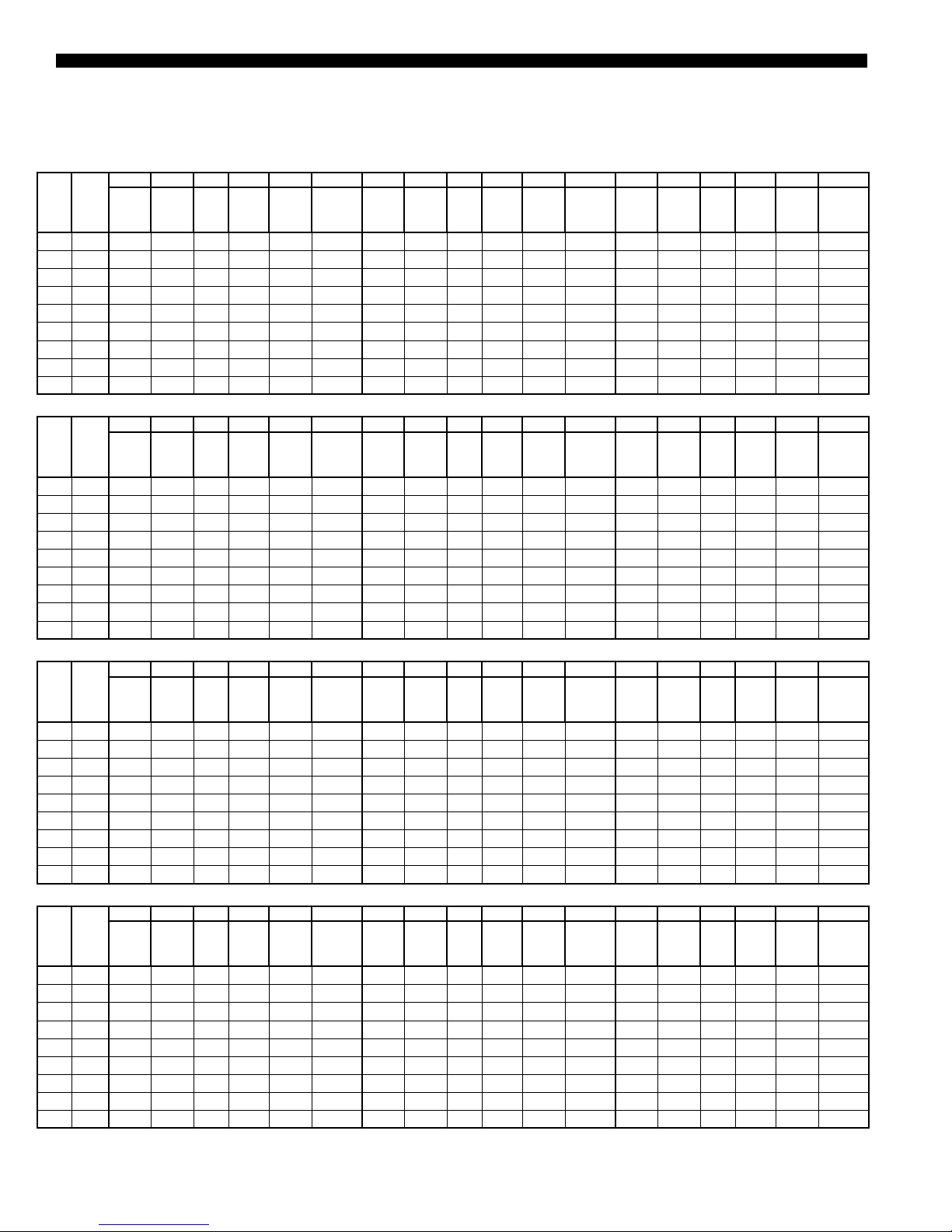
TABLE 10 - LSWU035
AIR FLOW 14,000 CFM
EWT 80 LWT 90 EWT 80 LWT 92 EWT 85 LWT 95
EDB EWB
TMBH SMBH LDB LWB
75 62 402 348 52.4 51.9 21.4 95.0 399 346 52.6 52.0 21.8 78.9 394 344 52.7 52.1 22.5 94.1
75 67 428 272 57.7 57.4 21.7 100.4 424 271 57.7 57.5 22.2 83.3 419 269 57.8 57.6 22.8 99.4
75 72 462 195 62.9 62.8 22.3 107.7 459 194 63.0 62.9 22.7 89.4 453 192 63.1 63.0 23.4 106.5
80 62 415 413 53.1 51.5 21.6 97.8 413 4 11 53.2 51.5 22.1 81.4 408 407 53.5 51.7 22.7 97.2
80 67 429 346 57.7 57.3 21.8 100.8 427 345 57.8 57.4 22.2 83.7 421 343 57.9 57.5 22.9 99.9
80 72 463 270 63.0 62.8 22.3 107.9 459 268 63.1 62.8 22.7 89.5 454 266 63.2 63.0 23.3 106.7
85 62 440 440 56.2 50.8 22.1 103.1 438 438 56.4 50.8 22.5 85.7 433 433 56.7 51.0 23.1 102.4
85 67 445 416 58.0 56.9 22.1 104.2 442 415 58.1 57.0 22.5 86.6 437 412 58.3 57.1 23.2 103.3
85 72 464 344 63.0 62.7 22.3 108.0 460 343 63.1 62.8 22.7 89.7 454 341 63.2 62.9 23.4 106.8
EWT 85 LWT 97 EWT 90 LWT 100 EWT 90 LWT 102
EDB EWB
TMBH SMBH LDB LWB
75 62 391 342 52.8 52.2 22.9 78.2 386 340 52.9 52.3 23.7 93.4 383 338 53.1 52.4 24.2 77.6
75 67 415 267 58.0 57.7 23.3 82.4 410 265 58.1 57.9 24.0 98.3 406 264 58.2 58.0 24.5 81.6
75 72 449 190 63.2 63.1 23.8 88.4 443 188 63.4 63.3 24.5 105.3 439 187 63.4 63.3 25.0 87.4
80 62 405 405 53.6 51.8 23.2 80.8 401 401 53.9 51.9 23.9 96.6 398 398 54.0 52.0 24.4 80.3
80 67 419 342 58.0 57.6 23.3 83.1 414 339 58.2 57.7 24.1 99.1 411 338 58.2 57.8 24.6 82.4
80 72 450 265 63.3 63.0 23.8 88.5 444 263 63.4 63.2 24.5 105.5 440 261 63.5 63.3 25.0 87.5
85 62 430 430 56.9 51.0 23.6 85.1 425 425 57.2 51.2 24.3 101.6 422 422 57.4 51.3 24.8 84.4
85 67 434 410 58.4 57.2 23.6 85.7 429 408 58.5 57.3 24.3 102.3 425 406 58.7 57.4 24.8 85.0
85 72 451 339 63.3 63.0 23.8 88.7 445 337 63.5 63.1 24.5 105.7 441 336 63.5 63.2 25.0 87.7
EWT 80 LWT 90 EWT 80 LWT 92 EWT 85 LWT 95
EDB EWB
TMBH SMBH LDB LWB
75 62 406 323 48.5 48.4 21.4 95.8 402 321 48.7 48.6 21.9 79.5 398 319 48.8 48.7 22.5 94.9
75 67 435 258 54.2 54.1 21.9 101.9 431 256 54.4 54.3 22.3 84.6 425 254 54.5 54.4 23.0 100.8
75 72 472 194 59.7 59.7 22.5 109.7 468 193 59.9 59.8 22.9 91.0 462 191 60.0 59.9 23.5 108.4
80 62 419 387 48.0 47.9 21.7 98.5 416 386 48.1 48.0 22.1 81.8 411 383 48.4 48.3 22.8 97.7
80 67 437 321 53.8 53.7 21.9 102.4 433 319 54.0 53.9 22.3 84.9 428 317 54.2 54.1 23.0 101.3
80 72 472 256 59.6 59.5 22.5 109.8 468 255 59.6 59.5 22.9 91.1 462 252 59.9 59.8 23.5 108.5
85 62 438 438 48.6 47.3 22.1 102.6 435 435 48.8 47.4 22.5 85.2 430 430 49.2 47.6 23.1 101.9
85 67 450 385 53.4 53.3 22.2 105.2 447 384 53.5 53.4 22.6 87.4 441 381 53.7 53.6 23.3 104.1
85 72 473 318 59.3 59.2 22.5 109.9 469 317 59.4 59.3 22.9 91.2 463 315 59.5 59.4 23.5 108.6
EWT 85 LWT 97 EWT 90 LWT 100 EWT 90 LWT 102
EDB EWB
TMBH SMBH LDB LWB
75 62 394 317 49.0 48.9 23.0 78.8 390 315 49.1 49.0 23.7 94.1 386 313 49.3 49.2 24.2 78.1
75 67 422 252 54.7 54.6 23.4 83.7 417 250 54.8 54.7 24.1 99.8 412 248 55.0 54.9 24.6 82.7
75 72 458 189 60.2 60.1 24.0 89.9 452 187 60.4 60.3 24.7 107.1 448 185 60.4 60.4 25.1 88.9
80 62 407 382 48.4 48.3 23.3 81.1 402 379 48.7 48.6 24.0 96.8 399 377 48.9 48.8 24.5 80.4
80 67 425 315 54.3 54.2 23.5 84.1 419 313 54.5 54.4 24.2 100.3 416 312 54.6 54.5 24.7 83.3
80 72 459 251 60.0 59.9 24.0 90.1 453 249 60.1 60.0 24.7 107.4 448 247 60.3 60.2 25.2 89.0
85 62 427 427 49.5 47.7 23.6 84.6 422 422 49.9 47.9 24.3 101.1 419 419 50.2 48.0 24.8 84.0
85 67 438 380 53.8 53.7 23.7 86.6 433 377 54.0 53.9 24.4 103.3 430 376 54.1 54.0 24.9 85.8
85 72 459 313 59.7 59.6 24.0 90.2 453 3 11 59.9 59.8 24.7 107.4 449 310 59.9 59.8 25.2 89.2
WATER
COMP
KW
FLOW
TMBH SMBH LDB LWB
GPM
AIR FLOW 14,000 CFM
WATER
COMP
KW
FLOW
TMBH SMBH LDB LWB
GPM
HIGH EFFICIENCY - AIR FLOW 11,000 CFM
WATER
COMP
KW
FLOW
TMBH SMBH LDB LWB
GPM
HIGH EFFICIENCY - AIR FLOW 11,000 CFM
WATER
COMP
KW
FLOW
TMBH SMBH LDB LWB
GPM
COMP
KW
COMP
KW
COMP
KW
COMP
KW
WATER
FLOW
GPM
WATER
FLOW
GPM
WATER
FLOW
GPM
WATER
FLOW
GPM
TMBH SMBH LDB LWB
TMBH SMBH LDB LWB
TMBH SMBH LDB LWB
TMBH SMBH LDB LWB
COMP
KW
COMP
KW
COMP
KW
COMP
KW
WATER
FLOW
WATER
FLOW
WATER
FLOW
WATER
FLOW
GPM
GPM
GPM
GPM
NOTE: EDB-entering dry bulb temp, EWB-entering wet bulb temp, EWT-entering water temp, LWT-leaving water temp, LDB-leaving dry bulb temp,
LWB-leaving wet bulb temp, TMBH-total capacity, SMBH-sensible capacity
24
JOHNSON CONTROLS
Page 25
FORM 145.05-EG2 (618)
TABLE 11 - LSWU040
AIR FLOW 16,000 CFM
EWT 80 LWT 90 EWT 80 LWT 92 EWT 85 LWT 95
EDB EWB
TMBH SMBH LDB LWB
75 62 454 399 52.4 52.0 23.4 106.7 451 398 52.4 52.1 23.9 88.7 445 395 52.6 52.2 24.6 105.8
75 67 479 3 11 57.7 57.6 23.8 112.0 475 309 57.7 57.7 24.3 93.0 469 307 58.0 57.9 25.0 110.9
75 72 517 221 63.1 63.0 24.7 120.3 513 219 63.1 63.1 25.1 99.8 507 217 63.3 63.2 25.8 119.0
80 62 473 473 53.0 51.5 23.8 110.9 470 470 53.2 51.6 24.3 92.1 465 465 53.5 51.7 25.0 110.0
80 67 488 399 57.5 57.4 24.1 114.1 485 397 57.6 57.4 24.5 94.7 479 394 57.8 57.6 25.2 113.0
80 72 518 308 63.1 63.0 24.7 120.4 514 307 63.1 63.0 25.1 100.0 508 305 63.2 63.1 25.8 119.2
85 62 500 500 56.4 50.8 24.3 116.7 497 497 56.6 50.9 24.8 97.0 492 492 56.9 51.0 25.5 115.8
85 67 503 482 57.6 57.0 24.4 117.3 500 480 57.8 57.1 24.9 97.4 494 477 57.9 57.2 25.6 116.2
85 72 524 398 62.8 62.7 24.8 121.8 520 396 62.9 62.8 25.3 101.1 514 394 63.0 62.9 26.0 120.6
EWT 85 LWT 97 EWT 90 LWT 100 EWT 90 LWT 102
EDB EWB
TMBH SMBH LDB LWB
75 62 442 394 52.6 52.3 25.1 87.9 436 391 52.8 52.5 25.9 104.9 432 389 52.9 52.6 26.4 87.1
75 67 465 306 58.0 57.9 25.5 92.0 459 303 58.1 58.1 26.3 109.7 455 302 58.2 58.1 26.8 91.0
75 72 503 216 63.4 63.3 26.3 98.7 496 213 63.5 63.5 27.0 117.6 491 212 63.6 63.5 27.6 97.6
80 62 462 462 53.6 51.8 25.5 91.4 457 457 53.9 51.9 26.3 109.2 453 453 54.2 52.0 26.8 90.7
80 67 475 393 57.8 57.7 25.7 93.9 469 390 58.0 57.8 26.5 111.9 465 388 58.1 57.9 27.1 92.9
80 72 504 303 63.2 63.2 26.3 98.9 497 301 63.4 63.3 27.1 117.8 492 299 63.6 63.5 27.6 97.7
85 62 489 489 57.0 51.1 26.0 96.3 483 483 57.4 51.2 26.8 115.0 480 480 57.6 51.3 27.4 95.5
85 67 491 475 58.0 57.3 26.1 96.6 484 472 58.2 57.4 26.8 115.2 481 470 58.3 57.5 27.4 95.7
85 72 510 392 63.2 63.1 26.5 100.1 504 390 63.3 63.2 27.2 119.4 500 388 63.3 63.2 27.8 99.1
EWT 80 LWT 90 EWT 80 LWT 92 EWT 85 LWT 95
EDB EWB
TMBH SMBH LDB LWB
75 62 455 370 49.3 49.2 23.4 107.0 452 369 49.4 49.3 23.9 88.9 446 366 49.4 49.3 24.6 106.0
75 67 483 292 55.1 55.0 23.9 113.0 479 291 55.1 55.0 24.4 93.8 474 288 55.1 55.0 25.1 111.9
75 72 523 217 60.6 60.5 24.8 121.6 519 216 60.7 60.6 25.2 100.9 513 214 60.7 60.6 25.9 120.3
80 62 469 447 48.7 48.6 23.7 110.1 467 446 48.8 48.7 24.2 91.5 461 443 48.8 48.7 24.9 109.2
80 67 490 368 54.6 54.5 24.1 114.4 487 367 54.7 54.6 24.6 95.1 480 364 54.7 54.6 25.3 113.3
80 72 524 290 60.4 60.3 24.8 121.7 520 289 60.5 60.4 25.3 101.0 513 287 60.5 60.4 25.9 120.3
85 62 494 494 50.2 48.1 24.2 115.4 491 491 50.4 48.2 24.7 95.8 485 485 50.4 48.2 25.4 114.4
85 67 505 445 54.1 54.0 24.4 117.7 501 443 54.2 54.1 24.9 97.7 495 441 54.2 54.1 25.6 116.5
85 72 527 365 60.0 59.9 24.9 122.4 523 364 60.1 60.0 25.3 101.6 517 361 60.1 60.0 26.0 121.1
EWT 85 LWT 97 EWT 90 LWT 100 EWT 90 LWT 102
EDB EWB
TMBH SMBH LDB LWB
75 62 443 365 49.6 49.5 25.1 88.1 437 362 49.8 49.7 25.9 105.1 434 360 50.0 49.9 26.4 87.3
75 67 470 287 55.4 55.3 25.6 92.8 463 284 55.6 55.5 26.4 110.7 459 283 55.7 55.6 26.9 91.8
75 72 509 212 61.0 60.9 26.4 99.8 501 210 61.1 61.0 27.2 118.8 497 208 61.2 61.1 27.7 98.6
80 62 457 441 49.2 49.1 25.4 90.7 451 438 49.4 49.3 26.2 108.1 448 437 49.4 49.3 26.8 89.9
80 67 477 362 55.0 54.9 25.8 94.1 470 360 55.2 55.1 26.6 112.2 467 358 55.3 55.2 27.1 93.2
80 72 509 285 60.7 60.6 26.4 99.9 503 283 60.9 60.8 27.2 119.1 498 281 61.0 60.9 27.7 98.7
85 62 482 482 51.1 48.4 25.9 95.1 477 477 51.4 48.6 26.7 113.6 473 473 51.7 48.7 27.3 94.4
85 67 492 439 54.5 54.4 26.1 96.8 485 436 54.7 54.6 26.9 115.4 482 435 54.8 54.7 27.4 95.8
85 72 513 360 60.4 60.3 26.5 100.5 506 357 60.6 60.5 27.3 119.9 502 356 60.6 60.5 27.8 99.5
WATER
COMP
KW
FLOW
GPM
TMBH SMBH LDB LWB
AIR FLOW 16,000 CFM
WATER
COMP
KW
FLOW
GPM
TMBH SMBH LDB LWB
HIGH EFFICIENCY - AIR FLOW 13,000 CFM
WATER
COMP
KW
FLOW
GPM
TMBH SMBH LDB LWB
HIGH EFFICIENCY - AIR FLOW 13,000 CFM
WATER
COMP
KW
FLOW
GPM
TMBH SMBH LDB LWB
COMP
KW
COMP
KW
COMP
KW
COMP
KW
WATER
FLOW
GPM
WATER
FLOW
GPM
WATER
FLOW
GPM
WATER
FLOW
GPM
TMBH SMBH LDB LWB
TMBH SMBH LDB LWB
TMBH SMBH LDB LWB
TMBH SMBH LDB LWB
COMP
KW
COMP
KW
COMP
KW
COMP
KW
WATER
FLOW
WATER
FLOW
WATER
FLOW
WATER
FLOW
GPM
GPM
GPM
GPM
NOTE: EDB-entering dry bulb temp, EWB-entering wet bulb temp, EWT-entering water temp, LWT-leaving water temp, LDB-leaving dry bulb temp,
LWB-leaving wet bulb temp, TMBH-total capacity, SMBH-sensible capacity
JOHNSON CONTROLS
25
Page 26

FORM 145.05-EG2 (618)
Cooling Performance Data (Cont’d)
TABLE 12 - LSWU050
AIR FLOW 20,000 CFM
EWT 80 LWT 90 EWT 80 LWT 92 EWT 85 LWT 95
EDB EWB
TMBH SMBH LDB LWB
75 62 572 503 52.2 51.9 28.4 133.7 567 500 52.3 52.0 29.0 111.0 560 497 52.4 52.2 29.9 132.5
75 67 607 392 57.6 57.5 28.8 141.0 601 390 57.7 57.6 29.4 117.0 593 387 57.8 57.7 30.3 139.3
75 72 656 279 62.9 62.9 29.5 151.3 651 277 63.0 63.0 30.0 125.5 642 274 63.1 63.1 30.9 149.4
80 62 596 596 52.8 51.4 28.6 138.7 592 592 53.0 51.5 29.2 115.3 586 586 53.3 51.6 30.1 137.7
80 67 613 503 57.4 57.3 28.9 142.2 608 501 57.5 57.4 29.5 118.1 601 497 57.6 57.5 30.4 140.9
80 72 657 389 62.9 62.8 29.5 151.6 651 387 63.0 62.9 30.1 125.6 642 384 63.1 63.0 31.0 149.6
85 62 632 632 56.1 50.7 29.0 146.1 627 627 56.3 50.8 29.6 121.3 620 620 56.6 50.9 30.5 144.9
85 67 637 604 57.6 56.9 29.1 147.3 632 602 57.7 56.9 29.7 122.2 624 598 57.8 57.1 30.6 145.6
85 72 659 499 62.8 62.7 29.5 151.9 653 497 62.8 62.7 30.1 125.9 644 494 63.0 62.9 31.0 150.0
EWT 85 LWT 97 EWT 90 LWT 100 EWT 90 LWT 102
EDB EWB
TMBH SMBH LDB LWB
75 62 555 494 52.6 52.3 30.5 109.9 548 490 52.7 52.4 31.5 131.2 543 488 52.8 52.5 32.1 108.8
75 67 588 385 57.9 57.8 30.9 115.6 580 381 58.0 58.0 31.9 137.7 574 379 58.2 58.1 32.5 114.2
75 72 636 272 63.3 63.2 31.6 124.0 627 269 63.4 63.3 32.5 147.5 622 267 63.5 63.4 33.1 122.4
80 62 581 581 53.5 51.7 30.7 114.4 574 574 53.8 51.9 31.8 136.5 570 570 54.0 51.9 32.4 113.4
80 67 596 495 57.7 57.6 31.0 117.0 589 492 57.8 57.7 32.0 139.7 584 490 57.9 57.8 32.7 115.9
80 72 638 382 63.2 63.1 31.5 124.2 628 379 63.3 63.2 32.5 147.8 622 377 63.4 63.3 33.1 122.5
85 62 616 616 56.8 51.0 31.1 120.4 608 608 57.2 51.2 32.1 143.5 604 604 57.4 51.2 32.8 119.3
85 67 619 595 58.0 57.2 31.2 120.9 6 11 591 58.2 57.3 32.2 144.3 607 589 58.2 57.4 32.8 119.8
85 72 639 492 63.1 63.0 31.5 124.5 630 489 63.2 63.1 32.5 148.3 625 487 63.3 63.2 33.2 123.1
EWT 80 LWT 90 EWT 80 LWT 92 EWT 85 LWT 95
EDB EWB
TMBH SMBH LDB LWB
75 62 569 462 48.9 48.8 28.3 133.2 565 460 49.0 48.9 28.9 110.7 558 457 49.2 49.1 29.8 132.0
75 67 612 367 54.7 54.6 28.9 142.0 607 365 54.8 54.7 29.5 117.9 599 362 54.9 54.8 30.3 140.5
75 72 664 275 60.2 60.1 29.5 152.9 658 273 60.3 60.2 30.1 126.7 649 269 60.5 60.4 31.0 150.9
80 62 592 557 48.4 48.3 28.5 137.8 587 555 48.5 48.4 29.1 114.3 579 551 48.7 48.6 30.0 136.3
80 67 615 459 54.3 54.2 28.9 142.7 609 457 54.4 54.3 29.5 118.3 602 454 54.5 54.4 30.4 141.1
80 72 664 365 60.0 59.9 29.5 153.0 658 363 60.1 60.0 30.1 126.8 650 360 60.2 60.1 31.0 151.1
85 62 621 621 49.5 47.7 28.8 143.9 617 617 49.7 47.8 29.4 119.5 610 610 50.1 48.0 30.3 142.7
85 67 634 554 53.7 53.6 29.1 146.7 629 552 53.8 53.7 29.6 121.8 622 549 54.0 53.9 30.5 145.3
85 72 666 456 59.7 59.6 29.6 153.3 660 454 59.8 59.7 30.1 127.2 652 451 59.9 59.8 31.0 151.5
EWT 85 LWT 97 EWT 90 LWT 100 EWT 90 LWT 102
EDB EWB
TMBH SMBH LDB LWB
75 62 553 454 49.4 49.3 30.5 109.6 546 451 49.5 49.4 31.4 130.8 542 449 49.6 49.5 32.1 108.5
75 67 593 359 55.1 55.0 30.9 116.4 585 356 55.3 55.2 31.9 138.8 579 354 55.4 55.3 32.6 115.0
75 72 644 268 60.6 60.5 31.6 125.2 634 264 60.8 60.7 32.5 148.9 628 262 60.9 60.8 33.2 123.5
80 62 574 549 48.8 48.7 30.6 113.2 567 545 49.0 48.9 31.6 134.9 562 542 49.2 49.1 32.3 112.0
80 67 597 452 54.7 54.6 31.0 117.1 588 448 54.9 54.8 32.0 139.4 582 446 55.0 54.9 32.6 115.6
80 72 644 358 60.3 60.2 31.6 125.4 635 354 60.6 60.5 32.5 149.2 629 352 60.7 60.6 33.2 123.7
85 62 606 606 50.4 48.1 31.0 118.5 598 598 50.8 48.3 31.9 141.4 594 594 51.0 48.4 32.6 117.5
85 67 617 546 54.2 54.1 31.1 120.6 609 543 54.3 54.2 32.1 143.7 604 540 54.5 54.4 32.8 119.3
85 72 646 449 60.0 59.9 31.6 125.6 637 446 60.2 60.1 32.6 149.6 630 443 60.4 60.3 33.2 123.9
WATER
COMP
KW
FLOW
TMBH SMBH LDB LWB
GPM
AIR FLOW 20,000 CFM
WATER
COMP
KW
FLOW
TMBH SMBH LDB LWB
GPM
HIGH EFFICIENCY - AIR FLOW 16,000 CFM
WATER
COMP
KW
FLOW
TMBH SMBH LDB LWB
GPM
HIGH EFFICIENCY - AIR FLOW 16,000 CFM
WATER
COMP
KW
FLOW
TMBH SMBH LDB LWB
GPM
COMP
KW
COMP
KW
COMP
KW
COMP
KW
WATER
FLOW
GPM
WATER
FLOW
GPM
WATER
FLOW
GPM
WATER
FLOW
GPM
TMBH SMBH LDB LWB
TMBH SMBH LDB LWB
TMBH SMBH LDB LWB
TMBH SMBH LDB LWB
COMP
KW
COMP
KW
COMP
KW
COMP
KW
WATER
FLOW
GPM
WATER
FLOW
GPM
WATER
FLOW
GPM
WATER
FLOW
GPM
NOTE: EDB-entering dry bulb temp, EWB-entering wet bulb temp, EWT-entering water temp, LWT-leaving water temp, LDB-leaving dry bulb temp,
LWB-leaving wet bulb temp, TMBH-total capacity, SMBH-sensible capacity
26
JOHNSON CONTROLS
Page 27

FORM 145.05-EG2 (618)
TABLE 13 - LSWU060
AIR FLOW 24,000 CFM
EWT 80 LWT 90 EWT 80 LWT 92 EWT 85 LWT 95
EDB EWB
TMBH SMBH LDB LWB
75 62 677 601 52.3 52.1 35.0 159.3 672 598 52.4 52.2 35.7 132.3 664 594 52.5 52.3 36.8 157.9
75 67 718 467 57.7 57.6 35.8 168.1 713 465 57.8 57.7 36.5 139.5 704 462 57.9 57.8 37.5 166.3
75 72 775 331 63.1 63.0 37.0 180.3 769 329 63.2 63.1 37.7 149.6 760 326 63.3 63.2 38.7 178.4
80 62 707 707 53.1 51.6 35.6 165.8 704 704 53.2 51.6 36.3 137.9 696 696 53.5 51.7 37.4 164.8
80 67 725 601 57.5 57.4 35.9 169.4 719 599 57.6 57.5 36.6 140.6 7 11 596 57.7 57.6 37.7 167.9
80 72 777 464 63.0 62.9 37.0 180.6 771 461 63.1 63.0 37.7 149.9 762 458 63.2 63.1 38.7 178.8
85 62 750 750 56.4 50.8 36.5 174.8 745 745 56.6 50.9 37.1 145.2 737 737 56.9 51.0 38.2 173.4
85 67 755 720 57.8 57.0 36.5 175.8 748 717 57.9 57.1 37.3 145.9 741 713 58.0 57.2 38.3 174.3
85 72 780 597 62.8 62.7 37.1 181.2 773 595 62.9 62.8 37.8 150.4 764 591 63.0 62.9 38.8 179.3
EWT 85 LWT 97 EWT 90 LWT 100 EWT 90 LWT 102
EDB EWB
TMBH SMBH LDB LWB
75 62 659 591 52.6 52.4 37.6 131.1 650 587 52.8 52.5 38.7 156.5 645 584 52.9 52.6 39.6 130.1
75 67 698 459 58.0 57.9 38.3 138.0 688 455 58.2 58.1 39.4 164.5 682 453 58.2 58.1 40.2 136.5
75 72 754 324 63.4 63.3 39.4 148.1 744 320 63.5 63.4 40.6 176.5 737 318 63.6 63.5 41.3 146.4
80 62 691 691 53.7 51.8 38.2 136.8 683 683 54.0 51.9 39.4 163.4 677 677 54.2 52.0 40.2 135.7
80 67 706 593 57.8 57.7 38.4 139.5 697 589 57.9 57.8 39.6 166.4 692 587 58.0 57.9 40.4 138.2
80 72 756 456 63.3 63.2 39.4 148.4 746 452 63.4 63.3 40.6 176.8 738 450 63.5 63.4 41.4 146.6
85 62 732 732 57.1 51.1 39.0 144.1 723 723 57.4 51.3 40.2 172.0 718 718 57.6 51.4 41.0 142.9
85 67 735 710 58.1 57.3 39.0 144.8 726 705 58.3 57.4 40.2 172.7 720 702 58.4 57.5 41.0 143.4
85 72 758 589 63.1 63.0 39.5 148.8 748 586 63.2 63.1 40.7 177.4 742 584 63.3 63.2 41.5 147.3
EWT 80 LWT 90 EWT 80 LWT 92 EWT 85 LWT 95
EDB EWB
TMBH SMBH LDB LWB
75 62 670 547 49.0 48.9 34.9 157.9 665 544 49.1 49.0 35.6 131.0 657 541 49.3 49.2 36.6 156.5
75 67 722 435 54.7 54.6 35.9 168.9 716 432 54.8 54.7 36.6 140.2 708 429 55.0 54.9 37.6 167.3
75 72 782 324 60.3 60.2 37.1 181.8 777 322 60.4 60.3 37.8 150.9 766 319 60.5 60.4 38.8 179.8
80 62 697 659 48.5 48.4 35.4 163.5 691 656 48.6 48.5 36.1 135.7 684 653 48.8 48.7 37.2 162.1
80 67 726 544 54.3 54.2 35.9 169.7 720 542 54.4 54.3 36.6 140.9 712 544 54.3 54.2 37.7 168.2
80 72 783 432 60.0 59.9 37.2 182.0 777 430 60.1 60.0 37.8 151.0 768 426 60.3 60.2 38.9 180.1
85 62 732 732 49.8 47.8 36.1 171.1 727 727 50.0 48.0 36.8 142.1 720 720 50.3 48.1 37.9 169.8
85 67 746 656 53.8 53.7 36.4 174.0 741 654 53.9 53.8 37.1 144.5 732 650 54.1 54.0 38.1 172.5
85 72 784 540 59.7 59.6 37.2 182.1 778 538 59.8 59.7 37.8 151.2 768 534 60.0 59.9 38.8 180.2
EWT 85 LWT 97 EWT 90 LWT 100 EWT 90 LWT 102
EDB EWB
TMBH SMBH LDB LWB
75 62 651 538 49.4 49.3 37.4 129.8 643 534 49.6 49.5 38.6 155.0 638 532 49.7 49.6 39.4 128.7
75 67 702 426 55.1 55.0 38.4 138.9 693 422 55.3 55.2 39.5 165.5 686 420 55.4 55.3 40.3 137.2
75 72 760 316 60.7 60.6 39.5 149.2 750 313 60.8 60.7 40.7 177.8 744 310 61.0 60.9 41.5 147.6
80 62 679 650 48.9 48.8 37.9 134.7 670 646 49.1 49.0 39.1 160.7 664 643 49.2 49.1 40.0 133.4
80 67 705 535 54.7 54.6 38.4 139.4 695 531 54.9 54.8 39.6 166.1 688 529 55.0 54.9 40.4 137.7
80 72 761 424 60.4 60.3 39.6 149.4 751 420 60.6 60.5 40.7 178.0 744 417 60.7 60.6 41.5 147.7
85 62 715 715 50.6 48.2 38.6 141.1 707 707 51.0 48.4 39.9 168.5 701 701 51.2 48.5 40.7 140.1
85 67 726 647 54.2 54.1 38.9 143.1 718 643 54.4 54.3 40.0 170.8 712 641 54.5 54.4 40.8 142.0
85 72 762 532 60.1 60.0 39.6 149.5 751 528 60.3 60.2 40.7 178.1 746 526 60.4 60.3 41.6 148.0
WATER
COMP
KW
FLOW
GPM
TMBH SMBH LDB LWB
AIR FLOW 24,000 CFM
WATER
COMP
KW
FLOW
GPM
TMBH SMBH LDB LWB
HIGH EFFICIENCY - AIR FLOW 19,000 CFM
WATER
COMP
KW
FLOW
GPM
TMBH SMBH LDB LWB
HIGH EFFICIENCY - AIR FLOW 19,000 CFM
WATER
COMP
KW
FLOW
GPM
TMBH SMBH LDB LWB
COMP
KW
COMP
KW
COMP
KW
COMP
KW
WATER
FLOW
GPM
WATER
FLOW
GPM
WATER
FLOW
GPM
WATER
FLOW
GPM
TMBH SMBH LDB LWB
TMBH SMBH LDB LWB
TMBH SMBH LDB LWB
TMBH SMBH LDB LWB
COMP
KW
COMP
KW
COMP
KW
COMP
KW
WATER
FLOW
WATER
FLOW
WATER
FLOW
WATER
FLOW
GPM
GPM
GPM
GPM
NOTE: EDB-entering dry bulb temp, EWB-entering wet bulb temp, EWT-entering water temp, LWT-leaving water temp, LDB-leaving dry bulb temp,
LWB-leaving wet bulb temp, TMBH-total capacity, SMBH-sensible capacity
JOHNSON CONTROLS
27
Page 28

FORM 145.05-EG2 (618)
Cooling Performance Data (Cont’d)
TABLE 14 - LSWU070
AIR FLOW 28,000 CFM
EWT 80 LWT 90 EWT 80 LWT 92 EWT 85 LWT 95
EDB EWB
TMBH SMBH LDB LWB
75 62 803.8 693.4 52.5 51.9 42.7 189.9 798.1 690.4 52.6 52.0 43.6 157.8 788 685.3 52.8 52.1 45.0 188.3
75 67 856.6 542.8 57.7 57.4 43.5 201.0 849.3 539.9 57.8 57.5 44.3 166.8 839 535.8 57.9 57.6 45.7 199.0
75 72 926 389.9 62.9 62.8 44.6 215.7 918.7 387.3 63.0 62.9 45.4 179.0 908.4 383.7 63.1 63.0 46.7 213.6
80 62 831.1 821.8 53.2 51.5 43.3 195.7 825.6 818.4 53.3 51.5 44.1 162.7 816.3 811.5 53.5 51.7 45.5 194.3
80 67 861 690.4 57.8 57.3 43.6 202.0 855.9 688.6 57.8 57.4 44.5 167.9 845.5 684 58.0 57.5 45.8 200.4
80 72 928.4 538.3 63.0 62.7 44.7 216.2 920.4 535.4 63.1 62.8 45.5 179.3 910.2 531.8 63.2 62.9 46.8 214.0
85 62 879.9 879.9 56.2 50.8 44.1 206.1 874 874 56.4 50.8 44.9 171.2 865.1 865.1 56.7 51.0 46.3 204.6
85 67 891.2 828 58.2 56.9 44.2 208.4 884.5 824.6 58.3 57.0 45.1 173.0 874.6 819.5 58.5 57.1 46.4 206.6
85 72 929.9 685.6 63.1 62.7 44.7 216.5 923.7 683.3 63.2 62.7 45.5 179.8 911.1 678.5 63.3 62.9 46.8 214.1
EWT 85 LWT 97 EWT 90 LWT 100 EWT 90 LWT 102
EDB EWB
TMBH SMBH LDB LWB
75 62 782.4 682.3 52.9 52.2 45.9 156.5 772.3 677.1 53.0 52.3 47.4 186.8 765.7 673.7 53.1 52.4 48.3 155.1
75 67 832.6 533.3 58.0 57.7 46.5 165.2 820.8 528.7 58.1 57.9 48.0 196.9 813.5 525.8 58.2 58.0 48.9 163.4
75 72 900.4 380.9 63.2 63.1 47.6 177.1 887.5 376.3 63.4 63.2 49.0 210.9 881 374.1 63.4 63.3 50.0 175.3
80 62 810.9 807.9 53.7 51.8 46.4 161.5 801.7 800.8 53.9 51.9 47.9 193.0 795.3 795.1 54.1 52.0 48.9 160.3
80 67 838.6 681 58.1 57.6 46.7 166.3 829.1 677.1 58.2 57.7 48.1 198.7 821.9 673.7 58.3 57.8 49.1 164.9
80 72 902.3 528.9 63.3 63.0 47.7 177.5 891.1 524.9 63.4 63.1 49.1 211.7 883.1 522.1 63.5 63.2 50.0 175.6
85 62 859.2 859.2 56.9 51.1 47.2 170.0 850.3 850.3 57.2 51.2 48.6 203.2 844.1 844.1 57.4 51.3 49.6 168.9
85 67 867.8 816 58.5 57.2 47.3 171.5 857.9 810.8 58.7 57.3 48.7 204.8 851.2 807.3 58.8 57.4 49.7 170.1
85 72 904.8 676.1 63.4 62.9 47.7 177.9 892.6 671.6 63.5 63.1 49.1 212.0 883.8 668.3 63.6 63.2 50.2 175.8
EWT 80 LWT 90 EWT 80 LWT 92 EWT 85 LWT 95
EDB EWB
TMBH SMBH LDB LWB
75 62 822.6 666.5 49.3 49.2 43.0 193.9 815.7 663.1 49.4 49.3 43.9 160.9 806.2 658.5 49.6 49.5 45.3 192.1
75 67 879.6 528.8 54.9 54.8 43.9 205.9 873.3 526.2 55.1 55.0 44.7 171.0 860.7 521.1 55.2 55.1 46.1 203.6
75 72 954.6 395.2 60.5 60.4 45.1 221.7 946.1 392 60.6 60.5 46.0 183.8 933.8 387.6 60.7 60.6 47.3 219.0
80 62 849.1 799.5 48.8 48.8 43.6 199.6 842.7 796.1 49.0 48.9 44.5 165.8 833.5 791.3 49.2 49.1 45.8 198.0
80 67 885.2 662 54.6 54.5 44.0 207.1 878.5 659.2 54.7 54.6 44.8 171.9 867.7 654.8 54.9 54.8 46.2 205.1
80 72 956.5 526.1 60.3 60.2 45.2 222.1 948.1 523 60.4 60.3 46.0 184.2 935.6 518.4 60.6 60.5 47.3 219.4
85 62 891.9 891.9 50.1 48.0 44.4 208.7 885.8 885.8 50.4 48.1 45.2 173.3 876.9 876.9 50.7 48.3 46.5 207.1
85 67 913.4 796.6 54.2 54.1 44.7 213.1 906.1 793.2 54.4 54.3 45.5 176.9 896.9 789.1 54.5 54.4 46.8 211.3
85 72 958.5 658.1 60.0 59.9 45.3 222.6 950.4 655.1 60.1 60.0 46.1 184.6 938.7 650.7 60.3 60.2 47.3 220.0
EWT 85 LWT 97 EWT 90 LWT 100 EWT 90 LWT 102
EDB EWB
TMBH SMBH LDB LWB
75 62 799.5 655.3 49.7 49.6 46.2 159.5 789.8 650.6 49.9 49.8 47.7 190.5 783 647.2 50.0 49.9 48.6 158.1
75 67 854.3 518.5 55.3 55.2 46.9 169.1 842.9 513.8 55.5 55.4 48.4 201.6 835.3 510.8 55.6 55.5 49.3 167.3
75 72 925.6 384.6 60.8 60.7 48.1 181.6 913.3 380.1 61.0 60.9 49.5 216.4 904.7 376.9 61.1 61.0 50.5 179.5
80 62 827.7 788.6 49.3 49.2 46.8 164.5 816.9 782.9 49.5 49.4 48.2 196.3 810.9 779.7 49.6 49.5 49.2 163.1
80 67 861.6 652.2 55.0 54.9 47.1 170.4 850.3 647.5 55.2 55.1 48.5 203.2 842.9 644.5 55.3 55.2 49.6 168.7
80 72 928.2 515.6 60.6 60.5 48.1 182.1 916.2 511.2 60.8 60.7 49.5 217.0 907.3 507.9 60.9 60.8 50.5 179.9
85 62 870.9 870.9 50.9 48.4 47.5 172.1 860.6 860.6 51.3 48.6 48.9 205.5 854.6 854.6 51.6 48.7 49.9 170.8
85 67 889.8 785.8 54.7 54.6 47.7 175.4 879.1 780.9 54.8 54.7 49.1 209.4 871.8 777.6 55.0 54.9 50.1 173.8
85 72 932.4 648.6 60.3 60.2 48.2 182.8 919.6 643.7 60.5 60.4 49.6 217.8 911.5 640.7 60.6 60.5 50.6 180.7
WATER
COMP
KW
FLOW
TMBH SMBH LDB LWB
GPM
AIR FLOW 28,000 CFM
WATER
COMP
KW
FLOW
TMBH SMBH LDB LWB
GPM
HIGH EFFICIENCY - AIR FLOW 23,400 CFM
WATER
COMP
KW
FLOW
TMBH SMBH LDB LWB
GPM
HIGH EFFICIENCY - AIR FLOW 23,400 CFM
WATER
COMP
KW
FLOW
TMBH SMBH LDB LWB
GPM
COMP
KW
COMP
KW
COMP
KW
COMP
KW
WATER
FLOW
GPM
WATER
FLOW
GPM
WATER
FLOW
GPM
WATER
FLOW
GPM
TMBH SMBH LDB LWB
TMBH SMBH LDB LWB
TMBH SMBH LDB LWB
TMBH SMBH LDB LWB
COMP
KW
COMP
KW
COMP
KW
COMP
KW
WATER
FLOW
GPM
WATER
FLOW
GPM
WATER
FLOW
GPM
WATER
FLOW
GPM
NOTE: EDB-entering dry bulb temp, EWB-entering wet bulb temp, EWT-entering water temp, LWT-leaving water temp, LDB-leaving dry bulb temp,
LWB-leaving wet bulb temp, TMBH-total capacity, SMBH-sensible capacity
28
JOHNSON CONTROLS
Page 29

FORM 145.05-EG2 (618)
TABLE 15 - LSWU080
AIR FLOW 32,000 CFM
EWT 80 LWT 90 EWT 80 LWT 92 EWT 85 LWT 95
EDB EWB
TMBH SMBH LDB LWB
75 62 901.4 798.5 52.3 52.1 46.6 212.1 894.4 795.2 52.4 52.2 47.6 176.1 884.5 790.4 52.6 52.3 49.0 210.4
75 67 954.7 619 57.7 57.7 47.6 223.5 947 616.1 57.8 57.8 48.6 185.4 935.5 611.5 57.9 57.9 50.0 221.2
75 72 1032 439.7 63.1 63.1 49.2 239.9 1023 436.7 63.3 63.2 50.1 199.0 1010 432.2 63.3 63.3 51.5 237.2
80 62 940.3 940.3 53.2 51.6 47.4 220.4 933.5 933.5 53.4 51.7 48.4 183.1 924 924 53.6 51.8 49.8 218.8
80 67 970.5 796.4 57.6 57.4 48.0 226.8 963 793 57.6 57.5 48.9 188.3 952 788.1 57.8 57.6 50.3 224.7
80 72 1033 614.2 63.0 63.0 49.3 240.2 1026 611.5 63.1 63.1 50.2 199.4 1013 606.9 63.2 63.2 51.6 237.7
85 62 995.5 995.5 56.5 50.9 48.5 232.2 988 988 56.8 51.0 49.5 192.8 978 978 57.0 51.1 50.9 230.4
85 67 998.4 963.7 57.6 57.1 48.6 232.8 993.3 962 57.7 57.1 49.5 193.7 981.7 955.9 57.9 57.3 51.0 231.1
85 72 1041 790.9 62.9 62.9 49.4 241.8 1032 787.6 62.9 62.9 50.3 200.6 1021 783.6 63.1 63.0 51.8 239.4
EWT 85 LWT 97 EWT 90 LWT 100 EWT 90 LWT 102
EDB EWB
TMBH SMBH LDB LWB
75 62 877.5 787.1 52.7 52.4 50.1 174.7 866.4 781.9 52.8 52.5 51.6 208.5 859.4 778.6 52.9 52.6 52.7 173.2
75 67 927.8 608.5 58.0 58.0 50.9 183.6 916.1 603.9 58.1 58.1 52.5 219.0 907.4 600.6 58.2 58.2 53.6 181.7
75 72 1002 429.3 63.4 63.4 52.5 196.8 989.3 424.9 63.6 63.5 54.0 234.7 980.8 421.9 63.6 63.6 55.0 194.8
80 62 917.3 917.3 53.8 51.9 50.8 181.8 908 908 54.1 52.0 52.4 217.4 900.4 900.4 54.3 52.1 53.5 180.5
80 67 944.7 785 57.9 57.7 51.3 186.7 932.5 779.6 58.0 57.9 52.9 222.6 924.5 776 58.1 57.9 54.0 184.8
80 72 1005 604.2 63.3 63.3 52.5 197.4 991.2 599.3 63.4 63.4 54.1 235.1 982.8 596.3 63.5 63.5 55.1 195.1
85 62 972.1 972.1 57.2 51.2 51.9 191.5 960.4 960.4 57.6 51.3 53.5 228.6 954.5 954.5 57.7 51.4 54.5 190.1
85 67 974.5 952 58.0 57.3 52.0 192.0 963.4 946.7 58.1 57.5 53.5 229.2 956 942.4 58.2 57.5 54.6 190.4
85 72 1013 780.8 63.1 63.1 52.7 198.9 999.5 775.7 63.3 63.3 54.2 236.9 993.4 773.6 63.3 63.3 55.3 197.0
EWT 80 LWT 90 EWT 80 LWT 92 EWT 85 LWT 95
EDB EWB
TMBH SMBH LDB LWB
75 62 901.4 798.5 47.2 47.1 46.6 212.1 894.4 795.2 47.3 47.2 47.6 176.1 884.5 790.4 47.5 47.4 49.0 210.4
75 67 954.7 619 53.8 53.7 47.6 223.5 947 616.1 53.9 53.8 48.6 185.4 935.5 611.5 54.0 53.9 50.0 221.2
75 72 1032 439.7 60.4 60.3 49.2 239.9 1023 436.7 60.5 60.4 50.1 199.0 1010 432.2 60.7 60.6 51.5 237.2
80 62 940.3 940.3 47.1 47.0 47.4 220.4 933.5 933.5 47.3 47.2 48.4 183.1 924 924 47.7 47.6 49.8 218.8
80 67 970.5 796.4 52.5 52.4 48.0 226.8 963 793 52.6 52.5 48.9 188.3 952 788.1 52.7 52.6 50.3 224.7
80 72 1033 614.2 59.2 59.1 49.3 240.2 1026 611.5 59.3 59.2 50.2 199.4 1013 606.9 59.4 59.3 51.6 237.7
85 62 995.5 995.5 50.0 47.9 48.5 232.2 988 988 50.2 48.1 49.5 192.8 978 978 50.6 48.2 50.9 230.4
85 67 998.4 963.7 51.4 51.3 48.6 232.8 993.3 962 51.5 51.4 49.5 193.7 981.7 955.9 51.7 51.6 51.0 231.1
85 72 1041 790.9 57.8 57.7 49.4 241.8 1032 787.6 57.9 57.8 50.3 200.6 1021 783.6 58.1 58.0 51.8 239.4
EWT 85 LWT 97 EWT 90 LWT 100 EWT 90 LWT 102
EDB EWB
TMBH SMBH LDB LWB
75 62 877.5 787.1 47.6 47.5 50.1 174.7 866.4 781.9 47.8 47.7 51.6 208.5 859.4 778.6 47.9 47.8 52.7 173.2
75 67 927.8 608.5 54.1 54.0 50.9 183.6 916.1 603.9 54.3 54.2 52.5 219.0 907.4 600.6 54.4 54.3 53.6 181.7
75 72 1002 429.3 60.8 60.7 52.5 196.8 989.3 424.9 60.9 60.8 54.0 234.7 980.8 421.9 61.0 60.9 55.0 194.8
80 62 917.3 917.3 47.9 47.8 50.8 181.8 908 908 48.2 48.1 52.4 217.4 900.4 900.4 48.5 48.4 53.5 180.5
80 67 944.7 785 52.8 52.7 51.3 186.7 932.5 779.6 53.0 52.9 52.9 222.6 924.5 776 53.1 53.0 54.0 184.8
80 72 1005 604.2 59.5 59.4 52.5 197.4 991.2 599.3 59.7 59.6 54.1 235.1 982.8 596.3 59.8 59.7 55.1 195.1
85 62 972.1 972.1 50.8 48.3 51.9 191.5 960.4 960.4 51.2 48.5 53.5 228.6 954.5 954.5 51.4 48.6 54.5 190.1
85 67 974.5 952 51.8 51.7 52.0 192.0 963.4 946.7 52.0 51.9 53.5 229.2 956 942.4 52.2 52.1 54.6 190.4
85 72 1013 780.8 58.2 58.1 52.7 198.9 999.5 775.7 58.3 58.2 54.2 236.9 993.4 773.6 58.4 58.3 55.3 197.0
WATER
COMP
KW
FLOW
GPM
TMBH SMBH LDB LWB
AIR FLOW 32,000 CFM
WATER
COMP
KW
FLOW
GPM
TMBH SMBH LDB LWB
HIGH EFFICIENCY - AIR FLOW 26,000 CFM
WATER
COMP
KW
FLOW
GPM
TMBH SMBH LDB LWB
HIGH EFFICIENCY - AIR FLOW 26,000 CFM
WATER
COMP
KW
FLOW
GPM
TMBH SMBH LDB LWB
COMP
KW
COMP
KW
COMP
KW
COMP
KW
WATER
FLOW
GPM
WATER
FLOW
GPM
WATER
FLOW
GPM
WATER
FLOW
GPM
TMBH SMBH LDB LWB
TMBH SMBH LDB LWB
TMBH SMBH LDB LWB
TMBH SMBH LDB LWB
COMP
KW
COMP
KW
COMP
KW
COMP
KW
WATER
FLOW
WATER
FLOW
WATER
FLOW
WATER
FLOW
GPM
GPM
GPM
GPM
NOTE: EDB-entering dry bulb temp, EWB-entering wet bulb temp, EWT-entering water temp, LWT-leaving water temp, LDB-leaving dry bulb temp,
LWB-leaving wet bulb temp, TMBH-total capacity, SMBH-sensible capacity
JOHNSON CONTROLS
29
Page 30

FORM 145.05-EG2 (618)
Cooling Performance Data (Cont’d)
TABLE 16 - LSWU095
AIR FLOW 34,000 CFM
EWT 80 LWT 90 EWT 80 LWT 92 EWT 85 LWT 95
EDB EWB
TMBH SMBH LDB LWB
75 62 1092 909.3 50.7 50.6 58.7 258.5 1084 905.3 50.9 50.7 59.9 214.6 1068 898.2 51.0 50.8 61.8 255.8
75 67 1173 717 56.2 56.0 59.7 275.2 1163 713.2 56.3 56.2 60.8 228.5 1148 706.9 56.5 56.3 62.6 272.2
75 72 1271 528.3 61.5 61.5 60.7 295.7 1260 524.1 61.6 61.6 61.9 245.1 1242 518 61.8 61.7 63.7 292.0
80 62 1133 1085 50.9 50.0 59.2 267.0 1124 1080 51.0 50.1 60.4 221.7 111 0 1073 51.2 50.3 62.2 264.4
80 67 1175 901.3 56.1 56.0 59.7 275.6 1165 897.2 56.2 56.1 60.8 228.7 1150 891.1 56.4 56.2 62.6 272.7
80 72 1272 711.6 61.5 61.4 60.8 295.8 1261 707.9 61.6 61.5 61.9 245.4 1244 701.6 61.8 61.7 63.7 292.3
85 62 1192 1192 52.9 49.3 59.8 279.2 1183 1183 53.2 49.4 61.1 231.9 1171 1171 53.5 49.5 62.9 277.1
85 67 1214 1088 56.0 55.5 60.1 283.8 1204 1083 56.1 55.6 61.2 235.6 1190 1075 56.3 55.7 63.1 281.0
85 72 1274 896.2 61.5 61.3 60.8 296.4 1263 892.1 61.6 61.4 62.0 245.7 1248 886.4 61.7 61.6 63.7 293.0
EWT 85 LWT 97 EWT 90 LWT 100 EWT 90 LWT 102
EDB EWB
TMBH SMBH LDB LWB
75 62 1060 894.2 51.1 50.9 63.0 212.4 1047 888.3 51.3 51.1 65.0 253.8 1037 883.4 51.4 51.2 66.3 210.5
75 67 1138 703 56.6 56.4 63.8 225.9 1121 696.5 56.7 56.6 65.8 269.2 1112 692.6 56.8 56.7 67.1 223.4
75 72 1232 514.3 61.9 61.8 64.9 242.3 1215 508.3 62.1 62.0 66.8 288.7 1205 504.6 62.1 62.1 68.1 239.5
80 62 1103 1069 51.3 50.4 63.5 219.9 1088 1061 51.5 50.6 65.4 262.3 1080 1056 51.7 50.6 66.7 217.9
80 67 1139 886.7 56.5 56.3 63.9 226.2 1123 880 56.7 56.5 65.8 269.6 111 4 876.1 56.8 56.6 67.1 223.8
80 72 1233 697.7 61.9 61.8 64.9 242.5 1217 691.8 62.0 61.9 66.8 289.0 1206 687.9 62.1 62.0 68.0 239.8
85 62 1162 1162 53.7 49.6 64.1 230.1 1149 1149 54.1 49.8 66.1 275.0 1140 1140 54.3 49.9 67.4 228.3
85 67 1181 1071 56.4 55.8 64.3 233.4 1167 1063 56.6 56.0 66.2 278.5 1158 1059 56.7 56.1 67.5 231.4
85 72 1236 882 61.8 61.7 64.9 242.8 1219 876 62.0 61.8 66.8 289.4 1208 871.9 62.1 61.9 68.1 240.0
EWT 80 LWT 90 EWT 80 LWT 92 EWT 85 LWT 95
EDB EWB
TMBH SMBH LDB LWB
75 62 1110 842.8 46.8 46.7 59.0 262.3 1100 837.9 47.0 46.9 60.2 217.5 1087 831.7 47.2 47.1 62.0 259.6
75 67 1193 683.6 52.5 52.4 59.9 279.5 1183 679.1 52.7 52.6 61.0 231.8 1166 672.3 52.9 52.8 62.8 276.1
75 72 1295 529.3 58.0 58.0 61.1 300.7 1285 525.2 58.1 58.1 62.2 249.5 1267 518.4 58.4 58.4 64.0 297.0
80 62 1141 1005 46.2 46.1 59.3 268.7 1133 1000 46.4 46.3 60.5 223.2 111 9 993.4 46.6 46.5 62.3 266.2
80 67 1200 837.1 52.2 52.1 59.9 280.9 1189 832.5 52.4 52.3 61.1 233.0 1177 827.2 52.6 52.5 62.9 278.3
80 72 1298 680 57.9 57.8 61.1 301.3 1287 676 58.0 57.9 62.2 250.0 1269 669 58.3 58.2 64.0 297.5
85 62 1187 1167 45.6 45.5 59.8 278.2 1178 1162 45.7 45.6 61.0 231.0 1164 1154 45.9 45.9 62.8 275.6
85 67 1224 996.8 51.7 51.6 60.3 285.9 1216 993.2 51.8 51.7 61.4 237.5 1201 986.6 52.0 51.9 63.2 283.3
85 72 1299 831.3 57.7 57.6 61.1 301.4 1288 827.2 57.8 57.7 62.3 250.1 1270 820.2 58.0 57.9 64.0 297.7
EWT 85 LWT 97 EWT 90 LWT 100 EWT 90 LWT 102
EDB EWB
TMBH SMBH LDB LWB
75 62 1078 827.6 47.3 47.2 63.1 215.6 1063 820.6 47.6 47.5 65.1 257.1 1055 816.5 47.7 47.6 66.4 213.5
75 67 1157 668.3 53.1 53.0 64.0 229.2 1142 662.1 53.3 53.2 65.9 273.4 1131 657.6 53.4 53.3 67.2 226.8
75 72 1257 514.5 58.5 58.5 65.1 246.5 1238 507.5 58.8 58.7 67.0 293.4 1227 503 58.9 58.8 68.3 243.3
80 62 1111 989.3 46.7 46.6 63.6 221.3 1096 982 47.0 46.9 65.5 264.0 1088 978 47.1 47.0 66.8 219.4
80 67 1168 823.2 52.7 52.6 64.2 231.1 1152 816.5 52.9 52.8 66.1 275.5 1142 812.4 53.1 53.0 67.4 228.7
80 72 1259 665.1 58.4 58.3 65.2 246.9 1241 658.1 58.6 58.5 67.0 293.9 1229 653.6 58.7 58.6 68.3 243.7
85 62 1156 1149 46.1 46.0 64.0 229.1 1142 1140 46.4 46.2 66.0 273.5 1135 1134 46.6 46.3 67.3 227.4
85 67 1192 982.9 52.2 52.1 64.4 235.3 1175 975.5 52.4 52.3 66.3 280.3 1168 972.2 52.5 52.4 67.6 233.1
85 72 1260 816.1 58.2 58.1 65.2 247.0 1243 809.7 58.4 58.3 67.1 294.4 1230 804.6 58.5 58.4 68.3 243.8
WATER
COMP
KW
FLOW
TMBH SMBH LDB LWB
GPM
AIR FLOW 34,000 CFM
WATER
COMP
KW
FLOW
TMBH SMBH LDB LWB
GPM
HIGH EFFICIENCY - AIR FLOW 27,000 CFM
WATER
COMP
KW
FLOW
TMBH SMBH LDB LWB
GPM
HIGH EFFICIENCY - AIR FLOW 27,000 CFM
WATER
COMP
KW
FLOW
TMBH SMBH LDB LWB
GPM
COMP
KW
COMP
KW
COMP
KW
COMP
KW
WATER
FLOW
GPM
WATER
FLOW
GPM
WATER
FLOW
GPM
WATER
FLOW
GPM
TMBH SMBH LDB LWB
TMBH SMBH LDB LWB
TMBH SMBH LDB LWB
TMBH SMBH LDB LWB
COMP
KW
COMP
KW
COMP
KW
COMP
KW
WATER
FLOW
GPM
WATER
FLOW
GPM
WATER
FLOW
GPM
WATER
FLOW
GPM
NOTE: EDB-entering dry bulb temp, EWB-entering wet bulb temp, EWT-entering water temp, LWT-leaving water temp, LDB-leaving dry bulb temp,
LWB-leaving wet bulb temp, TMBH-total capacity, SMBH-sensible capacity
30
JOHNSON CONTROLS
Page 31

FORM 145.05-EG2 (618)
TABLE 17 - LSWU105
AIR FLOW 36,000 CFM
EWT 80 LWT 90 EWT 80 LWT 92 EWT 85 LWT 95
EDB EWB
TMBH SMBH LDB LWB
75 62 1214 991.3 50.0 49.9 67.5 288.9 1204 986.7 50.1 50.0 69.0 239.9 1189 979.6 50.3 50.2 71.2 286.3
75 67 1315 790 55.4 55.3 69.3 310.3 1306 786.1 55.5 55.4 70.7 257.8 1289 779.4 55.7 55.6 72.9 307.6
75 72 1422 588 60.8 60.8 71.3 333.1 1411 584 60.9 60.9 72.7 276.5 1394 578 61.1 61.1 74.8 329.8
80 62 1262 1197 49.7 49.3 68.4 299.0 1253 1192 49.8 49.4 69.8 248.6 1240 1185 50.0 49.6 72.0 297.0
80 67 1316 986.4 55.3 55.2 69.3 310.5 1307 982.6 55.4 55.3 70.7 258.1 1292 976.3 55.6 55.5 72.9 308.1
80 72 1424 783.3 60.8 60.7 71.3 333.5 1414 779.6 60.9 60.8 72.7 276.9 1396 773 61.1 61.0 74.8 330.3
85 62 1324 1324 51.4 48.6 69.4 312.2 1315 1315 51.6 48.7 70.9 259.5 1303 1303 51.9 48.8 73.1 310.5
85 67 1352 1193 55.0 54.8 69.9 318.0 1343 1189 55.1 54.9 71.3 264.3 1328 1182 55.2 55.1 73.6 315.7
85 72 1425 979.7 60.7 60.6 71.3 333.8 1415 975.7 60.8 60.7 72.7 277.1 1398 969.4 61.0 60.9 74.9 330.7
EWT 85 LWT 97 EWT 90 LWT 100 EWT 90 LWT 102
EDB EWB
TMBH SMBH LDB LWB
75 62 1180 975.6 50.4 50.3 72.7 238.0 1165 968.7 50.6 50.5 75.2 284.3 1164 968.9 50.6 50.5 77.0 237.8
75 67 1278 774.7 55.8 55.7 74.4 255.3 1261 768.1 56.0 55.9 76.8 304.6 1251 764.2 56.1 56.0 78.3 253.1
75 72 1383 573 61.2 61.1 76.3 273.9 1366 567 61.4 61.3 78.7 326.9 1354 563 61.4 61.4 80.2 271.3
80 62 1230 1181 50.1 49.7 73.6 246.9 1215 1173 50.3 49.9 76.1 294.8 1206 1168 50.4 50.0 77.6 245.2
80 67 1280 971.5 55.7 55.6 74.4 255.7 1264 964.8 55.9 55.8 76.8 305.1 1253 960.6 56.0 55.9 78.4 253.5
80 72 1385 768.9 61.1 61.1 76.4 274.2 1367 762.3 61.3 61.2 78.7 327.0 1356 758.4 61.4 61.3 80.3 271.6
85 62 1294 1294 52.1 48.9 74.7 258.1 1279 1279 52.5 49.1 77.2 308.5 1271 1271 52.7 49.2 78.7 256.6
85 67 1317 1177 55.4 55.2 75.1 262.2 1301 1169 55.6 55.3 77.6 313.2 1292 1165 55.7 55.4 79.2 260.3
85 72 1387 965.4 61.1 61.0 76.4 274.6 1369 958.7 61.2 61.1 78.7 327.5 1358 954.7 61.3 61.2 80.3 272.0
EWT 80 LWT 90 EWT 80 LWT 92 EWT 85 LWT 95
EDB EWB
TMBH SMBH LDB LWB
75 62 1237 915.2 45.5 45.4 68.0 293.7 1227 910.7 45.7 45.6 69.4 244.0 1213 904 45.9 45.8 71.6 291.6
75 67 1332 749.6 51.3 51.2 69.6 313.8 1321 745.2 51.4 51.3 71.0 260.6 1305 738 51.6 51.5 73.2 310.9
75 72 1444 588 56.8 56.8 71.7 337.7 1433 583.7 56.9 56.9 73.1 280.4 1415 576.8 57.2 57.1 75.2 334.4
80 62 1263 1084 44.9 44.8 68.4 299.3 1255 1080 45.0 44.9 69.9 249.0 1242 1073 45.2 45.1 72.1 297.7
80 67 1334 907 51.0 50.9 69.6 314.3 1324 902.5 51.2 51.1 71.0 261.0 1306 892.5 51.5 51.4 73.2 311.1
80 72 1445 744 56.7 56.6 71.7 337.9 1435 740 56.8 56.7 73.1 280.7 1417 733 57.0 56.9 75.3 334.8
85 62 1312 1261 43.9 43.8 69.3 309.6 1302 1256 44.1 44.0 70.7 257.3 1288 1248 44.4 44.3 73.0 307.4
85 67 1361 1075 50.4 50.3 70.1 320.1 1351 1071 50.5 50.4 71.5 265.9 1336 1064 50.7 50.6 73.7 317.5
85 72 1448 902 56.4 56.3 71.7 338.5 1437 897.8 56.6 56.5 73.1 281.1 1419 890.5 56.8 56.7 75.3 335.1
EWT 85 LWT 97 EWT 90 LWT 100 EWT 90 LWT 102
EDB EWB
TMBH SMBH LDB LWB
75 62 1204 899.4 46.0 45.9 73.2 242.3 1188 891.9 46.3 46.2 75.6 289.2 1178 887 46.4 46.3 77.2 240.2
75 67 1294 733.5 51.8 51.7 74.7 258.2 1277 726.1 52.0 51.9 77.1 308.1 1267 721.7 52.1 52.0 78.7 255.9
75 72 1405 572.7 57.2 57.2 76.7 277.7 1385 565.2 57.5 57.5 79.1 331.0 1374 560.7 57.7 57.6 80.6 274.8
80 62 1232 1068 45.4 45.3 73.7 247.3 1218 1061 45.6 45.5 76.1 295.6 1208 1056 45.8 45.7 77.8 245.6
80 67 1297 890.7 51.5 51.4 74.7 258.6 1279 883 51.8 51.7 77.1 308.4 1268 878.5 51.9 51.8 78.7 256.1
80 72 1406 728.9 57.2 57.1 76.7 278.0 1387 721.2 57.4 57.3 79.1 331.3 1376 716.9 57.5 57.4 80.7 275.1
85 62 1279 1244 44.5 44.4 74.5 255.5 1263 1236 44.7 44.6 77.0 305.2 1254 1231 44.9 44.8 78.6 253.7
85 67 1325 1059 50.9 50.8 75.3 263.7 1308 1052 51.1 51.0 77.6 314.6 1298 1047 51.3 51.2 79.2 261.4
85 72 1407 886 56.9 56.8 76.8 278.2 1388 878.6 57.2 57.1 79.2 331.7 1378 874.5 57.3 57.2 80.7 275.5
WATER
COMP
KW
FLOW
GPM
TMBH SMBH LDB LWB
AIR FLOW 36,000 CFM
WATER
COMP
KW
FLOW
GPM
TMBH SMBH LDB LWB
HIGH EFFICIENCY - AIR FLOW 28,000 CFM
WATER
COMP
KW
FLOW
GPM
TMBH SMBH LDB LWB
HIGH EFFICIENCY - AIR FLOW 28,000 CFM
WATER
COMP
KW
FLOW
GPM
TMBH SMBH LDB LWB
COMP
KW
COMP
KW
COMP
KW
COMP
KW
WATER
FLOW
GPM
WATER
FLOW
GPM
WATER
FLOW
GPM
WATER
FLOW
GPM
TMBH SMBH LDB LWB
TMBH SMBH LDB LWB
TMBH SMBH LDB LWB
TMBH SMBH LDB LWB
COMP
KW
COMP
KW
COMP
KW
COMP
KW
WATER
FLOW
WATER
FLOW
WATER
FLOW
WATER
FLOW
GPM
GPM
GPM
GPM
NOTE: EDB-entering dry bulb temp, EWB-entering wet bulb temp, EWT-entering water temp, LWT-leaving water temp, LDB-leaving dry bulb temp,
LWB-leaving wet bulb temp, TMBH-total capacity, SMBH-sensible capacity
JOHNSON CONTROLS
31
Page 32

FORM 145.05-EG2 (618)
Cooling Performance Data (Cont’d)
TABLE 18 - WATERSIDE ECONOMIZER COIL
MODEL AIR FLOW LDB LWB TMBH SMBH WATER FLOW GPM
7,200 63.4 57.6 94.2 90.7 71.8
LSWU025
LWSU025 - HIGHEFF
LSWU032
LWSU032 - HIGHEFF
LSWU035
LWSU035 - HIGHEFF
LSWU040
LWSU040 - HIGHEFF
LSWU050
LWSU050 - HIGHEFF
LSWU060
LWSU060 - HIGHEFF
LSWU070
LWSU070 - HIGHEFF
LSWU080
LWSU080 - HIGHEFF
LSWU095
LWSU095 - HIGHEFF
LSWU105
LWSU105 - HIGHEFF
8,850 64.3 58.0 104.0 102.1 71.8
10,500 65.2 58.4 112.4 111.8 71.8
6,300 62.7 57.3 88.0 83.6 73.3
7,450 63.5 57.7 95.9 92.6 73.3
8,600 64.2 58.0 102.8 100.6 73.3
9,000 63.4 57.6 117.9 113.5 92.8
11,150 64.4 58.1 130.8 128.4 92.8
13,300 65.2 58.4 141.7 141.0 92.8
7,800 62.7 57.2 109.7 104.0 94.4
9,400 63.6 57.7 120.6 116.5 94.4
11,000 64.3 58.0 130.1 127.4 94.4
10,800 63.4 57.6 140.5 135.9 99.9
13,150 64.3 58.0 154.4 151.9 99.9
15,500 65.1 58.4 166.2 165.6 99.9
9,400 62.7 57.3 131.2 125.2 101.3
11,300 63.6 57.7 143.9 139.7 101.3
13,200 64.3 58.1 154.8 152.4 101.3
10,800 63.4 57.6 141.6 136.2 113.0
13,400 64.4 58.1 157.3 154.3 113.0
16,000 65.2 58.4 170.3 169.4 113.0
9,400 62.7 57.2 132.0 125.2 113.3
11,300 63.6 57.7 144.9 140.0 113.3
13,200 64.3 58.0 156.1 152.9 113.3
16,000 63.3 57.7 205.0 202.2 140.9
18,000 63.9 57.9 216.9 215.9 140.9
20,000 64.5 58.2 227.0 227.0 140.9
14,100 62.7 57.4 192.7 188.0 141.1
17,050 63.6 57.8 211.3 209.5 141.1
20,000 64.5 58.2 227.1 227.1 141.1
16,000 63.3 57.6 208.1 203.4 167.9
20,000 64.3 58.1 231.5 230.7 167.9
24,000 65.4 58.5 249.2 249.2 167.9
14,100 62.7 57.3 195.4 188.7 168.2
17,050 63.6 57.7 214.6 211.0 168.2
20,000 64.3 58.1 231.6 230.7 168.2
19,900 63.3 57.6 255.9 248.1 200.4
24,850 64.4 58.1 284.7 281.4 200.4
29,800 65.3 58.5 308.5 308.5 200.4
19,900 63.4 57.6 252.7 247.0 168.7
22,350 63.9 57.9 267.2 263.8 168.7
24,800 64.4 58.1 280.2 278.8 168.7
22,600 63.3 57.6 294.7 286.1 224.7
28,250 64.4 58.1 327.7 324.3 224.7
33,900 65.3 58.5 354.9 354.9 224.7
22,600 63.3 57.6 294.7 286.1 224.7
25,400 63.9 57.9 312.0 306.0 224.7
28,200 64.4 58.1 327.4 323.9 224.7
24,200 63.3 57.6 317.4 306.2 272.7
30,150 64.3 58.1 353.4 347.9 272.7
36,100 65.2 58.4 383.3 382.5 272.7
24,200 63.3 57.6 317.8 306.2 278.3
27,150 63.8 57.8 336.7 328.1 278.3
30,100 64.3 58.0 353.5 347.7 278.3
24,200 63.3 57.5 319.5 306.4 308.1
30,150 64.3 58.0 356.2 348.9 308.1
36,100 65.2 58.4 386.9 384.7 308.1
24,200 63.3 57.5 319.7 306.4 311.1
27,150 63.8 57.8 338.9 328.6 311.1
30,100 64.3 58.0 356.1 348.6 311.1
32
JOHNSON CONTROLS
Page 33

Dimensional Data
FORM 145.05-EG2 (618)
OVERVIEW OF COMBINED UNIT
LSWU025–040 MODELS
JOHNSON CONTROLS
33
Page 34

FORM 145.05-EG2 (618)
Dimensional Data (Cont’d)
OVERVIEW OF SPLIT SHIPMENT
LSWU025–040 MODELS
34
JOHNSON CONTROLS
Page 35

FORM 145.05-EG2 (618)
OVERVIEW OF SERVICE CLEARANCES
LSWU025–040 MODELS
JOHNSON CONTROLS
35
Page 36

FORM 145.05-EG2 (618)
OPTIONAL
TER PIPING WILL
FIELD-CUT
NO. FILTER OPTIONS "A"
1
2
4" FILTER 76.43
4" PRE-FILTER + 4" HIGH EFFICIENCY FILTER 80.68
NOTES:
SOUND-ATTENUATING PLENUM OPTION CAN BE COMBINED1.
WITH ANY FILTER SECTION OPTION.
SOUND-ATTENUATING PLENUM SHIPS SEPARATELY FROM2.
BASE UNIT SEGMENT(S).
OPTION IS NOT AVAILABLE WITH DUCTED CONNECTIONS.3.
WITH THIS OPTION THE TOP ROW OF FILTERS CAN ONLY BE4.
REMOVED FROM THE END OF THE FILTER RACK.
Dimensional Data (Cont’d)
PLENUM OPTIONS
LSWU025–040 MODELS
FRONT
FIELD-CUT OPENING IS STANDARD;
FACTORY-CUT OPENINGS
ARE AVAILABLE ON FOUR SIDES
LEFT
1.04
"A"
67.38
14.25
OPTIONAL FULL PLENUM
OPENINGS ARE AVAILABLE
ON FRONT & REAR SIDES ONLY
54.75
31.22
RIGHT
LEFT
OPENING IS STANDARD;
OPTIONAL FACTORY-CUT
REAR
NOTE: OPTIONAL HOT WA
BE INSIDE FULL PLENUM
32.75
1.04
FRONT
RIGHT
67.38
REAR
31.23
23.94
OPTIONAL SOUND-ATTENUATING (INLET) PLENUM OPTION
66.09
5.95
36
27.94
79.38
NO. FILTER OPTIONS "A"
1
2
4" PRE-FILTER + 4" HIGH EFFICIENCY FILTER 80.68
NOTES:
SOUND-ATTENUATING PLENUM OPTION CAN BE COMBINED1.
WITH ANY FILTER SECTION OPTION.
SOUND-ATTENUATING PLENUM SHIPS SEPARATELY FROM2.
BASE UNIT SEGMENT(S).
OPTION IS NOT AVAILABLE WITH DUCTED CONNECTIONS.3.
WITH THIS OPTION THE TOP ROW OF FILTERS CAN ONLY BE4.
REMOVED FROM THE END OF THE FILTER RACK.
4" FILTER 76.43
9.25
OPTIONAL HALF PLENUM
(POSITIONED OVER FAN SECTION ONLY)
JOHNSON CONTROLS
Page 37

FORM 145.05-EG2 (618)
ANDARD 32” WIDE
SOUND ATTENUATING PLENUM SERVICE CLEARANCE
LSWU025–040 MODELS
ENTRY DOOR (UNDER) ST
X 44” HIGH NOMINAL WITH ONE DOOR
REMOVABLE DOORS WITH HINGES,
ONE DOOR HANDLE, AND TOOL-
OPERATED LATCH
HANDLE AND TOOL-OPERATED LATCH
ELECTRICAL PANEL DOOR (OVER),
NONREMOVABLE DOORS WITH
HINGES, ONE DOOR HANDLE, AND
TOOL-OPERATED LATCH
REAR
PLENUM
SOUND ATTENTUATING
28”
FILTER SECTION
COIL SECTION
“A”
FAN SECTION
LEFT
FRONT
42”
CLEARANCE
78.37”
“A”
76.43
80.684” PRE-FILTER + 4” HIGH EFFICIENCY FILTER
24” CLEARANCE REQUIRED ON
JOHNSON CONTROLS
STANDARD UNITS; 3” CLEARANCE
AND REAR ACCESS ONLY OPTION
REQUIRED ON UNITS WITH RIGHT
18” CLEARANCE
OPTIONAL WHEN CLEARANCE IS
AVAILABLE - REMOVABLE DOORS
AND ONE TOOL-OPERATED LATCH
WITH HINGES, ONE DOOR HANDLE,
REMOVABLE INTERNAL PA NEL IS
PROVIDED FOR ACCESS TO WATER
24” CLEARANCE REQUIRED ON
REQUIRED ON UNITS WITH RIGHT
STANDARD UNITS; 3” CLEARANCE
CLEARANCE IS REQUIRED
VALVES WHEN NO LEFTSIDE
AND REAR ACCESS ONLY OPTION
4” FILTER
FILTER OPTIONS
1
2
NO.
37
Page 38

FORM 145.05-EG2 (618)
FAN SECTION
Dimensional Data (Cont’d)
AIRSIDE ECONOMIZER OPTION
LSWU025–040 MODELS
NO. FILTER OPTIONS "A" "B"
1
2
4" PRE-FILTER + 4" HIGH EFFICIENCY FILTER 80.68 114.90
4" FILTER 76.43 110.65
"A"
*MINIMUM INTERIOR DUCT DIMENSIONS
NOTE: AIRSIDE ECONOMIZER WILL BE SHIPPED SEPARATELY
34.22
78.32
COIL SECTION
FILTER SECTION
AIRSIDE ECONOMIZER
74.06 2.00
55.47*
("B")
26.47*
3.86*
9.26*55.47*
11.51*
26.47*
38
43.41*
JOHNSON CONTROLS
Page 39

FORM 145.05-EG2 (618)
2
4” PRE-FILTER + 4” HIGH EFFICIENCY FILTER
80.68
AIRSIDE ECONOMIZER SERVICE CLEARANCES
LSWU025–040 MODELS
REMOVABLE DOOR WITH HINGES,
ONE DOOR HANDLE, AND TOOL-
OPERATED LATCH
REMOVABLE DOOR WITH HINGES,
ONE DOOR HANDLE, AND TOOL-
OPERATED LATCH
ENTRY DOOR (UNDER) STANDARD
32” WIDE X 44” HIGH NOMINAL WITH
ONE DOOR HANDLE AND TOOL-
OPERATED LATCH
ELECTRICAL PANEL DOOR (OVER),
NONREMOVABLE WITH HINGES,
ONE DOOR HANDLE, AND TOOL-
OPERATED LATCH
REAR
34.22”
18” CLEARANCE
FILTER SECTION
RIGHT
COIL SECTION
“A”
FAN SECTION
LEFT
FRONT
42” CLEARANCE
78.37”
76.43
24” CLEARANCE REQUIRED ON
JOHNSON CONTROLS
STANDARD UNITS; 3” CLEARANCE
AND REAR ACCESS ONLY OPTION
REQUIRED ON UNITS WITH RIGHT
CLEARANCE IS REQUIRED
VALVES WHEN NO LEFT SIDE
OPTIONAL WHEN CLEARANCE IS
AVAILABLE - REMOVABLE DOORS
AND ONE TOOL-OPERATED LATCH
WITH HINGES, ONE DOOR HANDLE,
REMOVABLE INTERNAL PA NEL IS
PROVIDED FOR ACCESS TO WATER
24” CLEARANCE REQUIRED ON
AND REAR ACCESS ONLY OPTION
REQUIRED ON UNITS WITH RIGHT
STANDARD UNITS; 3” CLEARANCE
4” FILTER
FILTER OPTIONS “A”NO.
1
39
Page 40

FORM 145.05-EG2 (618)
21.7
68.00
TIONS
LEFT
Dimensional Data (Cont’d)
MOUNTING PAD LOCATIONS
LSWU025–040 MODELS
0
6.00
FAN SECTION
REAR
FILTER SECTION
COIL SECTION
70.50
78.00
0
MOUNTING
PAD
LOCA
35.00
RIGHT
0
40
5
FRONT
70.13
JOHNSON CONTROLS
Page 41

OVERVIEW OF COMBINED UNIT
LSWU050–060 MODELS
FORM 145.05-EG2 (618)
AIR IN
AIR
SUPPLY
2.86
COIL SECTION ACCESS PANEL
COMPRESSOR
.88
5.92
& COIL
ACCESS DOOR
1.382X
24.19
26.69
25.44
3.69
71.2
LIFTING LUG
85.7
.86
75.62
OPTIONAL UNIT VFD DISPLAY
KEYPAD & DISPLAY
DISCONNECT TOGGLE SWITCH
DETAIL ‘A’
16.1
13.01
10.45
DUCT CONNECTION OPTION
(SHOWING DUCT INSIDE DIMENSIONS)
14.26
(SEE DETAIL ‘B’)
DRAIN PIPING CONN
* DISCHARGE OPENING
** 2.63” OD COPPER GROOVED CONNECTIONS
*** 1.63” OD COPPER MALE SWEAT CONNECTIONS
82.00
4” FILTER
FILTER OPTIONS
1
NO. “A”
JOHNSON CONTROLS
HOT WATER HEATING CAPABILITY IS OPTIONAL
86.25
4” PRE-FILTER + 4” HIGH EFFICIENCY FILTER
2
CONDENSER WATER OUT **
OPTIONAL COIL
SECTION DOORS
HOT WATER IN ***
HOT WATER OUT ***
CONDENSER WATER IN **
“A”
76.00
OPTIONAL VFD
6.58
48.94
50.44
46.30
6.80
43.91
ELECTRICAL
16.15
33.49 *
ELECTRICAL
COMPARTMENT DOOR
PENETRATIONS
(SEE DETAIL ‘A’)
51.67 *
29.76 *
1.63
DOOR
FAN ACCESS
LIFTING LUG
99.94
LIFTING LUG
5.50 *
90.00
.34
12.8210.64
10.12
(TO CONNECT METAL PIPE, PLASTIC
WELD ON UNIVERSAL PN 478-010
STD DIA 1.00 NOM PVC SOCKET
SPIGOT MALE ADAPTER)
4.45
41
Page 42

FORM 145.05-EG2 (618)
Dimensional Data (Cont’d)
OVERVIEW OF SPLIT SHIPMENT
LSWU050–060 MODELS
REAR
SPIGOT FEMALE ADAPTER)
STD DIA 1.00 NOM PVC SOCKET
WELD ONE UNIVERSAL PN 478-010
(TO CONNECT METAL PIPE, PLASTIC
TO FAN SECTION
WILL BE DETACHED & SHIPPED
CONNECTION TUBE STUBS
INSIDE UNIT WITH COUPLINGS
.35
RIGHT
10.12
4.45
DRAIN CONNECTION
COIL SECTION
FRONT VIEW
26.69
25.44
24.19
Ø 1.38
Ø .88
5.92
3.69
2.86
Ø 1.38
ELECTRICAL PENETRATIONS
35.00
TO COIL SECTION
LIFTING LUG
1.63 TYP
TYP
12.86*
99.94
10.64*
TYP
LEFT
90.00
RIGHT
FAN SECTION
FRONT VIEW 40.57
NOTE: FILTER SECTION IS NOT SHOWN AND WILL SHIP SEPARATELY
42
JOHNSON CONTROLS
Page 43

ABLE
FORM 145.05-EG2 (618)
OVERVIEW OF SERVICE CLEARANCES
LSWU050–060 MODELS
REMOVABLE DOOR WITH HINGES,
ONE DOOR HANDLE, AND TOOL-
OPERATED LATCH
ELECTRICAL PANEL DOOR, NONREMOV
ENTRY DOOR STANDARD 32” WIDE X
WITH HINGES, ONE DOOR HANDLE, AND
44” HIGH NOMINAL WITH ONE DOOR
TOOL-OPERATED LATCH
HANDLE AND TOOL-OPERATED LATCH
LEFT SIDE CLEARANCE IS REQUIRED
FOR ACCESS TO WATER VALVES WHEN NO
REMOVABLE INTERNAL PA NEL IS PROVIDED
REAR
FILTER SECTION
18” CLEARANCE
COIL SECTION
“A”
RIGHT
LEFT
FAN SECTION
FRONT
42”
CLEARANCE
99.94”
FILTER OPTIONS “A”NO.
82.00
4” FILTER
86.25
JOHNSON CONTROLS
24” CLEARANCE REQUIRED ON
AND REAR ACCESS ONLY OPTION
REQUIRED ON UNITS WITH RIGHT
STANDARD UNITS; 3” CLEARANCE
OPTIONAL WHEN CLEARANCE IS
AVAILABLE - REMOVABLE DOORS
AND ONE TOOL-OPERATED LATCH
WITH HINGES, ONE DOOR HANDLE,
24” CLEARANCE REQUIRED ON
AND REAR ACCESS ONLY OPTION
REQUIRED ON UNITS WITH RIGHT
STANDARD UNITS; 3” CLEARANCE
1
4” PRE-FILTER + 4” HIGH EFFICIENCY FILTER
2
43
Page 44

FORM 145.05-EG2 (618)
L
REARLEFT
OPTIONAL
REAR
LEFT
NOTES:
SOUND-ATTENUATING PLENUM OPTION CAN BE COMBINED1.
WITH ANY FILTER SECTION OPTION.
SOUND-ATTENUATING PLENUM SHIPS SEPARATELY FROM2.
BASE UNIT SEGMENT(S).
OPTION IS NOT AVAILABLE WITH DUCTED CONNECTIONS3.
WITH THIS OPTION THE TOP ROW OF FILTERS CAN ONLY BE4.
REMOVED FROM THE END OF THE FILTER RACK.
NO.
FILTER OPTIONS
"A"
1
2
4" FILTER 82.00
4" PRE-FILTER + 4" HIGH EFFICIENCY FILTER 86.25
OPTIONAL
Dimensional Data (Cont’d)
PLENUM OPTIONS
LSWU050–060 MODELS
FIELD-CUT OPENING IS STANDARD;
FACTORY-CUT OPENINGS
ARE AVAILABLE ON FOUR SIDES
1.37
72.88
FRONT
9.25
OPTIONAL FULL PLENUM
65.25
31.23
RIGHT
FIELD-CUT OPENING IS STANDARD;
OPTIONAL FACTORY-CUT OPENINGS
ON FRONT & REAR SIDES ONLY
ARE AVAILABLE
NOTE: OPTIONAL HOT WATER PIPING WIL
BE INSIDE FULL PLENUM
38.25
1.37
FRONT
89.25
31.23
RIGHT
"A"
27.94
23.91
SOUND-ATTENUATING (INLET) PLENUM
89.88
85.59
7.86
44
NO.
1
4" PRE-FILTER + 4" HIGH EFFICIENCY FILTER 86.25
2
NOTES:
SOUND-ATTENUATING PLENUM OPTION CAN BE COMBINED1.
WITH ANY FILTER SECTION OPTION.
SOUND-ATTENUATING PLENUM SHIPS SEPARATELY FROM2.
BASE UNIT SEGMENT(S).
OPTION IS NOT AVAILABLE WITH DUCTED CONNECTIONS3.
WITH THIS OPTION THE TOP ROW OF FILTERS CAN ONLY BE4.
FILTER OPTIONS
4" FILTER 82.00
REMOVED FROM THE END OF THE FILTER RACK.
9.25
OPTIONAL HALF PLENUM
(POSITIONED OVER FAN SECTION ONLY)
"A"
JOHNSON CONTROLS
Page 45

FORM 145.05-EG2 (618)
SOUND ATTENUATING PLENUM SERVICE CLEARANCES
LSWU050–060 MODELS
REMOVABLE DOOR WITH HINGES,
ONE DOOR HANDLE, AND TOOL-
OPERATED LATCH
ELECTRICAL PANEL DOOR, NONRE-
MOVABLE WITH HINGES, ONE DOOR
HANDLE, AND TOOL-OPERATED LATCH
ENTRY DOOR STANDARD 18” WIDE X
84” HIGH NOMINAL WITH ONE DOOR
HANDLE AND TOOL-OPERATED LATCH
REAR
FILTER SECTION
SOUND-ATTENUATING PLENUM
COIL SECTION
RIGHT
LEFT
FAN SECTION
FRONT
42”
CLEARANCE
99.94”
“A”
82.00
86.25
JOHNSON CONTROLS
18” CLEARANCE
24” CLEARANCE REQUIRED ON
AND REAR ACCESS ONLY OPTION
REQUIRED ON UNITS WITH RIGHT
STANDARD UNITS; 3” CLEARANCE
27.94”
“A”
CLEARANCE IS REQUIRED
VALVES WHEN NO LEFT SIDE
OPTIONAL WHEN CLEARANCE IS
AND ONE TOOL-OPERATED LATCH
AVAILABLE - REMOVEABLE DOORS
WITH HINGES, ONE DOOR HANDLE
REMOVABLE INTERNAL PA NEL IS
PROVIDED FOR ACCESS TO WATER
4” FILTER1
24” CLEARANCE REQUIRED ON
AND REAR ACCESS ONLY OPTION
REQUIRED ON UNITS WITH RIGHT
STANDARD UNITS; 3” CLEARANCE
4” PRE-FILTER + 4” HIGH EFFICIENCY FILTER
2
NO. FILTER OPTIONS
45
Page 46

FORM 145.05-EG2 (618)
NO. FILTER OPTIONS "A" "B"
Dimensional Data (Cont’d)
AIRSIDE ECONOMIZER OPTION
LSWU050–060 MODELS
1
2
4" PRE-FILTER + 4" HIGH EFFICIENCY FILTER 86.25 120.47
*MINIMUM INTERIOR DUCT DIMENSIONS
4" FILTER 82.00 116.22
NOTE: AIRSIDE ECONOMIZER WILL BE SHIPPED SEPARATELY
34.22
FAN SECTION
COIL SECTION
FILTER SECTION
AIRSIDE
ECONOMIZER
75.47* 8.26*
"A"
("B")
26.47*
2.9792.06
11.49*75.47*
3.86*
88.80
26.47*
53.89*
46
JOHNSON CONTROLS
Page 47

FORM 145.05-EG2 (618)
AIRSIDE ECONOMIZER SERVICE CLEARANCES
LSWU050–060 MODELS
REMOVABLE DOOR WITH HINGES,
ONE DOOR HANDLE, AND TOOL-
REMOVABLE DOOR WITH HINGES,
ONE DOOR HANDLE, AND TOOL-
OPERATED LATCH
OPERATED LATCH
ELECTRICAL PANEL DOOR, NONREMOVABLE
ENTRY DOOR STANDARD 18” WIDE X
WITH HINGES, ONE DOOR HANDLE, AND
84” HIGH NOMINAL WITH ONE DOOR
TOOL-OPERATED LATCH
HANDLE AND TOOL-OPERATED LATCH
REAR
AIRSIDE ECONOMIZER
34.22”
18” CLEARANCE
24” CLEARANCE REQUIRED ON
AND REAR ACCESS ONLY OPTION
REQUIRED ON UNITS WITH RIGHT
STANDARD UNITS; 3” CLEARANCE
RIGHT
FILTER SECTION
OPTIONAL WHEN CLEARANCE IS
AVAILABLE - REMOVABLE DOORS
COIL SECTION
FAN SECTION
LEFT
“A”
CLEARANCE IS REQUIRED
VALVES WHEN NO LEFT SIDE
AND ONE TOOL-OPERATED LATCH
WITH HINGES, ONE DOOR HANDLE,
REMOVABLE INTERNAL PA NEL IS
PROVIDED FOR ACCESS TO WATER
42”
CLEARANCE
AND REAR ACCESS ONLY OPTION
REQUIRED ON UNITS WITH RIGHT
99.94”
82.00
4” FILTER
FILTER OPTIONS “A”NO.
1
FRONT
24” CLEARANCE REQUIRED ON
STANDARD UNITS; 3” CLEARANCE
86.25
4” PRE-FILTER + 4” HIGH EFFICIENCY FILTER
2
JOHNSON CONTROLS
47
Page 48

FORM 145.05-EG2 (618)
15.64
81.62
35.12
75.75
Dimensional Data (Cont’d)
MOUNTING PAD LOCATIONS
LSWU050–060 MODELS
0
0
14X 2.00
14X 6.00
8.22
REAR
FILTER SECTION
COIL SECTION
47.51
86.80
MOUNTING
PAD
LOCATIONS
RIGHT
FAN SECTION
LEFT
FRONT
48
JOHNSON CONTROLS
Page 49

OVERVIEW OF COMBINED UNIT
LSWU070–105 MODELS
FORM 145.05-EG2 (618)
AIR IN
FILTER SECTION
WILL SHIP SEPARATELY
SUPPLY
COIL SECTION ACCESS PANEL
AIR
COMPRESSOR AND
80.43
LIFTING LUG
12.14 109.22
WILL SHIP
SEPARATELY
FILTER SECTION
FAN ACCESS DOOR
ELECTRICAL COMPARTMENT
COIL ACCESS DOORS
ACCESS DOOR
ELECTRICAL PENETRATIONS (SEE DETAIL ‘A’)
49.42 **
39.35 **
3.50 **
13.37 **
KEYPAD & DISPLAY
DISCONNECT SWITCH TOGGLE
84.10
102.00
19.13
15.11
DUCT CONNECTION OPTION
10.94
17.90
(SEE DETAIL ‘B’)
DRAIN PIPING CONN
36.22 *
19.19 *
(SHOWING DUCT INSIDE DIMENSIONS)
* LOWER ACCESS OPENING
** DISCHARGE OPENING
*** 3.125” OD COPPER GROOVED CONNECTIONS
“A”
102.06
106.31
4” FILTER
FILTER OPTIONS
4” PRE-FILTER + 4” HIGH EFFICIENCY FILTER
1
2
NO.
JOHNSON CONTROLS
**** 1.63” OD COPPER MALE SWEAT CONNECTIONS;
HOT WATER HEATING CAPABILITY IS OPTIONAL
CONDENSER WATER OUT ***
CONDENSER WATER IN ***
3.31
OPTIONAL COIL
HOT WATER IN ****
HOT WATER OUT ****
SECTION DOORS
29.43
56.38
53.41 **
43.60 **
59.63
16.57
7.04
7.72
56.10
60.74
96.00
“A”
1.63 LIFTING
6.25
5.25
.88
LUG
130.00
2.50
LIFTING LUG
42.30
39.80
34.80
1.38
ELECTRICAL PENETRATIONS / DETAIL ‘A’
11.24
57.44*57.44*
21.37
STD DIA 1.25 NOM PVC SOCKET
3.78
(TO CONNECT METAL PIPE, PLASTIC
WELD ONE UNIVERSAL PN 478-012
SPIGOT FEMALE ADAPTER)
DRAIN CONNECTION / DETAIL ‘B’
2.95
49
Page 50

FORM 145.05-EG2 (618)
Dimensional Data (Cont’d)
OVERVIEW OF SPLIT SHIPMENTS
LSWU070–105 MODELS
50
JOHNSON CONTROLS
Page 51

FORM 145.05-EG2 (618)
OVERVIEW OF SERVICE CLEARANCES
LSWU070–105 MODELS
ENTRY DOOR STANDARD 72” X 18”
NOMINAL WITH ONE DOOR HANDLE
AND TOOL-OPERATED LATCH
REMOVABLE DOORS WITH
HINGES, ONE DOOR HANDLE,
AND TOOL-OPERATED LATCH
ELECTRICAL PANEL DOOR, NONREMOVABLE
WITH HINGES, ONE DOOR HANDLE, AND
TOOL-OPERATED LATCH
42” CLEARANCE
RIGHT
NO LEFT SIDE CLEARANCE IS REQUIRED
REMOVABLE INNER PANEL IS PROVIDED
FOR ACCESS TO WATER VA LVES WHEN
REAR
FILTER SECTION
18” CLEARANCE
COIL SECTION
FAN SECTION
LEFT
“A”
FRONT
130.00”
102.06
106.31
JOHNSON CONTROLS
24” CLEARANCE REQUIRED ON
AND REAR ACCESS ONLY OPTION
REQUIRED ON UNITS WITH RIGHT
STANDARD UNITS; 3” CLEARANCE
OPTIONAL WHEN CLEARANCE IS
AVAILABLE - REMOVABLE DOORS
WITH HINGES, ONE DOOR HANDLE,
4” FILTER
FILTER OPTIONS “A”NO.
24” CLEARANCE REQUIRED ON
AND REAR ACCESS ONLY OPTION
REQUIRED ON UNITS WITH RIGHT
STANDARD UNITS; 3” CLEARANCE
AND ONE TOOL-OPERATED LATCH
4” PRE-FILTER + 4” HIGH EFFICIENCY FILTER
1
2
51
Page 52

FORM 145.05-EG2 (618)
NO. FILTER OPTIONS "A"
1
2
4" FILTER 102.06
4" PRE-FILTER + 4" HIGH EFFICIENCY FILTER 106.31
OPTIONAL SOUND-ATTENUATING (INLET) PLENUM
NOTES:
SOUND-ATTENUATING PLENUM OPTION CAN BE COMBINED1.
WITH ANY FILTER SECTION OPTION.
SOUND-ATTENUATING PLENUM SHIPS SEPARATELY FROM2.
BASE UNIT SEGMENT(S).
OPTION IS NOT AVAILABLE WITH DUCTED CONNECTIONS3.
WITH THIS OPTION THE TOP ROW OF FILTERS CAN ONLY BE4.
NO. FILTER OPTIONS "A"
1
2
4" FILTER 102.06
4" PRE-FILTER + 4" HIGH EFFICIENCY FILTER 106.31
NOTES:
BE
OPTIONAL FULL PLENUM
OPTIONAL
ANDARD
LEFT
FIELD CUT
OPENING
ST
FAN & COIL SECTIONS)
OPTIONAL
OPTIONAL
FA
OPENINGS,
AVA
2 LONG SIDES
ONL
Dimensional Data (Cont’d)
PLENUM OPTIONS
LSWU070–105 MODELS
ANDARD
LEFT
93.45
23.91
"A"
12.20
REAR
109.10
59.95
27.85
102.00
FACTORY-CUT
OPENINGS,
AVAILABLE ON
2 LONG SIDES
ONLY
31.23
93.45
FRONT
CTORY-CUT
ILABLE ON
Y
LEFT
9.15
59.95
93.45
RIGHT
1.02
FACTORY-CUT
OPENINGS,
AVAILABLE ON
4 SIDES
REAR
31.23
93.45
FIELD CUT
OPENING
ST
REAR
RIGHT
FRONT
NO. FILTER OPTIONS "A"
1
2
4" PRE-FILTER + 4" HIGH EFFICIENCY FILTER 106.31
9.15
OPTIONAL HALF PLENUM
(POSITIONED OVER
4" FILTER 102.06
52
1.02
FRONT
OPTIONAL HALF PLENUM
SOUND-ATTENUATING PLENUM OPTION CAN BE COMBINED1.
WITH ANY FILTER SECTION OPTION.
SOUND-ATTENUATING PLENUM SHIPS SEPARATELY FROM2.
BASE UNIT SEGMENT(S).
OPTION IS NOT AVAILABLE WITH DUCTED CONNECTIONS3.
WITH THIS OPTION THE TOP ROW OF FILTERS CAN ONLY
4.
REMOVED FROM THE END OF THE FILTER RACK.
31.23
RIGHT
1.02
9.15
(POSITIONED ONLY
JOHNSON CONTROLS
Page 53

FORM 145.05-EG2 (618)
ABLE
SOUND ATTENUATING PLENUM SERVICE CLEARANCE
LSWU070–105 MODELS
ENTRY DOOR STANDARD 72” X 18”
NOMINAL WITH ONE DOOR HANDLE
AND TOOL-OPERATED LATCH
REMOVABLE DOOR WITH HINGES,
ONE DOOR HANDLE, AND TOOL-
OPERATED LATCH
ELECTRICAL PANEL DOOR, NONREMOV
WITH HINGES, ONE DOOR HANDLE, AND
TOOL-OPERATED LATCH
42” CLEARANCE
PLENUM
REAR
FILTER SECTION
SOUND-ATTENUATING
27.94”
18” CLEARANCE
RIGHT
COIL SECTION
LEFT
“A”
FAN SECTION
FRONT
130.00”
102.06
106.31
JOHNSON CONTROLS
24” CLEARANCE REQUIRED ON
AND REAR ACCESS ONLY OPTION
REQUIRED ON UNITS WITH RIGHT
STANDARD UNITS; 3” CLEARANCE
OPTIONAL WHEN CLEARANCE IS
AVAILABLE - REMOVABLE DOORS
24” CLEARANCE REQUIRED ON
STANDARD UNITS; 3” CLEARANCE
AND ONE TOOL-OPERATED LATCH
WITH HINGES, ONE DOOR HANDLE,
LEFT SIDE CLEARANCE IS REQUIRED
FOR ACCESS TO WATER VA LVES WHEN NO
REMOVABLE INTERNAL PA NEL IS PROVIDED
AND REAR ACCESS ONLY OPTION
REQUIRED ON UNITS WITH RIGHT
FILTER OPTIONS “A”NO.
4” FILTER
1
4” PRE-FILTER + 4” HIGH EFFICIENCY FILTER
2
53
Page 54

FORM 145.05-EG2 (618)
*MINIMUM INTERIOR DUCT
NO. FILTER OPTIONS "A" "B"
Dimensional Data (Cont’d)
AIRSIDE ECONOMIZER OPTION
LSWU070–105 MODELS
1
2
4" PRE-FILTER + 4" HIGH EFFICIENCY FILTER 106.31 156.53
4" FILTER 102.06 152.28
DIMENSIONS
NOTE: AIRSIDE ECONOMIZER WILL BE SHIPPED SEPARATELY
50.22
FAN SECTION
COIL SECTION
FILTER SECTION
AIRSIDE ECONOMIZER
"A"
("B")
35.47*
7.36*
8.26*101.47*
4.25118.00
12.52*101.47*
100.99
35.47*
55.04*
54
JOHNSON CONTROLS
Page 55

FORM 145.05-EG2 (618)
4” PRE-FILTER + 4” HIGH EFFICIENCY FILTER
2
106.31
AIRSIDE ECONOMIZER SERVICE CLEARANCES
LSWU070–105 MODELS
ENTRY DOOR STANDARD 72 X 18
NOMINAL WITH ONE DOOR HANDLE
REMOVABLE DOOR WITH HINGES,
ONE DOOR HANDLE, AND TOOL-
OPERATED LATCH
REMOVABLE DOORS WITH HINGES,
ONE DOOR HANDLE, AND TOOL-
OPERATED LATCH
ELECTRICAL PANEL DOOR, NONRE-
MOVABLE WITH HINGES, ONE DOOR
HANDLE, AND TOOL-OPERATED LATCH
AND TOOL-OPERATED LATCH
42”
CLEARANCE
REAR
AIRSIDE ECONOMIZER
50.22”
18” CLEARANCE
FILTER SECTION
“A”
RIGHT
COIL SECTION
FAN SECTION
LEFT
FRONT
130.00”
“A”
102.06
24” CLEARANCE REQUIRED ON
JOHNSON CONTROLS
STANDARD UNITS; 3” CLEARANCE
AND REAR ACCESS ONLY OPTION
REQUIRED ON UNITS WITH RIGHT
OPTIONAL WHEN CLEARANCE IS
AND ONE TOOL-OPERATED LATCH
AVAILABLE - REMOVEABLE DOORS
WITH HINGES, ONE DOOR HANDLE
FOR ACCESS TO WATER VA LVES WHEN
REMOVABLE INNER PANEL IS PROVIDED
NO LEFT SIDE CLEARANCE IS REQUIRED
24” CLEARANCE REQUIRED ON
AND REAR ACCESS ONLY OPTION
REQUIRED ON UNITS WITH RIGHT
STANDARD UNITS; 3” CLEARANCE
4” FILTER
FILTER OPTIONSNO.
1
55
Page 56

FORM 145.05-EG2 (618)
17.50
56.75
96.00
(SPLIT
TIONS
Dimensional Data (Cont’d)
MOUNTING PAD LOCATIONS
LSWU070–105 MODELS
0
10X 2.00
LEFT
52.00
LINE
AT FLOOR
ELEVATION)
0
15.00
10X 6.00
REAR
FILTER SECTION
COIL SECTION
FAN SECTION
67.00
LEFT
119.00
MOUNTING
PAD
LOCA
RIGHT
96.00
FRONT
56
JOHNSON CONTROLS
Page 57

Air Pressure Drops
TABLE 19 - AIR PRESSURE DROPS (INCHES W.C.) FOR LSWU025-060
MODEL AIR FLOW
025 - Std
025 - HiEff
032 - Std
032 - HiEff
035 - Std
035 - HiEff
040 - Std
040 - HiEff
050 - Std
050 - HiEff
060 - Std
060 - HiEff
7,200 0.43 0.22 0.07 0.07 0.05 0.01
10,500 0.73 0.43 0.12 0.15 0.11 0.02
6,300 0.60 0.17 0.06 0.05 0.04 0.01
8,600 0.91 0.3 0.09 0.10 0.07 0.01
9,000 0.42 0.19 0.07 0.11 0.08 0.02
13,300 0.72 0.37 0.13 0.24 0.17 0.03
7,800 0.57 0.15 0.06 0.08 0.06 0.01
9,400 0.73 0.2 0.08 0.12 0.09 0.02
11,000 0.91 0.27 0.10 0.17 0.12 0.02
10,800 0.42 0.17 0.07 0.16 0.11 0.02
15,500 0.69 0.25 0.12 0.33 0.23 0.05
9,400 0.57 0.13 0.06 0.12 0.09 0.02
13,200 0.91 0.24 0.09 0.24 0.17 0.03
10,800 0.42 0.17 0.07 0.16 0.11 0.02
16,000 0.72 0.34 0.13 0.35 0.25 0.05
9,400 0.57 0.13 0.06 0.12 0.09 0.02
13,200 0.91 0.24 0.10 0.24 0.17 0.03
16,000 0.51 0.16 0.07 0.08 0.06 0.03
20,000 0.70 0.24 0.09 0.12 0.09 0.04
14,100 0.72 0.13 0.06 0.06 0.04 0.02
20,000 1.14 0.24 0.09 0.12 0.09 0.04
16,000 0.61 0.16 0.07 0.08 0.06 0.03
24,000 1.08 0.33 0.12 0.18 0.13 0.06
14,100 0.86 0.13 0.06 0.06 0.04 0.02
20,000 1.37 0.24 0.09 0.12 0.09 0.04
EVAPORATOR
COIL
HOT
WATER
COIL
WATER
ECONOMY
COIL
DISCHARGE
PLENUM - FRONT
OR REAR
DISCHARGE
PLENUM -
SIDE
FORM 145.05-EG2 (618)
SOUND
ATTEN
PLENUM
ELECTRIC
HEAT
0.058,850 0.58 0.31 0.10 0.11 0.08 0.02
0.057,450 0.75 0.23 0.07 0.08 0.05 0.01
0.0511,150 0.56 0.27 0.10 0.17 0.12 0.02
0.05
0.0513,150 0.55 0.24 0.09 0.24 0.17 0.03
0.0511,300 0.74 0.18 0.08 0.17 0.12 0.02
0.0513,400 0.56 0.25 0.10 0.24 0.17 0.03
0.0511,300 0.74 0.18 0.08 0.17 0.12 0.02
0.0518,000 0.60 0.20 0.08 0.10 0.07 0.04
0.0517,050 0.92 0.18 0.07 0.09 0.06 0.03
0.0520,000 0.84 0.24 0.09 0.12 0.09 0.04
0.0517,050 1.11 0.18 0.07 0.09 0.06 0.03
TABLE 20 - AIR PRESSURE DROPS (INCHES W.C.) FOR LSWU070-105
MODEL AIR FLOW
19,900 0.41 0.13 0.07 0.12 0.09 0.04
070 - Std
29,800 0.72 0.26 0.13 0.27 0.20 0.10
19,900 0.68 0.13 0.07 0.12 0.09 0.04
070 - HiEff
24,800 0.92 0.19 0.09 0.19 0.14 0.07
22,600 0.51 0.12 0.07 0.16 0.11 0.06
080 - Std
33,900 0.90 0.24 0.13 0.36 0.25 0.12
22,600 0.85 0.12 0.07 0.16 0.11 0.06
080 - HiEff
28,200 1.15 0.18 0.10 0.25 0.18 0.09
24,200 0.52 0.09 0.07 0.18 0.13 0.06
095 - Std
36,100 0.90 0.19 0.13 0.40 0.29 0.14
24,200 0.85 0.09 0.07 0.18 0.13 0.06
095 - HiEff
30,100 0.56 0.2 0.10 0.28 0.20 0.10
24,200 0.62 0.09 0.07 0.18 0.13 0.06
105 - Std
36,100 1.08 0.19 0.13 0.40 0.29 0.14
24,200 1.03 0.09 0.07 0.18 0.13 0.06
105 - HiEff
30,100 1.37 0.14 0.10 0.28 0.20 0.10
EVAPORATOR
COIL
JOHNSON CONTROLS
HOT
WATER
COIL
WATER
ECONOMY
COIL
DISCHARGE
PLENUM - FRONT
OR REAR
DISCHARGE
PLENUM -
SIDE
SOUND
ATTEN
PLENUM
ELECTRIC
HEAT
0.0524,850 0.56 0.19 0.10 0.19 0.14 0.07
0.0522,350 0.80 0.16 0.08 0.15 0.11 0.05
0.0528,250 0.70 0.18 0.10 0.25 0.18 0.09
0.0525,400 1.00 0.15 0.08 0.20 0.14 0.07
0.0530,150 0.70 0.14 0.10 0.28 0.20 0.10
0.0527,150 0.48 0.11 0.08 0.23 0.16 0.08
0.0530,150 0.84 0.14 0.10 0.28 0.20 0.10
0.0527,150 1.20 6.98 0.08 0.23 0.16 0.08
57
Page 58

FORM 145.05-EG2 (618)
0.300
Air Pressure Drop (inch w.c.)
Air Pressure Drop (inch w.c.)
Air Pressure Drops (Cont’d)
LSWU025 Air Pressure Drops Across Clean Filters
0.250
4" (MERV8)
0.200
0.150
0.100
0.050
0.000
6,000 6,500 7,0007,500 8,000 8,5009,000 9,50010,00010,500
4" +4"(MERV 13 +
MERV 8)
LSWU032 Air Pressure Drops Across Clean Filters
0.450
0.400
0.350
0.300
0.250
0.200
0.150
0.100
0.050
0.000
7,0008,000 9,00010,00011,00012,00013,00014,000
58
4" (MERV8)
4" +4"(MERV 13 +
MERV 8)
JOHNSON CONTROLS
Page 59

FORM 145.05-EG2 (618)
01
0
Air Pressure Drop (inch w.c.)
01
Air Pressure Drop (inch w.c.)
LSWU035 Air Pressure Drops Across Clean Filters
0.600
0.500
4" (MERV8)
0.400
0.300
0.200
0.100
0.000
9,00010,00011,00012,00013,00014,00015,00
4" +4"(MERV 13 +
MERV 8)
LSWU040 Air Pressure Drops Across Clean Filters
0.600
6,00
0.500
0.400
0.300
0.200
0.100
0.000
JOHNSON CONTROLS
4" (MERV8)
4" +4"(MERV 13 +
MERV 8)
9,00010,00011,00012,00013,00014,00015,00
6,000
59
Page 60

FORM 145.05-EG2 (618)
Air Pressure Drop (inch w.c.)
Air Pressure Drop (inch w.c.)
Air Pressure Drops (Cont’d)
LSWU050 Air Pressure Drops Across Clean Filters
0.450
0.400
0.350
0.300
0.250
0.200
0.150
0.100
0.050
0.000
14,000 15,000 16,00017,000 18,000 19,000 20,000
4" (MERV8)
4" +4"(MERV 13 +
MERV 8)
LSWU060 Air Pressure Drops Across Clean Filters
0.600
0.500
0.400
0.300
0.200
0.100
0.000
14,000 16,000 18,000 20,0 00 22,000 24,000
60
4" (MERV8)
4" +4"(MERV 13 +
MERV 8)
JOHNSON CONTROLS
Page 61

FORM 145.05-EG2 (618)
Air Pressure Drop (inch w.c.)
Air Pressure Drop (inch w.c.)
LSWU070 Air Pressure Drops Across Clean Filters
0.500
0.450
0.400
4" (MERV8)
0.350
0.300
0.250
0.200
0.150
0.100
4" +4"(MERV 13 +
MERV 8)
0.050
0.000
19,500 21,500 23,500 25,500 27,500 29,500
LSWU080 Air Pressure Drops Across Clean Filters
0.600
0.500
4" (MERV8)
0.400
0.300
0.200
4" +4"(MERV 13 +
MERV 8)
0.100
0.000
JOHNSON CONTROLS
22,500 24,500 26,500 28,500 30,500 32,500 34,500
61
Page 62

FORM 145.05-EG2 (618)
Air Pressure Drop (inch w.c.)
03
Air Pressure Drop (inch w.c.)
Air Pressure Drops (Cont’d)
LSWU095 Air Pressure Drops Across Clean Filters
0.700
0.600
0.500
0.400
0.300
0.200
0.100
0.000
24,000 26,000 28,000 30,000 32,000 34,000
4" (MERV8)
4" +4"(MERV 13 +
MERV 8)
LSWU105 Air Pressure Drops Across Clean Filters
0.700
0.600
0.500
0.400
0.300
0.200
0.100
0.000
24,000 26,000 28,000 30,000 32,00034,00
62
4" (MERV8)
4" +4"(MERV 13 +
MERV 8)
6,000
JOHNSON CONTROLS
Page 63

FORM 145.05-EG2 (618)
Supply Fan Data
LSWU025–040
TABLE 21 - COMEFRI 25” FAN: LSWU025–040
TOTAL STATIC PRESSURE (INCHES OF WATER COLUMN)
CFM
4,000 819 1.58 818.8 1.6 818.8 1.6 818.8 1.6 818.8 1.6
6,000 1002.7 3.1 1168.7 4.7 1228.2 5.3 1228.2 5.3 1228.2 5.3
8,000 1124.3 4.5 1264.2 6.4 1393.7 8.3 1517.7 10.4 1637.6 12.6
10,000 1268.3 6.4 1390.6 8.6 1505.1 10.8 1613.4 13.2 1716.7 15.6
12,000 1428.5 8.9 1534.3 11.4 1636.7 14.0 1734.7 16.6 1828.3 19.4
14,000 1601.9 12.3 1691.4 14.9 1782.7 17.8 1870.6 20.8 1957.0 23.9
TABLE 22 - COMEFRI 28” FAN: LSWU035–040
CFM
8,000 906 4.31 1044.6 6.3 1177.3 8.6 1216.0 9.3 1216.0 9.3
10,000 993.8 5.8 1118.2 8.1 1231.5 10.5 1339.3 13.1 1444.5 16.0
12,000 1095.3 7.7 1205.6 10.4 1309.7 13.1 1407.2 16.0 1499.6 18.9
14,000 1207.1 10.2 1305.0 13.1 1398.8 16.2 1489.2 19.4 1575.7 22.7
16,000 1327.6 13.3 1413.4 16.5 1498.2 19.9 1580.3 23.4 1660.7 27.0
18,000 1454.2 17.1 1528.5 20.5 1605.6 24.2 1680.8 28.0 Consult Factory
2.0 3.0 4.0 5.0 6.0
RPM BHP RPM BHP RPM BHP RPM BHP RPM BHP
TOTAL STATIC PRESSURE (INCHES OF WATER COLUMN)
2.0 3.0 4.0 5.0 6.0
RPM BHP RPM BHP RPM BHP RPM BHP RPM BHP
LSWU050–060
TABLE 23 - COMEFRI 32” FAN: LSWU050–060
TOTAL STATIC PRESSURE (INCHES OF WATER COLUMN)
CFM
12,000 1095 7.72 1205.6 10.4 1309.7 13.1 1407.2 16.0 1499.6 18.9
14,000 1207.1 10.2 1305.0 13.1 1398.8 16.2 1489.2 19.4 1575.7 22.7
16,000 1327.6 13.3 1413.4 16.5 1498.2 19.9 1580.3 23.4 1660.7 27.0
18,000 1454.2 17.1 1528.5 20.5 1605.6 24.2 1680.8 28.0 Consult Factory
20,000 1583.4 21.8 1651.3 25.4 Consult Factory Consult Factory Consult Factory
TABLE 24 - COMEFRI 36” FAN: LSWU050–060
CFM
14,000 753 7.36 859.5 10.6 957.5 14.0 1044.8 17.5 1044.8 17.5
16,000 796.6 8.8 898.8 12.4 989.5 16.1 1075.2 20.0 1160.7 24.2
18,000 844.0 10.4 940.9 14.4 1028.3 18.5 1108.3 22.7 1184.9 27.0
20,000 895.8 12.3 984.9 16.6 1069.6 21.1 1147.1 25.7 1219.3 30.3
22,000 950.8 14.5 1032.6 19.1 1112.5 23.9 1188.2 28.9 1258.5 33.9
24,000 1008.5 17.1 1083.9 21.8 1158.5 27.0 1231.0 32.3 1299.4 37.8
2.0 3.0 4.0 5.0 6.0
RPM BHP RPM BHP RPM BHP RPM BHP RPM BHP
TOTAL STATIC PRESSURE (INCHES OF WATER COLUMN)
2.0 3.0 4.0 5.0 6.0
RPM BHP RPM BHP RPM BHP RPM BHP RPM BHP
JOHNSON CONTROLS
63
Page 64

FORM 145.05-EG2 (618)
Supply Fan Data (Cont’d)
LSWU070–105
TABLE 25 - TWIN CITY 36” FAN: LSWU070–105
TOTAL STATIC PRESSURE (INCHES OF WATER COLUMN)
CFM
16,000 822.1 7.2 921.4 10.3 1015.1 13.6 1107.5 17.4 1195.8 21.4
18,000 875.4 8.5 967.6 11.9 1053.3 15.3 1136.8 19.1 1219.0 23.3
20,000 931.8 10.0 1017.1 13.7 1098.8 17.4 1174.9 21.3 1250.2 25.5
22,000 990.4 11.7 1070.9 15.6 1146.9 19.7 1220.1 23.9 1289.1 28.1
24,000 1050.1 13.6 1127.2 17.8 1197.9 22.2 1267.6 26.7 1334.3 31.2
26,000 1110.8 15.7 1185.0 20.3 1253.2 24.9 1317.7 29.7 1381.5 34.6
28,000 1172.6 18.0 1244.3 22.9 1309.7 27.9 1371.4 32.9 1431.2 38.1
30,000 1235.5 20.5 1304.4 25.8 1367.6 31.2 1427.3 36.5 Consult Factory
32,000 1299.6 23.3 1365.3 29.0 1426.9 34.7 Consult Factory Consult Factory
34,000 1364.6 26.5 1427.0 32.5 Consult Factory Consult Factory Consult Factory
2.0 3.0 4.0 5.0 6.0
RPM BHP RPM BHP RPM BHP RPM BHP RPM BHP
TABLE 26 - TWIN CITY 40” FAN: LSWU095–105
TOTAL STATIC PRESSURE (INCHES OF WATER COLUMN)
CFM
16,000 735.8 7.8 846.7 12.3 943.4 16.9 1037.9 21.7 1066.7 23.3
18,000 770.3 8.5 875.4 13.5 971.4 18.6 1056.1 23.7 1140.2 29.1
20,000 806.7 9.3 908.2 14.6 998.1 20.1 1084.4 25.9 1160.3 31.5
22,000 845.6 10.0 942.8 15.7 1030.4 21.6 1110.6 27.7 1189.1 34.2
24,000 883.7 10.7 977.8 16.7 1064.8 23.2 1142.6 29.7 1215.2 36.3
26,000 922.8 11.4 1017.8 17.9 1097.9 24.5 1175.7 31.6 1247.0 38.7
28,000 962.9 12.4 1055.6 18.9 1134.9 25.9 1210.6 33.5 1279.4 40.9
30,000 1004.2 13.7 1094.1 19.9 1174.8 27.6 1243.1 34.9 1314.7 43.3
32,000 1046.5 15.3 1133.3 21.0 1212.6 28.9 1283.2 37.0 1347.1 45.1
34,000 1089.8 17.5 1173.4 22.5 1250.9 30.2 1322.2 38.9 Consult Factory
36,000 1134.2 20.2 1214.4 24.3 1289.9 31.6 Consult Factory Consult Factory
2.0 3.0 4.0 5.0 6.0
RPM BHP RPM BHP RPM BHP RPM BHP RPM BHP
64
JOHNSON CONTROLS
Page 65

Water Pressure Drop
CONDENSER WATER PRESSURE DROPS (INCHES W.C.)
100
10
Water Pressure Drop (in w.c. )
FORM 145.05-EG2 (618)
LSWU025-040 Water Pressure Drop
Condenser Wate r PD
Water Economizer PD (when
acve)
Condenser + Water Ec on PD
1
40 50 160
Water Flow (GPM)
LSWU050-060 Water Pressure Drop
100
10
Water Pressure Drop (in w.c. )
Condenser Water PD
Water Economizer PD (when
acve)
Condenser + Water Econ PD
1
75 100 200
JOHNSON CONTROLS
Water Flow (GPM)
65
Page 66

FORM 145.05-EG2 (618)
Water Pressure Drop (Cont’d)
CONDENSER WATER PRESSURE DROPS (INCHES W.C.)
LSWU070-080 Water Pressure Drop
100.00
10.00
Water Pressure Drop (in w.c. )
Condenser Water PD
Water Economizer PD (when
acve)
Condenser + Water Econ PD
100.00
Water Pressure Drop (in w.c. )
1.00
120 320
Water Flow (GPM)
LSWU095-105 Water Pressure Drop
Condenser Wate r PD
10.00
Water Economizer PD (when
acve)
Condenser + Water Ec on PD
1.00
190 420
Water Flow (GPM)
66
JOHNSON CONTROLS
Page 67

FORM 145.05-EG2 (618)
Water Pressure Drop (in w.c. )
Water Flow (GPM)
Water Pressure Drop (in.w.c.)
Water Flow (GPM)
HOT WATER PRESSURE DROPS (INCHES W.C.)
LSWU025-040 Hot Water Pressure Drop
100
10
1
10 20 30 80 100
LSWU050-060 Hot Water Pressure Drop
100
10
1
15 150120
LSWU070-105 Hot Water Pressure Drop
100.00
10.00
JOHNSON CONTROLS
Water Pressure Drop (in w.c. )
1.00
50 500100200
Water Flow (GPM)
67
Page 68

FORM 145.05-EG2 (618)
Electrical Data
TABLE 27 - FAN MOTOR DATA
ODP PREMIUM EFFICIENCY
HORSEPOWER
5 HP 14 12.7 6.33 5.06
7.5 HP 20.5 18.5 9.25 7.4
10 HP 27.4 24.8 12.4 9.92
15 HP 41.1 37.2 18.6 14.9
20 HP 55.3 50 25 20
25 HP 66.1 59.8 29.9 23.9
30 HP 78.3 70.8 35.4 28.3
40 HP 107 96.4 48.2 38.6
50 HP 132 120 59.9 47.9
60 HP 155 140 69.9 55.9
HORSEPOWER
5 HP 14.4 13 6.49 5.19
7.5 HP 20.1 18.1 9.07 7.26
10 HP 27 24.4 12.2 9.76
15 HP 40.3 36.4 18.2 14.6
20 HP 54.6 49.4 24.7 19.8
25 HP 65.2 59 29.5 23.6
30 HP 77.6 70.2 35.1 28.1
40 HP 107 96.4 48.2 38.6
50 HP 131 118 59.2 47.4
60 HP 151 137 68.3 54.6
208/3/60 230/3/60 460/3/60 575/3/60
FLA FLA FLA FLA
TEFC PREMIUM EFFICIENCY
208/60/3 230/60/3 460/3/60 575/3/60
FLA FLA FLA FLA
TABLE 28 - COMPRESSOR MOTOR DATA
NOMINAL
HORSEPOWER
10 31.0 239 28 239 14 125 10.9 80
11 33.4 245 30.2 245 15.1 125 12.7 100
13 39.8 300 36 300 18 150 15.6 109
15 47 340 42.5 340 21.2 110 18.6 132
208/3/60 230/3/60 460/3/60 575/3/60
RLA LRA RLA LRA RLA LRA RLA LRA
TABLE 29 - ELECTRIC HEAT CAPACITY, MBH
ELECTRIC
HEAT KW
17.5 36.5 40.3 20.2 16.1
35 73.0 80.7 40.3 32.3
52.5 109.5 121.0 60.5 48.4
70 145.9 161.4 80.7 64.6
208/3/60 230/3/60 460/3/60 575/3/60
68
UNIT SUPPLY VOLTAGE
JOHNSON CONTROLS
Page 69

FORM 145.05-EG2 (618)
Operating Weights
TABLE 30 - OPERATING WEIGHTS (LBS) - LSWU025–060
MODEL LSWU025 LSWU032 LWSU035 LSWU040 LSWU050 LSWU060
Compressor Section
Compressor-Standard 1832 72 1890 72 1941 72 2032 72 3392 144 3512 144
Compressor-High
Efciency
Water Economy Coil 265 55 317 61 374 68 374 68 575 136 575 136
Hot Water Heat 133 25 147 27 160 30 160 30 240 60 240 60
Fan Section
Supply Fan 984 984 984 984 1380 1380
25 Inch Class II 273 273 273 273 - 28 Inch Class II 358 358 358 358 - 32 Inch Class II - - - - 428 428
36 Inch Class II - - - - 583 583
Supply Fan Motor
ODP Prem Eff Prem Eff Prem Eff Prem Eff Prem Eff Prem Eff
5HP 175 175 175 175 - -
7.5HP 207 207 207 207 - 10HP 238 238 238 238 - 15HP 327 327 327 327 327 327
20HP 367 367 367 367 367 367
25HP 470 470 470 470 470 470
30HP - - - - 512 512
40HP - - - - 614 614
50HP - - - - 622 622
TEFC Prem Eff Prem Eff Prem Eff Prem Eff Prem Eff Prem Eff
5HP 199 199 199 199 - -
7.5HP 260 260 260 260 - 10HP 341 341 341 341 - 15HP 365 365 365 365 365 365
20HP 421 421 421 421 421 421
25HP 538 538 538 538 538 538
30HP - - - - 573 573
40HP - - - - 742 742
50HP - - - - 900 900
Variable Frequency Drive (VFD)
Variable Air Volume (VAV) & VAV w/ Bypass
5HP 61 61 61 61 - -
7.5HP 81 81 81 81 - 10HP 81 81 81 81 - 15HP 96 96 96 96 96 96
20HP 96 96 96 96 96 96
25HP 115 115 11 5 115 115 11 5
30HP 115 115 11 5 115 115 11 5
40HP 115 115 11 5 115 115 11 5
50HP 190 190 190 190 190 190
Filter Section
4" 30-35% Efciency
(MERV 8)
4" 80–85% Efciency +
4" 30–35% Efciency
Prelter (MERV 13 + 8)
Plenums
Inlet Plenum - Sound
Attenuating
Outlet Plenum - Half 295 295 295 295 415 415
Outlet Plenum - Full 386 386 386 386 355 355
Inlet Plenum - Air
Economy
Electric Heat Section
Fan 89 89 89 89 129 129
**Weights shown represent approximate operating weights and they have a ±10% accuracy.
1852 72 1915 72 1971 72 2077 72 3462 144 3592 144
H2O
Weight
156 156 156 156 205 205
288 288 288 288 391 391
246 246 246 246 290 290
678 678 678 678 866 866
H2O
Weight
H2O
Weight
H2O
Weight
H2O
Weight
H2O
Weight
JOHNSON CONTROLS
69
Page 70

FORM 145.05-EG2 (618)
Operating Weights (Cont’d)
TABLE 31 - OPERATING WEIGHTS (LBS) - LSWU070–105
MODEL LSWU070 LWSU080 LSWU095 LSWU105
Compressor Section
Compressor-Standard 4316 231 4456 231 5331 231 5442 231
Compressor-High Efciency 4376 231 4542 231 5441 231 5562 231
Water Economy Coil 783 240 989 240 1036 240 1036 240
Hot Water Heat 288 70 320 70 320 70 320 70
Fan Section
Supply Fan 2040 2040 2040 2040
36 Inch Class II 685 685 685 685
40 Inch Class II 920 920 920 920
40 Inch Class III 1065 1065 1065 1065
Supply Fan Motor
ODP Prem Eff Prem Eff Prem Eff Prem Eff
15HP 327 327 327 327
20HP 367 367 367 367
25HP 470 470 470 470
30HP 512 512 512 512
40HP 614 614 614 614
50HP 622 622 622 622
TEFC Prem Eff Prem Eff Prem Eff Prem Eff
15HP 365 365 365 365
20HP 421 421 421 421
25HP 538 538 538 538
30HP 573 573 573 573
40HP 742 742 742 742
50HP 900 900 900 900
Variable Frequency Drive (VFD)
Variable Air Volume (VAV) & VAV w/ Bypass
15HP 96 96 96 96
20HP 96 96 96 96
25HP 115 115 115 115
30HP 115 115 115 115
40HP 115 115 115 115
50HP 190 190 190 190
Filter Section
4" 30-35% Efciency (MERV 8) 257 257 257 257
4" 80–85% Efciency +
4" 30–35% Efciency Prelter (MERV 13 + 8)
Plenums
Inlet Plenum - Sound Attenuating 439 439 439 439
Outlet Plenum - Half 415 415 415 415
Outlet Plenum - Full 556 556 556 556
Inlet Plenum - Air Economy 1540 1540 1540 1540
Electric Heat Section
Fan 161 161 161 161
**Weights shown represent approximate operating weights, and they have a ±10% accuracy.
H2O
Weight
487 487 487 487
H2O
Weight
H2O
Weight
Weight
H2O
70
JOHNSON CONTROLS
Page 71

Guide Specifications
CABINET CONSTRUCTION
Each unit shall be completely factory assembled and shipped in one piece or in multiple
pieces if required. Unit base shall be constructed out of formed 10-gauge galvanized steel
frame and 16-gauge bottom welded together for superior strength. Lifting brackets shall
be bolted on the unit base with and shall accept hooks.
Unit framework shall be fabricated from formed galvanized steel members of 12-gauge
and 16-gauge pre-painted galvanized steel. Exterior cabinet component and access panels shall be constructed of a minimum of 18-gauge pre-painted galvanized steel. Access
panels for electrical compartment and compressors and refrigeration specialties shall be
hinged. All the refrigerant specialties like thermodynamic expansion valves, sight glass,
pressure transducers, high pressure switches shall be out of the conditioned air stream.
All access panels shall be 2-inch deep and insulated with 2-inch thick, 1.5 lb/cu ft density
matt faced fiberglass insulation where necessary. Walls separating compressor compartment from conditioned space shall be insulated with fiberglass. Fan section shall have an
insulated double walled hinged walk-in door with glass window to access fan and drive
components. This door shall have pressure release safety latch to protect service personnel
in case the fan section is pressurized when opening the door. Matt faced insulation in fan
section roof and left and right sides shall be covered with 20-gauge perforated galvanized
sheet metal to provide additional sound attenuation.
FORM 145.05-EG2 (618)
Installation manual, start-up form, operating bulletin, maintenance bulletin, and a hard
copy of the electrical wiring diagrams are supplied inside each unit. Units shall have
labels to indicate caution areas for servicing the unit. The data plate (nameplate) is permanently attached to the unit on the external panel next to the user interface panel on the
front of the unit.
FILTRATION
The filters shall be face-loading (removable from the back of the unit). For servicing the
filters when return air is ducted, hinged and latched access door shall be provided on Left
side of the unit. To improve indoor air quality and reduce filter changes, 4-inch thick
filters shall be provided with a maximum face velocity of 500 FPM. The minimum efficiency shall be MERV 8 (efficiency 30%). Optionally, MERV 13 filters shall be provided.
The construction of the filter shall have media resistant to water consisting of mini pleats.
When filters with rating higher than MERV 8 are used, filter section shall be house 4-inch
thick, MERV 8 pre-filters. The pre-filters shall be upstream of the higher efficiency filters.
All filters shall be Class II.
COOLING COIL
Direct Expansion (DX)
DX cooling coils shall be constructed of seamless 0.375-inch outside diameter copper
tubing with a minimum wall thickness of 0.012-inches. The copper tubes shall be mechanically expanded to the aluminum fins. Coils shall be a minimum of 4 rows, with
minimum 12 fins per inch. An adjustable thermal expansion valve (TXV) including an
external equalizer shall feed each circuit. The TXV shall be sized to operate with minimum entering condenser water temperatures of 55.0°F. The coil shall be leak tested with
high-pressure nitrogen in a warm water bath.
JOHNSON CONTROLS
71
Page 72

FORM 145.05-EG2 (618)
Guide Specifications (Cont’d)
Condensate Management
The coil section shall include an integral drain pan constructed of 16-gauge, type 304
stainless steel with a minimum depth of 2 inches. The drain pan shall be sloped in all
directions towards a single condensate drain connection to provide positive drainage, and
shall comply fully with ASHRAE 62.1.
The unit shall include a factory installed drain line including drain trap with a cleanout, to
ensure adequate access to the trap. The condensate line shall be made out of schedule 40
PVC pipes. Copper drain lines shall be insulated with a minimum of ½ inch closed cell
pipe insulation to avoid sweating. No external drain trap shall be required.
WATERSIDE ECONOMIZER
Waterside economizer cooling coil shall be constructed of seamless 0.50-inch outside
diameter copper tubing with a wall thickness of 0.016-inches. The copper tubes shall
be mechanically expanded to the aluminum fins. Coils shall be a minimum of 4 rows,
with a minimum of 11 fins per inch. The circuiting of the coil shall be such to allow
the lowest water pressure drop. Waterside economizer water coils shall have a vent and
drain. The coil shall be provided to be chemically [optionally mechanically] cleanable.
The coil shall be leak tested with high-pressure air in a warm water bath. The complete
economizer package, including the coil, valves, and piping shall be rated for 300 psig
waterside working pressure.
To control the condenser water flow through the coil, a factory installed modulating control valve package shall be provided. A valve package includes the valve(s), actuator(s),
wiring, and piping internal to the unit. The condenser water piping connections shall
be located inside, close to the exterior of the unit, located for easy connection to the
building risers. One set of connections (one for inlet and one for outlet) is needed for
each unit.
Economizer operation shall be controlled to maximize free cooling operation as the entering condenser water is colder than the entering air (mixed air = outdoor air + return air)
temperature to the unit. If the condenser water is suitable for cooling, the economizer
valve shall modulate to maintain temperature set point. If the cold condenser water cannot
satisfy the cooling load, mechanical cooling shall assist the pre-cooling to achieve temperature set point. To maximize energy savings, the economizer shall pre-cool until disabled
when the condenser water becomes too warm compared to the entering air temperature.
When the economizer is disabled, the economizer valve shall shut and the condenser
valve shall open to allow 100% water flow through the condenser.
When the unit is not in operation, the economizer is disabled and the economizer valve
is always closed. The condenser valve can be set to either close or 100% open. If the
condenser valve is closed, the system water flow shall be reduced, thus saving pumping
energy. If the condenser valve is set to close in the unit is not in operation, the valves shall
be controlled to work independent of the economizer valve. If the condenser valve is set
to be 100% when the unit is not in operation, the valves shall work in reverse acting.
[A non-averaging type freezestat shall be factory installed. When the freezestat senses the
entering air temperature is below the set point, the unit shall be put into the unoccupied
mode and the economizer valve shall be driven to 100% open and the condenser valve
shall be driven closed.]
72
JOHNSON CONTROLS
Page 73

FORM 145.05-EG2 (618)
HEATING (OPTIONAL)
Hot Water
Optional hot water heating shall include hot water coil installed in the coil section on the
leaving air side of the evaporator coil, and hot water piping and a motorized valve.
Hot water heating coils shall be constructed of seamless 0.50-inch outside diameter copper tubing with a wall thickness of 0.016-inches. The copper tubes shall be mechanically
expanded to the aluminum fins. Coils shall be a 1 row with up to 12 fins per inch. The
circuiting of the coil shall be such to allow the lowest water pressure drop. Hot water coils
shall have a vent and drain. The coil shall be leak tested with high pressure air in a warm
water bath. Convenient access to the coil for inspection and cleaning shall be from both
sides of the unit. The coil shall be installed on the leaving side of the direct expansion coil,
in a draw-through position.
To control the water flow through the coil, a factory installed two-way modulating valve
package shall be provided. A valve package includes the valve, actuator, wiring, and piping internal to the unit. The piping connections shall be protruding through the unit roof,
located for easy connection to the building risers.
[A non-averaging type freezestat shall be factory installed. When the freezestat senses the
entering air temperature is below the set point, the unit shall be put into the unoccupied
mode and the hot water valve shall be signaled to drive 100% open.]
Electric Heat
Electric heat shall consist of electric heater located inside the unit at the unit supply air
outlet, electric power control components, and necessary controls. Each stage of electric
heat shall not exceed 17.5 kW.
Electric heater shall be in an 18-gage sheet metal frame and shall be made out of nickel
chromium resistance wire. The heater shall be protected by automatic thermal cutout and
manual thermal cutout. The cutouts and heater electrical connection shall be enclosed in a
junction box with a hinged cover.
Heater shall be protected by fuses not larger than 45 amps and complete with contactors.
The electric heater shall be controlled by the unit controller and staged as necessary.
Electric heat shall be enabled when none of the compressors are energized. Simultaneous
operation of compressors and electric heat shall not be permitted.
FAN SECTION
Supply Air Fan
A single supply fan shall be provided comprised of a medium pressure, single width,
and single-inlet (SWSI) centrifugal plenum fan wheel with airfoil blades. The fan wheel
shall be a minimum of Class II construction to handle over 6.0" total static pressure. The
fan wheel and blades shall be constructed of painted steel. The fan shall be secured to a
ground and polished solid steel shaft coated with rust inhibitor. The shaft shall be secured
and supported by two heavy-duty pillow-block type grease lubricated bearings. Bearing
diameter shall be the same size as the main shaft diameter. Bearings shall be sized to provide an L-50 life at 200,000 hours. The fan bearings shall have extended grease lines to a
common location.
JOHNSON CONTROLS
73
Page 74

FORM 145.05-EG2 (618)
Guide Specifications (Cont’d)
Fan Motor
Fan motor shall be heavy-duty 1750 rpm open drip-proof (ODP) type with grease lubricated ball bearings. The motors shall meet applicable EPACT efficiency requirements.
Optionally, TEFC motor shall meet applicable EPACT efficiency requirements. Motors
shall be mounted on a heavy-duty adjustable base that provides for proper alignment
and belt tension adjustment. The minimum service factor shall be 1.15 fixed pitch Vbelt drives with a minimum of two belts shall be provided. Drive shall be selected at a
service factor of 1.15. Optionally, the Drive shall be selected at a service factor of 1.5.
Completed fan assembly, including fan, drive, motor assembly, and framework, shall be
statically and dynamically balanced at the factory. Entire fan assembly shall be mounted on 2-inch nominal deflection spring isolators. Optionally, 2-inch nominal deflection
spring isolators with seismic restraints shall be available. The inlet to the fan assembly
shall be isolated from the unit with a flexible connection. The entire fan assembly shall be
isolated within the unit, thus eliminating external spring isolation. Use of standard waffle
pads between the bottom of the unit and the concrete housekeeping pad is sufficient. Fan
section ceiling and walls directly facing the fan outlet air will have double wall construction with 20-gage perforated galvanized steel.
Variable Frequency Drives (VFD)
Airflow modulation and static pressure control shall be achieved by increasing or decreasing the speed of the variable frequency drive (VFD). The VFD shall be approved for
plenum duty applications. In event of VFD failure, the bypass contactor shall be energized
using operator interface. In the bypass mode, the fan shall operate at full design airflow
and the VFD can be removed for service. The compressors shall be staged to meet the
discharge air temperature set point.
The supply air fan drive output shall be controlled by the factory-installed unit control
system. The VFD status and operating speed shall be monitored and displayed at the unit
control panel. A factory mounted, field adjustable duct high-limit safety control shall be
available to protect ductwork from excessive duct pressure. The installer shall provide
and install sensor tubing from [a single unit mounted sensor] [two unit mounted sensors]
to the duct location(s).
Optional VFD and bypass contactor shall be completely wired and run tested at the factory. Motor overload relay is sized to protect the motor during bypass mode.
COMPRESSORS
Each unit shall have multiple high-efficiency; heavy-duty, suction-cooled scroll compressors. The compressors shall be single speed operating at 3450 rpm at 60 Hz. A refrigerant
pressure transducer shall be installed on the discharge and suction side of each compressor.
These sensors shall be used to indicate high pressure, low pressure, motor protection, and
identify other conditions that could frost the DX coil. A high pressure switch sensing refrigerant pressure at the compressor discharge will disable compressor by opening contactor
circuit in case of high refrigerant pressure. Each compressor shall include motor overload
protection, and a minimum three-minute interstage timer to prevent short cycling. The compressors shall be isolated internal to the unit by rubber in shear isolators. Each refrigerant
circuit shall be charged with POE oil and Refrigerant HFC-410A. The compressors shall be
independently protected for overload using circuit breakers/manual starters. Each compressor will have individual refrigerant circuit. Compressor RLA will not exceed 21.2 Amps at
460 Volts or 47 Amps at 208 Volts. Compressors shall be 15 nominal horsepower or lower.
74
JOHNSON CONTROLS
Page 75

FORM 145.05-EG2 (618)
For units with less than four compressors, one modulating compressor with a minimum
of three stages shall be provided for proper operation at low loads. Unit shall have a minimum of two compressors.
CONDENSERS
Water-Cooled condensers shall utilize high-efficiency, compact, mechanically cleanable
shell and tube design. The condenser shall have removable water heads to clean tubes.
The condenser shall be constructed of enhanced, heavy-walled 5/8-inch OD copper tubes.
The condenser shall have independent refrigerant circuits with a common water supply.
Condensers shall be rated for 560 psig refrigerant and 300 psig [400 psig] waterside
working pressure. Valve package shall be factory piped and completed condenser and
piping assembly shall be leak tested at the factory.
UNIT EFFICIENCY
Provide Water-Cooled Self-Contained units to meet the scheduled efficiency levels with
a minimum EER of 12.6.
CONTROLS
The unit shall be controlled by a stand-alone 32 bit microprocessor based controller. The
controller along with all applicable sensors, transducers, and end devices shall be factory
packaged, installed, and fully tested before shipment to insure reliable operation.
The control system shall include a keypad with 36 keys and 2 line x 40 character LCD
display to be used as operator interface. All text and messages displayed shall be in plain
English. The user interface shall provide, at a minimum, the following information:
Setpoints
• Supply Air Temperature
• Morning Warm up / Occupied Heating Temperature
• Unoccupied Heating Temperature
• Duct Pressure
• Supply Air Temperature Reset via Outside Air Temperature
• Supply Air Temperature Reset via Return Air Temperature
• Supply Air Temperature Reset via VFD Speed (variable air volume (VAV) only)
• Supply Air Temperature Reset Limits
Safeties
• Low Suction Pressure (1 per compressor)
• High Discharge Pressure (1 per compressor)
• Compressor Motor Overload (1 per compressor)
• Supply Fan Fail
• Low Entering Air Temperature
JOHNSON CONTROLS
75
Page 76

FORM 145.05-EG2 (618)
Guide Specifications (Cont’d)
• Low Entering Water Temperature
• Excessive Duct Pressure
Operating Modes
• Unoccupied Heating
• Unoccupied Standby
• Unoccupied Cooling
• Morning Warm-Up
• Occupied Heating
• Occupied Standby
• Occupied Cooling
• Local Stop
Alarms / Warnings
• Compressor Safety
• Excessive Duct Pressure
• Water Freeze
• Low Suction Pressure
• Supply Air Temperature Sensor Failure
• Supply Fan
• Return Air Temperature Sensor Failure
• Zone Temperature Sensor Failure
• Dirty Filter
• Suction Pressure Transducer Failure
• Discharge Pressure Transducer Failure
• Outside Air Temperature Sensor Failure (Units with Airside Economizer)
• Outside Air Humidity Sensor Failure (Units with Airside Economizer)
• Return Air Humidity Sensor Failure (Units with Airside Economizer)
• Duct Pressure Transducer Failure
• Low Water Flow (Units with Water Flow Switch)
• Low Water Temperature
• Entering Water Temperature Sensor Failure
• Leaving Water Temperature Sensor Failure
76
JOHNSON CONTROLS
Page 77

FORM 145.05-EG2 (618)
Field Wiring Inputs and Outputs
• Unit Shut Down (Emergency Stop) Input
• Occupancy Input
• Zone Temperature Input
• VAV Heat Relay Output
• Occupancy Indication Output
• Alarm Output
• Pump Start Output
Standard Control Sequences
• Unit can be indexed between Occupied and Unoccupied via four methods:
1. Manually via OFF-AUTO-ON switch
2. Remotely via Field Wiring Input
3. Remotely via Building Automation System (BAS) (BACnet® or Modbus™)
4. Automatically via internal scheduling
• Control sequences for constant volume (CV), VAV, and Flexsys™ (Underoor VAV)
built in.
• For VAV operation, four Supply Air Temperature setpoint reset sequences can be
selected:
1. No Reset, fixed Supply Air Temperature setpoint
2. Reset via Return/Zone Temperature
3. Reset via Outside Air Temperature
4. Reset via VFD Speed
• Occupied Heating
• Unoccupied Heating (Night Set Back)
• Morning Warm-up
• Economizer Sequences Built-In
1. Waterside Economizer with Adjustable Approach setpoint
JOHNSON CONTROLS
2. Airside Dry Bulb (Units Equipped with Mixing Box)
3. Airside Single Enthalpy (Units Equipped with Mixing Box)
4. Airside Dual Enthalpy (Units Equipped with Mixing Box)
Note: Economizer sequences allow for economizing with mechanical cooling when
77
Page 78

FORM 145.05-EG2 (618)
Guide Specifications (Cont’d)
economizer alone is insufficient for load.
• Condenser Water Control Sequences Built-In
1. No Condenser Valves
2. Condenser Valve Only – No Bypass
3. Condenser Valve With Bypass Valve
4. Condenser Valve With Water Economizer Valve
• Hot Water or Steam Control Sequences (Proportional)
• Staged Heat Sequences (4 Stages)
AUXILIARY CONTROL OPTIONS
Non-Fused Disconnect
A factory installed non-fused disconnect switch shall be provided for disconnecting electrical power at the unit. The switch shall be located at the front of the unit, visible and
accessible without removing any access panels.
Dual Power Block
Factory installed two power terminal blocks shall power the supply fan and controls from
one power distribution block and power compressors and optional electric heat from a
second power distribution block. This arrangement shall allow operation of fan only when
that power distribution block is energized.
Dual Non-Fused Disconnects
Two factory installed non-fused disconnect switches shall be provided for disconnecting
electrical power at the unit. One shall be sized for the controls and supply air fan motor.
The other shall be sized for all the compressors. The switches shall be located at the front
of the unit, visible and accessible without removing any access panels.
Phase Failure/Under Voltage Protection
A phase failure/under voltage protection device shall be provided to protect three-phase motors from damage due to single phasing, phase reversal and low voltage conditions.
Freezstat
A non-averaging type freezstat is factory mounted at the unit’s entering face of the coil.
When a temperature is sensed on any 18" of the freezestat below 38.0°F, an alarm signal
shall be generated, the fan will shut down, and the waterside economizer [heating] [waterside economizer and heating] valve shall be driven to 100% open to allow full flow. This
alarm requires a manual reset.
Head Pressure Control with One Two-Way Valve
When the entering condenser water temperature is below 55.0°F and/or the use of waterside economizer is not available, a factory installed and controlled modulating head
pressure control two-way valve shall be provided. The valve actuator shall be controlled
through the factory installed main unit control system to maintain refrigerant head pressure by reducing the water flow as necessary to allow proper functioning of thermostatic
78
JOHNSON CONTROLS
Page 79

FORM 145.05-EG2 (618)
expansion valves.
Head Pressure Control with Two Two-Way Valves
When the entering condenser water temperature is below 55 ºF and/or the use of waterside
economizer is not available, two factory installed and controlled modulating head pressure control two-way valves shall be provided. Valve actuators shall be controlled through
the factory installed main unit control system to maintain refrigerant head pressure by
reducing the water flow as necessary through to allow proper functioning of thermostatic
expansion valves. The second two valve shall open to divert condenser water to the unit
outlet, minimizing the fluctuations in total water flow.
Condenser Water Flow Switch
When unit is the mechanical cooling mode, compressors shall be enabled when the condenser water switch is made. Mechanical cooling shall be disabled when the condenser
water flow switch opens during the operation for longer than 10 seconds, and all compressors shall be turned off.
Dirty Filter Switch
A factory installed and wired pressure switch senses the air pressure differential across
the filters. When the differential pressure exceeds 1.0 iwg (adjustable), the normally open
contacts close. This signals the unit controller that the filters are loaded and are in need
of a change.
Duct High Pressure Limit Switch
Factory installed and wired pressure switch senses the air pressure differential between
the unit inlet and fan outlet. When the differential exceeds the set point for safe operation
of the duct system and the unit, the unit is shut off and an alarm is generated.
Duct Static Pressure Sensor
Factory installed and wired pressure switch senses the air pressure differential between
static pressure inside the duct and outside the duct at the same location. Two pneumatic
tubes from the inside and outside of the duct are to be field installed. The duct static pressure sensor will then control optional VFD speed. Additional duct static pressure sensor
will be available with accompanying logic if the duct static pressures at two different locations are to be monitored and used to control the VFD speed.
FACTORY TEST
Each unit shall undergo a rigorous factory-run test prior to shipment and factory test
sheets shall be available upon request. The factory test shall include dynamic balancing of
the completed fan assembly, a compressor run check, a complete run test of all electrical
components and safeties, a leak check of all refrigerant circuits, a leak check of all water
circuits, and a final unit inspection.
AGENCY LISTING
The unit shall have ETL US/Canada listed by Intertek Testing Services, Inc.
SERVICE CLEARANCE REQUIREMENTS
Service Clearance requirements on all four sides shall be indicated clearly on the submittal drawings. Optionally, Unit shall require NO MORE THAN 3 inches of clearance on
two sides so that the unit may be placed in a corner.
JOHNSON CONTROLS
79
Page 80

FORM 145.05-EG2 (618)
Guide Specifications (Cont’d)
OPTIONAL SHIPMENT IN MULTIPLE SECTIONS
The unit shall be shipped in sections. Assembly in the mechanical room shall not require
interconnection of refrigerant or condenser water piping between sections. All control
wiring connections between sections shall be through connector plugs. Should unit dismantling and reassembly be required, the contractor shall bear the cost for this work and
ensure the manufacturer’s warranty is not voided.
BUILDING AUTOMATION SYSTEM (BAS) INTERFACE
BACnet® MS/TP communication protocol shall be available.
Common Alarm Output
This binary output signal is used to indicate an alarm signal. When the unit controller
has processed an alarm condition, the normally closed dry contacts shall open. When the
alarm has been cleared, the contacts shall return to the normal closed position.
Outdoor Air Damper Output
Occupied/Unoccupied output signal on/off signal is used to control the outdoor air damper.
Off corresponds with a closed damper and open with a fully open damper for outdoor air.
VAV Box/Heat
This binary output signal is used to put the VAV box in a heating or cooling mode. When
the normally open contacts are closed, this represents a heating mode, and the VAV box
should be at the maximum position. When the normally open contacts are open, this represents a cooling mode, and the VAV box should be in the cooling mode and maintaining
the space/zone temperature. Voltage for the device(s) connected to the output needs to be
provided from another source.
External Stop (Fan Stop)
This binary input signal is used to shut the unit down in an emergency. When the signal
is open, the unit is in the shut down emergency mode. Thus, the unit is in the unoccupied
mode. When the signal is closed, the unit shall be operating in the typical. After the unit
has been in the emergency mode, when the signal is closed, the unit shall be controlled in
the normal manner. Reset is not needed unless an alarm condition has occurred.
Cool/Heat Enable
The keypad shall be used to enable or disable cooling and heating and allow the unit to
be in the fan on mode. In the fan on mode for VAV units, the unit shall control duct static
pressure.
OPTIONAL ACCESORIES
Discharge Plenum
Units shall be provided with an optional acoustical discharge plenum shipped loose for
field installation. The duct opening(s) in the discharge plenum shall be located for horizontal duct connection(s). Single [Multiple] duct opening size(s) and location(s) shall be
coordinated with the factory. Duct openings for the discharge plenum shall not require
field cutting or modifications.
The discharge plenum shall be constructed of formed 16-gauge pre-painted galvanized
steel. The exterior panels shall be fabricated from 18-gauge pre-painted galvanized steel.
80
JOHNSON CONTROLS
Page 81

FORM 145.05-EG2 (618)
The plenum wall shall be insulated with 3-inch, 3.0 pcf density fiberglass acoustical insulation. For acoustical purposes, the interior walls of the plenum shall be lined with
20-gauge, galvanized steel, perforated liner.
Closed cell gasket and clear silicon caulking shall be placed between the unit and the
discharge plenum to prevent air leakage. Brackets anchored with bolts shall attach the
plenum to the unit. When the plenum is to be shipped loose, mounting hardware including
bolts, brackets, gasket and caulking shall be provided from the factory. It shall be shipped
inside the plenum.
Airside Economizer Inlet Plenum
For air economizer applications, an inlet plenum with integral low leak dampers shall be
provided. This section shall be shipped separate from the unit for field installation. The
inlet plenum panels shall be made from 18-gauge painted galvanized steel. The frame casing shall be constructed of 16-gauge galvanized steel. The section shall include dampers
for the return and outdoor air. Dampers shall be airfoil shaped, and sealed by vinyl gasket
along the edges for low leakage. The dampers shall be fabricated from 16-gauge galvanized steel and rotate on nylon bearings.
The return and outdoor air opening locations will be back and top respectively. Control
actuator with linkages for the return air dampers and another for the outdoor air dampers
shall be factory installed. The dampers actuator shall modulate in response to the cooling
load during the economizer mode. The outdoor air damper and return air damper shall be
controlled in a reverse-acting fashion by the unit controller.
Economizer operation shall be controlled to maximize free cooling operation based on
outdoor air conditions. If outdoor air is suitable for cooling, the outdoor air dampers shall
modulate to maintain temperature set point. If the outdoor air cannot satisfy the cooling
load, mechanical cooling shall assist the pre-cooling to achieve temperature set point. To
maximize energy savings, the economizer shall pre-cool until disabled by the enthalpy or
temperature. When the economizer is disabled, the outdoor air dampers shall be set to the
minimum position of 15% (keypad adjustable).
This option is available only when waterside economizer is not chosen.
Sound Attenuating Inlet Plenum
For additional sound attenuation, a field installed inlet plenum shall be provided. Inlet
plenum will have return air access from both sides and shall be made out of 4-inch 3-lbs/
lb density fiberglass with black facing that contains flame retardant and biocide, and
20-gauge galvanized steel perforated metal liner. The plenum shall be available on the
units without low service clearance units.
This option is available only when airside economizer is not chosen.
JOHNSON CONTROLS
81
Page 82

Printed on recycled paper
Form: 145.05-EG2 (618) Supersedes: 145.05-EG2 (1216)
© 2018 Johnson Controls, Inc. P.O. Box 423, Milwaukee, WI 53201 Printed in USA
www.johnsoncontrols.com
Issued on 06/04/2018
 Loading...