

Page 1
Installation Instructions
Issue Date September 1, 200
Supersedes December 1, 2004
LN Series Sensors
9
Application Requirements
The LN Series Sensor analog wall sensor family is
specifically designed to interface with fan coil, heat
pump, rooftop and other terminal unit building
automation controls. The units provide precise indoor
local temperature sensing. Local setpoint adjustment
with various scales is available.
The modern, attractive, low profile enclosure is
suitable for classrooms, hotels, executive areas, office
spaces, and other commercial areas.
Mounting
Location Consideration
Install the sensor away from any heat source.
Do not install the sensor:
• on an outside wall
• near an air discharge grill
• in a location affected by direct sun radiation
• in a location that restrains vertical air circulation to
the thermostat
Installation
Note: Wall surface must be flat and clean.
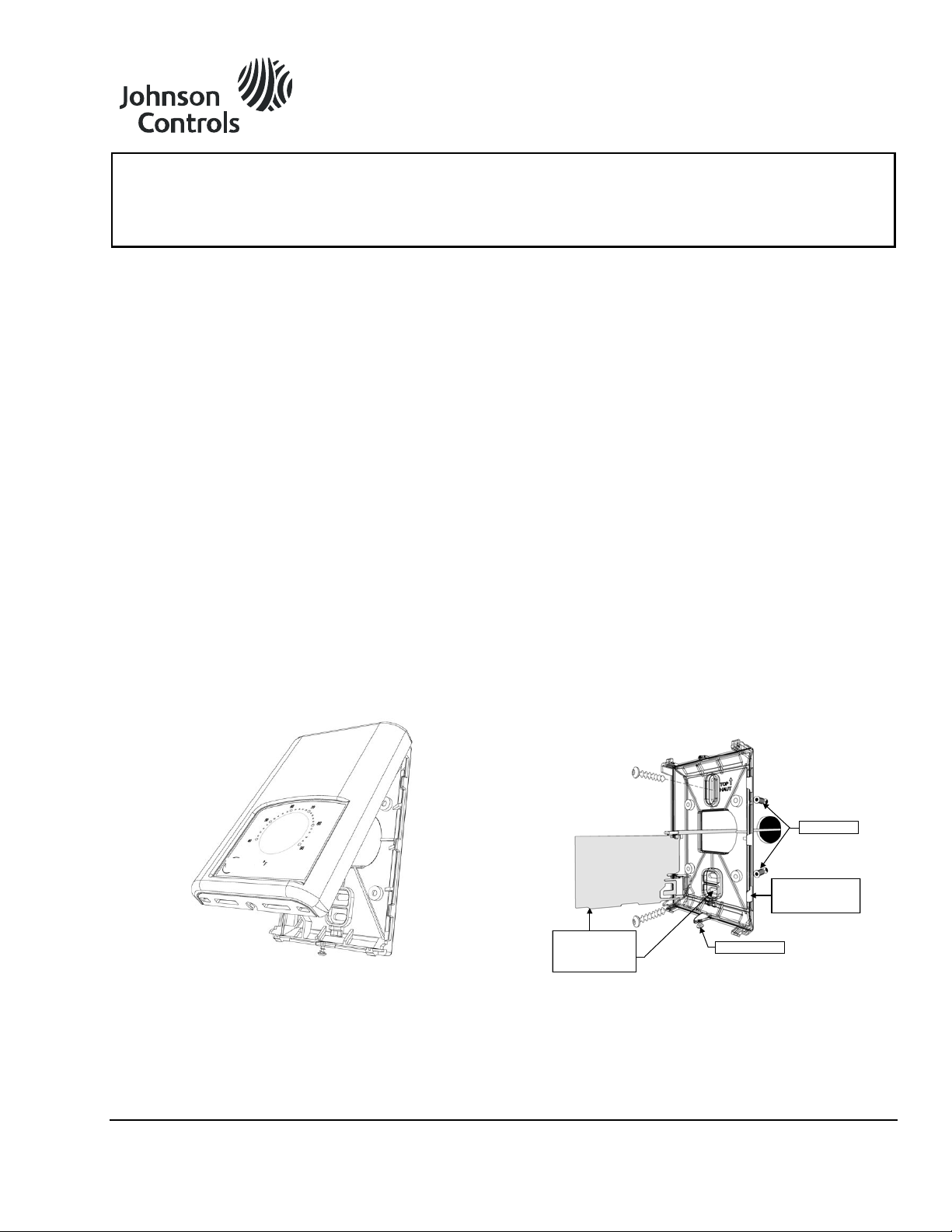
1. Remove security screw on the bottom of
thermostat cover.
2. Pull the bottom side of thermostat to open
(Figure 1).
3. Pull cables 6 inches out of the wall.
4. Insert cable in the central hole of the base.
5. Align the base and mark the location of the two
mounting holes on the wall. Install proper side of
base up.
6. Install anchors in the wall.
7. Insert screws in mounting holes on each side of
the base. Do not overtighten.
8. Strip each wire 1/4 inch.
9. Insert each wire ac cording t o wiring di agram.
10. Gently push excess wiring back into the hole in wall.
11. Press printed circuit board into place.
12. Install the cover, top side.
13. Install security screw.
Wall Anchor
Pull on plastic tab
to release the
printed circuit board
Figure 1: LN Series Sensor
© 2009 Johnson Controls, Inc.
Flip printed circuit
board to access
mounting hole
Figure 2: Sensor Installation
Security Screw
Code No. LIT-1201871 www.johnsoncontrols.com
1
Page 2
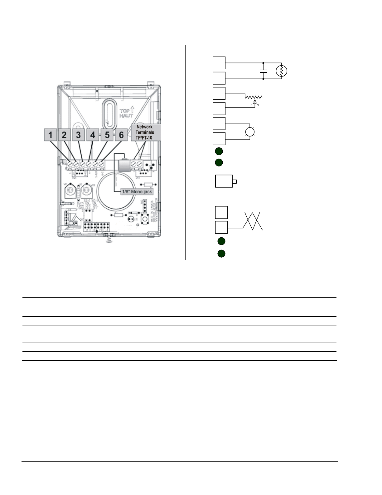
Wiring
Figure 3 shows the terminals. Generic Sensor wiring is
in Figure 4; please check Table 1 and Table 2 to verify
models.
CN1
CN2
1
2
3
4
5
6
1
2
Normally open
Momentarily closed
Override button
7
8
1/8 inch L
10K type 2 NTC thermistor
5% precision
10K DA setpoint potentiometer
20% tolerance
Resistance increases on CW
rotation
24 Vac / Vdc externally powered LED
for occupied / unoccupied system
ONWORKS Network Port Connnection
status
LONWORKS Network Terminals 1-2 TP-FT10
or Smart Sensor +/- remote connection via
L
ONWORKS Network Port
Figure 3: Terminals
Table 1: Sensor Functions
Part Number Sensor Temperature
Override
LN-SENSOR-0
LN-SENSLO-0
LN-SENOCW-0
LN-SENOSC-0
LN-SENOSF-0
X 1, 2, 7, 8
X X 1, 2, 5, 6, 7, 8
X X X 1, 2, 3, 4, 5, 6, 7, 8
X X X 1, 2, 3, 4, 5, 6, 7, 8
X X X 1, 2, 3, 4, 5, 6, 7, 8
± Scale
3
4
Figure 4: Sensor Wiring
C. Scale F. Scale Terminals
2 LN Series Sensors Installation Instructions
Page 3

r
Table 2: Sensor Models
Part Number Description
LN-SENSOR-0
LN-SENSLO-0
LN-SENOCW-0
LN-SENOSC-0
LN-SENOSF-0
LN-SENAV1-0
LN-SENAV2-0
Room sensor – no setpoint
Room sensor with LED, override push button
Room sensor with LED, override push button, and setpoint adjustment (cool/warm)
Room sensor with LED, override push button, and setpoint adjustment (°C)
Room sensor with LED, override push button, and setpoint adjustment (°F)
Room sensor containing four thermistors. Jumper configurable for averaging up to maximum of for
sensors connected in parallel. No setpoint.
Room sensor containing four thermistors. Jumper configurable for averaging up to a maximum of four
sensors connected in parallel. With LED and Override push button. No setpoint.
Averaging Sensors Wiring Examples Single Remote Room Sensor
1 x LN-SENAV2-0
Wiring 1 Sensor
S2 -1 = ON / S2 -2 = ON
Scom
RS
AU
C
D1
D2
ScomRSScom
RS
Aux
C
DI
LN-SENAV1-0
Wiring 1 Sensor
S2 -1 = ON / S2 -2 = ON
OR
OR
ScomRSScom
RS
Figure 5: Single Remote Room Sensor Wiring Example
Two Room Sensors for Averaging Applications
2 x LN-SENAV2-0
Wiring 2 sensors
S2 -1 = OFF / S2 -2 = ON
Scom
RS
AU
C
D1
D2
D2
1 x LN-SENAV1-0 and
1 x LN-SENAV2-0
Wiring 2 sensors
S2 -1 = OFF / S2 -2 = ON
Scom
RS
AU
C
D1
ScomRSScom
RS
Aux
C
DI
ScomRSScom
RS
Aux
C
DI
ScomRSScom
RS
Aux
C
DI
ScomRSScom
RS
Figure 6: Two Remote Sensors for Averaging Applications Wiring Example
ON
Dip switch
setting for:
1 senso
S2 -1 = OFF / S2 -2 = ON
Scom
RS
S2-1 = ON
S2-2 = ON
2
1
2 x LN-SENAV1-0
Wiring 2 sensor s
ScomRSScom
RS
AU
C
ON
2
1
S2-1 = OFF
S2-2 = ON
D1
D2
Notes for averaging ap plications:
LN-SENAV-1 and LN-SENAV2-0 can be mixed matched.
Wire LN-SENAV-1 and LN-SENAV2-0 in parallel.
Request the dip switch setting in each remote sensor.
Dip switch
setting for:
2 sensors
ScomRSScom
RS
LN Series Sensors Installation Instructions 3
Page 4

Three Room Sensors for Averaging Applications
D2
2 x LN-SENAV1-0 and 1 x LN-SENAV2-0
Scom
RS
AU
C
D1
Wiring 3 sensors
S2 -1 = OFF / S2 -2 = OFF
ScomRSScom
RS
Aux
C
DI
ScomRSScom
RS
ScomRSScom
RS
D2
1 x LN-SENAV1-0 and 2 x LN-SENAV2-0
Scom
RS
AU
C
Wiring 3 sensors
S2 -1 = OFF / S2 -2 = OFF
Scom
Scom
RS
RS
Aux
C
DI
D1
ScomRSScom
RS
Aux
C
DI
ScomRSScom
RS
Dip switch
setting for:
3 sensors
ON
2
1
S2-1 = OFF
S2-2 = OFF
Figure 7: Three Room Sensors for Averaging Application Wiring Example
Temperature versus Resistance Chart for 10 K ohm NTC Thermistor
ºC ºF K ohm ºC ºF K ohm ºC ºF K ohm ºC ºF K ohm ºC ºF K ohm
-20 -4 87.1310 -10 14 51.3490 0 32 31.1410 10 50 19.4020 20 68 12.3980
-19 -2 82.5330 -9 16 48.7820 1 34 29.6670 11 52 18.5320 21 70 11.8710
-18 0 78.2010 -8 18 46.3570 2 36 28.2700 12 54 17.7050 22 72 11.3690
-17 1 74.1190 -7 19 44.0650 3 37 26.9460 13 55 16.9190 23 73 10.8900
-16 3 70.2710 -6 21 41.8990 4 39 25.6910 14 57 16.1720 24 75 10.4340
-15 5 66.6420 -5 23 39.8490 5 41 24.5000 15 59 15.4620 25 77 10.0000
-14 7 63.2200 -4 25 37.9110 6 43 23.3710 16 61 14.7870 26 79 9.5858
-13 9 59.9910 -3 27 36.0770 7 45 22.3000 17 63 14.1450 27 81 9.1909
-12 10 56.9430 -2 28 34.3410 8 46 21.2840 18 64 13.5330 28 82 8.8143
-11 12 54.0660 -1 30 32.6970 9 48 20.3190 19 66 12.9520 29 84 8.4549
Metasys® and Johnson Controls® are registered trademarks of Johnson Controls, Inc.
All other marks herein are the marks of their respective owners. © 2009 Johnson Controls , Inc.
4 LN Series Sensors Installation Instructions
Building Efficiency
507 E. Michigan Street, Milwaukee, WI 53202
 Loading...