

Johnson Controls LB-FMS1655-F01, LB-FMS1655-F11, LB-FMS1655-F04, LB-FMS1655-F10, LB-FMS1655-F12 Installation Manual
...Page 1

FMS-1655 Room Pressure Controller (BACnet
®
/ N2 only products)
Installation Manual
LB-FMS1655-F01
LB-FMS1655-F02
LB-FMS1655-F03
LB-FMS1655-F04
LB-FMS1655-F10
LB-FMS1655-F11
LB-FMS1655-F12
LB-FMS1655-F13
Application
These installation instructions guide the installer through the installation of the FMS-1655 Room Pressure Controller.
Please read these instructions thoroughly before beginning installation.
North American Emissions Compliance
United States
This equipment has been tested and found to comply with the limits for a Class A digital device pursuant to Part 15 of the FCC
Rules. These limits are designed to provide reasonable protection against harmful interference when this equipment is operated
in a commercial environment. This equipment generates, uses, and can radiate radio frequency energy and, if not installed and
used in accordance with the instruction manual, may cause harmful interference to radio communications. Operation of this
equipment in a residential area may cause harmful interference, in which case users will be required to correct the interference
at their own expense.
LB-FMS1655-S01
LB-FMS1655-S02
LB-FMS1655-S03
LB-FMS1655-S04
LB-FMS1655-T01
LB-FMS1655-T02
LB-FMS1655-T03
LB-FMS1655-T04
Code No. LIT-12013117, Rev. A
Issued August 2018
Canada
This Class (A) digital apparatus meets all the requirements of the Canadian Interference-Causing Equipment Regulations.
Cet appareil numérique de la Classe (A) respecte toutes les exigences du Règlement sur le matériel brouilleur du Canada.
Installation
NOTICE
Risk of Property Damage.
Ensure that the power source conforms to the requirements of the equipment. Failure to use a correct power source may
result in permanent damage to the equipment.
NOTICE
Risque de dégâts matériels.
S’assurer que la source d’alimentation électrique est conforme aux spécications de l’équipement. L’utilisation d’une source
d’alimentation électrique inappropriée risque d’endommager irrémédiablement l’équipement.
IMPORTANT: The FMS-1655 Room Pressure Controller must be wired to 24 VAC only. Wiring the unit to 110 VAC will cause
serious damange and void the warranty.
Use of the software that is in (or constitutes) this product or access to the cloud or hosted services applicable to this product,
if any, is subject to applicable terms set forth at www.johnsoncontrols.com/techterms. Your use of this product constitutes an
agreement to such terms. If you do not agree to be bound by such terms, you may return the unused product to your place of
purchase.
Central Monitoring Station
The Next Generation in Critical Airow Controls
Room Pressure Controller
JCI CMS-1655
JCI FMS-1655
JCI FMS-1655
Page 2

Notes
Page 3
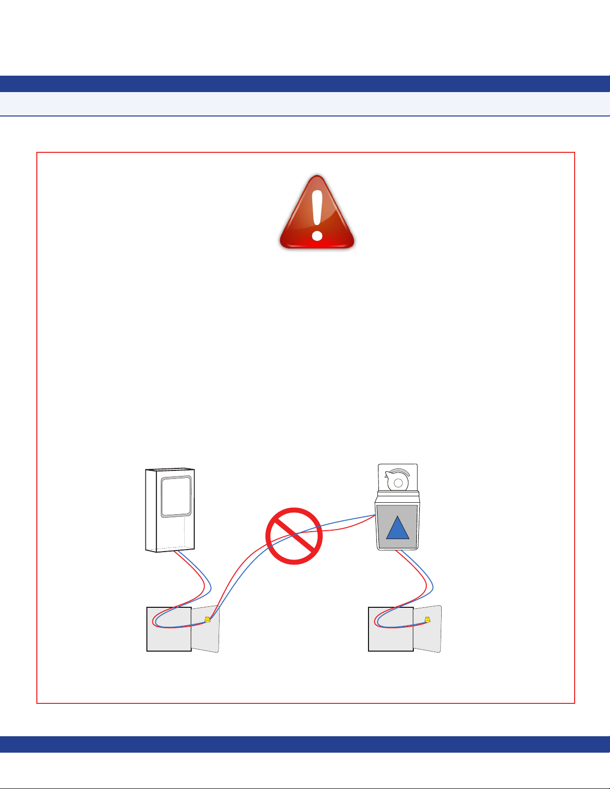
Warning
Failure to follow the wiring diagrams could result in damage to your equipment and could void your warranty.
Under no circumstances should a single transformer be split between actuator and controller. Doing so
will damage the actuator, the transformer, the controller or all units. A single 120/24V 30Va transformer
is required for the controller and a separate 120/24V 20Va transformer is required for the actuator. This
equipment contains electrostatic sensitive components. To prevent possible damage, take precautions to
prevent electrostatic discharge when handling or servicing this equipment by wearing an approved ESD
grounding wrist strap connected to an earth ground source.
Controller
FAST ACTING
ELECTRONIC ACTUATOR
CORRECT
120/24VAC, 30Va Transformer
Supplied by JCI
Due to continuous improvement, TRIATEK reserves the right to change product specifications without notice.
120/24VAC, 20Va Third Party
Transformer
Actuator
CORRECT
Page 4

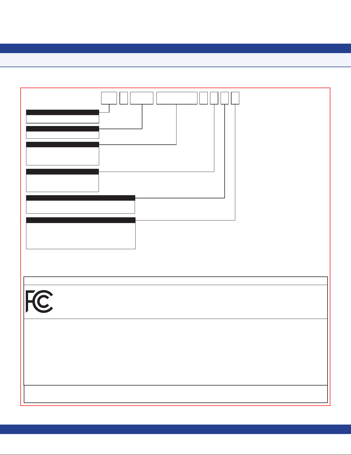
CONTROLLER SETTINGS
FMS-1655 Room Pressure Controller Settings
This form should be completed during the initial configuration for each room pressure controller. Be sure to configure the unit
for either Positive, Negative, or both using the Isolation Mode Configuration setup procedure.
Room Name / Number
Unit Model Number and Serial Number (ESN)
Analog Input
Normal Operating Pressure (reading with door closed)
Sensor Input Mode (normal or inverted)
Sensor Input Range (zero-based or offset)
Sensor Pressure Range
Positive Isolation Setpoint
Negative Isolation Setpoint
Neutral Isolation Setpoint
Pressure Deadband
Analog Output
Operating Mode (Direct or PID)
Analog Output Range (zero-based or offset)
Analog Output Upper Limit (0 – 100%)
Analog Output Lower Limit (0 – 100%)
Analog Output Input Channel (AI-1 thru AI-4, TI-1 or TI-2)
Analog Output Action (Direct or Reverse)
Analog Output Range (zero-based or offset)
Door Switch
Operating Mode (normally-open or normally-closed)
Delay Setting (0 - 240 secs)
Relay Output
Trigger Mode (Setpoints, Isolation Mode or Occupancy)
Input Channel (AI-1 thru AI-4, TI-1 or TI-2)
Positive Isolation High Setpoint
Positive Isolation Low Setpoint
Page 5

Negative Isolation High Setpoint
Negative Isolation Low Setpoint
Relay Acting Mode (Direct or Reverse)
Delay Setting (0 - 180 secs)
PID Constants
Proportional Constant (0.5 – 100.0 %)
Integral Constant (0.0 – 100.0 %)
Derivative Constant (0.0 – 100.0 %)
Alarm Limits
Positive Isolation High Alarm Setpoint
Positive Isolation High Warning Setpoint
Positive Isolation Low Warning Setpoint
CONTROLLER SETTINGS
FMS-1655 Isolation Room Pressure Controller Settings
Positive Isolation Low Alarm Setpoint
Negative Isolation High Alarm Setpoint
Negative Isolation High Warning Setpoint
Negative Isolation Low Warning Setpoint
Negative Isolation Low Alarm Setpoint
Audible Alert
Enabled Input Channels (AI-1 thru AI-4, TI-1, TI-2)
Operating Mode (audible or silent)
Delay Time Base (secs or mins)
Delay Setting (0 – 60)
Alarm Quiet Period Starting Hour (0 – 23)
Alarm Quiet Period Ending Hour (0 – 23)
Engineering Units
Inches of Water or Pascals
Due to continuous improvement, TRIATEK reserves the right to change product specifications without notice.
Page 6

INSTALLATION MANUAL
Table of Contents
GENERAL
Specifications………………………………………………………………………………...……………………………………………1 - 2
Part Number Guide…………………………………………………………………………………………………………………………2
Overview……………………………………………………………………..…………………….………………………………………3 - 4
MOUNTING/WIRING
FMS-1655 Flush Mount With Internal Sensor
Introduction…………………………………………………………………………………………………………………………………5
Mounting Procedure………………………………………………………………………………………....……………………………5 - 6
Internal Sensor Illustration………………………………………………………………………….....……………………………………7
FMS-1655 With Remote Sensor
Introduction…………………………………………………………………………………………………………………………………9
Mounting Procedure………………………………………....………………………………………………………………………………9
FMS-1655 With Standard Remote Sensor Illustrations………………………………………………………………………....…10 - 11
Remote Sensor Configuration Illustration……………………………………………………………………………………………..12
Analog Output to Electric and Pneumatic Damper Actuator Illustrations (Internal Sensor Model)………………....………13 - 14
Analog Output to Variable Speed Drive Illustration (Internal Sensor Model)………………………………………………..………15
Analog Output to Modulated Air Controller Illustration (Internal Sensor Model)……………………………………………………16
Analog Output to Pneumatic Damper Actuator Illustration (Internal Sensor Model)………………………………………………17
Analog Output to Variable Speed Drive Illustration……………………………………………………………………………………18
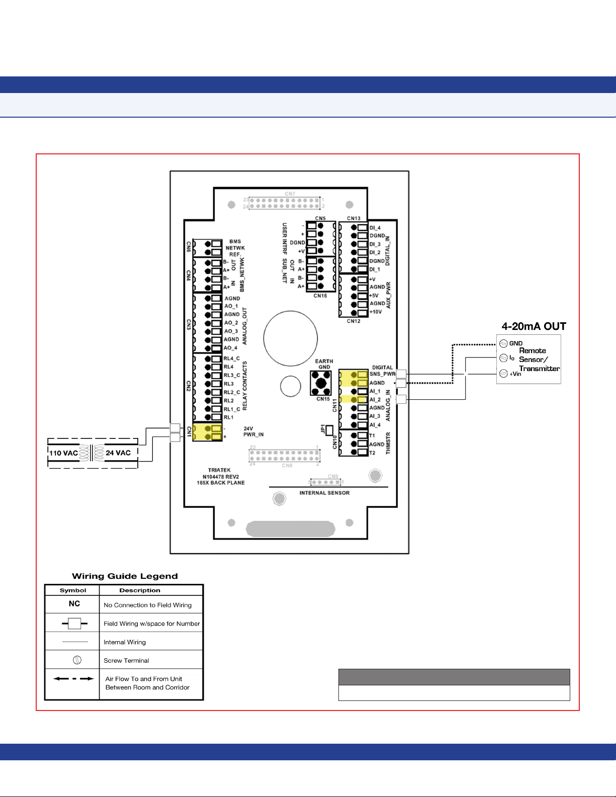
Adding Remote Pressure Sensor with 4-20mA Out to Internal Sensor Model Illustration……………………………………19
Analog Input to 2 Remote Pressure Sensor 4-20mA Out Illustration……………………………………………………………… 21
Analog Input to 3 Remote Pressure Sensor 4-20mA Out Illustration……………………………………………………………… 22
Analog Input to 4 Remote Pressure Sensor 4-20mA Out Illustration……………………………………………………………… 23
Analog Input to Temperature Sensor Illustration……………………………………………………………………………………… 24
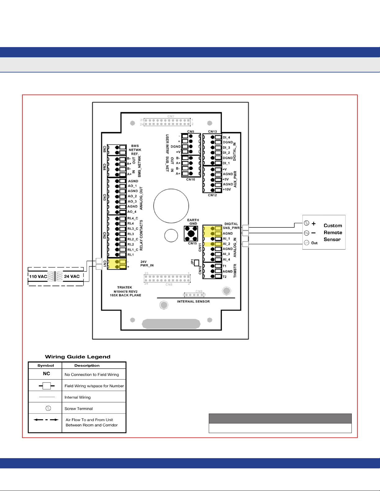
Custom Sensor Illustration………………………………………........................................................................……………………25
Digital Input to Door Switch Illustration………………………………………………………………………………………………… 26
Digital Input to Occupancy Sensor……………………………………………………………………………………………………28
Relay Output Alarm Illustration………………………….………………………………………………………………………………29
Relay Output to Warning Illustration……………......…………………………………………………………………………………30
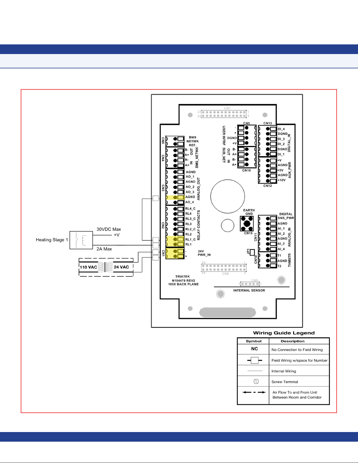
Relay Output 1 Illustration…………………........………………………………………………………………………………………31
Relay Output 2 Illustration………………........……....…………………………………………………………………………………32
Power Illustration……………………………...….…………………………………………………………………………………………33
Isolated Power Supply………………………..……………………………………………………………………………………………34
COMMUNICATIONS - BACnet MS/TP
Wiring Illustration………………………………………………………………………………………………………...…………………36
COMMUNICATIONS - METASYS N2 OPEN
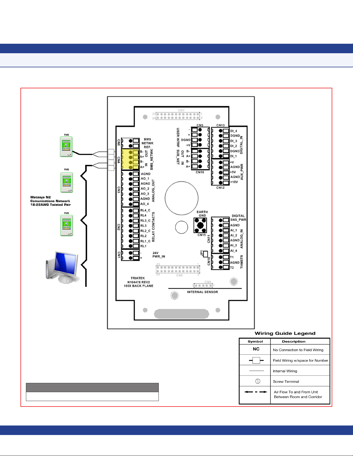
Wiring Illustration…………………………………………………………………………………………………....………………………37
FMS-1655 QUICK START GUIDE
Quick Start Guide………………………………………………………………………………………………………....………………38
Main Display Screen………………………………………………………………….....…………………………………………………38
Automated Clean Cycle ………………………………………………………………...……………………………………………38 - 39
Configuring Room Pressure Monitor…………………………………………......………………………………………………………39
Setting Up Analog Output………………………………………………………..………………………………………………………39
Enabling Door Switch………………………………………………………………………………………………………………39 - 40
Setting Up Alarm Relay Output....……………………………………………….………………………………………………………40
Setting Alarm Limits...…………………………………………..…………………………………………………………………………40
Changing Isolation Mode.……………………………………..........……………………………………………………………………40
Page 7

INSTALLATION MANUAL
Table of Contents
Invoking Auto Clean Cycle.………………………………..........…………………………………………………………......……….....40
Changing Network Settings..………………………….....…………………………………………………………………………………40
Adding Password Security…………………………...……………………………………………………………………………………40
Changing Display Settings……………….……………………………………………………………………………......…………40 - 41
Built-in Diagnostics………………………...………………………………………………………………………………………………41
MODULE SETTINGS
Configuring Display Module Settings……………………………...……………………………………………………………………43
Configuring Main Controller Module Settings………....………………………………………………………………………………44
Configurations and Settings………………………………………………………………………………………………………………45
BACnet® OBJECTS
Analog Input Objects………………………...…….………………………………………………………………………………………46
Analog Output Objects……………………..……...………………………………………………………………………………………46
Binary Input Objects………………………..……..………………………………………………………………………………………46
Binary Output Objects……………………....………..……………………………………………………………………………………46
Analog Value Objects……………………....…………..……………………………………………………………………………46 - 47
Multistate Output Objects……………..………………...…………………………………………………………………………………47
METASYS® N2 OBJECTS
Analog Input Objects…………………………....…………………………………………………………………………………………48
Analog Output Objects……………………….....…………………………………………………………………………………………48
Binary Input Objects……………………………...………………………………………………………………………………………48
Binary Output Objects………………………….....………………………………………………………………………………………48
Internal Float Value Objects………………………..………………………………………………………………………………48 - 49
Multistate Output Objects……………………….....………………………………………………………………………………………49
CLEANING THE DISPLAY
Cleaning the FMS-1655……………………….....………………………………………………………………………………………51
DIAGRAMS
Wiring Illustration……………………………………………………………………......…………………………………………………52
Integrated Flush Mount Wiring Box Dimensions………………....……………………………………………………………………53
Flush Mount Bracket Dimensions………………………………………………………………………………………………………54
Thin Mount Wiring Box Dimensions……………………..………………………………………………………………………………55
FLOW DIAGRAMS
Unit Setup Tree………………………………….....………………………………………………………………………………………57
System Setup Tree……………...……………………………………………………………………………………………………58 - 60
Display Setup Tree…………....……………………………………………………………………………………………………………61
Diagnostics Tree………………..…………………………………………………………………………………………………………62
Due to continuous improvement, TRIATEK reserves the right to change product specifications without notice.Due to continuous improvement, JCI reserves the right to change product specifications without notice. Due to continuous improvement, JCI reserves the right to change product specifications without notice.
Page 8

GENERAL
Specications
Electrical
Optional External Remote Sensor Distance……………………………………………………………………………………………………Up to 1,000 feet
Optional External Remote Sensor....………………………………………………………………………………Wiring 18-22 AWG, shielded twisted pair
Power Supply..…………………………………………………………………………………………………………………………………24 Vac ±10%, 30Va
Accuracy of Measurement.....……………………………………………………………………………………………………………………………±0.5%FS
Pressure Range (NIST Traceable / Individual certication available as option)…………………………………………………………………±0.2500 “WC
Pressure/Flow……………………………………………………………………………………………………………………………………up to 0.25 ”WC
4 Analog Inputs…………………………………………………………………………………………………………………4-20mAdc, 0-5Vdc or 0-10Vdc
4 Analog Outputs………………………………………………………………………………………………………………4-20mAdc, 0-5Vdc or 0-10Vdc
2 Thermistor Inputs…………………………………………………………………………………………………………NTC Type 2 or 3, 10kΩ @ 25°C
4 Digital Inputs………………………………………………………………………………………………0-5Vdc or 0-24Vdc, Active-High or Active-Low
3 Relay Outputs...………………………………………………………………………………………………………………………………………1A@24Vdc
Control Signal Wire Size............……………………………………………………………………………………………………………………18-22 AWG
Power Supply………………………Class 2, 24Vac ±10%, 30VA universal 120/240 to 24 Vac, 60/50 Hz, step-down isolation transformer provided
Communications
BACnet® MS/TP network....…………………………………………………………………………………………Two-Wire Twisted Pair, RS-485 signaling
Metasys N2 network...………………………………………………………………………………………………Two-Wire Twisted Pair, RS-485 signaling
Recommended Cable Type...……………………………………………………………………………………………………………………… Belden 3107A
Touchscreen User Interface
LCD Size....……………………………………………………………………………………………………………………………………………3.2” diagonal
LCD Type.....……………………………………………………………………………………………………………………………………………Transmissive
Resolution...………………………………………………………………………………………………………………………………………240 x 320 portrait
Viewing Area..……………………………………………………………………………………………………………………………50.60 mm x 66.80 mm
Color Depth.…………………………………………………………………………………………………………………………………18-bit or 262K colors
Backlight Color.....………………………………………………………………………………………………………………………………………………White
Luminous Intensity...………………………………………………………………………………………………………………………………Min 2500 cd/m2
Recommended Cable Type (applicable to surface mount models FMS-1655-s-x only)…………………………………………………… Belden 3125A
Mechanical
FMS-1655 Internal Sensor Flush Mount Housing (Brushed Stainless Steel) Housing..……………………………………………5.6”W x 8.5”H x 1.9”D
FMS-1655 Display Module Housing………………………………………………………………………………………………………3”W x 5”H x 1.13”D
Stainless Steel Cover Plate for Flow Tube……………………………………………………………………………………………2.7”W x 4.5”H x 0.2”D
Stainless Steel Cover Plate for Remote Sensor………………………………………………………………………………………2.7”W x 4.5”H x 0.2”D
FMS-1655 with Flow Tube Cover Plate……………………………………………………………………………………………………………approx. 3.5 lb
FMS-1655 with Optional External Remote Sensor………………………………………………………………………………………………approx. 4.0 lb
FMS-1655 Mounting Options...……………………………………………………………………………………………………………………Surface, Flush
Flow Tube Cover Plate Mounting.. ……………………………………………………………………………………………………………………………Flush
Environmental
Operating Temperature..…………………………………………………………………………………………………………………32° to 125° F Operating
Operating Humidity……………………………………………………………………………………………………………10% - 95% RH, Non-condensing
- 1 -
Due to continuous improvement, JCI reserves the right to change product specifications without notice.
Page 9
- -
BRAND
LB = Johnson Controls
UNIT
FMS = Flow Monitor Station (FMS)
SERIES
1655 = BACnet / N2 Controller
1655L = LonWorks Controller
1655M = BACnet Monitor
STYLE
S = Surface mount
F = Flush mount
T = Thin mount
INTERNAL SENSOR
0 = No internal sensor
1 = Standard internal sensor
REMOTE SENSOR
0 = No remote sensors
1 = One remote sensor
2 = Two remote sensors
3 = Three remote sensors
4 = Four remote sensors (Not available with LonWorks Controllers)
(BACnet / N2 controllers only)
(Flush mount controller only)
(Not available with LonWorks Controllers)
GENERAL
Specications
FCC Compliance Statement
This device complies with Part 15 of the FCC Rules. Operation is subject to the following two conditions:
• This device may not cause harmful interference, and
• This device must accept any interference received, including interference that may cause undesired operation.
Please Note: This equipment has been tested and found to comply with the limits for a Class A digital device, pursuant to Part 15 of the FCC Rules.
These limits are designed to provide reasonable protection against harmful interference in a commercial installation. This equipment generates, uses and can
radiate radio frequency energy and, if not installed and used in accordance with the instructions, may cause harmful interference to radio communications.
However, there is no guarantee the interference will not occur in a particular installation. Operation of this equipment in a residential area is likely to cause
harmful interference in which case the user will be required to correct the interference at his own expense.
Caution: To comply with the limits for an FCC Class A computing device, always use the isolated power supply module and recommended interface
cables with this unit.
The Federal Communications Commission warns that changes or modifications to the unit not expressly approved by the part responsible for compliance could
void the user’s authority to operate the equipment.
This Class-A digital apparatus complies with Canadian ICES-003.
Cet appareil numérique de la classe-A est conforme à la norme NMB-003 du Canada.
- 2 -
Due to continuous improvement, TRIATEK reserves the right to change product specifications without notice.Due to continuous improvement, JCI reserves the right to change product specifications without notice.
Page 10

GENERAL
Overview
The JCI FMS-1655 Room Pressure Controller
is an ultra-sensitive instrument used to
monitor and/or control air pressure in hospital
rooms, labs, and clean rooms. This unit
is capable of measuring and displaying
differential air pressures as low as 0.0001
“WC or 0.0249 Pa. The FMS-1655 may be
used to control differential pressures down to
0.0040 ”WC or 1 Pa.
Key features of the FMS-1655 include:
• Full-color touchscreen display with
programmable display options and
adjustable backlight
• Intuitive user interface simplifies setup
and configuration of unit
• Display background changes color to
indicate room status at a glance
• Patented Safety Halo™ with color-coded
180° edge lighting
• Automated clean cycle with fully
programmable duration for quick
turnaround of patient or isolation room
• Audible and visual alarm annunciation
• Internal or remote sensor options
available with up to four sensors total
(one internal, three remotes OR four
remotes)
• Auxiliary universal analog inputs for use
with optional sensors
• Four independent PID control loops for
controlling damper actuators, speed
drives, hot water valves, humidifiers, etc.
• Digital input used to monitor the door
switch of the monitored room
• Relay outputs used for transmitting alarm
condition to remote location
• Dedicated thermistor inputs for
temperature control applications
• Multi-level password protection of
touchscreen user interface
• Zero calibration feature allows in-field
recalibration of zero pressure reading
• Multi-protocol native (BACnet® or
Metasys® N2) for easy integration with
any BMS
• Manual override of analog and relay
outputs assist with test and balance
procedures
• Comprehensive real-time view
• Built-in diagnostics tool
• Easy-to-install backplane/backplate
assembly facilitates permanent
termination of all wiring
The FMS-1655 features enhanced graphics
the patented Safety Halo.™ This simple yet
elegant feature significantly enhances the
alarm status indication of the FMS-1655 by
providing full 180-degree visibility. The Safety
Halo™ is shipped from the factory enabled at
full brightness, but may be dimmed or even
disabled completely from the display setup
menus.
The FMS-1655 is equipped with a 3.2”
diagonal full-color touchscreen display
in portrait orientation (240 x 320). The
password-protected menu tree is very intuitive
and simplifies the setup and configuration of
the unit. The menus incorporate touch-based
interfaces such as sliders, radio buttons, and
dialog popups to facilitate the ease-of-use of
the FMS-1655.
The display implements bright graphical color
changes to indicate the three different alarm
status indications of the monitored isolation
room. These graphical backgrounds indicate
“Normal” when the differential pressure is
within defined limits, “Warning” when the
differential pressure is approaching an
out-of-limits condition, and “Alarm” when the
differential pressure is outside the defined
acceptable and safe limits.
The differential pressure ranges for these
conditions are easily configured by the user
for the specific installation when necessary,
either directly from the touchscreen display or
over the network from the BMS. The graphical
background changes provide an at-a-glance
overview of the monitored isolation room
differential pressure conditions.
Alarm conditions may be defined by the
user, in terms of desired differential pressure
settings for the room being monitored.
When an alarm condition occurs, it may be
annunciated in four user-definable ways:
1) on the display, 2) with an audible alarm,
and 3) transmitted via contacts to a remote
monitoring station and 4) over the BMS
network. The alarm will automatically reset
when the unit has sensed that the room
differential pressure has returned to proper
limits. The attendant may easily mute the
audible alarm by touching the alarm audible
button on the bottom of the display.
For many applications, it is important to have
other variables such as anteroom differential
pressure or relative humidity displayed along
with the isolation room differential pressure.
The FMS-1655 provides for this by means of
three additional universal analog inputs, which
may be configured for either current loop
operation or voltage input operation. Each
input may be scaled as needed to display
correct values, and may have an engineering
units selection associated. The configuration
of each analog input is field selectable
through the use of miniature dipswitches on
the controller unit.
- 3 -
Due to continuous improvement, JCI reserves the right to change product specifications without notice.
Page 11

GENERAL
Overview
For those applications requiring monitoring
and/or control based on temperature
variances, the FMS-1655 provide two
dedicated thermistor inputs in addition to the
four universal analog inputs. Therefore, a total
of six analog inputs are available for control
applications. The two thermistor inputs may
be used with negative temperature coefficient
(NTC) Type 2 or Type 3 sensors.
The FMS-1655 provides four universal
analog outputs, which may be configured for
either current loop operation or for voltage
operation.
Each analog output may be configured for
proportional operation to provide a linear
signal to the BMS, or for PID (proportionalintegral-derivative) control operation for
closed-loop feedback control of damper
actuators, variable frequency (speed) drives,
hot water valves, humidifiers, or other analogcontrolled devices.
Each universal analog output may be fieldconfigured for the required application using
onboard configuration dipswitches on the
controller module. Each analog output may
also be temporarily overridden using the builtin diagnostic tools for troubleshooting during
the installation and commissioning phase.
The FMS-1655 provides four digital inputs that
may be used for monitoring door switches,
override switches, or other devices with binary
outputs. The configuration and operation of
each input may be configured by the user to
define the effect of a change in its state. Each
digital input may have a programmable delay
duration associated with it. Each digital input
may be configured for either normally-closed
or normally-open operation, and may also
be configured to be active-high or active-low
triggered. The global configuration of the
digital inputs is field selectable through the use
of miniature dipswitches on the controller unit.
The FMS-1655 provides three relay outputs,
which may be configured for either directacting or reverse-acting operation, and may
have a programmable delay associated
to meet the specific needs of the required
application.
A unique feature of the FMS-1655 is its ability
to trigger a relay output based on the current
mode of isolation, thereby providing support
for transfer grilles, supplemental exhaust
dampers, etc. Each relay output may also
be temporarily overridden using the built-in
diagnostic tools for troubleshooting during the
installation and commissioning phase.
The user may set up multiple multi-level
passwords to prevent unauthorized or casual
access to the FMS-1655 configuration
settings. Up to 10 passwords of up to eight
digits may be programmed, with each
having one of four associated access levels.
Administrators and facility management
personnel may have unrestricted access,
while general staff may be assigned restricted
access passwords which limit the functionality
of the user menus.
Room pressure selection of positive, negative,
or neutral isolation may be protected using
limited access passwords, thereby eliminating
the need for keylock switches and keys.
An optional keylock switch may be used to
further control access to change in isolation
modes. In some locales, it is prohibitive to
allow an isolation room controller to switch
between positive and negative modes of
isolation. To accommodate this situation, the
FMS-1655 may be configured at the factory
for either positive- and neutral-isolation modes
only or negative- and neutral-isolation modes.
The FMS-1655 provides native support for
multiple networking protocols, including
BACnet® MS/TP and Metasys® N2 Open.
With multi-protocol native support, the FMS1655 is able to communicate room status
information to the building automation system,
regardless of which protocol is used. (For
applications requiring LonWorks® networking
capability, contact the factory about JCI’s
FMS-1655L series) The configuration of the
desired protocol is field selectable through the
use of miniature dipswitches on the controller
unit.
The FMS-1655 provides a unique set of
built-in diagnostics tools that are extremely
valuable for facilitating the troubleshooting
process during the installation and
commissioning phase.
Included in these built-in diagnostics tools
are manual override capabilities for both
analog outputs and relay outputs, and a
comprehensive real-time view capability that
allows the real-time values and states of each
analog and digital input and output to be
displayed conveniently. This is an extremely
useful tool that facilitates the verification
and certification processes conducted by
typical test and balance personnel during the
commissioning of the system.
There are also options for storing configuration
settings and for restoring those settings, as
well as performing a complete restoration of
the factory default configuration settings.
The FMS-1655 incorporates an innovative
backplane/backplate assembly which greatly
facilitates the installation process and permits
all wiring terminations to be permanent.
The FMS-1655 serves as a direct drop-in
functional replacement for all previous models
of the FMS-1600 series of isolation monitors.
- 4 -
Page 12

MOUNTING/WIRING
FMS-1655 Flush-Mount with Internal Sensor
Introduction
The FMS-1655 flush-mount model has an
integrated internal sensor and should be
installed outside of the isolation room to be
monitored in the corridor wall. Sensor tubing
should be between this corridor and isolation
room in the most direct and shortest path.
The FMS-1655 is calibrated with configuration
settings programmed at the factory according
to the customer specifications, if provided.
Otherwise, each unit is shipped with factorydefault configuration settings. The user
may change these settings by following the
procedures outlined in the configuration/
programming section of this manual.
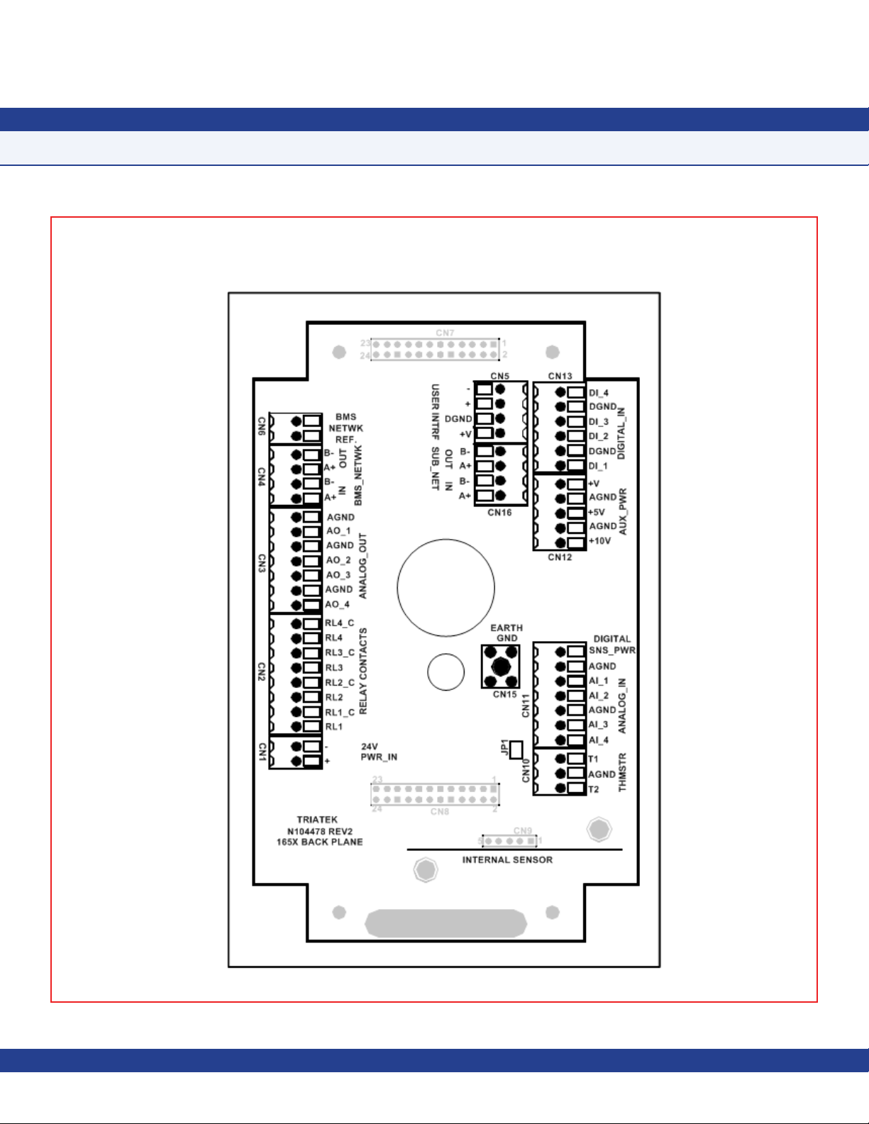
The electrical connections to the FMS-1655
are made via convenient terminal block
connectors on the backplane/backplate
assembly as shown on page 7. All wiring
should conform to local regulations and to the
National Electrical Code (NEC). Precautions
must be taken to avoid running sensor wiring
in the same conduit as line voltage or other
conductors that supply highly inductive loads
such as generators, motors, solenoids,
contactors, and other sources of induced
noise. Use 22 AWG or larger for all electrical
wiring terminations.
Following the proper installation of the FMS1655, apply power to the unit and confirm
that you hear a brief chirp at the touchscreen
display, which indicates that the display
module is communicating with the controller
module.
There will be a six second power up delay
during which the Safety HaloTM will cycle
through the following colors: red, green, blue,
yellow, magenta, cyan, and white. After this
power up delay, the unit will display a brief five
second animation of the action icons, followed
by the FMS-1655 splash screen. This
splash screen displays the model number,
electronic serial numbers, firmware version
numbers, protocol selection, and current
network address. The splash screen remains
displayed for about 15 seconds, and then
proceeds to the main differential pressure
screen.
Mounting Procedure
1. Choose a location free of airflow
obstructions, and minimal air turbulence.
The installation should also avoid stagnant
air or “short circuiting” of the supply air to the
exhaust. Typically, the FMS-1655 should be
installed at eye level. It should be mounted
in a location that provides convenient access
such that the display may be viewed with
minimal glare and the touchscreen is easily
accessible to facilitate silencing the unit in the
event of an alarm.
The FMS-1655 is pre-configured at the factory
with the Safety Halo™ status indicator bezel
connected to the internal circuitry on the
display board, and has been tested for proper
operation. The Safety Halo™ should not be
removed from the flush mount faceplate, as it
may damage the internal circuitry and/or the
bezel itself. Attempting to separate the Safety
Halo™ from the flush mount faceplate will
void the manufacturer’s warranty.
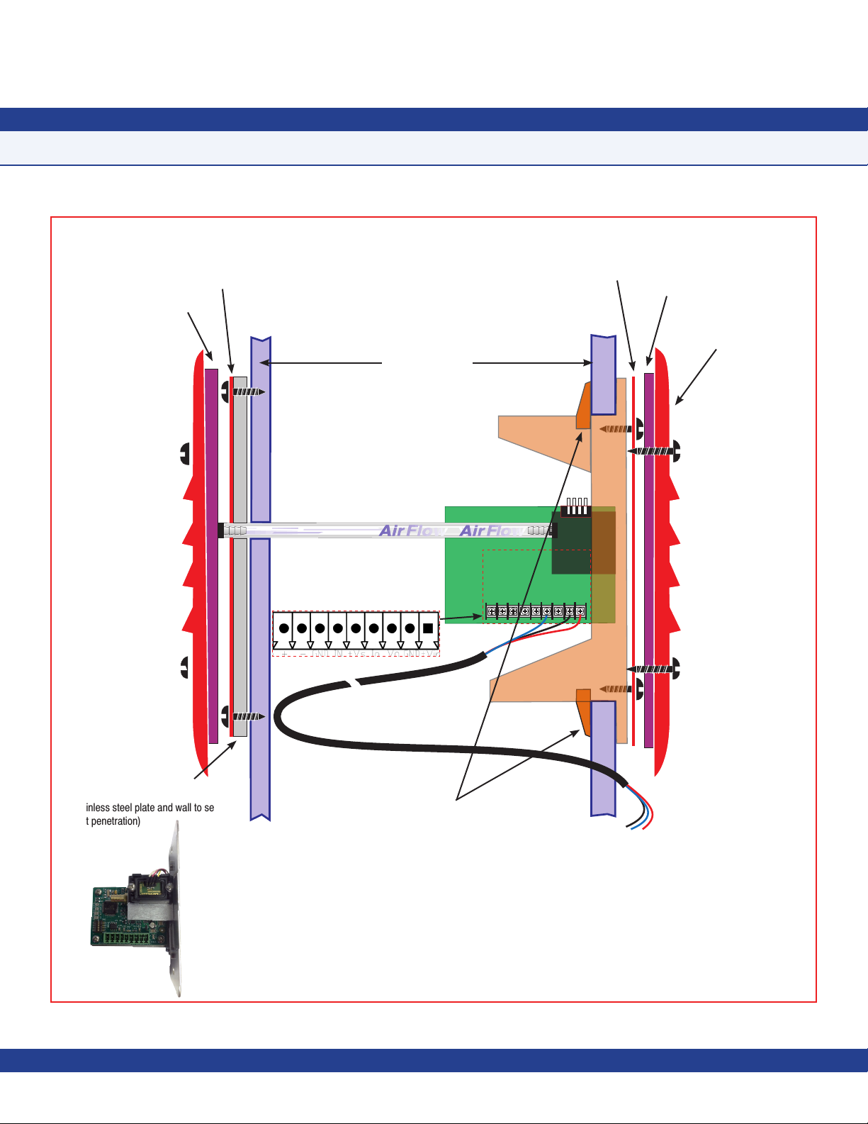
2. Before disassembling the flush-mount
electronics assembly, locate the clear
pressure tubing that extends from the lower
corner of the metal backplate to the nipple at
the inside face of the bottom of the faceplate
and disconnect it. The other end of this tubing
should remain attached to the right-angle
barbed fitting at the lower corner of the metal
backplate.
3. Disassemble the flush-mount electronics
assembly by grasping the metal backplate
and pulling it apart from the faceplate.
The metal backplate is attached to the
backplane subassembly which incorporates
all of the wiring termination points.
4. Run the conduit and all wiring according to
local regulations and National Electrical Code.
IMPORTANT: Use the 24 VAC stepdown
isolation transformer, provided with the
unit, to power the FMS-1655; this will
prevent inadvertent ground loop issues and
other problems that might otherwise be
encountered.
5. Pull slack from the tube on the opposite
side of the wall as the backplane/backplate
assembly is moved toward the wall for
mounting. On the opposite side, the return
air stainless base and louvered plate must be
mounted as shown on page 10. Caulk behind
the stainless mounting plate so that there may
be no air flow through the wall. Mount the
backplane/backplate assembly to the wall with
the appropriate screws (and wall anchors if
using the alternate installation method).
- 5 -
Due to continuous improvement, TRIATEK reserves the right to change product specifications without notice.
Page 13

6. Terminate all electrical connections at the
backplane taking note of the terminal labels.
Note that the power connector is distinguished
as it is of a different color and separated
from the other connectors. The 45-degree
positioned wire openings on the connectors
should greatly facilitate the wire termination
process.
7. On the opposite side of the wall, a length
of pressure tubing will be protruding from
the wall. Cut the tubing as needed to leave
approximately two inches protruding. Press
the tubing onto the barbed fitting of the flow
tube mounting plate (see page 10). Push
the mounting plate and tube toward the
wall, forcing the excess into the wall space.
Fasten the mounting plate to the wall using
appropriate hardware.
MOUNTING/WIRING
SUBHEAD
FMS-1655 Flush-Mount with Internal Sensor
8. Mount the louvered stainless steel cover
plate to the mounting plate with the screws
supplied.
9. Apply power to the FMS-1655 and confirm
that following a brief initialization sequence,
the unit displays the room differential pressure
and the Safety Halo™ status matches that of
the main display screen. FMS-1655 units are
shipped from the factory in neutral isolation
mode.
- 6 -
Page 14
MOUNTING/WIRING
Internal Sensor
The FMS-1655 is calibrated with settings programmed in the factory according to the customer specifications. The user can change the settings
by using the instructions provided in the Quick Start section of this manual beginning on page 38.
- 7 -
Page 15

MOUNTING/WIRING
Notes
- 8 -
Due to continuous improvement, TRIATEK reserves the right to change product specifications without notice.
JCI reserves the right to change product specifications without notice.
Page 16

MOUNTING/WIRING
FMS-1655 With Remote Sensor
Introduction
The flexibility of the FMS-1655 provides for
several different configurations with respect to
the sensor location.
FMS-1655 models without an internal
sensor include at least one remote sensor
for measuring the differential pressure of the
monitored room. This remote sensor module
must be installed in the wall between the
monitored isolation room and the adjoining
corridor or anteroom.
The remote sensor module should be installed
with the attached stainless steel mounting
plate facing the isolation or patient room and
the reference plate facing the corridor or
anteroom. Please see illustrations on pages
10 and 11 for more details.
With this sensor orientation, a positive
pressure value indicates that the isolation
room is positive with respect to the corridor.
A 3-conductor (22 AWG) cable MUST be
connected between the remote sensor
module and the main controller module for
each sensor included with the unit. The length
of this cable should not exceed 1,000 feet.
The display unit may be installed outside
the room, at the nurses’ station, in the
engineering office, or at any other location as
needed.
Mounting Procedure
1. Cut an opening in the wall of the isolation
room to receive the supplied low voltage
mounting bracket for the remote sensor
electronics. Nominal hole dimensions are
3.65” H x 2.15” W.
2. Drill a 7/16” hole through the opposite wall
for the flow tube as shown.
3. Bring the 3-conductor signal wire through
the cut out.
4. Install the included low-voltage mounting
bracket in the drywall opening, and pull
the 3-conductor signal cable through the
mounting bracket.
5. Push a length of flow tube through the back
hole on through the 7/16” hole in the opposite
wall.
6. Attach the flow tube to the sensor port.
Then, push the tube and sensor module into
place and secure to the mounting enclosure
with two 6-32 x 3/4 screws supplied.
7. Install the louvered cover plate.
8. On the opposite side (corridor) attach the
flow tube to the barbed fitting of the flow tube
mounting plate.
9. Press the mounting plate into place,
allowing the excess tube length to go into
the wall space. Secure with the screws and
anchors.
11. At the FMS-1655 backplane, assuming
the colors of the 3-conductor signal cable
being red, black, and green, connect the
leads to the terminals as follows:
Red: Digital SNS_PWR
Black: AGND
Green: AI_1
If more than one remote sensor is being
used with the FMS-1655, then each must
be connected as above with the green leads
connected to the subsequent analog input
terminals AI_2 through AI_4.
12. Connect the 3-conductor signal cable to
remote sensor as follows:
Red: +Vin
Black: GND
Green: Io
10. Install the louvered cover plate.
- 9 -
Page 17
NCNCGNDNCNCIoNC
GND
+Vin
~
~
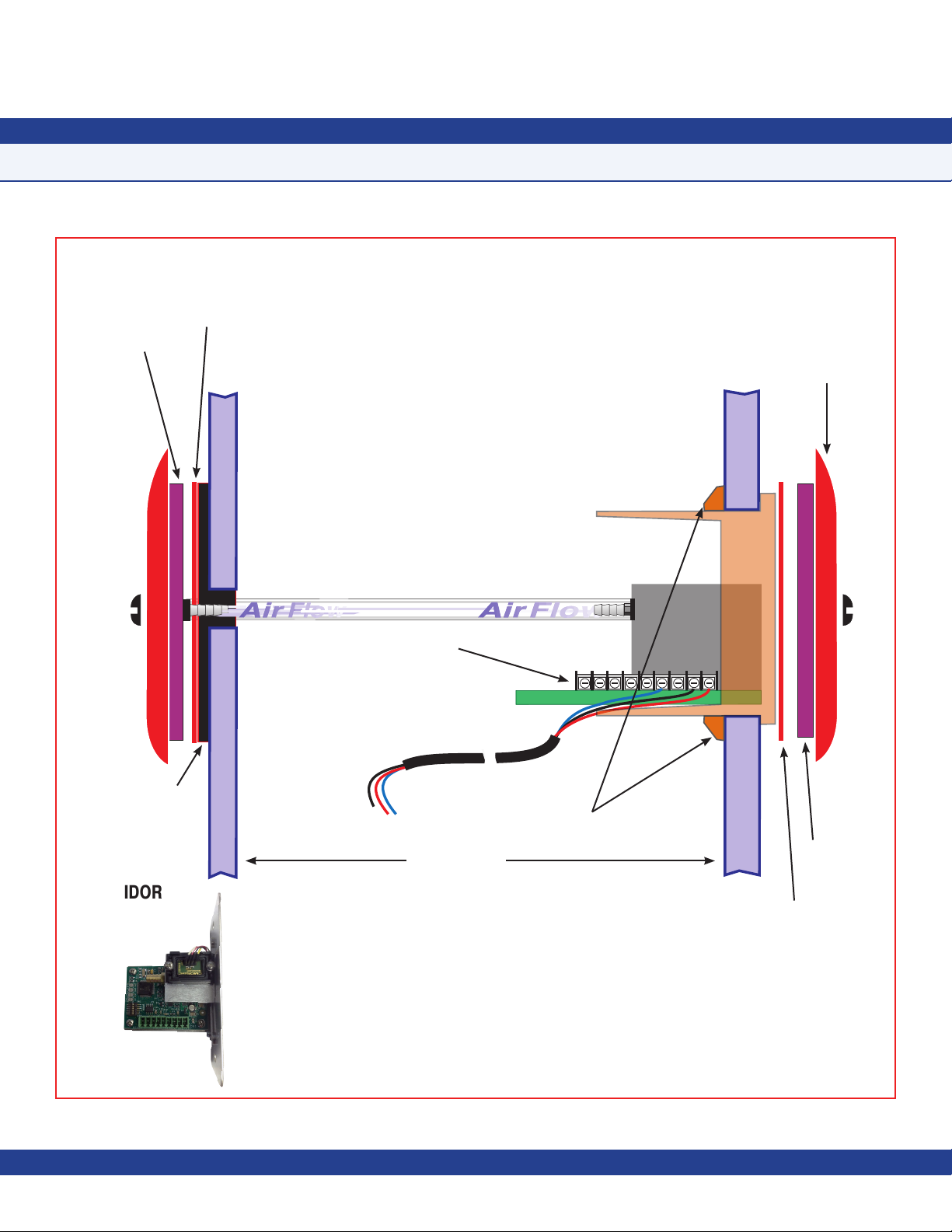
MOUNTING/WIRING
FMS-1655 with Standard Remote Sensor (9-Pin)
CORRIDOR
Gasket
Stainless Steel
Flow Tube
Mounting Plate
Wall Section
(cutaway view)
Flow Tube
When Flow Tube mounting plate
is located directly opposite the
sensor, flow tubing must be cut as
short as possible to prevent kinks.
For connection of
transmitter to FMS-1655.
Terminal
Stainless Steel
Mounting Plate
Gasket
Louvered Cover
Plate
ISOLATION
ROOM
NCNCGNDNCNCIoNC
GND
+Vin
Thin Silicone Caulking
(apply around tube and between
stainless steel plate and wall to seal
unit penetration)
~
~
Orange wall bracket
to be installed first
by using the rotating
clamps for secure
wall attachment.
Standard Remote Sensor Detail
(Side View)
- 10 -
To FMS-1655 Controller
Page 18
MOUNTING/WIRING
FMS-1655 with Standard Remote Sensor (9-Pin)
Stainless Steel
Flow Tube
Mounting Plate
ISOLATION
ROOM
Gasket
Thin Silicone Caulking
(apply around tube and
between stainless steel
plate and wall to seal unit
penetration)
Sensor installation requires the use of a three
conductor wire between the sensor and the main
controller module.
Flow Tube
When Flow Tube mounting plate is located
directly opposite the sensor, flow tubing must
be cut as short as possible to prevent kinks.
Terminal
For connection of
transmitter to
FMS-1655 .
To FMS-1655
Controller
Wall Section
(cutaway view)
~
~
NCNCGNDNCNCIoNC
Rotating clamps secure
assembly to wall board
GND
Louvered Cover
Plate
+Vin
Gasket
CORRIDOR
Stainless Steel
Mounting Plate
Standard Remote Sensor Detail
(Bottom View)
- 11 -
Page 19
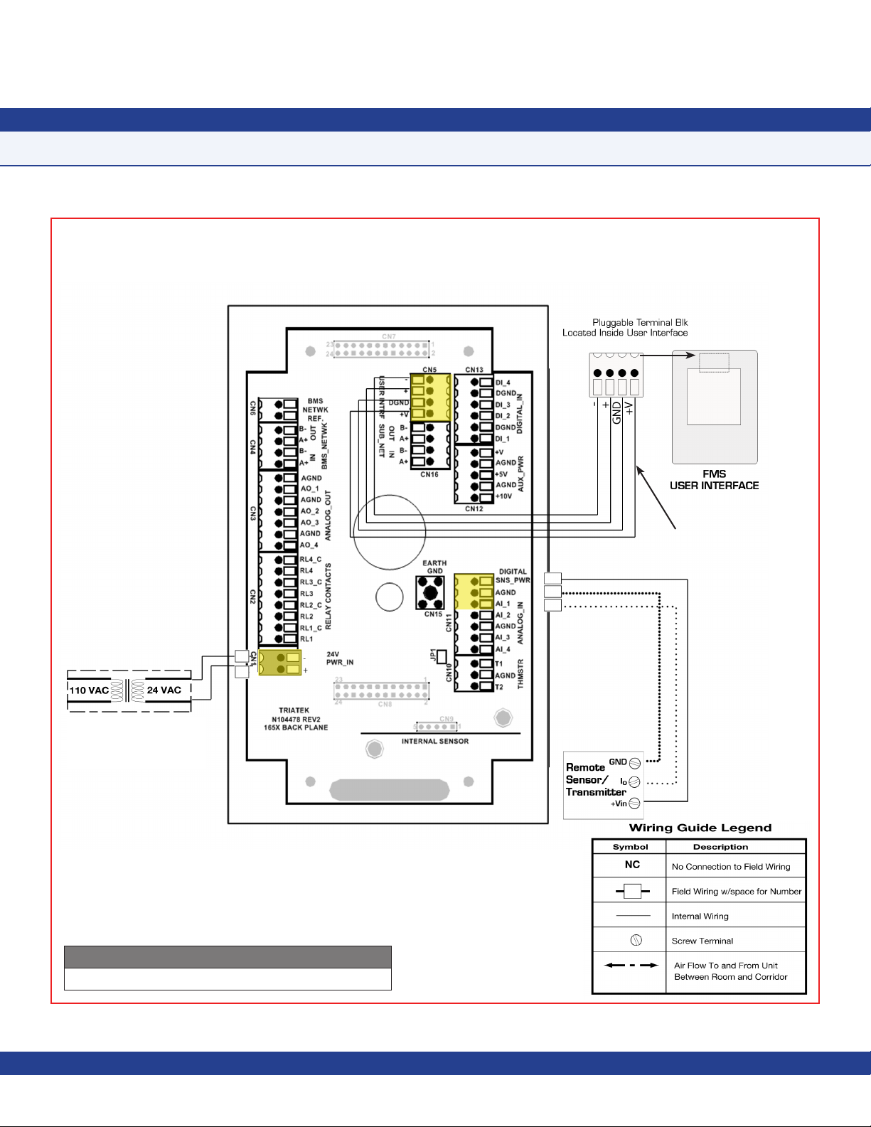
MOUNTING/WIRING
Remote Sensor Conguration
The electrical connections to the FMS-1655 made via a convenient backplate/backplate assembly is shown below. All wiring should conform
to the local regulations and National Electric Code. Take care not to run sensor wiring in the same conduit as the line voltage or other
conductors that supply highly inductive loads such as generators, motors, solenoids, contactors, etc. Use 22AWG or larger.
{
Recommended 4-conductor
connection: Belden 1325A
Step Down
Isolation Transformer
(provided with FMS Controller)
Controller Configuration Dipswitch Settings
S1 - 1 = ON, S1 - 5 = OFF (AI - 1 set at 4 - 20mA Input)
- 12 -
Page 20
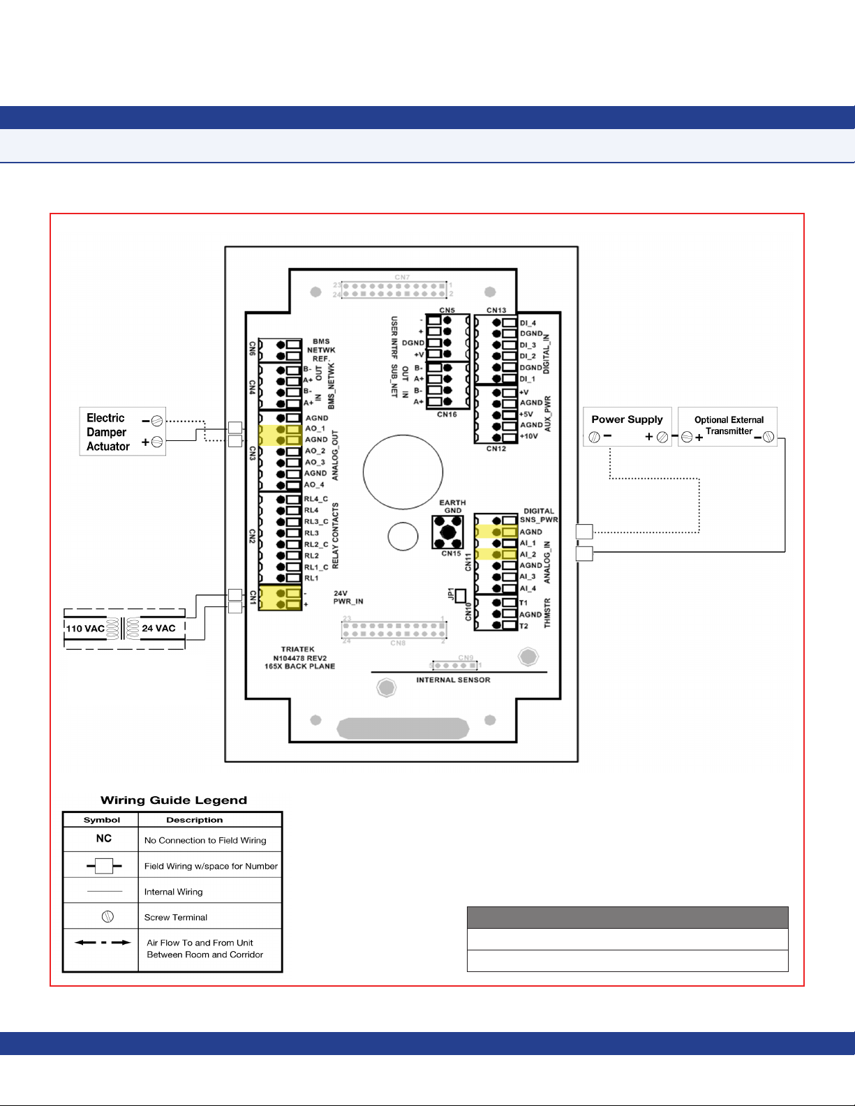
MOUNTING/WIRING - INTERNAL SENSOR
Analog Output to Electric Damper Actuator
Step Down
Isolation Transformer
(provided with FMS Controller)
Controller Configuration Dipswitch Settings
S1 - 2 = ON, S1 - 6 = OFF (AI - 2 set as 4 - 20mA Input)
S4 - 1 = ON (AO - 1 set as Voltage Output)
- 13 -
Page 21
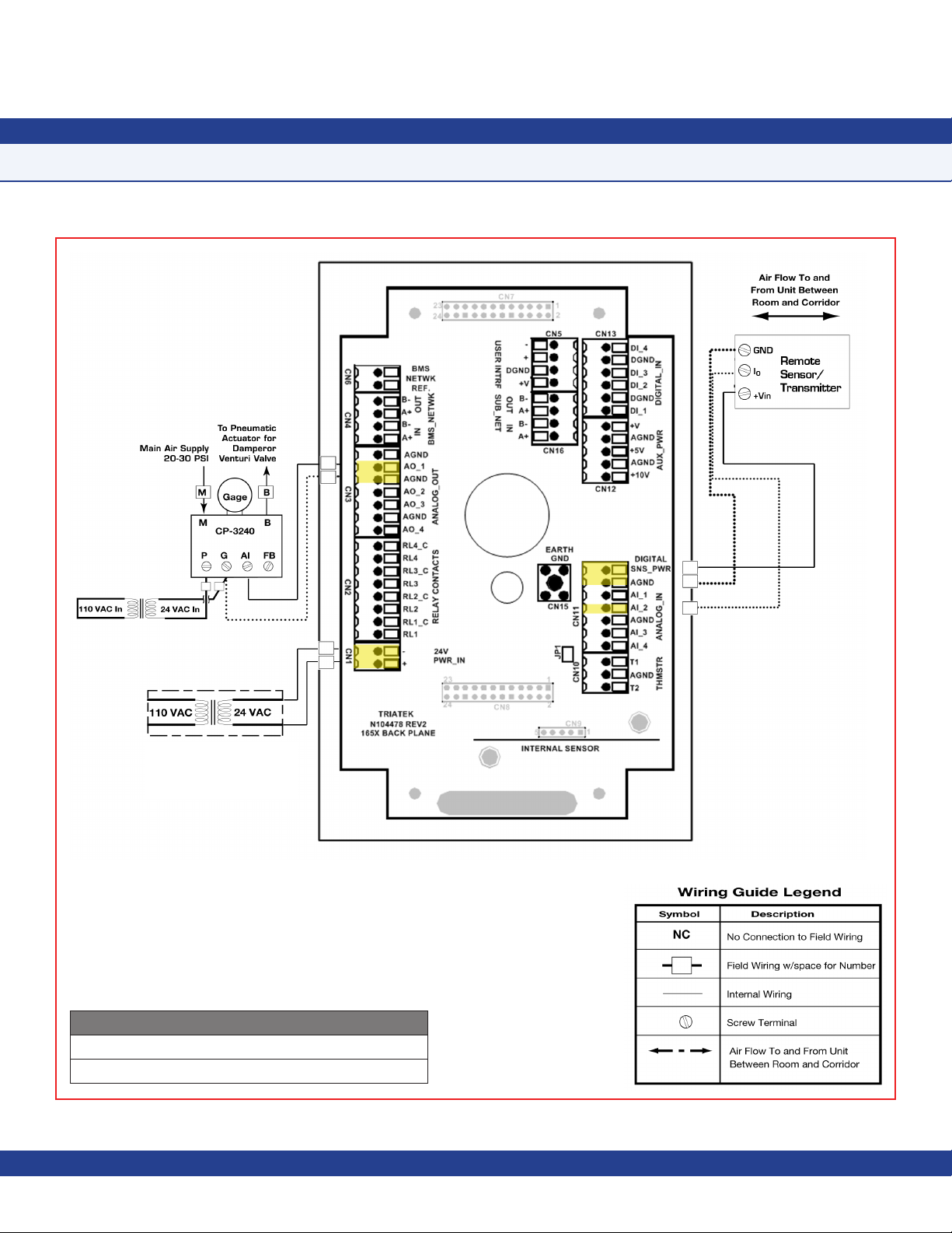
MOUNTING/WIRING - INTERNAL SENSOR
Analog Output to Pneumatic Damper Actuator
Optional remote sensor
Step Down
Isolation Transformer
(provided with FMS Controller)
Controller Configuration Dipswitch Settings
S1 - 2 = ON, S1 - 6 = OFF (AI - 2 set as 4 - 20mA Input)
S4 - 1 = ON (AO - 1 set as Voltage Output)
Due to continuous improvement, TRIATEK reserves the right to change product specifications without notice.
- 14 -
Page 22

MOUNTING/WIRING - INTERNAL SENSOR
Analog Output to Variable Speed Drive
Optional remote sensor
Step Down
Isolation Transformer
(provided with FMS Controller)
Controller Configuration Dipswitch Settings
S1 - 2 = ON, S1 - 6 = OFF (AI - 2 set as 4 - 20mA Input)
S4 - 1 = ON (AO - 1 set as Voltage Output)
- 15 -
Page 23

MOUNTING/WIRING - INTERNAL SENSOR
Analog Output to Modulated Air Controller
Optional remote sensor
Step Down
Isolation Transformer
(provided with FMS Controller)
Controller Configuration Dipswitch Settings
S1 - 2 = ON, S1 - 6 = OFF (AI - 2 set as 4 - 20mA Input)
S1 - 4 = ON, S1 - 8 = OFF (AI - 4 set as 4 - 20mA Input
Due to continuous improvement, TRIATEK reserves the right to change product specifications without notice.
- 16 -
Page 24

MOUNTING/WIRING - REMOTE SENSOR
Analog Output to Pneumatic Damper Actuator
Step Down
Isolation Transformer
(provided with FMS Controller)
Controller Configuration Dipswitch Settings
S1 - 1 = ON, S1 - 5 = OFF (AI - 1 set as 20mA Input)
S4 - 1 = ON (AO - 1 set as Voltage Output)
- 17 -
Page 25

MOUNTING/WIRING - REMOTE SENSOR
Analog Output to Variable Speed Drive
Step Down
Isolation Transformer
(provided with FMS Controller)
Controller Configuration Dipswitch Settings
S1 - 1 = ON, S1 - 5 = OFF (AI - 1 set as 20mA Input)
S4 - 1 = ON (AO - 1 set as Voltage Output)
Due to continuous improvement, TRIATEK reserves the right to change product specifications without notice.
- 18 -
Page 26
MOUNTING/WIRING
Adding Remote Pressure Sensor with 4-20mA Out to Internal Sensor Model
Step Down
Isolation Transformer
(provided with FMS Controller)
Controller Configuration Dipswitch Settings
S1 - 2 = ON, S1 - 6 = OFF (AI - 2 set as 4 - 20mA Input)
- 19 -
Page 27

MOUNTING/WIRING
Notes
- 20 -
Due to continuous improvement, TRIATEK reserves the right to change product specifications without notice.
Page 28

MOUNTING/WIRING
Analog Input to 2 Remote Pressure Sensors 4-20mA Out
Step Down
Isolation Transformer
(provided with FMS Controller)
Controller Configuration Dipswitch Settings
S1 - 1 = ON, S1 - 5 = OFF (AI - 1 set as 4 - 20mA Input)
S1 - 2 = ON, S1 - 6 = OFF (AI - 2 set as 4 - 20mA Input)
- 21 -
Page 29

MOUNTING/WIRING
Analog Input to 3 Remote Pressure Sensors 4-20mA Out
Step Down
Isolation Transformer
(provided with FMS Controller)
Controller Configuration Dipswitch Settings
S1 - 1 = ON, S1 - 5 = OFF (AI - 1 set as 4 - 20mA Input)
S1 - 2 = ON, S1 - 6 = OFF (AI - 2 set as 4 - 20mA Input)
S1 - 3 = ON, S1 - 7 = OFF (AI - 3 set as 4 - 20 mA Input)
Due to continuous improvement, TRIATEK reserves the right to change product specifications without notice.
- 22 -
Page 30

MOUNTING/WIRING
Analog Input to 4 Remote Pressure Sensors 4-20mA Out
Step Down
Isolation Transformer
(provided with FMS Controller)
Controller Configuration Dipswitch Settings
S1 - 1 = ON, S1 - 5 = OFF (AI - 1 set as 4 - 20mA Input)
S1 - 2 = ON, S1 - 6 = OFF (AI - 2 set as 4 - 20mA Input)
S1 - 3 = ON, S1 - 7 = OFF (AI - 3 set as 4 - 20 mA Input)
S1 - 4 = ON, S1 - 8 = OFF (AI - 4 set as 4 - 20 mA Input)
- 23 -
Page 31

MOUNTING/WIRING
Analog Input to Temperature Sensor
**
*
Step Down
Isolation Transformer
(provided with FMS Controller)
* The above example associates the Thermistor with contacts T1
and AGND for illustrative purposes only. In fact, either of the two
T#s can be used.
Due to continuous improvement, TRIATEK reserves the right to change product specifications without notice.
- 24 -
Page 32
MOUNTING/WIRING
Analog Input to Custom Remote Sensor
Step Down
Isolation Transformer
(provided with FMS Controller)
Controller Configuration Dipswitch Settings
S1 - 2 = OFF, S1 - 6 = ON (AI - 2 set as 0 - 10V Input)
- 25 -
Page 33

MOUNTING/WIRING
Digital Input to Door Switch
A switch having normally-open or normally close contacts may be used with the FMS-1655 to serve as a timed alarm buzzer inhibit, when the
room door has been opened. An optional door switch may be purchased from JCI for this specific purpose.
After the switch has been installed at the door and connected to the FMS unit, its operation may be programmed as described on page 39.
Step Down
Isolation Transformer
(provided with FMS Controller)
Due to continuous improvement, TRIATEK reserves the right to change product specifications without notice.
Controller Configuration Slideswitch Settings
S5 = Left (Active - Low Digital Input)
- 26 -
Page 34

MOUNTING/WIRING
SUBHEAD
Notes
- 27 -
Page 35

MOUNTING/WIRING
Digital Input to Occupancy Sensor
Step Down
Isolation Transformer
(provided with FMS Controller)
* The above example associates the Occupancy Sensor with
contacts DI4 and DGND for illustrative purposes only. In fact, any
of the four DI#s can be used.
Controller Configuration Slideswitch Settings
S5 = Left (Active - Low Digital Input)
- 28 -
Page 36

MOUNTING/WIRING
SUBHEAD
Relay Output to Alarm
*
Step Down
Isolation Transformer
(provided with FMS Controller)
* The above example associates Monitor Output 1 with contacts
RL3 and RL3_C for illustrative purposes only. In fact, any of the
four RL#s (and the corresponding RL#_C) can be used.
- 29 -
Page 37

MOUNTING/WIRING
Relay Output to Warning
Step Down
Isolation Transformer
(provided with FMS Controller)
* The above example associates Monitor Output 2 with contacts
RL3 and RL3_C for illustrative purposes only. In fact, any of the
four RL#s (and the corresponding RL#_C) can be used.
- 30 -
Page 38
MOUNTING/WIRING
SUBHEAD
Relay Output 1
Step Down
Isolation Transformer
(provided with FMS Controller)
* The above example associates Heating State 1 with contacts
RL1 and RL1_C for illustrative purposes only. In fact, any of the
four RL#s (and the corresponding RL#_C) can be used.
- 31 -
Page 39

MOUNTING/WIRING
Relay Output 2
Step Down
Isolation Transformer
(provided with FMS Controller)
* The above example associates Heating State 2 with contacts
RL2 and RL2_C for illustrative purposes only. In fact, any of the
four RL#s (and the corresponding RL#_C) can be used.
- 32 -
Page 40

MOUNTING/WIRING
SUBHEAD
Power
Step Down
Isolation Transformer
(provided with FMS Controller)
- 33 -
Page 41

Red / 24 VAC / 30VA
connected to the FMS
}
Only Class 2 wiring in
this compartment.
MOUNTING/WIRING
Isolated Power Supply
Transformer
50/60 Hz
Ground
Blue
240 VAC
50/60 Hz
120 VAC
50/60 Hz
White
*
Note:
This product should be installed with the manufacturer provided isolated power supply and connected to an electrical
circuit protected by a minimum 20A circuit breaker. This circuit breaker should be mounted in an approved electrical
enclosure located separately, but in close proximity to this product.
}
}
Black
Stepdown Isolation Transformer
(provided with FMS-1655)
1 Amp Slow
Blow Fuse
- 34 -
Page 42

MOUNTING/WIRING
SUBHEAD
Notes
- 35 -
Page 43

COMMUNICATIONS - BACnet® MS/TP
Wiring
NOTE: For optimum network communications, the reference signal (REF)
must be connected to the "BMS NETWK REF" terminals at the backplane.
To minimize offline conditions on Metasys trunks resulting from delayed
responses from the BACnet controller, the NETWORK TOLERANCE
parameter in Metasys should be set to HIGH.
Controller Configuration Dipswitch Settings
S3 - 7 = ON, S3 - 8 = ON (BACnet MS/TP protocol selected)
- 36 -
Page 44
COMMUNICATIONS - Metasys® N2 Open
SUBHEAD
Wiring
NOTE: For optimum network communications, the reference
signal (REF) must be connected to the "NETWK REF"
terminals at the backplane.
Controller Configuration Dipswitch Settings
S3 - 7 = ON, S3 - 8 = OFF (Metasys N2 Open protocol selected)
- 37 -
Page 45

QUICK START GUIDE
FMS-1655 Quick Start Guide
Introduction
Following the proper installation of the
FMS-1655, apply power to the unit and
confirm that you hear a brief chirp at the
touchscreen display, which indicates that
the display module is communicating with
the controller module. Upon power up, the
Safety Halo
TM
status indication bezel will
cycle through seven colors (red, green, blue,
yellow, magenta, cyan, and white) followed by
three action icons (normal, caution, alarm),
and finally the JCI splash screen will remain
displayed for approximately 10 seconds and
will then disappear to reveal the main display
screen.
NOTE: The information displayed on the
splash screen during the power up sequence
may also be redisplayed using the About This
FMS option on the Diagnostics menu.
Each FMS-1655
comes preconfigured in
neutral isolation
mode.
Main Display Screen
All FMS-1655 units are shipped from the
factory in the neutral isolation mode, which
is represented by a blue graphical screen
with a slashed circle status icon at the center
of the screen as shown in the figure above.
The information that is displayed on the main
screen includes the following from top to
bottom:
• Isolation room name in the upper window
(up to 24 characters)
• Current differential pressure (default units:
in WC)
• Current status and isolation mode
• Status icon centrally located
• Current temperature in the lower window (if
so equipped)
• Current humidity in the lower window (if so
equipped)
• Current time and date in the lower window
Located just below the lower window with the
time and date display is the audible toggle
button, which may be used to temporarily
silence the audible alarm in the event of an
alarm condition.
While in neutral isolation mode, the graphical
background is blue in color. While in either
positive or negative isolation, the graphical
background intuitively represents the current
alarm status of the unit.
A green graphical background with a
checkmark at the center indicates that the
current differential pressure is within allowable
limits of the desired setpoint. A yellow
graphical background with an exclamation
point at the center indicates one of two
conditions: 1) door to the monitored space
is open (if door switch is enabled), or 2)
the current differential pressure has drifted
outside the allowable limits of the desired
setpoint and is in the caution range. A red
graphical background with an exclamation
point at the center indicates that the current
differential pressure has reached a critical
unsafe condition, as it is beyond the safe
operating range. An alarm buzzer will sound
at this screen as well providing an audible
alert of the unsafe conditions.
The FMS-1655 incorporates a full-color
touchscreen and includes an extensive easyto-use menu system that allows the user to
quickly setup the controller for immediate use.
Also integrated into the FMS-1655 display are
several hotspots that provide quick access to
various settings. Refer to page 51 for details
on using these hotspots as display settings
shortcuts. Touching the screen anywhere
other than one of the reserved hotspots
invokes the menu system, unless one or more
security passwords have been entered.
Automated Clean Cycle
If this FMS-1655 is controlling the differential
pressure of the monitored space, there
is a convenient feature that allows quick
turnover of the room referred to as auto clean
cycle mode. When a patient who has been
occupying an isolation room or patient room
is removed, the room must be purged of all
airborne contaminants in preparation for the
next patient. The auto clean cycle feature
of the FMS-1655 automates this cleaning
process and is fully programmable. This
feature may be activated from either the
isolation mode hotspot on the main display
screen, or via the isolation mode option on the
Room Setup Menu.
Clean Cycle
Mode in
operation
displaying time
remaining for
cycle completion.
- 38 -
Page 46

SUBHEAD
QUICK START GUIDE
FMS-1655 Quick Start Guide
When activated, Auto Clean Cycle opens
the exhaust valve or damper to its maximum
position to purge the room of any airborne
contaminants. The exhaust valve or damper
will remain in the maximum position for a
programmable period of time while the room
is being cleaned. The clean cycle duration
may be configured for a minimum of 10
minutes up to 4 hours in increments of one
minute. While the Auto Clean Cycle is in
progress, a countdown timer indicates the
time remaining for the process, and the Safety
HaloTM will flash slowly in cyan to indicate
that the monitored space is being cleaned.
When the Auto Clean Cycle is completed, a
message will appear on the screen indicating
that the room has been successfully cleaned.
This message will remain on the screen
until it has been acknowledged by a user, at
which time it returns the unit to the previously
selected isolation mode.
An active Auto Clean Cycle may be canceled
by touching the countdown timer in the upper
LCD window. A message will be displayed
warning the user that aborting the cleaning
process may result in insufficient cleaning
of the monitored room. Touching the main
display screen anywhere other than the upper
LCD window will result in a warning beep
with no menu access. If at least one security
password has been stored in the system,
touching the screen to abort the Auto Clean
Cycle that is in progress will request a valid
password before aborting the mode.
Configuring Room Pressure Monitor
Configuring the FMS-1655 isolation room
controller settings can be accomplished in
four (4) simple steps:
1. Configure analog output
2. Configure door switch
3. Configure alarm relay output
4. Configure alarm limits
The FMS-1655 comes pre-configured with
either an internal sensor or remote sensor,
depending on the specific model ordered. The
flush-mount models incorporate an internal
differential pressure sensor, while the surfacemount models include a separately installed
remote differential pressure sensor. In either
case, the next step would be to configure
the analog output that controls the damper
actuator in the monitored room, if control
is required. If the application only requires
monitoring, then this step may be omitted.
Setting Up Analog Output
For those applications requiring control of a
damper actuator, the analog output must be
configured accordingly. Select Unit Setup
> Controller Setup > Analog Output and
the user is prompted to select an operating
mode (direct control or PID control) and an
operating range. Most applications will take
advantage of the PID (proportional-integralderivative) control mode, where the control
output can be customized by varying the
control loop constants. The operating range
can either include an offset from zero or not,
independent of whether the analog output is
configured for current or voltage mode.
Once the operating mode and range are
selected, the user is prompted to specify the
upper and lower limits of the analog output as
percentages. Most applications will use the
default settings of zero and 100 percent. But
for those applications where the top or bottom
limits need to be tweaked, these settings may
be adjusted accordingly to further limit the
range of the actual analog output signal.
Finally, the user is prompted to enter the
target setpoint for the current mode of
isolation. This setpoint will be used by the
FMS-1655 to dither the analog output in
order to achieve the desired target differential
pressure. The analog output can be
configured for either direct acting or reverse
acting mode. Each mode of isolation has its
own setpoint and operating mode. Therefore,
switching from positive isolation to negative
isolation can automatically affect both the
target setpoint as well as the acting mode for
the analog output.
To confirm that the analog output is properly
configured for the specific installation at hand,
use the Overrides option on the Diagnostics
menu to manually override analog output
1 which is controlling the exhaust damper
actuator. Moving the slider from zero to
100 percent should cause the damper to
move from closed to full open, or vice versa,
depending upon the acting mode of the
actuator.
Enabling Door Switch
To prevent the FMS-1655’s control output
from ramping up or down unnecessarily when
the door of the monitored space is opened,
a door switch may be configured to suspend
the operation of the PID control output.
This effectively “freezes” the analog output
controlling the exhaust or supply damper until
the door closes. The option for configuring the
door switch can be found on the Controller
Setup menu under the Unit Setup menu. A
delay time of up to 60 minutes (in one-second
increments) may be associated with the door
switch, which effectively delays the return
to normal PID control output mode while
the monitored space resumes its positive
or negative differential pressure. If the door
switch option is enabled, the main display will
- 39 -
Page 47

QUICK START GUIDE
FMS-1655 Quick Start Guide
revert to the yellow graphical caution screen
whenever the door is open and the unit is
not in neutral isolation mode. Once the door
closes, the door delay will count down, and
then release the suspended control output
once it expires.
Setting Up Alarm Relay Output
When the alarm status must be transmitted to
a remote location, like a nurses’ station, the
alarm relay output can be configured using
the following procedure. Select Unit Setup
> Controller Setup > Relay Setup and the
user is prompted to select the trigger mode
(setpoints, isolation mode, or occupancy
mode). The default trigger mode is Setpoints,
which allows the alarm relay to be activated
based on exceeding setpoint limits entered
by the user. Isolation Mode and Occupancy
Mode allow the alarm relay to be activated
based on a change in the mode of isolation
and state of occupancy, respectively. Once
the relay trigger mode is selected, the user
is prompted to enter the high and low relay
setpoints using the sliders on the popup
screen. Finally, the operating mode (direct or
reverse acting) must be specified along with
a delay time. The delay time determines how
long the alarm relay output is delayed before
being activated after one of the relay setpoint
limits has been exceeded. The default setting
for the delay time is zero seconds.
Setting Alarm Limits
To determine the limits at which the unit status
changes from normal to warning, and from
warning to alarm, the alarm limits must be
configured as follows. Select Unit Setup >
Controller Setup > Alarm Limits and the user
is prompted to specify the high and low alarm
and warning limits. These limits should be
specified to set the differential pressure range
which is considered normal, as well as the
range which indicates a warning condition,
and the range which is considered critical and
indicates an alarm condition.
Changing Isolation Mode
The FMS-1655 isolation room controller
may be configured for Positive, Negative, or
Neutral modes of isolation. To change the
mode of isolation, select Unit Setup > Room
Setup > Isolation Mode and select one of
three isolation modes, or Auto Clean mode.
Auto Clean mode automates the turnover of
an isolation room that has been vacated in
preparation for the next occupant. For those
states or locales that have code restrictions
regarding the accessible modes of isolation,
the unit may be configured to allow either
Positive and Neutral or Negative and Neutral
modes. Changing the mode of isolation
automatically selects the pre-programmed
setpoints and alarm limits associated with
each mode.
Invoking Auto Clean Cycle
When an isolation room has been vacated, it
must be cleaned of all airborne contaminants
before the next patient may occupy the room.
The FMS-1655 includes a convenient feature
called Auto Clean Cycle that automates the
turnover process and cleaning of the room.
Auto Clean Cycle may be invoked using
one of two methods, either from the Status
hotspot on the main display screen or from
the Isolation Mode option on the Isolation
Room Setup menu. Invoking Auto Clean
Cycle automatically commands the exhaust
valve or damper for maximum flow for the
configured duration to facilitate the removal of
all airborne contaminants. If the Safety HaloTM
status bezel has been enabled, it will flash
in cyan color to indicate that an Auto Clean
Cycle is in progress. When the Auto Clean
Cycle is completed, a message will appear
on the main display screen indicating that the
monitored room was successfully cleaned
and is available for use. The Safety HaloTM
will stop flashing but remain cyan until this
message is acknowledged by the user.
Changing Network Settings
Changing network settings on the FMS-1655
can be accessed by selecting Unit Setup >
Network Setup. Depending upon the protocol
selected, the Network Setup menu will
present the user with the available options. All
FMS-1655 demo units have a default protocol
selection of BACnet, and therefore the
Network Setup menu options pertain to this
protocol. From this menu, the user can select
a different baud rate or change the network
address of the unit.
Adding Password Security
The FMS-1655 menu system can be
protected by adding up to ten (10) multi-level
passwords to the system. A password entry
may be created by selecting System Setup
> Next > Passwords Setup > Add Password
and the user is prompted to enter a minimum
of four (4) and up to eight (8) digits. Once
a password has been specified, the user is
prompted to specify one of four access levels:
Unrestricted, Standard, Basic, and Restricted.
All password entries are saved to non-volatile
memory. If a password is forgotten, there is a
factory-default “back door” password that will
provide unrestricted access to the user menu
system. Please consult with the factory for
more information regarding this password.
Note: The first user password is
automatically saved as unrestricted.
Changing Display Settings
The Safety Halo™ feature is exclusive to
- 40 -
Page 48

QUICK START GUIDE
FMS-1655 Quick Start Guide
the 1655 series of controllers from JCI, and
significantly enhances the visibility of the
status of individual units installed along a
long corridor or hallway, and allows an unsafe
condition to be immediately recognized. The
display settings of this enhanced feature
may be configured using the Safety Halo™
option on the Display Setup menu. This
option may be disabled if not required by
the installation, which simply turns off the
Safety Halo™ status indicator. If enabled, the
brightness may be adjusted from full intensity
down to barely visible in daylight conditions.
For convenience, the Safety Halo™ status
indicator incorporates a Nightly Auto-Dim
feature which allows the brightness of the
status indicator to automatically reduce in
intensity at a designated hour every day, and
then resume normal brightness at another
designated hour. The brightness of the
FMS-1655 main display screen may also
be adjusted using the Set Brightness option
on the Display Setup menu. All brightness
settings are stored to non-volatile memory
and remain in effect through a power cycle.
The Display Modes menu option on the
Display Setup menu allows users to select
a display mode based on the number of
pressure sensors being monitored. The
display mode is pre-configured at the factory
based on the sensor count, but may be
changed after adding or removing a sensor.
The main display screen of the FMS-1655
may be customized by using the Display
Setup menus. The Display Options menu
option allows specific information to be
individually suppressed by deselecting the
unwanted items from the Set Display Options
selection screen. Changing the time and
date can be accomplished either by using
the hotspots on the main display screen, or
by selecting the Set Time & Date option. The
time and date settings are volatile and are not
saved to non-volatile memory on demo units.
However, an operational unit connected to a
controller module can retain its time and date
settings for up to two hours in the event of a
power failure.
Built-in Diagnostics
The FMS-1655 incorporates several
useful diagnostic tools that may aid in
troubleshooting the system during the
installation and commissioning phase. The
Overrides option allows both analog and
relay outputs to be overridden individually.
Each analog output may be locked at the
overridden percentage while test and balance
makes adjustments to supply or exhaust
dampers, for example. While in the overridden
state, the analog output is “disconnected”
from its PID control loop, if enabled.
Cancelling the override effectively resumes
the normal PID control loop operation, again
if enabled.
A unique feature of the FMS-1655 is the Real-
Time View option, which allows the user to
see in real-time the actual inputs and outputs,
along with their voltage levels or states. One
of the most useful tools for fine-tuning the
PID loop performance is the Analog I/O Pairs
screen, which displays the analog input and
its current setpoint, along with the analog
output which is mapped to it. This allows the
user to see in real-time the varying analog
input signal and its corresponding analog
output control signal.
To preserve the configuration settings
after verifying that everything is configured
properly, the Save Settings option on the
Diagnostics menu will take a snapshot of
the current configuration settings for later
retrieval. In the event that any configuration
settings are inadvertently overwritten, they
may be restored either to the previously saved
user settings or to the factory-default settings.
To help maintain the long-term accuracy of
the FMS-1655 differential pressure reading, a
zero calibration feature has been incorporated
which allows the user to zero the display after
allowing the differential pressure between the
monitored room and the reference space to
neutralize, e.g., door open. Once the pressure
has stabilized, performing a zero calibration
ensures that the display reading accurately
shows that the pressure has equalized while
the door to the monitored space is left open.
Volumetric Offset Control
The FMS-1655 includes the ability to control
the supply and general exhaust air flow
devices in a laboratory application with
multiple fume hoods. This requires the use of
JCI’s Universal Valve Module to bring the total
supply and exhaust flows into the FMS-1655.
To configure the FMS-1655 for volumetric
offset control, simply configure AI-3 as the
supply flow input, and AI-4 as the exhaust
flow input. The volumetric offset setpoint must
be entered while configuring AI-4. Be sure to
select Vol. Offset Control on the Flow Sensor
Input configuration screen. The volumetric
offset control signal is output on AO-4, which
may be daisy-chained to each of the supply
air flow devices. The secondary temperature
control signal for heating is output on AO-2,
which may be daisy-chained to each of the
reheat valves. For more information on using
the FMS-1655 for volumetric offset control
applications, please refer to the FMS-1655
Programmer’s Guide.
- 41 -
Page 49

QUICK START GUIDE
Notes
- 42 -
Due to continuous improvement, TRIATEK reserves the right to change product specifications without notice.
Page 50

SUBHEAD
MODULE SETTINGS
Conguring Display Module Settings
Options Dipswitch (S1) – internal use only
1. Graphics Chip Mode Selection OFF = Programming Mode ON = Run Mode
2. Touch Screen Calibration Mode OFF = Force calibration ON = Auto calibration
3. Reserved
4. Reserved
Options Dipswitch (S2) – mode configuration 1
1. Product Type OFF = FMS/HMS ON = CMS-1655
2. Remote Display OFF = Disabled ON = Enabled
3. Mode Select OFF = FMS-1655 / CMS-1655 ON = HMS-1655
4. Operational Mode: OFF = Demo Mode ON = Run Mode
Pushbutton Switch (SW1): Reset Button
Pushbutton Switch (SW2): Reserved
- 43 -
Page 51

MODULE SETTINGS
Conguring Main Controller Module Settings
Analog Input Configuration Dipswitch (S1)
1. AI-1 Mode Selection: OFF = voltage input ON = current input
2. AI-2 Mode Selection: OFF = voltage input ON = current input
3. AI-3 Mode Selection: OFF = voltage input ON = current input
4. AI-4 Mode Selection: OFF = voltage input ON = current input
5. AI-1 Voltage Range Selection: OFF = 0-5Vdc ON = 0-10Vdc
6. AI-2 Voltage Range Selection: OFF = 0-5Vdc ON = 0-10Vdc
7. AI-3 Voltage Range Selection: OFF = 0-5Vdc ON = 0-10Vdc
8. AI-4 Voltage Range Selection: OFF = 0-5Vdc ON = 0-10Vdc
NOTES: To configure FMS-1655 for an internal sensor, set dipswitch position 1 to OFF and dipswitch position 5 to OFF. To configure
FMS-1655 for a remote sensor, set dipswitch position 1 to ON and dipswitch position 5 to OFF. For other inputs, see Table 1.
Analog Output Configuration Dipswitch (S3)
1. AO-1 Mode Selection: OFF = current output ON = voltage output
2. AO-2 Mode Selection: OFF = current output ON = voltage output
3. AO-3 Mode Selection: OFF = current output ON = voltage output
4. AO-4 Mode Selection: OFF = current output ON = voltage output
Network Configuration Dipswitch (S3)
5. RS485 Network Termination: OFF = disabled ON = enabled
6. RS485 Display Termination: OFF = disabled ON = enabled
7. Protocol Select: see Table 2 below
8. Protocol Select: see Table 2 below
- 44 -
Page 52

SUBHEAD
MODULE SETTINGS
Congurations & Settings
Table 1. Analog Input Configuration Settings (S1)
Mode S1 - 1 S1 - 2 S1 - 3 S1 - 4 S1 - 5 S1 - 6 S1 - 7 S1 - 8
AI-1 5Vdc OFF OFF
AI-1 20mA ON OFF
AI-1 10Vdc OFF ON
Not Valid ON ON
AI-2 5Vdc OFF OFF
AI-2 20mA ON OFF
AI-2 10Vdc OFF ON
Not Valid ON ON
AI-3 5Vdc OFF OFF
AI-3 20mA ON OFF
AI-3 10Vdc OFF ON
Not Valid ON ON
AI-4 5Vdc OFF OFF
AI-4 20mA ON OFF
AI-4 10Vdc OFF ON
Not Valid ON ON
Table 2. Protocol Selection Settings (S3)
Protocol Selection S3-7 S3-8
Reserved OFF OFF
Metasys® N2 ON OFF
BACnet® MS/TP (default) ON ON
Controller Configuration Dipswitch (S4)
1. AO-1 Voltage Range Selection: OFF = 0-10Vdc ON = 0 - 5Vdc
2. AO-2 Voltage Range Selection: OFF = 0-10Vdc ON = 0 - 5Vdc
3. AO-3 Voltage Range Selection: OFF = 0-10Vdc ON = 0 - 5 Vdc
4. AO-4 Voltage Range Selection: OFF = 0-10Vdc ON = 0 - 5 Vdc
Controller Configuration Slideswitch (S5):
LEFT = Digital Inputs pulled-high (triggered by active low input - default)
RIGHT = Digital Inputs pulled-low (triggered by active high input, up to 24Vdc)
- 45 -
Page 53

BACnet® OBJECTS
BACnet® Objects
The following table itemizes the list of points available for integration in a building management system (BMS). This table contains the objects
for open BACnet integration.
Object Read
Analog Inputs
AI - 1 Analog Input 1 (default: Isolation Pressure) Read-Only
AI - 2 Analog Input 2 Read-Only
AI - 3 Analog Input 3 Read-Only
AI - 4 Analog Input 4 Read-Only
AI - 5 Thermistor Input 1 Read-Only
AI - 6 Thermistor Input 2 Read-Only
Analog Outputs
AO - 1 Analog Output 1 (default: Damper Position) Read-Only
AO - 2 Analog Output 2 (default: Anteroom Damper Control) Read-Only
AO - 3 Analog Output 3 (spare control output) Read-Only
AO - 4 Analog Output 4 (spare control output) Read-Only
Binary Inputs
BI - 1 Digital Input 1 (default: Door Switch) Read-Only
BI - 2 Digital Input 2 (default: Anteroom Door Switch) Read-Only
BI - 3 Digital Input 3 (spare digital input) Read-Only
Analog Values (continued)
AV - 5 TI-1 Setpoint Read/Write
AV - 6 TI-2 Setpoint Read/Write
AV - 7 Air Change Rate based on Flow Input at AI-1 Read/Write
AV - 8 Air Change Rate based on Flow Input at AI-2 Read/Write
AV - 9 Air Change Rate based on Flow Input at AI-3 Read/Write
AV - 10 Air Change Rate based on Flow Input at AI-4 Read/Write
AV - 11 Alarm Relay 1 High Setpoint Read/Write
AV - 12 Alarm Relay 1 Low Setpoint Read/Write
AV - 13 Alarm Relay 2 High Setpoint Read/Write
AV - 14 Alarm Relay 2 Low Setpoint Read/Write
AV - 15 Alarm Relay 3 High Setpoint Read/Write
AV - 16 Alarm Relay 3 Low Setpoint Read/Write
AV - 17 Not user-selectable Read/Write
AV - 18 Not user-selectable Read/Write
AV - 19 AI-1 Low Alarm Setpoint (low pressure alarm) Read/Write
AV - 20 AI-1 Low Warning Setpoint (low pressure warning) Read/Write
BI - 4 Digital Input 4 (spare digital input) Read-Only
Binary Outputs
BO - 1 Relay Output 1 (default: Primary Alarm Relay Output) Read-Only
BO - 2 Relay Output 2 (default: Spare Relay Output) Read-Only
BO - 3 Relay Output 3 (spare relay output) Read-Only
BO - 4 Not user-selectable Read-Only
Analog Values
AV - 1 AI-1 Setpoint (Room Pressure) Read/Write
AV - 2 AI-2 Setpoint Read/Write
AV - 3 AI-3 Setpoint Read/Write
AV - 4 AI-4 Setpoint Read/Write
AV - 21 AI-1 High Warning Setpoint (high pressure warning) Read/Write
AV - 22 AI-1 High Alarm Setpoint (high pressure alarm) Read/Write
AV - 23 AI-2 Low Alarm Setpoint Read/Write
AV - 24 AI-2 Low Warning Setpoint Read/Write
AV - 25 AI-2 High Warning Setpoint Read/Write
AV - 26 AI-2 High Alarm Setpoint Read/Write
AV - 27 AI-3 Low Alarm Setpoint Read/Write
AV - 28 AI-3 Low Warning Setpoint Read/Write
AV - 29 AI-3 High Warning Setpoint Read/Write
AV - 30 AI-3 High Alarm Setpoint Read/Write
AV - 31 AI-4 Low Alarm Setpoint Read/Write
- 46 -
Page 54

SUBHEAD
BACnet® OBJECTS
BACnet® Objects
Object Read
Analog Values (continued)
AV - 32 AI-4 Low Warning Setpoint Read/Write
AV - 33 AI-4 High Warning Setpoint Read/Write
AV - 34 AI-4 High Alarm Setpoint Read/Write
AV - 35 TI-1 Low Alarm Setpoint Read/Write
AV - 36 TI-1 Low Warning Setpoint Read/Write
AV - 37 TI-1 High Warning Setpoint Read/Write
AV - 38 TI-1 High Alarm Setpoint Read/Write
AV - 39 TI-2 Low Alarm Setpoint Read/Write
AV - 40 TI-2 Low Warning Setpoint Read/Write
AV - 41 TI-2 High Warning Setpoint Read/Write
AV - 42 TI-2 High Alarm Setpoint Read/Write
AV - 43 Writable Network Variable – Humidity Read/Write
AV - 44 Writable Network Variable – Temperature Read/Write
AV - 45 Writable Network Variable – Air Changes Read/Write
AV - 46 Writable Network Variable – Differential Pressure Read/Write
Analog Values (continued)
AV - 60 AI-3 Deadband Setting Read/Write
AV - 61 AI-4 Deadband Setting Read/Write
AV - 62 TI-1 Deadband Setting Read/Write
AV - 63 TI-2 Deadband Setting Read/Write
Multistate Objects
MSO - 1
MSO - 2
MSO - 3 Primary Alarm Status: 1=normal, 2=warning, 3=alarm Read-Only
MSO - 4 Secondary Alarm Status: 1=normal, 2=warning, 3=alarm Read-Only
MSO - 5 AI-3 Alarm Status: 1=normal, 2=warning, 3=alarm Read-Only
MSO - 6 AI-4 Alarm Status: 1=normal, 2=warning, 3=alarm Read-Only
MSO - 7 TI-1 Alarm Status: 1=normal, 2=warning, 3=alarm Read-Only
MSO - 8 TI-2 Alarm Status: 1=normal, 2=warning, 3=alarm Read-Only
MSO - 9 Offset Control Status Read-Only
Primary solation Mode: 1=positive, 2=negative, 3=neutral
Secondary Isolation Mode: 1=positive, 2=negative, 3=neutral
Read/Write
Read/Write
AV - 47 Device ID Offset (range: 0 – 4,194,000) Read/Write
AV - 48 Duct Air Flow based on AI-1 flow input Read-Only
AV - 49 Duct Air Flow based on AI-2 flow input Read-Only
AV - 50 Duct Air Flow based on AI-3 flow input (Supply Flow) Read-Only
AV - 51 Duct Air Flow based on AI-4 flow input (Exhaust Flow) Read-Only
AV - 52 Volumetric Offset (Supply Flow – Exhaust Flow) Read-Only
AV - 53 Volumetric Offset Setpoint Read-Write
AV - 54 AO-1 Override Level Read-Write
AV - 55 AO-2 Override Level Read-Write
AV - 56 AO-3 Override Level Read-Write
AV - 57 AO-4 Override Level Read-Write
AV - 58 AI-1 Deadband Setting Read/Write
AV - 59 AI-2 Deadband Setting Read/Write
JCI reserves the right to change product specifications without notice.
- 47 -
Page 55

METASYS® N2 OBJECTS
Metasys® N2 Objects
The following table itemizes the list of points available for integration in a building management system (BMS). This table contains the objects for
open N2 integration.
Object Functional Description Read or Write
Analog Inputs
AI - 1 Analog Input 1 (default: Primary Pressure) Read-Only
AI - 17 Analog Input 2 Read-Only
AI - 18 Analog Input 3 Read-Only
AI - 19 Analog Input 4 Read-Only
AI - 20 Thermistor Input 1 Read-Only
AI - 21 Thermistor Input 2 Read-Only
Analog Outputs
AO - 1 Analog Output 1 (default: Primary Damper Control) Read-Only
AO - 11 Analog Output 2 (default: Supply/Exhaust Damper Read-Only
AO - 12 Analog Output 3 (spare control output) Read-Only
AO - 13 Analog Output 4 (spare control output) Read-Only
Binary Inputs
BI - 3 Digital Input 1 (default: Primary Room Switch) Read-Only
BI - 4 Digital Input 2 (default: Secondary Room Door Switch) Read-Only
BI - 5 Digital Input 3 (spare digital input) Read-Only
Internal Float Values (continued)
ADF - 5 Secondary Room Alarm Relay Low Setpoint Read/Write
ADF - 8 Primary Room Low Alarm Setpoint Read/Write
ADF - 9 Primary Room Low Warning Setpoint Read/Write
ADF - 10 Primary Room High Warning Setpoint Read/Write
ADF - 11 Primary Room High Alarm Setpoint Read/Write
ADF - 13 PID Control Loop 2 Setpoint Read/Write
ADF - 14 PID Control Loop 3 Setpoint Read/Write
ADF - 15 PID Control Loop 4 Setpoint Read/Write
ADF - 16 Air Change Rate based on Flow Input at AI-1 Read-Only
ADF - 17 Air Change Rate based on Flow Input at AI-2 Read-Only
ADF - 18 Air Change Rate based on Flow Input at AI-3 Read-Only
ADF - 19 Air Change Rate based on Flow Input at AI-4 Read-Only
ADF - 20 Alarm Relay 3 High Setpoint Read/Write
ADF - 21 Alarm Relay 3 Low Setpoint Read/Write
ADF - 22 Not user-selectable Read/Write
ADF - 23 Not user-selectable Read/Write
BI - 6 Digital Input 4 (spare digital input) Read-Only
Binary Outputs
BO - 1 Relay Output 1 (default: Primary Alarm Relay Output) Read-Only
BO - 2 Relay Output 2 (spare relay output) Read-Only
BO - 3 Relay Output 3 (spare relay output) Read-Only
BO - 4 Not user-selectable Read-Only
Internal Float Values
ADF - 1 PID Control Loop 1 Setpoint (Primary Pressure) Read/Write
ADF - 2 Primary Room Alarm Relay High Setpoint Read/Write
ADF - 3 Primary Room Alarm Relay Low Setpoint Read/Write
ADF - 4 Secondary Room Alarm Relay High Setpoint Read/Write
ADF - 24 AI-2 Low Alarm Setpoint Read/Write
ADF - 25 AI-2 Low Warning Setpoint Read/Write
ADF - 26 AI-2 High Warning Setpoint Read/Write
ADF - 27 AI-2 High Alarm Setpoint Read/Write
ADF - 28 AI-3 Low Alarm Setpoint Read/Write
ADF - 29 AI-3 Low Warning Setpoint Read/Write
ADF - 30 AI-3 High Warning Setpoint Read/Write
ADF - 31 AI-3 High Alarm Setpoint Read/Write
ADF - 32 AI-4 Low Alarm Setpoint Read/Write
ADF - 33 AI-4 Low Warning Setpoint Read/Write
ADF - 34 AI-4 High Warning Setpoint Read/Write
- 48 -
Page 56

METASYS® N2 OBJECTS
SUBHEAD
Metasys® N2 Objects
Object Read
Internal Float Values (continued)
ADF - 35 AI-4 High Alarm Setpoint Read/Write
ADF - 36 TI-1 Low Alarm Setpoint Read/Write
ADF - 37 TI-1 Low Warning Setpoint Read/Write
ADF - 38 TI-1 High Warning Setpoint Read/Write
ADF - 39 TI-1 High Alarm Setpoint Read/Write
ADF - 40 TI-2 Low Alarm Setpoint Read/Write
ADF - 41 TI-2 Low Warning Setpoint Read/Write
ADF - 42 TI-2 High Warning Setpoint Read/Write
ADF - 43 TI-2 High Alarm Setpoint Read/Write
ADF - 44 Humidity Network Variable (writable) Read/Write
ADF - 45 Temperature Network Variable (writable) Read/Write
ADF - 46 Air Changes Network Variable (writable) Read/Write
ADF - 47 Differential Pressure Network Variable (writable) Read/Write
ADF - 48 Air Flow based on Flow Input at AI-1 Read-Only
ADF - 49 Air Flow based on Flow Input at AI-2 Read-Only
Internal Float Values (continued)
ADF - 63 TI-2 Deadband Setting Read-Write
Internal Integer Values
ADI - 1 AI-1 Isolation Mode: 1=positive, 2=negative, 3=neutral Read/Write
ADI - 2 AI-1 Alarm Status: 1=normal, 2=warning, 3=alarm Read-Only
ADI - 7 AI-2 Isolation Mode: 1=positive, 2=negative, 3=neutral Read/Write
ADI - 8 AI-2 Alarm Status: 1=normal, 2=warning, 3=alarm Read-Only
ADI - 9 AI-3 Alarm Status: 1=normal, 2=warning, 3=alarm Read-Only
ADI - 10 AI-4 Alarm Status: 1=normal, 2=warning, 3=alarm Read-Only
ADI - 11 TI-1 Alarm Status: 1=normal, 2=warning, 3=alarm Read-Only
ADI - 12 TI-2 Alarm Status: 1=normal, 2=warning, 3=alarm Read-Only
ADF - 50 Air Flow based on Flow Input at AI-3 (default: Supply Read-Only
ADF - 51 Air Flow based on Flow Input at AI-4 (default: Exhaust Read-Only
ADF - 52 Volumetric Offset (Supply Flow – Exhaust Flow) Read-Only
ADF - 53 Volumetric Offset Setpoint Read-Write
ADF - 54 AO-1 Override Level Read-Write
ADF - 55 AO-2 Override Level Read-Write
ADF - 56 AO-3 Override Level Read-Write
ADF - 57 AO-4 Override Level Read-Write
ADF - 58 AI-1 Deadband Setting Read-Write
ADF - 59 AI-2 Deadband Setting Read-Write
ADF - 60 AI-3 Deadband Setting Read-Write
ADF - 61 AI-4 Deadband Setting Read-Write
ADF - 62 TI-1 Deadband Setting Read-Write
- 49 -
Page 57

Notes
- 50 -
Page 58

SUBHEAD
Cleaning the Display
Cleaning the FMS-1655 Display
• The cloth may be used dry, or lightly dampened with a mild cleaner or Ethanol.
• Be sure the cloth is only lightly dampened, not wet. Never apply cleaner directly to touch panel surface; if cleaner is spilled onto touch panel,
soak it up immediately with absorbent cloth.
• Cleaner must be neither acid nor alkali (neutral pH).
• Wipe the surface gently; if there is a directional surface texture, wipe in the same direction as the texture.
• Never use acidic or alkaline cleaners, or organic chemicals such as: paint thinner, acetone, tolulene, xylene, propyl or isopropyl alcohol, or
kerosene.
Touching the current room
Touching the current displayed
pressure reading brings up the
secondary pressure reading if
the unit is in dual sensor mode
Touching Status invokes
Isolation Mode Selection popup
to quickly change the current
mode of isolation, or to invoke
the Auto Clean Cycle for quick
room turnover.
Touching the top row of the
lower LCD window brings
up Display Options popup
to quickly disable display of
temperature or humidity if not
being monitored.
name text brings up an
alphanumeric keyboard to
quickly change the name of
the monitored room.
Touching the differential
pressure units brings up
engineering units selection
popup to quickly change from
English to metric units.
Touching anywhere else on the
screen enters the Main Setup
Menu if no password is stored.
Otherwise, a password must
be entered before the Main
Setup Menu can be accessed.
Touching Time brings up Time
Entry popup to quickly change
the current displayed time.
Automatically reverts back
to audible mode when alarm
condition is removed.
Hot-Spot Features of FMS-1655 Touch Screen Display
- 51 -
Due to continuous improvement, JCI reserves the right to change product specifications without notice.
Page 59

Comprehensive Wiring Diagram
{
Recommended 4-conductor
connection: Belden 3107A
- 52 -
Step Down
Isolation Transformer
(provided with FMS Controller)
Page 60
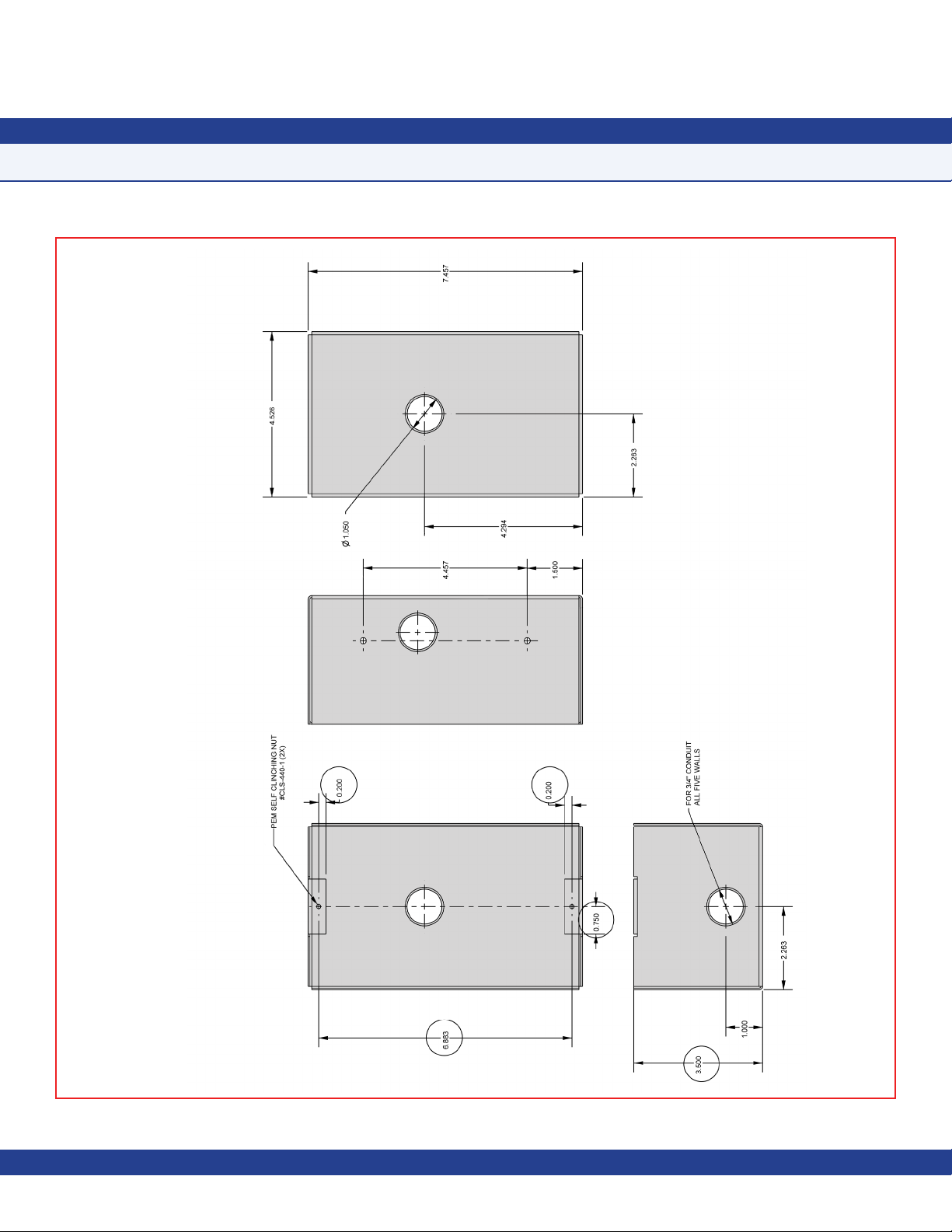
Integrated Flush Mount Wiring Box Dimensions
- 53 -
Page 61

Flush Mount Bracket Dimensions
- 54 -
Page 62

Thin Mount Wiring Box Dimensions
- 55 -
Page 63

Notes
- 56 -
Due to continuous improvement, TRIATEK reserves the right to change product specifications without notice.
Page 64

FLOW DIAGRAMS
Unit Setup Menu Tree
- 57 -
JCI reserves the right to change product specifications without notice.
Page 65

FLOW DIAGRAMS
System Setup Menu Tree
- 58 -
Due to continuous improvement, TRIATEK reserves the right to change product specifications without notice.JCI reserves the right to change product specifications without notice.
Page 66

FLOW DIAGRAMS
System Setup Menu Tree
- 59 -
Due to continuous improvement, TRIATEK reserves the right to change product specifications without notice.
JCI reserves the right to change product specifications without notice.
Page 67
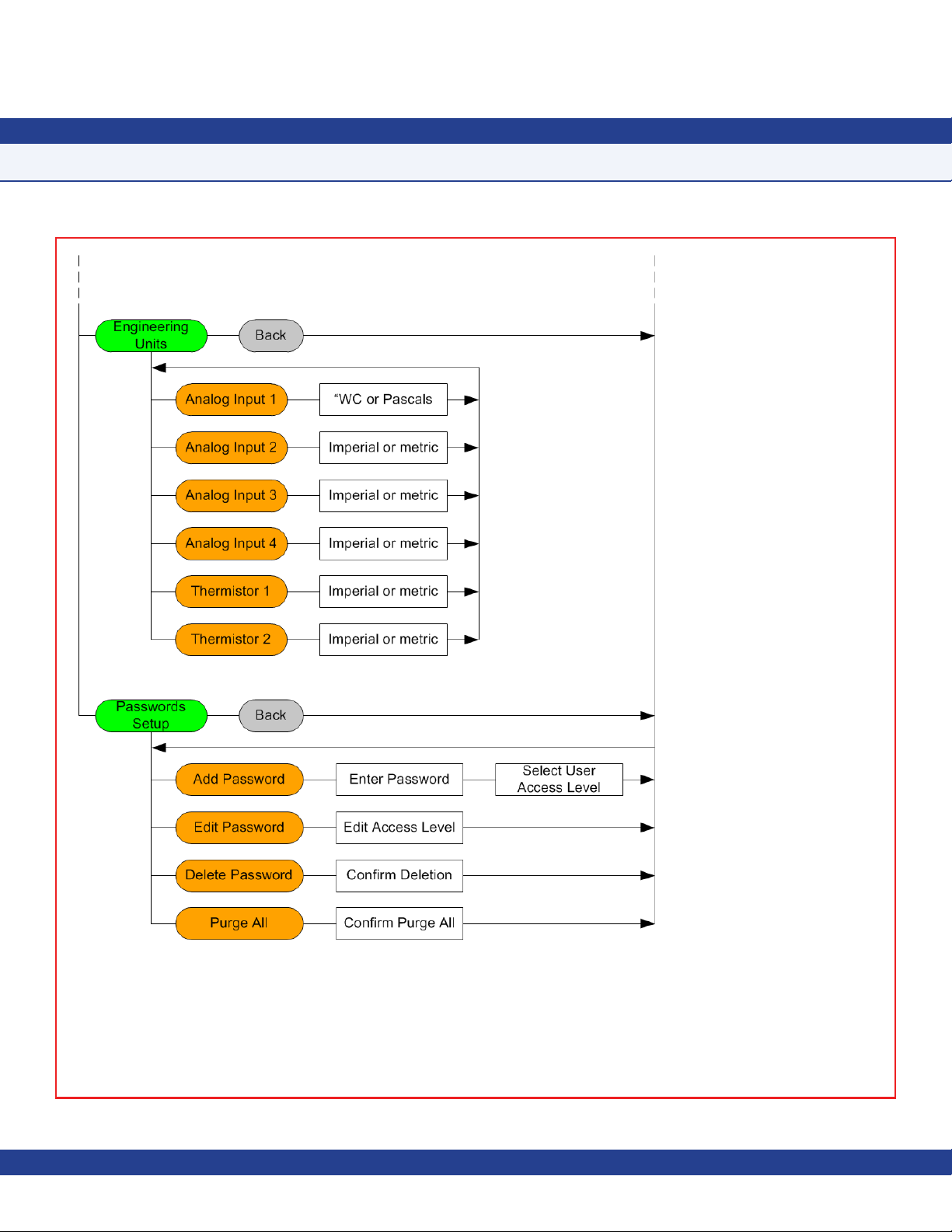
FLOW DIAGRAMS
System Setup Menu Tree
- 60 -
Page 68

FLOW DIAGRAMS
Display Setup Menu Tree
- 61 -
Due to continuous improvement, JCI reserves the right to change product specifications without notice.
Page 69

FLOW DIAGRAMS
Diagnostics Menu Tree
- 62 -
Due to continuous improvement, TRIATEK reserves the right to change product specifications without notice.Due to continuous improvement, JCI reserves the right to change product specifications without notice.
Page 70

FMS-1655 Room Pressure Controller (BACnet
Installation Manual
LB-FMS1655-F01
LB-FMS1655-F02
LB-FMS1655-S01
LB-FMS1655-S02
Code No. LIT-12013117, Rev. A
®
/ N2 only products)
Issued August 2018
LB-FMS1655-F03
LB-FMS1655-F04
LB-FMS1655-F10
LB-FMS1655-F11
LB-FMS1655-F12
LB-FMS1655-F13
+1-414-524-1200
Johnson Controls
5757 N. Green Bay Ave.
P.O. Box 591
Milwaukee, WI 53201
LB-FMS1655-S03
LB-FMS1655-S04
LB-FMS1655-T01
LB-FMS1655-T02
LB-FMS1655-T03
LB-FMS1655-T04
JCI CMS-1655
Central Monitoring Station
The Next Generation in Critical Airow Controls
The Next Generation in Critical Airow Controls
JCI FMS-1655
JCI 1650
 Loading...