

Page 1

Smart
THERMOSTAT
Installaon Manual
Page 2
Thanks for inving KONOTM into your home. The setup process is easy.
All you need to do is follow these simple steps and you’ll be on your
way to saving energy and making your home even more comfortable.
[Drill]
LUX Products oers installaon and product videos
Please visit LuxProducts.com/videos or visit our YouTube channel
LUX Products Corporaon. To contact LUX Technical Support please call
856.234.8803.
Para ver estas instrucciones en español, por favor visite
LuxProducts.com/KONOmanualsSP
Page 3
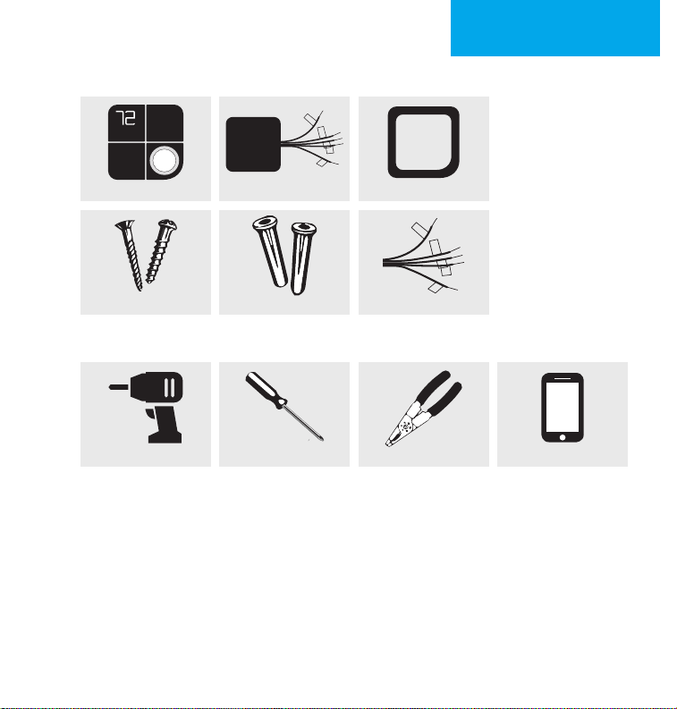
What’s in the box?
1. START HERE
KONO Smart
Screws Wall Anchors
LUX Power Bridge
TM
Trim Plate
Wiring Labels
Tools Needed
Drill Oponal: Wire Stripper SmartphonePhillips Screwdriver
Table of Contents
1. Start Here ......................................................................................2-6
2. Installing with a C-Wire................................................................7-10
3. Installing without a C-Wire ........................................................ 11-14
4. Connecng to the Network .......................................................15-19
5. Appendix....................................................................................20-23
LuxProducts.com | 3
Page 4
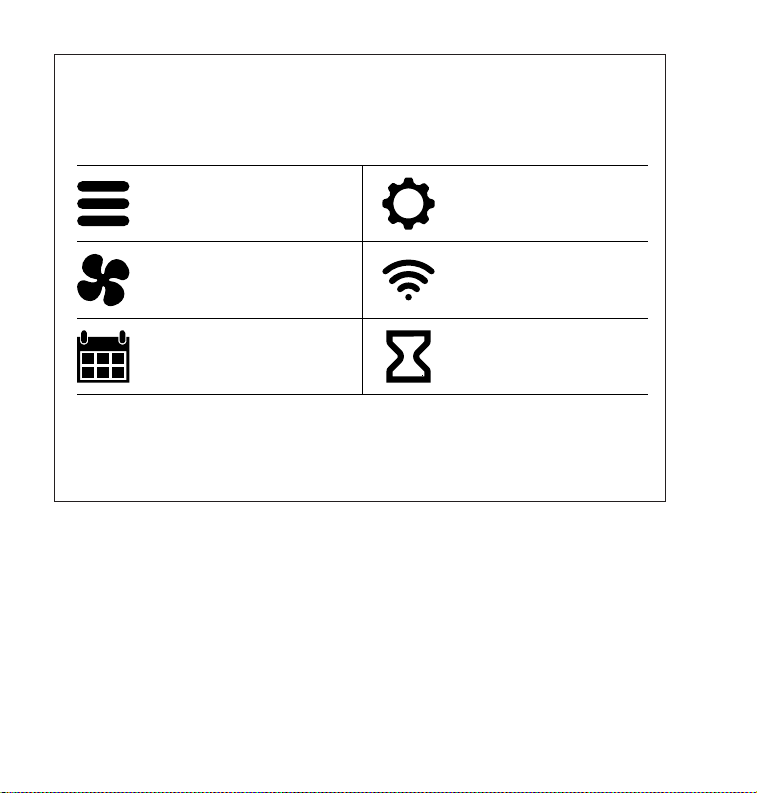
Press the knob when the thermostat is idle to
view the menu. Rotate the knob to select an
opon and press again to conrm.
System Mode
Fan Mode
Run Schedule
Installaon
Sengs
Network
Connecon
System
Preparing
For more informaon about
installaon sengs, please visit
LuxProducts.com/KONOmanual
Behind KONO’s Décor-snapTM cover you will see a small, removable
“quick guide” to installaon and an icon-key label. The icons represent
the display icons of your KONO Smart. You will also nd important
informaon for HomeKitTM and WiFi setup.
This manual is a comprehensive guide to installaon and wiring.
4 | 856.234.8803
Page 5
1. START HERE
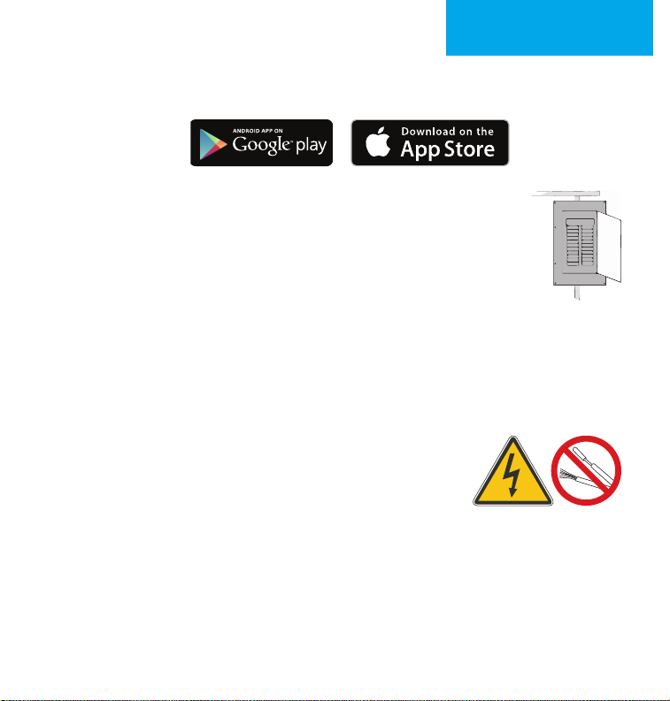
Step 1.1: Download the LUX Products App to your mobile device and
create an account.
Step 1.2: Now set your phone aside and turn o the power
at the circuit breaker to both your heang and cooling
systems before performing any wiring.
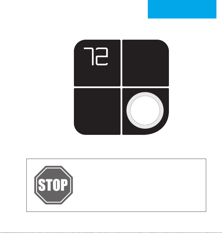
Step 1.3: Conrm that your heang and cooling system is powered
down by changing the temperature on your thermostat.
Hint: Your system should not make any noise and you should not feel
any air exing your vents.
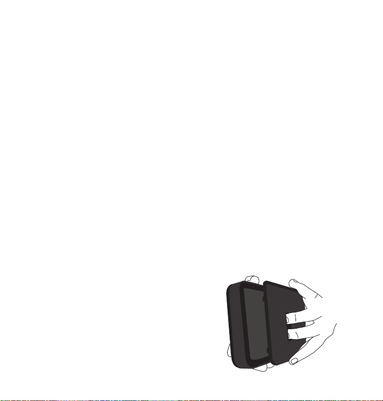
Step 1.4: Remove the front of your old thermostat
from its base. If you see thick black wires, wire
nuts, or any labels that say 120-240VAC or High
Voltage, your system is not compable with KONO
Smart. Please call LUX Technical Support at
856.234.8803 before proceeding with your
installaon. If you do not see any high voltage labels
or wires, you can connue with your installaon.
HIGH
VOLTAGE
LuxProducts.com | 5
Page 6
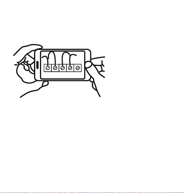
Step 1.5: Use the included wire labels to mark which wire is connected
to each terminal in your old thermostat. Take a picture of your current
wiring layout – it may be helpful to reference this picture later.
Step 1.6: Conrm if you have a C-Wire. If you do, please turn to the
next page. If you do not, please skip ahead to page 11.
6 | 856.234.8803
Page 7
INSTALLATION WITH
STOP
C-WIRE2.
Installing with a C-wire
Before starng
Turn o the power at the circuit breaker to
both your heang and cooling systems before
performing any wiring. You will not need the
included LUX Power Bridge.
LuxProducts.com | 7
Page 8
Installaon with C-wire
Step 2.1: Idenfy your system conguraon (see wiring diagrams in
appendix). Potenal conguraons include:
• Convenonal 1H/1C (Y, G, W, R, C)
• Convenonal 2H/1C (Y, G, W, W2, R, C)
• Heat Pump Single-Stage (Y, G, R, O/B, C)
• Heat Pump with auxiliary heat or dual fuel (Y, G, R, O/B, W, C)
If you have only one R wire, please use the RH terminal. If you have a
dierent conguraon other than what is listed above, please call LUX
Technical Support for help with your installaon.
Step 2.2: Remove each wire from its terminal – make sure that they
don’t fall down back into the wall.
Step 2.3: Remove the mounng screws from the base of the old
thermostat. Remove the base from the wall.
Step 2.4: If you would like to use the trim plate or wall anchors,
you can install them now.
Step 2.5: Separate KONO Smart from its
base. Pull the wires from your wall through
the center hole of the KONO Smart base.
Secure the base to the wall using the
included mounng hardware.
8 | 856.234.8803
Page 9

INSTALLATION WITH
C-WIRE2.
Opon 1 - Convenonal (furnace) Systems:
Step 2.6f: Following the terminal labels
marked “Convenonal” on the thermostat
base, press the lever and insert each
labeled wire into the top hole of the
corresponding terminal.
Step 2.7f: If you have both an RC and RH wire present, then remove the
red cap next to the reset buon. You can now skip ahead to step 2.8.
Opon 2 - Heat Pump Systems:
Step 2.6hp: Following the terminal labels
marked “Heat Pump” on the thermostat base
and referencing your wiring photo, press the
lever and insert each labeled wire into the top
hole of the corresponding terminal.
If your old thermostat did not have a W1 wire but did have a W2 wire,
please insert the W2 wire into the W1 terminal.
Step 2.7hp: If you have both an O wire and a B wire
(i.e. in a Trane system), please install the B wire to the “C” terminal.
For more detailed direcons, please see the wiring diagrams in the
appendix or call LUX Technical Support.
CONVENTIONAL C W1 W2
HEAT PUMP C W1 OB
POWER BRIDGE 1 4 2
CONVENTIONAL C W1 W2
HEAT PUMP C W1 OB
POWER BRIDGE 1 4 2
LuxProducts.com | 9
Page 10

Installaon with C-wire
Step 2.8:
Securely fasten KONO Smart onto its base. Once it has clicked
into place, return power to your heang and cooling system.
Step 2.9: Aer your thermostat powers up, you are ready to congure
KONO Smart for your heang and cooling system and connect to a
wireless network.
Please skip ahead to the “Connecng to the Network” secon of this
manual on page 15.
10 | 856.234.8803
Page 11

STOP
INSTALLATION WITHOUT
C-WIRE3.
Installing without a C-Wire
Using the Included LUX Power Bridge
1. Install and wire
your KONO
2. Install LUX Power Bridge
at your furnace
For installaon without C-wire,
you will need to access your furnace.
Before starng
Turn o the power at the circuit breaker to
both your heang and cooling systems before
performing any wiring.
LuxProducts.com | 11
Page 12

Installaon without C-wire
Hint: helpful videos showing how to wire a thermostat with the LUX
Power Bridge are available at LuxProducts.com/videos
Step 3.1: Starng at your thermostat, conrm that you have one of the
system conguraons listed below:
• Convenonal 1H/1C (Y, G, W, R)
• Convenonal 2H/1C (Y, G, W1, W2, R)
If you have a dierent conguraon other than what is listed above,
please call LUX Technical Support for help with your installaon.
Step 3.2: Remove each wire from its terminal – make sure that they do
not fall down back into the wall.
Step 3.3: Remove the mounng screws from the base of the old
thermostat. Remove the base from the wall.
Step 3.4: If you would like to use the trim plate or wall anchors, you can
install them now.
12 | 856.234.8803
Page 13

INSTALLATION WITHOUT
C-WIRE3.
Step 3.5: Separate KONO Smart from its base.
Pull the wires from your wall through the center
hole of the KONO Smart base. Secure the base to
the wall using the included mounng hardware.
Step 3.6: Following the terminal labels marked
“Power Bridge” on the thermostat base,
press the lever and insert each labeled wire
into the top hole of the corresponding
terminal. Connect as follows:
• Y Wire Terminal 1
• W Wire Terminal 2
• R Wire Terminal 3
• G Wire Terminal 4
Step 3.7: Securely fasten KONO Smart
onto its base.
Step 3.8: Go to your furnace – remove the door
or panel and locate your control board or transformer. In most cases,
there should be four wires running from the furnace to your thermostat
– Y, G, W, and R. If you have addional wires, leave them as is.
CONVENTIONAL C W1 W2
HEAT PUMP C W1 OB
POWER BRIDGE 1 4 2
LuxProducts.com | 13
Page 14

Step 3.9: i) Matching the leers, label the wires connected to your
Y G W R C
1(Y)
4(G)
2(W)
3(R)
Y G W R C
1(Y)
4(G)
2(W)
3(R)
C
Y G W R C
1(Y)
4(G)
2(W)
3(R)
C
furnace with the included white Power Bridge wire
labels. Take a picture of the wiring at your control board.
ii) Disconnect these wires from the control board.
iii) Open the Power Bridge and insert each of your old wires
into the corresponding numbered terminals in the Power
Bridge.
iv) Finally, insert the Power Bridge wires (with the colored
labels) into the corresponding terminals on your furnace
control board.
i) ii) iii) iv)
Furnace Furnace Furnace
4(G)
Y G W R C
1(Y)
Y G W R C
1(Y)
2(W)
4(G)
3(R)
C
3(R)
2(W)
4(G)
1(Y)
3(R)
2(W)
4(G)
1(Y)
Y G W R C
1(Y)
2(W)
4(G)
C
3(R)
Step 3.10: Secure the LUX Power Bridge to your furnace. If you had to
remove a panel or door to access your control panel, replace it now.
Step 3.11: Return power to your heang and cooling system. If your
system, including your thermostat, does not power up please call LUX
Technical Support.
Aer KONO Smart powers up, you are ready to congure it for your
heang and cooling system and connect to a wireless network.
14 | 856.234.8803
Page 15

CONNECTING TO THE
NETWORK4.
Connecng to the Network
Step 4.1: Aer your thermostat powers up, it will guide you through the
inial system conguraon. Use the knob to change opons and press
the knob to conrm your selecon.
First you will need to set your system type
(F) for Furnace or Boiler (HP) for Heat Pump
then then
Set the fan type to Gas
(most common), Electric
(for systems without gas or oil),
or Boiler (no fan)
Note: For advanced sengs please visit LuxProducts.com/KONOmanual
or call LUX Technical Support.
Step 4.2: Aer conrming your system
sengs, KONO Smart will ask if you
would like to connect to the network.
Select “ON” to begin connecon or
“OFF” to connect later. If you wish to
connect, please make sure that you have downloaded the LUX Products
App to your smartphone and created an account.
Set the valve type to O or B –
look at the photo of your wiring
to see which you have
Hint: If you are having trouble, please see our instruconal video at
LuxProducts.com/videos
LuxProducts.com | 15
Page 16

Step 4.3: Aer selecng “ON”, KONO
Font a nd font s ize is Ar ial 5pt .
KONO3
DDMMYYV
Example
QR-CODE INFORMATION
Smart will display “01”. You will then
need to select “iOS” if you are using an
Apple® device or “And” if you are using
an Android® device.
Step 4.4: Aer selecng “iOS” or “And”,
your thermostat will display a large
“02”, then “03”. Remove your DécorsnapTM cover.
Press the knob when the thermostat is idle to
view the menu. Rotate the knob to select an
System Mode
Fan Mode
Run Schedule
LuxProducts.com/KONOmanual
COOL
ON
123-45-678
WIFI Name:
LUX KONO-1a-24
WIFI Password:
KONO3
260517A
12345678
HomeKit
Code
Android
WiFi Code
Network
System
Preparing
16 | 856.234.8803
Page 17

CONNECTING TO THE
NETWORK4.
iOS® (iPhone® or iPad®)
Open your LUX App, tap the + icon to add a new accessory, then select
the accessory ID that starts with LUX KONO to start the connecon
process.
Follow the instrucons in the App.
If you need to cancel the joining process at any me, simply press and
hold the knob for 5 seconds.
Locate your accessory’s HomeKit Code under the Décor-snap cover.
When prompted, use your iPhone or iPad’s camera to scan the code.
Aer the App scans the code, your App and thermostat will handle the
remaining steps in the connecon process.
COOL
ON
When you see the thermostat’s idle screen, it
means you are connected. You can now replace the
Décor-snap cover.
To control this HomeKit-enabled accessory, iOS 10.3 or later is
recommended.
LuxProducts.com | 17
Page 18

ANDROID®
Open your LUX App, tap the + icon to
add a new thermostat. When prompted
by the LUX App, please use your phone’s
WiFi sengs to join your LUX KONO’s WiFi
network. The network name and password
can be found under the Décor-snap cover.
Aer connecng your thermostat to the
network, please return to the App and
select your home WiFi network from the
list and enter your password.
Please make sure your phone reconnects to your home WiFi network
and then return to the LUX App. From this point your thermostat and
App will handle the remaining steps in the connecon process.
COOL
ON
18 | 856.234.8803
When you see the thermostat’s home screen, it
means you are connected. You can now replace the
Décor-snap cover.
Page 19

CONNECTING TO THE
NETWORK4.
Congratulaons!
Installaon is complete and your KONO is ready to go. Now let’s save
some energy and make your home more comfortable.
Personalize your KONO Smart.
It’s more than a thermostat, it’s décor! Match KONO to your style by
simply changing the Décor-snap cover. Check out our wide variety of
designer colors and nishes at LUXProducts.com/shopcovers.
Hibiscus
Red
Sea
Green
Deep
Blue
Midnight
Black
Wood
Grain
LuxProducts.com | 19
Page 20

Convenonal System With C-Wire Wiring Diagram
Heat Pump
Convenonal
C
Transformer
C
Power Bridge
1
4
W1
O/B
G
Y1
RC
RH
2
Thermostat
3
Furnace
HEAT (STAGE 1)
HEAT (STAGE 2)
FAN
COOL
W1
W2
G
Y1
RC
RH
Notes:
• The W2 terminal is used for 2 stage heang systems only
• If you have both an RH and RC wire, please remove the red cap from the back of
the thermostat
20 | 856.234.8803
Page 21

Heat Pump System With C-Wire Wiring Diagram
Convenonal
C
Transformer
C
Heat Pump
APPENDIX5.
Power Bridge
1
4
W1
O/B
G
Y1
RC
RH
2
Thermostat
3
LuxProducts.com | 21
AUX / EMER Heat
CHANGEOVER VALVE
FAN
W1
W2
G
Heat Pump
COOL
Notes:
• The W1 terminal is used for Auxiliary/Emergency heat or on Dual Fuel systems
Y1
RC
RH
Page 22

LUX Power Bridge Wiring Diagram
Thermostat
LUX Power Bridge
COOL
FAN
HEAT (STG 1)
TRANSFORMER
Furnace
COMMON
Y
G
W
R
C
Heat Pump
Convenonal
1(Y)
1
2(W)
2
3(R)
3
4(G)
4
C
W1
W2
G
Y1
W1
O/B
G
Y1
C
Power Bridge
1
4
2
HEAT STG2
Notes:
• If you have a heat pump or dual transformer system, please call LUX Tech support.
• If you have any wires on your furnace not shown here, please leave them as is.
22 | 856.234.8803
RC
RH
RC
RH
3
Page 23

APPENDIX5.
Apple HomeKit™
Use of the Works with Apple HomeKit logo means that an electronic accessory has been designed to connect
regulatory standards.
Apple is a trademark of Apple Inc., registered in the U.S. and other countries. HomeKit is a trademark of Apple Inc.
FCC Part 15C
could void the user’s authority to operate the equipment.
NOTE: This equipment has been tested and found to comply with the limits for a Class B digital device, pursuant to
following measures:
• Reorient or relocate the receiving antenna.
• Consult the dealer or an experienced radio/TV technician for help.
Industry Canada Regulatory Informaon
Le présent appareil est conforme aux CNR d’Industrie Canada applicables aux appareils radio exempts de licence.
LuxProducts.com | 23
Page 24

LUX PRODUCTS CORPORATION
Philadelphia, PA 19112 USA
LuxProducts.com
Designed in Philadelphia.
54066
 Loading...