

Johnson Controls JXHX1252N, JXHX2452N, JXHX1852N, JXHX3652N, JXMHX1852N Engineering Manual
...Page 1
MINI 2-WAY
VARIABLE REFRIGERANT FLOW (VRF) SYSTEM
ENGINEERING GUIDE New Release Form 121.00-EG1 (512)
MINI 2-WAY
VARIABLE REFRIGERANT FLOW (VRF) SYSTEM
Issue Date:
May 25, 2012
Page 2

IMPORTANT!
FORM 121.00-EG1
ISSUE DATE: 5/31/2012
JOHNSON CONTROLS
2
READ BEFORE PROCEEDING!
GENERAL SAFETY GUIDELINES
This equipment is a relatively complicated apparatus.
During installation, operation maintenance or service,
individuals may be exposed to certain components or
conditions including, but not limited to: refrigerants,
materials under pressure, rotating components, and
both high and low voltage. Each of these items has the
potential, if misused or handled improperly, to cause
bodily injury or death. It is the obligation and responsibility of operating/service personnel to identify and
recognize these inherent hazards, protect themselves,
and proceed safely in completing their tasks. Failure
to comply with any of these requirements could result
in serious damage to the equipment and the property in
which it is situated, as well as severe personal injury or
death to themselves and people at the site.
This document is intended for use by owner-authorized
operating/service personnel. It is expected that these
individuals possess independent training that will enable them to perform their assigned tasks properly and
safely. It is essential that, prior to performing any task
on this equipment, this individual shall have read and
understood this document and any referenced materials. This individual shall also be familiar with and
comply with all applicable governmental standards and
regulations pertaining to the task in question.
CHECK OF DENSITY LIMIT
The room in which the air conditioner is to be installed requires a design that in the event of refrigerant gas leaking out, its density will not exceed a
set limit.
The refrigerant (R410A), which is used in the airconditioner, is safe, without the toxicity or combustibil-
ity of ammonia, and is not restricted by laws imposed
to protect the ozone layer. However, since it contains
more than air, it poses the risk of suffocation if its density should rise excessively. Suffocation from leakage
of refrigerant is almost non-existent.
With the recent increase in the number of high density
buildings, however, the installation of multi air conditioner systems is on the increase because of the need
for effective use of floor space, individual control, energy conservation by curtailing heat and carrying power, etc. Most importantly, the multi air conditioner system is able to replenish a large amount of refrigerant
compared to conventional individual air conditioners.
If a single unit of the multi air conditioner system is
to be installed in a small room, select a suitable model
and installation procedure so that if the refrigerant accidentally leaks out, its density does not reach the limit
(and in the event of an emergency, measures can be
made before injury can occur).
ASHRAE and the International Mechanical Code of
the ICC as well as CSA provide guidance and define
safeguards related to the use of refrigerants, all of
which define a Refrigerant Concentration Level (RCL)
of 25 pounds per 1,000 cubic feet for R410A refrigerant. For additional guidance and precautions related to
refrigerant safety, please refer to the following documents:
International Mechanical Code 2009 (IMC-2009) (or
more recently revised)
ASHRAE 15
ASHRAE 34
Page 3
INDOOR UNIT NOMENCLATURE
FORM 121.00-EG1
ISSUE DATE: 5/31/2012
3
JOHNSON CONTROLS
J UMHX 12 62N
SERIES
CAPACITY
SLIM CONCEALED DUCT TYPE
JOHNSON CONTROLS
OUTDOOR UNIT NOMENCLATURE
J CHX R 036 52N
CAPACITY
SALT-AIR DAMAGE RESISTANT
2-WAY FLOW MINI
JOHNSON CONTROLS
SERIES
OUTDOOR UNITS
KEY CLASS 36 52
JCHX Variable Refrigerant Flow
System
Refrigerant R410A is used in the outdoor units.
* Salt-Air Damage Resistant Specications.
JCHX03652N
JCHXR03652N*
JCHX05252N
JCHXR05252N*
INDOOR UNITS
KEY CLASS 7 9 12 15 18 24 36 48 54
JX 4-Way Air
Discharge
Semi-Concealed
JXM 4-Way Air
Discharge
Mini SemiConcealed
JA 1-Way Air Dis-
charge SemiConcealed
JU Concealed
Duct Type
JUM Slim Concealed
Duct Type
JD Concealed-
Duct High
Static Pressure
JT Ceiling-
Mounted
JK Wall-Mounted
Type
JF Floor-Standing
Type
JFM Concealed-
Floor Standing
Type
JAHX0752N JAHX0952N JAHX1252N
JUHX0762N JUHX0962N JUHX1262N JUHX1562N JUHX1862N JUHX2462N JUHX3662N JUHX4862N JUHX5462N
JUMHX0762N JUMHX0962N JUMHX1262N JUMHX1562N JUMHX1862N
JKHX0752N JKHX0952N JKHX1252N JKHX1862N JKHX2452N
JFHX0762N JFHX0962N JFHX1262N JFHX1562N JFHX1862N JFHX2462N
JFMHX0762N JFMHX0962N JFMHX1262N JFMHX1562N JFMHX1862N JFMHX2462N
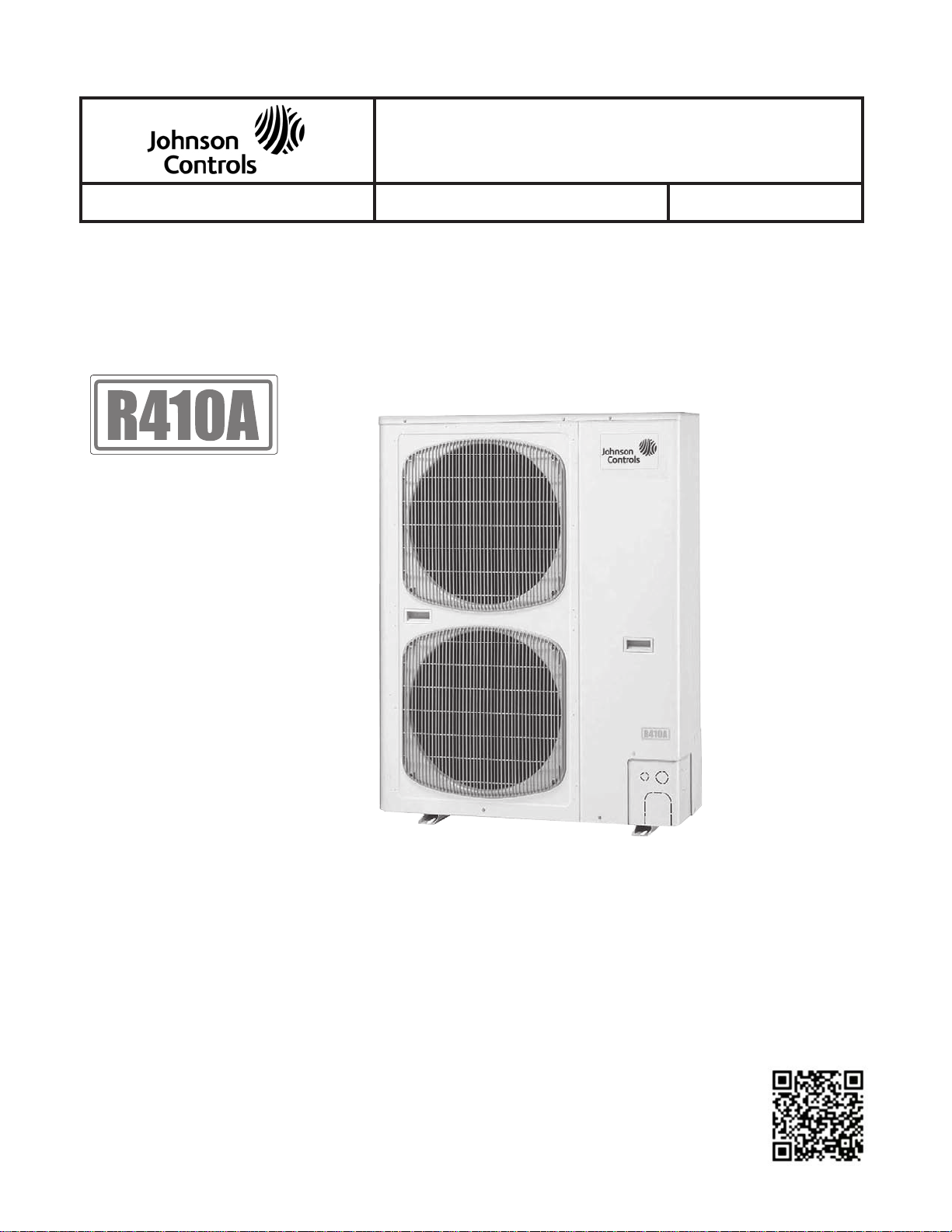
JXHX1252N JXHX1852N JXHX2452N JXHX3652N
JXMHX1252N JXMHX1852N
JDHX3652N JDHX4852N
JTHX1252N JTHX1852N JTHX2452N
Page 4

TABLE OF CONTENTS
FORM 121.00-EG1
ISSUE DATE: 5/31/2012
JOHNSON CONTROLS
4
INTRODUCTION .......................................................................................................................................................5
1. OFFERINGS ........................................................................................................................................................14
2. OUTDOOR UNIT DIMENSIONS AND SPECIFICATIONS .................................................................................17
3. INDOOR UNIT DIMENSIONS AND SPECIFICATIONS .....................................................................................27
4-Way Air Discharge Ceiling Semi-Concealed, Standard And Mini (JX, JXM Type) ......................................26
1-Way Air Discharge Ceiling Semi-Concealed (JA Type) ...............................................................................47
Slim Concealed Duct, Standard and Slim (JU, JUM Type) ............................................................................56
Concealed Duct High Static Pressure (JD Type)............................................................................................94
Ceiling Mounted Exposed Horizontal (JT T ype) ...........................................................................................101
Wall Mounted Exposed (JK Type) ................................................................................................................ 111
Floor Exposed (JF Type) ............................................................................................ ..................................124
Floor Concealed (JFM Type) ........................................................................................................................139
4. FRESH AIR INTAKE, SEMI-CONCEALED DUCT AND CONCEALED DUCT TYPES ...................................156
5. ELECTRICAL WIRING .....................................................................................................................................158
6. OUTDOOR UNIT WIRING DIAGRAMS ............................................................................................................168
7. INDOOR UNIT WIRING DIAGRAMS ................................................................................................................171
8. CAPACITY RATIO OF OUTDOOR UNITS .......................................................................................................196
9. COOLING CAPACITY OF INDOOR UNITS .....................................................................................................204
Note: 1. All data herein is subject to change without notice.
2. Drawings and performance data should not be used for submittal purposes
Page 5

INTRODUCTION
FORM 121.00-EG1
ISSUE DATE: 5/31/2012
5
JOHNSON CONTROLS
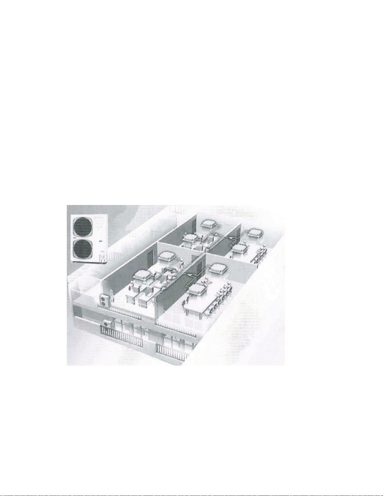
Suitability. Johnson Controls Mini 2-way Variable Refrigerant Flow (VRF) system is ideal for commercial office buildings subject to diverse loads and
varying occupant levels. Also, the 2-way VRF system
is ideal for schools, hotels, nursing homes and other
commercial living spaces where occupants will want
to control the temperature setting in their zone. In all
cases the system runs quietly, for a comfortable, productive environment.
Zone Control.
In buildings with multiple zones that
require separate comfort controls, you need options.
Johnson Controls Mini 2-way (VRF) systems give you
the heating and cooling flexibility you need, combined
with the reliability and energy efficiency you expect
from Johnson Controls. You get the freedom to create
comfortable, efficient buildings, without being limited
by ductwork runs.
Flexibility.
Johnson Controls Mini 2-way VRF systems offer multiple configurations for both new and
existing buildings. Multi-zone temperature control allows the system to handle diverse heating and cooling
loads, while giving occupants the ability to adjust temperature to satisfy their individual comfort needs. In
addition, variable refrigerant flow heating and cooling
uses energy efficiently, because VRF uses only refrigerant without air or water as a heat transfer medium.
Installation.
Johnson Controls Mini 2-way VRF
systems are modular which are easy to transport and
install. As remodeling occurs and building extensions
are planned, the VRF systems modularity allows to
simply add on to the system within the system parameters.
Control.
Johnson Controls Mini 2-way VRF systems are available with a variety of zone controls and
network controls that are responsive and provide immediate response to changes in zone loads. With wired
controls, wireless controls and a network portal that
supports BACnet®, LONWORKS® and Johnson Controls N2 protocols, the Mini 2-way VRF system will
have the solution to meet the needs of the owners and
tenants.
Page 6
JOHNSON CONTROLS Mini 2-WAY VARIABLE
FORM 121.00-EG1
ISSUE DATE: 5/31/2012
JOHNSON CONTROLS
6
REFRIGERANT FLOW SYSTEM BENEFITS
Johnson Controls Mini 2-way Variable Refrigerant
Flow (VRF) systems are easy to select with flexibility
built in to the unit choices. With responsive controls
and advanced inverter controlled compressor technology, they offer immediate response to changes in zone
loads with the compressor precisely delivering the right
amount of refrigerant to each zone. VRF systems provide increased occupant comfort, with zone control, all
occupants enjoy consistent room temperature regardless of variations in load during the day. VRF systems
provide efficient operation resulting in high COP’s, in
excess of 4.0 at full load conditions.
Johnson Controls Mini 2-way VRF systems outdoor
units have a modular design and compact footprint,
choosing a Johnson Controls VRF system means easy
installation and commissioning. With multiple unit
connectivity, up to 9 indoor units can be connected to
one condensing unit and the system takes advantage
of building load diversity. Diversity ratios of 50% to
130% allow for a smaller outdoor unit. Johnson Controls Mini 2-way outdoor units come in 2 sizes, 3 ton
and 4.4 ton.
Page 7

OUTDOOR UNITS
FORM 121.00-EG1
ISSUE DATE: 5/31/2012
7
JOHNSON CONTROLS
• Ultra-quiet operation as low as 22 dBA
• Range from 3-4.4 tons
• 208/230 volt — single-phase power supply
• Modular design for increased capacity from com-
pact footprint
• Ultra quiet operation as low as 51d (dBA)
• Maximum piping lengths up to 984 feet
• Up to 9 indoor units can be connected
INDOOR UNITS
• Range from 7,500-48,000 btu
• 208/230 volt — single-phase power supply
•
Ceiling,wallandoormountedmodelsavailable
• Concealed, semi-concealed and exposed models
available
• All units can be controlled with any Johnson Controls VRF zone controller.
CONTROLS
• Variety of controls available, all provide control
of mode, temperature, on/off and fan speed
• Remote unit controls
• Optional wireless remote controls
• Optional system diagnostics capability
• Network controls available
• Network portal that supports BACnet
®
, LON-
WORKS® and Johnson Controls N2 protocols.
• Standard operation uses return air sensor, but can
beconguredtousethesensorinthecontroller.
Page 8
FEA TURES AND OPTIONS
FORM 121.00-EG1
ISSUE DATE: 5/31/2012
JOHNSON CONTROLS
8
• Flexible Piping Design:
Outdoor Unit Features and Options:
• Range from 3-4.4 tons
• 208/230V, Single Phase, 60Hz
• Environmentally responsible R-410A refrigerant
• Ultra quiet operation as low as 51dBA
• Modular design for easy installation and compact
footprint
• Up to 9 indoor units can be connected
• Wide Operating Range (Outdoor Ambient)
• Cooling 14 °F to 109 °F
• Heating -4 °F to 59 °F
• 656 Feet - Maximum Total Liquid Line
• 492 Feet - Maximum Outdoor To Most Dis-
tant Indoor Unit
• 164 Feet - Maximum Vertical Between Indoor and Outdoor (Outdoor Above Indoor)
• 131 Feet - Maximum Vertical Between Indoor and Outdoor (Outdoor Below Indoor)
Indoor Unit Features and Options:
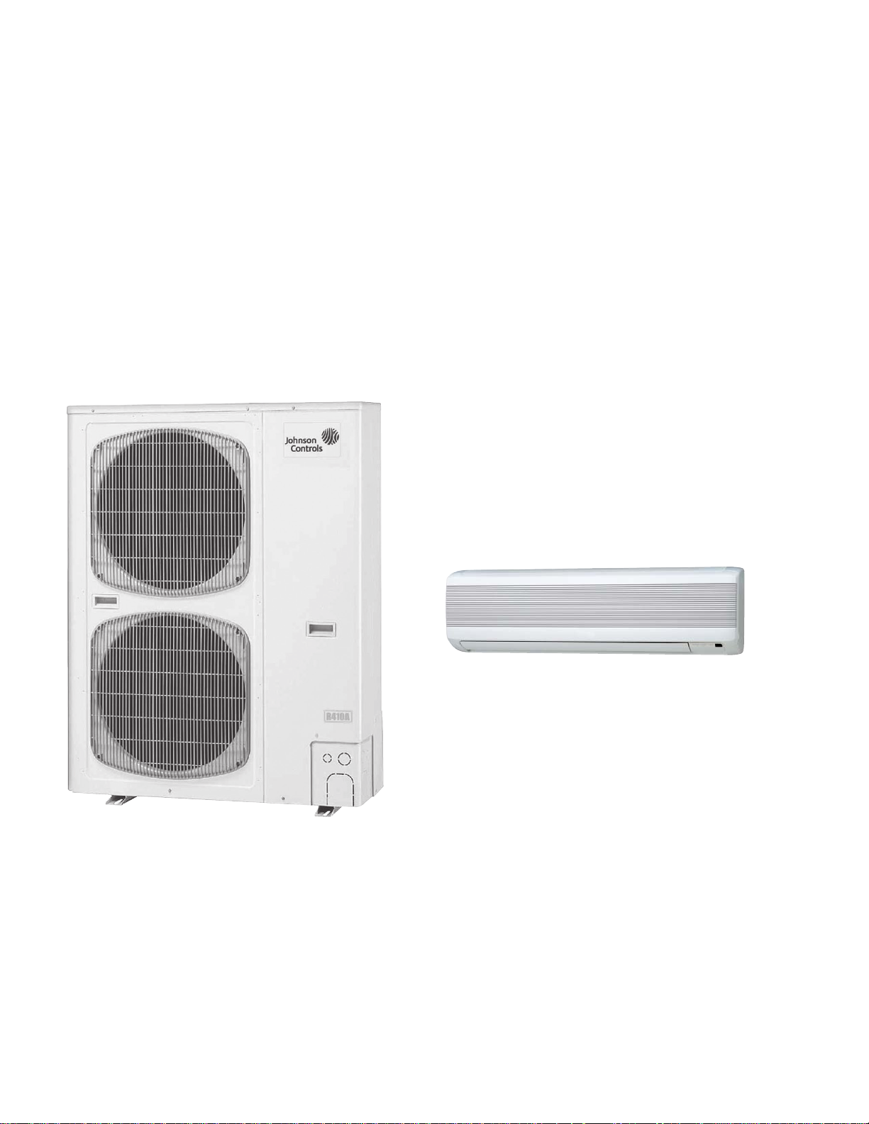
High Wall Mounted (JKHX Type)
• Lowest indoor unit cost per Btuh of cooling
• Surface mounts on walls
• Bottom discharge – should be mounted at least 5’
abovetheoorand12”fromceiling
• Wireless remote ready – comes with built-in wire-
less receiver
•
Anti-moldwashablelter(notMERVrated)
• 3-speed AC motor (not ECM)
• Condensate pump not included
JKHX Series - High Wall Mounted Indoor Unit
LD16391
Page 9
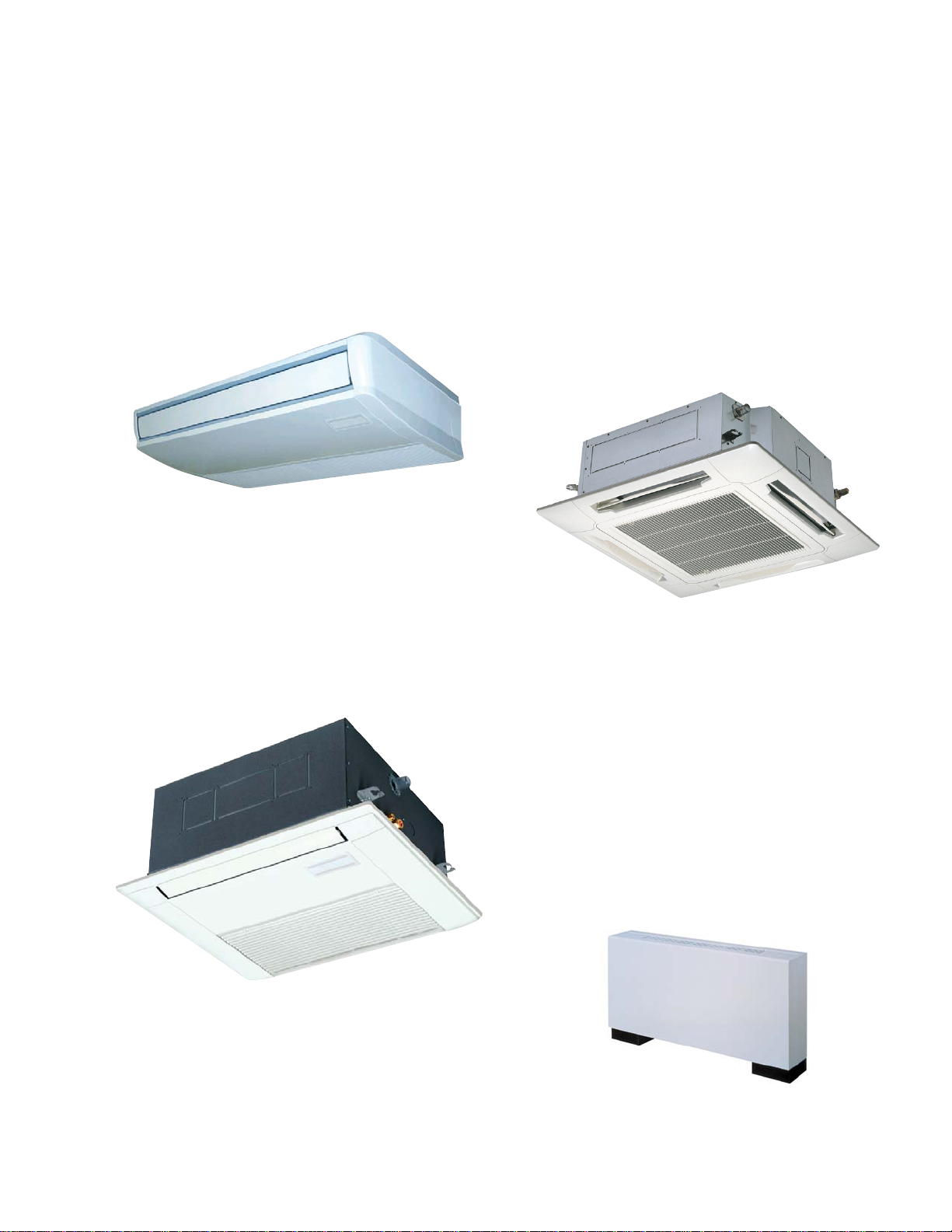
Ceiling Mounted Horizontal Exposed
FORM 121.00-EG1
ISSUE DATE: 5/31/2012
9
JOHNSON CONTROLS
(JTHX Type)
Low prole (8.5” tall) – great for commercial
•
spaces
• Mounts against ceiling with horizontal discharge
4 Way Air Discharge Semi-Concealed
Cassette (JXHX and JXMHX Type)
• Great for large spaces
1and1.5tonunitstinthespaceofa2’X2’ceil-
•
ing(JXMHXType)
•
Bottomreturn–canbemountedushwithwall
• Anti-moldwashablelter(notMERVrated)
• 3-speed DC motor (ECM)
• Condensate pump not included
JTHX Ceiling Mounted - Horizontal Exposed
1 Way Air Discharge Semi-Concealed
Cassette (JAHX Type)
Only13”tall–tsintightceilingplenums
•
• Anti-moldwashablelter(notMERVrated)
• 3-speed DC motor (ECM)
• Condensate pump built in
LD16392
• 1, 1.5, 2 and 3 ton units available in 30" x 30" unit
size(JXHXType)
• Individual louvers can be disabled for use in cor-
ners
Anti-moldwashablelter(notMERVrated)
•
• 3-speed DC motor (ECM)
Condensatepumpwith25”liftbuiltin
•
LD16395
JXHX 4-Way Air Discharge - Semi-Concealed Cassette
Vertical Floor Mounted, Exposed (JFHX Type)
• Good choice for renovations where replacing
heating only radiators
Airdischargedirectioniseasilycongured
•
• Front panel removes without tools for easy servic-
ing
Anti-moldwashablelter(notMERVrated)
•
• Pipes can be connected to either side of the unit
from the bottom or rear
• Wired controller can be mounted in the unit.
• Condensate pump not included
JAHX 1 Way Air Discharge - Semi-Concealed Cassette
LD16393
LD16394
JFHX - Vertical Floor-Mounted
Exposed
Page 10
Vertical Floor Mounted, Concealed
FORM 121.00-EG1
ISSUE DATE: 5/31/2012
JOHNSON CONTROLS
10
(JFMHX Type)
SameastheJFHXExposed,butwithoutcasing
•
• Low external static – discharge grille should be
attached to the unit discharge with very little or
no ducting
• Front panel removes without tools for easy servicing
Anti-moldwashablelter(notMERVrated)
•
• Pipes can be connected to either side of the unit
from the bottom or rear
• Condensate pump not included
Horizontal Concealed (JUHX Type)
High external static pressure up to 0.48” allows
•
enhancedltrationorlongerductruns
• Industry-leading low sound levels from 22 dBA
• Condensate pump built in
• Easy to install and maintain
• 3 speed AC motor (not ECM)
•
Standardround8”takeoffscaneasilyberemoved
if a rectangular plenum is desired
LD16399
JUHX - Horizontal Concealed
LD16397
JFMHX - Vertical Floor-Mounted
Concealed
Horizontal Concealed Slim (JUMHX Type)
Ultra-slimprole:7.9incheshighforallmodels
•
• DC fan motor greatly reduces power consumption
(ECM)
• Ideal for any application with short plenums
•
Anti-mold washable lters included, but use of
lterreturngrilleissuggested
• Easy maintenance and service by external electri-
cal box
• 0.16 in. w.g. static pressure enables ductwork to
betted
• Condensate pump built in
High Static Concealed Horizontal
(JDHX Type)
High external static pressure up to 0.70” allows
•
enhancedltrationorlongerductruns
• Can be used as 1:1 split system if required. Great
for large zones
• 3 speed AC motor (not ECM)
• Condensate pump not included
• This unit has a draw-through coil – a P-trap will
be required for the condensate
JUMHX - Horizontal Concealed Slim
LD16398
LD16400
JDHX - High-Static Horizontal Concealed
Page 11
Controller features and options:
FORM 121.00-EG1
ISSUE DATE: 5/31/2012
11
JOHNSON CONTROLS
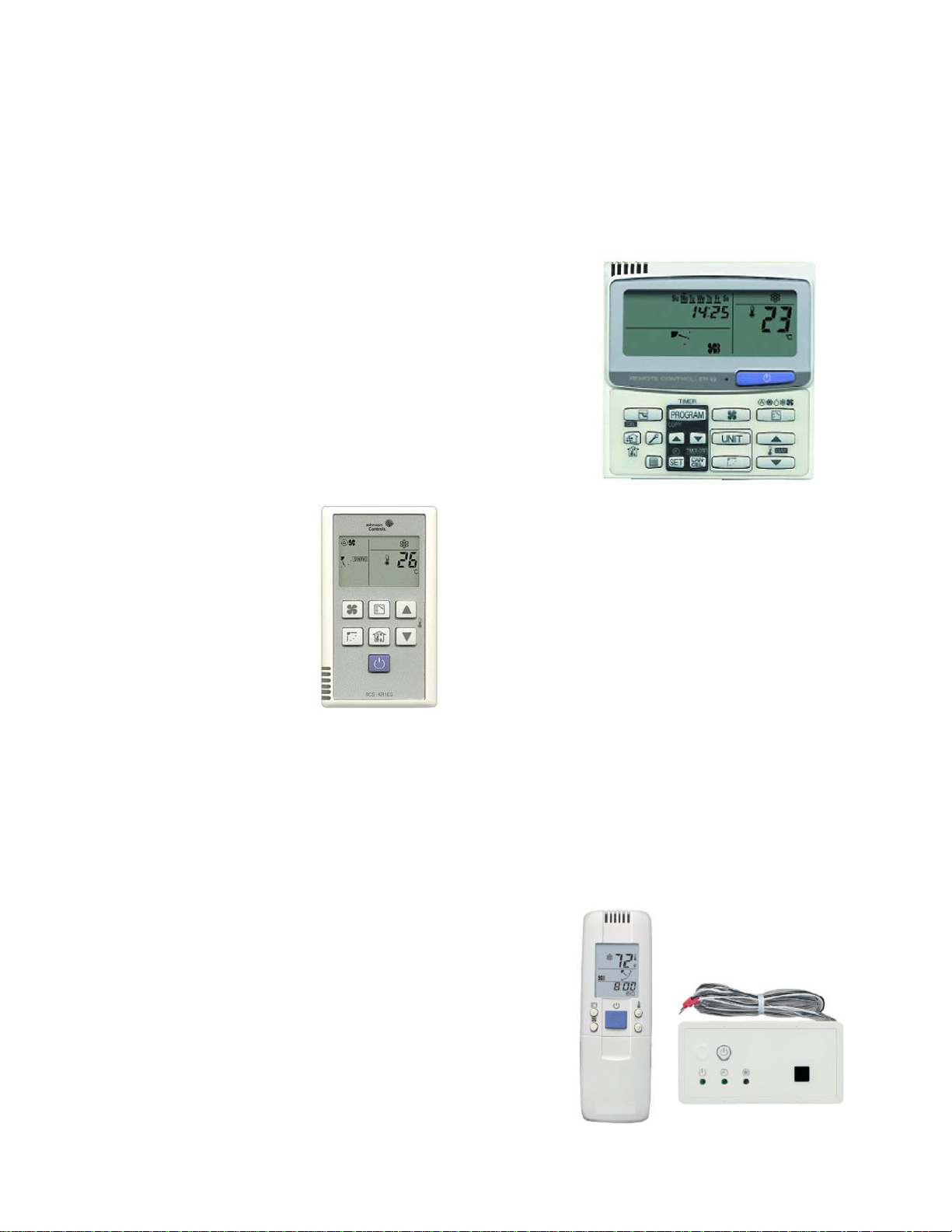
Simplied Wired Remote Control
• Cost effective individual zone control
• Thin and easy to read
• Simple to install – 2 low-voltage wires to the in-
door unit
• On / Off
• Mode Selection – choose heating, cooling, or auto
• Temperature set point
• Built in remote temperature sensor
•
Airowdirection(forindoorunitsthathavelou-
vers)
• Fan Speed Control
• 72 Hour Memory
Retention on Power Fail
• Mode Selection – choose heating, cooling, or auto
•
Airowdirection(forindoorunitsthathavelou-
vers)
• Fan speed control
• Controls up to 8 indoor units
LD16402
JRCS-TM80BGN - Standard Wired Remote Control
JRCS-KR1EGN - Simplified
Wired Remote Control
Standard Wired Remote Control
• Thin and Easy to Read
• Simple to install – 2 low-voltage wires to the in-
door unit
• Temperature set point
• 7 Day Timer, 6 time periods per day
• Temperature set-back
• Systems diagnostics capability (with connector
cable)
• Built in remote temperature sensor
LD16401
Wireless Remote Control
• Wireless unit for portable controls
• One remote can control many units
• On / Off
• Mode Selection – choose heating, cooling, or auto
• Temperature set point
•
Airowdirection(forindoorunitsthathavelou-
vers)
• Fan Speed Control
• Built in remote temperature sensor
•
Highwallmountedindoorunits(JKHX)havere-
ceivers built in, all other units require a receiver
thatmustbemountedintheeld
Wireless Remote Control
LD16497
Page 12
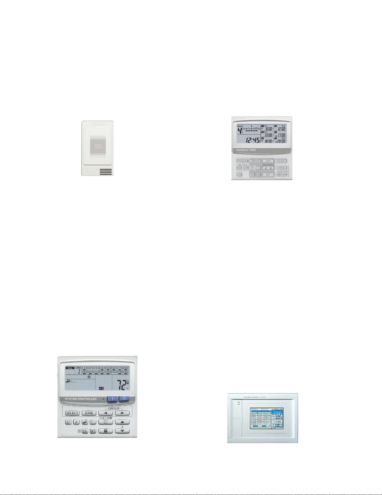
Wired Remote Sensor
FORM 121.00-EG1
ISSUE DATE: 5/31/2012
JOHNSON CONTROLS
12
Schedule Timer
• Cost effective individual zone control
• Thin and easy to read
• Simple to install – 2 low-voltage wires to the in-
door unit
• Once installed and wired, the EEPROM automatically changes the control from the return sensor to
the remote sensor
LD16404
JART-K45AGBN - Wired Remote Sensor
System Controller
• Capable of handling up to 64 indoor units
• 4 zones – each with up To 16 indoor units
• Up to 30 outdoor units to a single control line
• Can operate system without individual zone con-
trollers
• All zone control functionality is available
• Can take power from the U1/U2 system
• Important notes:
• No clock included
• Cannot be used for setback – addition of the
schedule timer only allows on/off control
• Timer controls up to 64 Units into 1,4, or 8 groups
• 7 Day Timer ,6 Time Periods/Day (On/Of f only , no
setback)
• 100 hour backup battery
• Usually tied to a System Controller, but can be
used stand-alone
LD16406
JSHA-TM64AGBN - Schedule Timer
Intelligent Controller
• Controls up to 128 units in two groups
• Up to 256 units / 4 groups with Communica-
tions Adapter
• 6.5 inch touch screen panel
• Web accessible
• Individual zone override
• Provides tenant billing data
• Available alarm contact
• Real time diagnostics
• Diagnostic history of system past & present
JSHA-KC64AGN - System Controller
LD16405
• Maximum installation of two System Controls
• Requires separate power supply
LD16407
Page 13
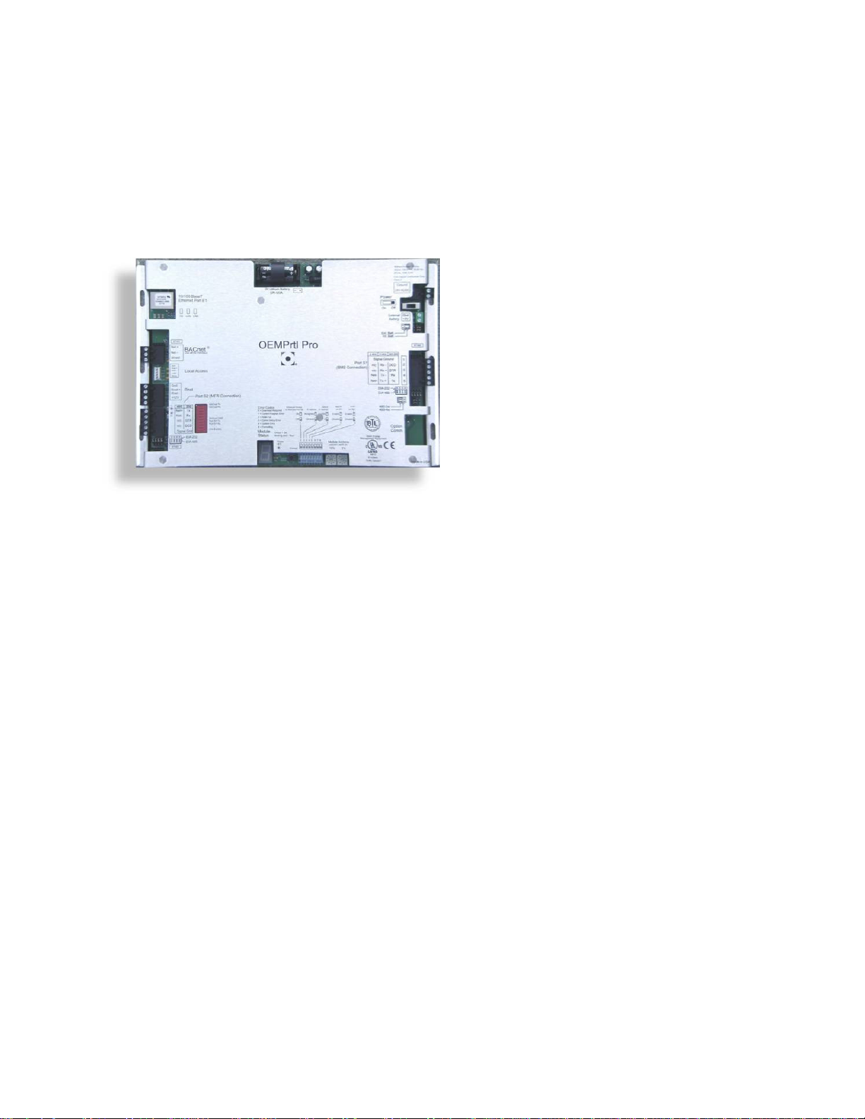
OEM Portal
FORM 121.00-EG1
ISSUE DATE: 5/31/2012
13
JOHNSON CONTROLS
• BAS to VRF interface
• LONworks
®
or BACnet
®
• Only way to control a VRF system with BAS
• This allows communication between the propri-
etary VRF controls network and the BMS
• Field labor is required to add this to the BMS
LD16496
Page 14
Indoor units
FORM 121.00-EG1
ISSUE DATE: 5/31/2012
JOHNSON CONTROLS
14
1. Offerings
Type
4-Way Air
Discharge SemiConcealed Type
(JX Type)
4-Way Air
Discharge Mini
Semi-Concealed
Type (JXM T ype)
1-Way Air
Discharge SemiConcealed Type
(JA Type)
Concealed Duct
Type
(JU Type)
Slim Concealed
Duct Type
(JUM Type)
Concealed Duct
High-Static
Pressure Type
(JD Type)
97 12 15 18 24 36 48 54
JXHX1252N JXHX1852N
JXMHX1252N JXMHX1852N
JAHX0752N
JUHX0762N JUHX1262NJUHX0962N JUHX1562N JUHX1862N JUHX2462N
JUMHX0762N JUMHX1262NJUMHX0962N JUMHX1562N JUMHX1862N
JAHX0952N JAHX1252N
JXHX2452N JXHX3652N
JUHX3662N JUHX4862N JUHX5462N
JDHX3652N
JDHX4852N
Ceiling-Mounted
Type
(JT Type)
Wall-Mounted
Type
(JK Type)
Floor-Standing
Type
(JF Type)
Concealed-Floor
Standing Type
(JFM Type)
JTHX1852NJTHX1252N JTHX2452N
JKHX0752N
JFHX0762N JFHX1262NJFHX0962N JFHX1562N JFHX1862N JFHX2462N
JFMHX0762N JFMHX1262NJFMHX0962N JFMHX1562N JFMHX1862N JFMHX2462N
JKHX0952N JKHX1252N JKHX2452NJKHX1862N
Page 15
Indoor units
FORM 121.00-EG1
ISSUE DATE: 5/31/2012
15
JOHNSON CONTROLS
96
96,000 (28.1)96/
108,000 (31.6)
Type
Capacity:
BTU/h (kW)
DC inverter unit
36 52
38,200 (11.2)
52,900 (15.5)
Cooling /
Heating
Outdoor
Unit
13-3/8
11-21/32
48-7/16
/ 42,700 (12.5)
6-
11/16
2-
3/4
1/2 1/2
25-31/32
8-5/8
Air intake
1/2
5-29/32
Air
discharge
37
1/2
4-
5/16
25/32
13/32
3-29/32
25/32
13/32
15-15/16
14-31/32
19/32
3-3/16
Air
discharge
/ 60,000 (17.6)
Air
intake
23/32
2-3/8
* Outdoor unit model name beginning with letters “JCHXR”
Refer to the Section 1. Salt-Air Damage Resistant Specications”.
6-13/16
5-1/2
7-3/4
4-23/32
6-9/16
2-25/32
JCHX03652/05252
JCHXR03652/05252*
JCHX03652N/05252N
JCHXR03652N/05252N*
23-5/8
22-9/16
5-9/16
1-13/32
2-3/8
4-11/32
5-1/8
4-3/4
2-27/32
7-25/32
6-5/8
Page 16
Salt-Air Damage Resistant Specifications (Anti-Corrosion)
FORM 121.00-EG1
ISSUE DATE: 5/31/2012
JOHNSON CONTROLS
16
Relevant Parts Material Standard Specifications
Salt-Air Damage
Resistant Specifications
Outdoor unit model name
beginning with letters "CHXR"
Outer box/side plate/
drain pan
between the stud
Base frame
Fan guard
Fin Aluminum No treatment
Tube Copper No treatment Zinc rich treatment (whole)
Tube plate
Heat
Exchanger
Propeller fan
Fan
Motor Motor maker's standard spec.
Installation frame
Electrical component box
Tapping screws
Hot-dip zinc-coated
steel sheet
Hot-dip aluminum-zinc
coated steel sheet
Resin (Polypropylene) No treatment No treatment
Hot-dip zinc-coated
steel sheet
Resin
Aluminum
Hot-dip zinc-coated
steel sheet
--
Hot-dip zinc-coated
steel sheet
Hot-dip zinc-coated
steel sheet
SUS410
Polyester powder double coating
(both sides) ( 40 m)
No treatment
No treatment
No treatment
No treatment
No treatment
Polyester powder double coating
(both sides) ( 120 m)
No treatment
Hexavalent chromium-free
coating
Polyester powder double coating
(both sides) ( 120 m)
Polyester powder double coating
(both sides) ( 120 m)
Zinc rich treatment
Zinc rich treatment (whole)
No treatment
Urethane coating ( 30 m)
Urethane coating ( 30 m)
Motor maker's spec. for salt-air
damage resistant (urethane coating)
Polyester powder double coating
(both sides) ( 120 m)
Polyester powder coating ( 120 m)
Hexavalent chromium-free coating +
urethane coating
2
3
Stud supplementary
bracket
PC board No treatment Dessicant coating ( 30 m)--
Accumulator
Receiver tank
Welded portion Copper tube No treatment Urethane coating
Outer surface Copper tube No treatment Urethane coating
Refrigeration
cycle tube
Fixing bracket
Notes:
1 Consult us before introducing a salt-air damage resistant model as it requires a special treatment.
2 The specifications are subject to change without notice for development.
3 Contact us for the delivery schedule.
Hot-dip zinc-coated
steel sheet
Steel Epoxy coating + alkyd coating
Hot-dip zinc-coated
steel sheet
No treatment
No treatment
Polyester powder double coating
( 120 m)
Zinc rich double coating + urethane
coating ( 70 m)
Polyester powder double coating
(both sides) ( 80 m)
4
5
6
7
8
Page 17
1-1. Specications
FORM 121.00-EG1
ISSUE DATE: 5/31/2012
17
JOHNSON CONTROLS
2. Outdoor Unit Dimensions and Specifications
Unit specications (A)
MODEL No.
POWER SOURCE
PERFORMANCE
Capacity
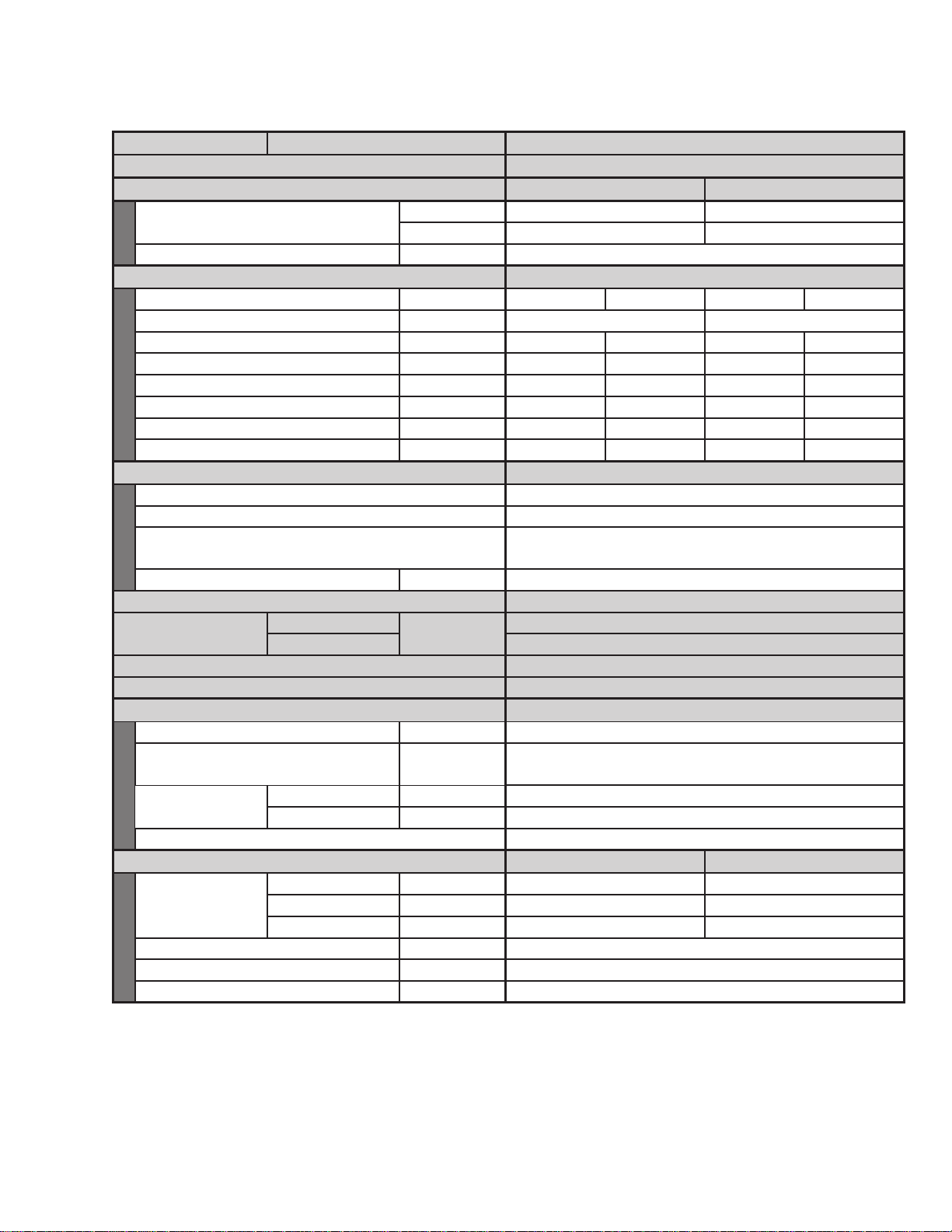
Outdoor Unit JCHX03652N, JCHXR03652N*
208 - 230 V / 1ø / 60 Hz
Cooling Heating
BTU / h 38,200 42,700
kW 11.2 12.5
Air circulation (Hi) CFM 3,530
1
ELECTRICAL RATINGS
Voltage rating V 208 230 208 230
Available voltage range V 187 - 253 187 - 253
Running amperes A 14.6 13.6 14.6 13.6
Max. running amperes * A 23.6 23.6
– –
Power input kW 2.76 2.76 2.88 2.88
Max. power input kW 4.85 4.85
– –
Power factor % 91 88 95 92
Max. starting amperes A Approx. 1 Approx. 1 Approx. 1 Approx. 1
FEATURES
Controls Microprocessor
Defrost control Reverse cycle, microprocessor control
Service function
Sensor temp. recall function
Past service warnings recall function
Refrigerant amount at shipment lbs. (kg) R410A - 7.7 (3.5)
Refrigerant control Electronic expansion valve
Operation sound (Hi)
Power level
Pressure level 51
dB-A
67
External finish Galvanized steel plate with powder paint
Color (Approximate value) Munsell code 1Y 8.5 /0.5
Refrigerant tubing
Limit of tubing length ft. (m) 492 (150)
Limit of elevation difference
between the 2 units
Refrigerant tube
diameter
Liquid tube in. (mm) 3/8 (9.52)
Gas tube in. (mm) 5/8 (15.88)
ft. (m)
Refrigerant tubing kit / Joint kit Optional
DIMENSIONS & WEIGHT
Height in. (mm) 48-7/16 (1230)
Unit dimensions
Net weight lbs. (kg) 229 (104)
Shipping weight lbs. (kg) 247 (112)
Shipping volume ft
Rated conditions
Cooling : Indoor air temperature 80°F DB / 67°F WB ; Outdoor air temperature 95°F DB
Heating : Indoor air temperature 70°F DB ; Outdoor air temperature 47°F DB / 43°F WB
* Full-load conditions at Indoor / Outdoor capacity ratio 100%
Cooling : Indoor air temperature 89°F DB / 73°F WB ; Outdoor air temperature 109°F DB / 78°F WB
1
*
Outdoor unit model name beginning with letters "JCHXR"
Refer to the Section 1 "Salt-Ait Damage Resistant Specications".
Width in. (mm) 37 (940)
Depth in. (mm) 13-13/32 (340)
3 (m3
) 19.8 (0.56)
Outdoor unit is higher than indoor unit : 164 (50)
Outdoor unit is lower than indoor unit : 131 (40)
Unit dimensions
Package dimensions
52-13/32 (1331)
40 (1016)
16-11/32 (415)
DATA SUBJECT TO CHANGE WITHOUT NOTICE
Page 18
Unit specications (B)
FORM 121.00-EG1
ISSUE DATE: 5/31/2012
JOHNSON CONTROLS
18
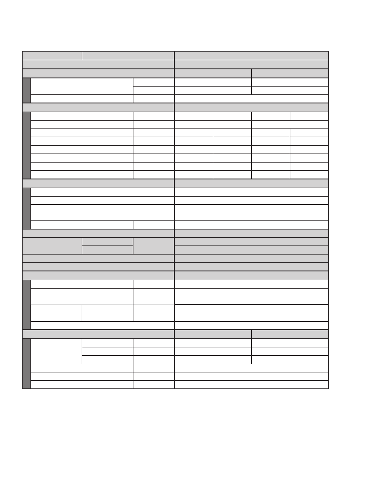
MODEL No.
POWER SOURCE
PERFORMANCE
Capacity
Outdoor Unit JCHX05252N, JCHXR05252N*
208 - 230 V / 1ø / 60 Hz
Cooling Heating
BTU / h 52,900 60,000
kW 15.5 17.6
Air circulation (Hi) CFM 3,530
1
ELECTRICAL RATINGS
Voltage rating V 208 230 208 230
Available voltage range V 187 - 253 187 - 253
Running amperes A 23.5 21.9 23.5 21.9
Max. running amperes * A 28.0 28.0
– –
Power input kW 4.57 4.57 4.58 4.58
Max. power input kW 5.72 5.72
– –
Power factor % 93 91 94 91
Max. starting amperes A Approx. 1 Approx. 1 Approx. 1 Approx. 1
FEATURES
Controls Microprocessor
Defrost control Reverse cycle, microprocessor control
Service function
Sensor temp. recall function
Past service warnings recall function
Refrigerant amount at shipment lbs. (kg) R410A - 7.7 (3.5)
Refrigerant control Electronic expansion valve
Operation sound (Hi)
Power level
Pressure level 52
dB-A
68
External finish Galvanized steel plate with powder paint
Color (Approximate value) Munsell code 1Y 8.5 /0.5
Refrigerant tubing
Limit of tubing length ft. (m) 492 (150)
Limit of elevation difference
between the 2 units
Refrigerant tube
diameter
Liquid tube in. (mm) 3/8 (9.52)
Gas tube in. (mm) 3/4 (19.05)
ft. (m)
Refrigerant tubing kit / Joint kit Optional
DIMENSIONS & WEIGHT
Height in. (mm) 48-7/16 (1230)
Unit dimensions
Net weight lbs. (kg) 229 (104)
Shipping weight lbs. (kg) 247 (112)
Shipping volume ft
Width in. (mm) 37 (940)
Depth in. (mm) 13-13/32 (340)
3 (m3
) 19.8 (0.56)
Outdoor unit is higher than indoor unit : 164 (50)
Outdoor unit is lower than indoor unit : 131 (40)
Unit dimensions
Package dimensions
52-13/32 (1331)
40 (1016)
16-11/32 (415)
DATA SUBJECT TO CHANGE WITHOUT NOTICE
Rated conditions
Cooling : Indoor air temperature 80°F DB / 67°F WB ; Outdoor air temperature 95°F DB
Heating : Indoor air temperature 70°F DB ; Outdoor air temperature 47°F DB / 43°F WB
* Full-load conditions at Indoor / Outdoor capacity ratio 100%
Cooling : Indoor air temperature 89°F DB / 73°F WB ; Outdoor air temperature 109°F DB / 78°F WB
1
*
Outdoor unit model name beginning with letters "JCHXR"
Refer to the Section 1 "Salt-Ait Damage Resistant Specications".
Page 19
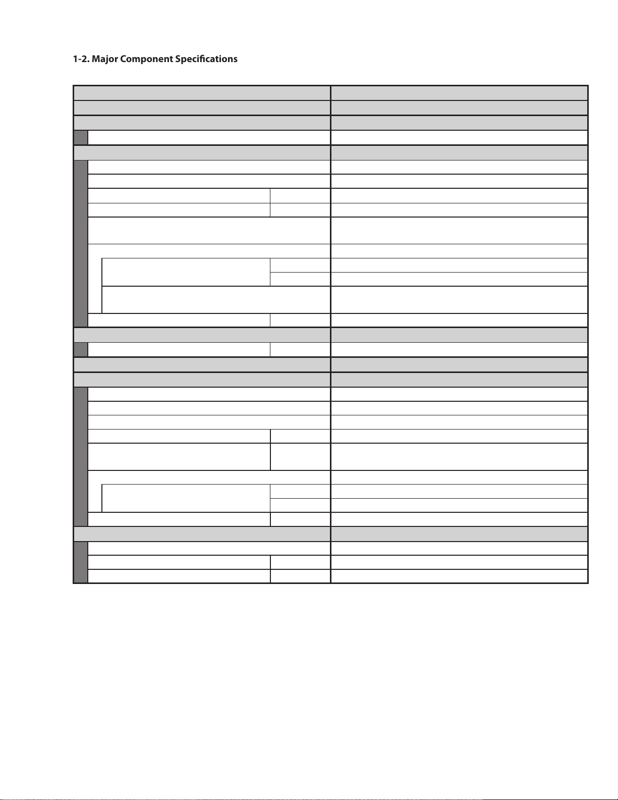
1-2. Major Component Specications
FORM 121.00-EG1
ISSUE DATE: 5/31/2012
19
JOHNSON CONTROLS
Specifications
Unit Specifications (1)
Outdoor unit (A)
MODEL No.
POWER SOURCE
Controller P.C.B Assembly
Control circuit fuse 250V, 5A
Compresser
Type Rotary (Hermetic)
Model ... Code No. C-9RVN273H0W ... 80867080
Motor rated output kW 2.1
Compressor Oil (ETHER FV68S) gal (cc) 0.50 (1,900)
Coil resistance
(Ambient temperature 77°F)
Safety devices
Overload protector
(Operating temperature)
Microprocessor safety devices
Crank case heater V, W 230, 30
Open°F (°C) 230 (110)
Close°F (°C) 203 (95)
Compressor discharge gas temperature control
JCHX03652N, JCHXR03652N*
208 - 230 V / 1ø / 60 Hz
CR-CHX03652
INV (Inverter)
V - U: 0.169, U-W: 0.169,
W-V: 0.169
Compressor current detection circuit
High pressure switch
Set pressure ON / OFF in. WG 456 / 551
Fan...(Number diameter / length in. (mm))
Propeller (1 ... ø18-7/64 (ø460)) ×2
Fan motor
Model No. DAJ12-95B61A, B-CR
Source DC340V / 3 phase
No. of pole 8
Nominal output W 90
Coil resistance
(Ambient temperature 68°F)
Safety device
Operating temperature
Run capacitor VAC, μF
Ω
Open°F (°C) 284 (140)
Close°F (°C)
RED - WHT : 30.5 WHT - BLK : 30.5
BLK - RED : 30.5
–
–
Heat exchanger
Coil Aluminum plate fin / Copper tube
Rows...fin pitch in. (mm) 3 ... 7/128 (1.4)
Face area ft
* Outdoor unit model name beginning with letters “JCHXR”
Refer to the Section 1 “2. Salt-Air Damage Resistant Specications”.
2 (m2
) 11.7 (1.08)
DATA SUBJECT TO CHANGE WITHOUT NOTICE
Page 20
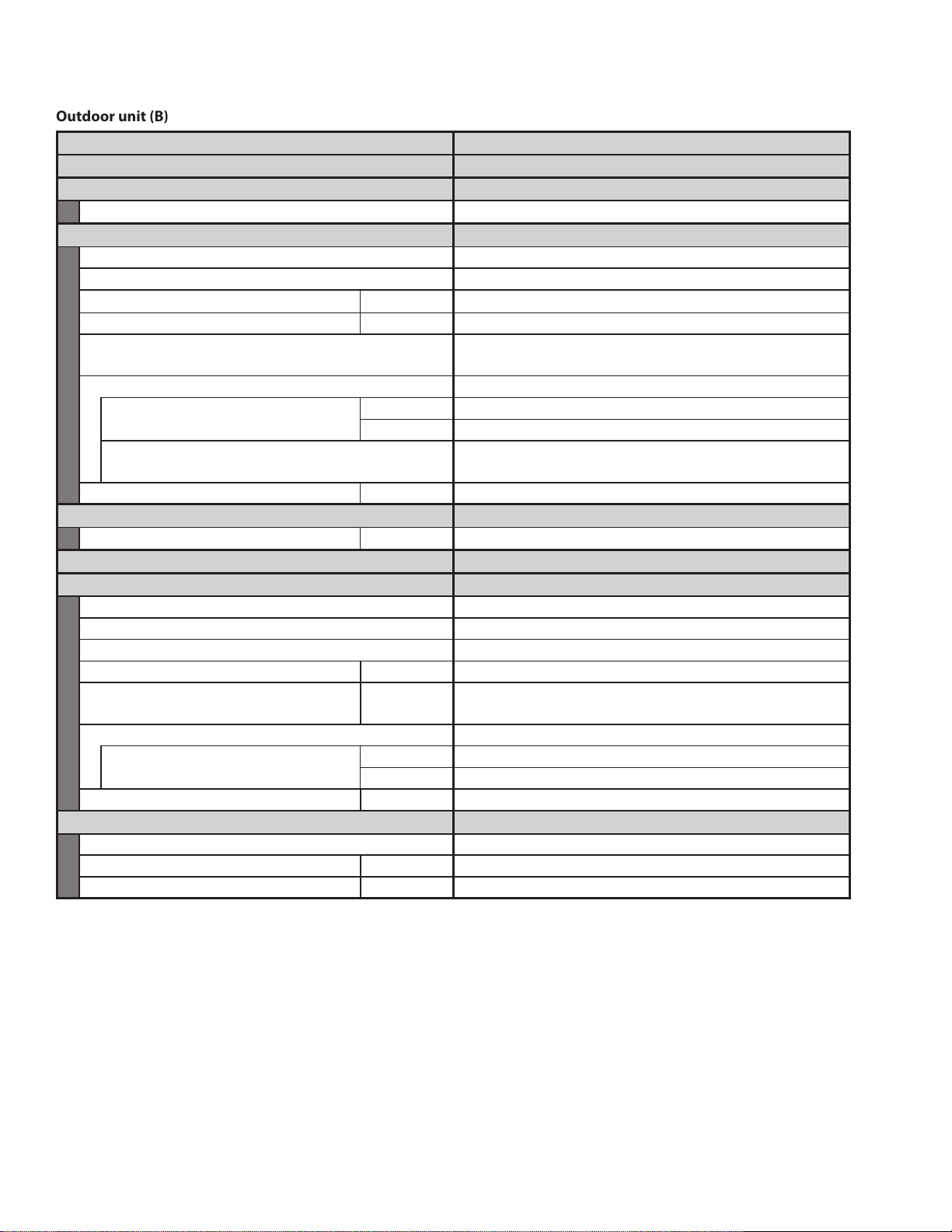
Outdoor unit (B)
FORM 121.00-EG1
ISSUE DATE: 5/31/2012
JOHNSON CONTROLS
20
Unit Specifications (2)
MODEL No.
POWER SOURCE
Controller P.C.B Assembly
Control circuit fuse 250V, 5A
Compresser
Type Rotary (Hermetic)
Model ... Code No. C-9RVN273H0W ... 80867080
Motor rated output kW 4.0
Compressor Oil (ETHER FV68S) gal (cc) 0.50 (1,900)
Coil resistance
(Ambient temperature 77°F)
Safety devices
Overload protector
(Operating temperature)
Microprocessor safety devices
Crank case heater V, W 230, 30
Open°F (°C) 230 (110)
Close°F (°C) 203 (95)
Compressor discharge gas temperature control
JCHX05252N, JCHXR05252N*
208 - 230 V / 1ø / 60 Hz
CR-CHX06052
INV (Inverter)
V - U: 0.169, U-W: 0.169,
W-V: 0.169
Compressor current detection circuit
High pressure switch
Set pressure ON / OFF in. WG 456 / 551
Fan...(Number diameter / length in. (mm))
Propeller (1 ... ø18-7/64 (ø460)) ×2
Fan motor
Model No. DAJ12-95B61A, B-CR
Source DC340V / 3 phase
No. of pole 8
Nominal output W 90
Coil resistance
(Ambient temperature 68°F)
Ω
RED - WHT : 30.5 WHT - BLK : 30.5
BLK - RED : 30.5
Safety device
Operating temperature
Run capacitor VAC, μF
Open°F (°C) 284 (140)
Close°F (°C)
–
–
Heat exchanger
Coil Aluminum plate fin / Copper tube
Rows...fin pitch in. (mm) 3 ... 7/128 (1.4)
Face area ft
2 (m2
) 11.7 (1.08)
* Outdoor unit model name beginning with letters “JCHXR”
Refer to the Section 1 “2. Salt-Air Damage Resistant Specications”.
DATA SUBJECT TO CHANGE WITHOUT NOTICE
Page 21
6-11/16
13-3/8
11-21/32
25/32
13/32
14-31/32
15-15/16
13/32
19/32
25-31/32
37
Air
discharge
8-5/8 5-29/32
1/2 1/2
1/21/2
2-
3/4
4-5/16
1
2
3
4
5
6
7
8
9
2-7/32
4-19/32
11-11/32
10-25/32
5/16
2-3/8
2-7/16
R1-3/16
R3/4
7
8
7
6
5
4
7
8
3-7/16
2-1/4
1-13/16
7
6
5
4
1-13/32
2-3/8
4-11/32
5-1/8
7-25/32
5-9/16
23-5/8
22-9/16
6-13/16
3-3/16
2-25/32
48-7/16
23/32
4-23/32
5-1/2
6-9/16
7-3/4
6-5/8
8-15/16
8-9/32
7-8/32
6-11/16
5-29/32
4-3/4
2-27/32
Air
intake
Air
discharge
7
8
2
3
9
3-29/32
25/32
6
5
2-3/8
7
4
Air intake
Installation anchoring hole (4-R6.5 or R1/4"), anchor bolt: M10 or 13/32''
Refrigerant tubing (liquid tube), flared connection ø3/8'' (ø9.52)
Refrigerant tubing (gas tube), flared connection ø5/8'' (ø15.88)
Refrigerant tubing port
Electrical wiring port ø1-3/8'' (ø35)
Electrical wiring port ø1-7/64'' (ø28)
Electrical wiring port ø55/64'' (ø22)
Electrical wiring port ø33/64'' (ø13)
Auxiliary connection tube ø5/8'' to ø3/4'' (ø15.88 to ø19.05) 6 hp only
2 x ø32 or ø1/4'' holes (holes for drain)
Of the 4 ø32 or ø1/4'' holes, use 1 of the 2 holes specified
for drain use to install the drain port.
Use rubber plugs to seal the remaining 3 holes.
1
For R410A only
Unit: inch
1-3. Dimensional Data
FORM 121.00-EG1
ISSUE DATE: 5/31/2012
21
JOHNSON CONTROLS
JCHX03652N, JCHXR03652N
JCHX05252N, JCHXR05252N
Page 22
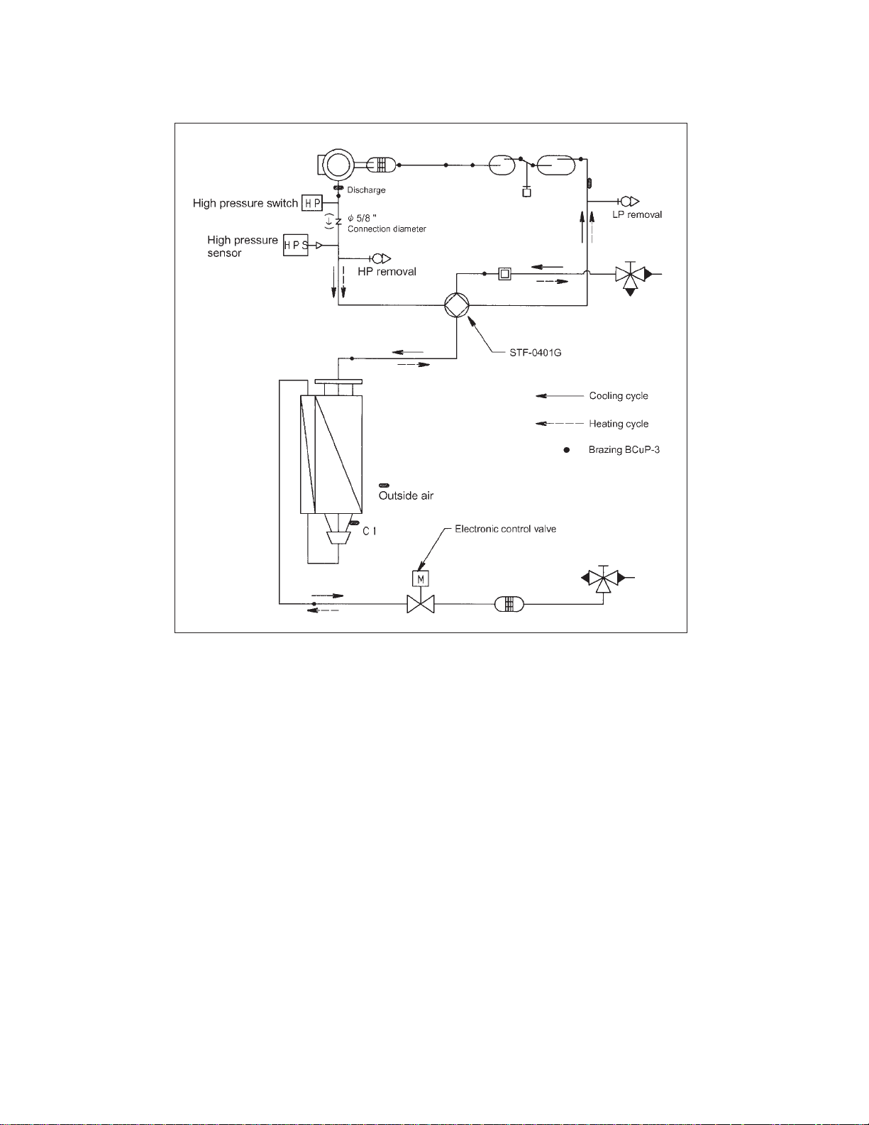
1-4. Refrigerant Flow Diagram
FORM 121.00-EG1
ISSUE DATE: 5/31/2012
JOHNSON CONTROLS
22
JCHX03652N
JCHXR03652N
JCHX05252N
JCHXR05252N
Suction
Page 23
1-5. Sound Data
NOTE
Model
Sound Power
Level
Condition
Sound Power Level (dB)
Frequency at center of sound pressure band (Hz)
JCHX03652N, JCHXR03652N
67 dB (A)
Cooling
10
20
30
40
50
60
70
80
NC – 70
NC – 60
NC – 50
NC – 40
NC – 30
NC – 20
63 125 250 500 1000 2000 4000 8000
90
1. dBA = A – weighted sound power level (A – scale according to IEC)
2. Reference acoustic intensity 0 dB = 10
–13
W/ft
2
FORM 121.00-EG1
ISSUE DATE: 5/31/2012
23
JOHNSON CONTROLS
JCHDZ07263N
JCHDZR07263N
JCHDZ09663N
JCHDZR09663N
(1) Sound Power Level
JCHX03652N, JCHXR03652N
Page 24
NOTE
Model
SoundPower
Level
Condition
SoundPowerLevel(dB)
JCHX05252N,JCHXR05252N
68dB(A)
Cooling
10
20
30
40
50
60
70
80
NC‒70
NC‒60
NC‒50
NC‒40
NC‒30
NC‒20
63 125 250 500 1000 2000 4000 8000
90
Frequencyatcenterofsoundpressureband(Hz)
1.dBA=A‒weightedsoundpowerlevel(A‒scaleaccordingtoIEC)
2.Referenceacousticintensity0dB=10
‒13
W/ft
2
JCHX05252N, JCHXR05252N
FORM 121.00-EG1
ISSUE DATE: 5/31/2012
JOHNSON CONTROLS
24
Page 25
Octave Band Level (dB)*
* 0 dB = 0.0002 µbar
Frequency at center of sound pressure band (Hz)
Front
Quiet Mode
10
20
30
40
50
60
70
80
NC – 70
NC – 60
NC – 50
NC – 40
NC – 30
NC – 20
63
Overall
125 250 500 1000 2000 4000 8000
90
Approximate
minimum audible
limit for continuous
noise
(2) Sound Pressure Level
FORM 121.00-EG1
ISSUE DATE: 5/31/2012
25
JOHNSON CONTROLS
JCHDZ07263N, JCHDZR07263N
JCHDZ09663N, JCHDZR09663N
JCHX0352N, JCHXR03652N
Model
Sound Pressure Level
Cooling
Condition
JCHX03652N, JCHXR03652N
Front 51 dB (A)
Quiet Mode 48 dB (A)
3.3 ft. in front at height of 4.9 ft.
Page 26
Model
Sound Pressure Level
Cooling
Condition
Octave Band Level (dB)*
* 0 dB = 0.0002 µbar
Frequency at center of sound pressure band (Hz)
JCHX05252N, JCHXR05252N
Front 52 dB (A)
Quiet Mode 49 dB (A)
Front
Quiet Mode
3.3 ft. in front at height of 4.9 ft.
10
20
30
40
50
60
70
80
NC – 70
NC – 60
NC – 50
NC – 40
NC – 30
NC – 20
63 125 250 500 1000 2000 4000 8000
90
Approximate
minimum audible
limit for continuous
noise
Overall
JCHX05252N, JCHXR05252N
FORM 121.00-EG1
ISSUE DATE: 5/31/2012
JOHNSON CONTROLS
26
Page 27
MODEL No.
FORM 121.00-EG1
ISSUE DATE: 5/31/2012
27
JOHNSON CONTROLS
3. Indoor Unit Dimensions and Specifications
4-Way Air Discharge Ceiling Semi-Concealed, Standard and Mini (JX, JXM Types)
Unit specifications (A)
POWER SOURCE
PERFORMANCE
Capacity
Air circulation (Hi / Me / Lo) CFM 550 / 495 / 450
Moisture removal (High) Pints / h 4.65 –
ELECTRICAL RATINGS
Voltage rating V 208 230 208 230
Available voltage range V 187 - 253 187 - 253
Running amperes A 0.19 0.22 0.21 0.21
Power input W 26 29 19 20
Power factor % 66 57 43 41
Max. starting amperes A 1111
FEATURES
Controls Microprocessor
Fan speeds 3 and Automatic control
Air filter Washable, easy access, long life (2,500 hr)
Refrigerant control Electronic expansion valve
Operation sound (
Refrigerant tubing connections Flare type
Refrigerant tube
diameter
Drain connection 25 A, OD 1-1/4"
Drain pump Max. head 2.1 ft. above drain connection
Panel Optional (JPNR-XH3652N)
Remote controller Optional (JRCS-TM80BGN, JRCS-SH80AABWLN)
Refrigerant tubing kit / Accessories Optional / –
Color (Approximate value) Munsell 2.5GY 9.0 / 0.5, RAL 9001-GL (resemblant color)
DIMENSIONS & WEIGHT
Unit dimensions
Net weight lbs. (kg) 56 (25.5) – –
Shipping weight lbs. (kg) – 53 (24) 16 (7)
Shipping volume ft
Hi / Me / Lo
Liquid tube in. (mm) 1 / 4 (6.35)
Gas tube in. (mm) 1 / 2 (12.7)
Height in. (mm) 11-15 / 32 (291)
Width in. (mm) 37-13 / 32 (950)
Depth in. (mm) 37-13 / 32 (950)
Indoor Unit JXHX1252N
208 - 230 V / 1ø / 60 Hz
Cooling Heating
BTU / h 12,000 14,000
kW 3.6 4.2
) dB-A 31 / 29 / 27
Indoor unit (including panel)
11-5 / 32 (283)
35-1 / 8 (892)
35-5 / 8 (905) 38-31 / 32 (990)
3 (m3
) – 8.1 (0.228) 3.8 (0.104)
Package
Body Panel
4-3 / 32 (104)
39-11 / 16 (1008)
1
2
3
4
5
6
Rated conditions
Cooling : Indoor air temperature 80°F DB / 67°F WB ; Outdoor air temperature 95°F DB
Heating : Indoor air temperature 70°F DB ; Outdoor air temperature 47°F DB / 43°F WB
7
8
Page 28

2
FORM 121.00-EG1
ISSUE DATE: 5/31/2012
JOHNSON CONTROLS
28
4-Way Air Discharge Ceiling Semi-Concealed, Standard and Mini (JX, JXM Types)
Unit specifications (B)
3
4
5
MODEL No.
POWER SOURCE
PERFORMANCE
Capacity
Air circulation (Hi / Me / Lo) CFM 565 / 495 / 450
Moisture removal (High) Pints / h 4.65 –
ELECTRICAL RATINGS
Voltage rating V 208 230 208 230
Available voltage range V 187 - 253 187 - 253
Running amperes A 0.23 0.26 0.23 0.22
Power input W 30 33 25 25
Power factor % 63 55 52 49
Max. starting amperes A 1111
FEATURES
Controls Microprocessor
Fan speeds 3 and Automatic control
Air filter Washable, easy access, long life (2,500 hr)
Refrigerant control Electronic expansion valve
Operation sound (
Refrigerant tubing connections Flare type
Refrigerant tube diameter
Drain connection 25 A, OD 1-1/4"
Drain pump Max. head 2.1 ft. above drain connection
Panel Optional (JPNR-XH3652N)
Remote controller Optional (JRCS-TM80BGN, JRCS-SH80AABWLN)
Refrigerant tubing kit / Accessories Optional / –
Color (Approximate value) Munsell 2.5GY 9.0 / 0.5, RAL 9001-GL (resemblant color)
DIMENSIONS & WEIGHT
Unit dimensions
Net weight lbs. (kg) 56 (25.5) – –
Shipping weight lbs. (kg) – 53 (24) 16 (7)
Shipping volume ft
Hi / Me / Lo
Liquid tube in. (mm) 1 / 4 (6.35)
Gas tube in. (mm) 1 / 2 (12.7)
Height in. (mm) 11-15 / 32 (291)
Width in. (mm) 37-13 / 32 (950)
Depth in. (mm) 37-13 / 32 (950)
Indoor Unit JXHX1852N
208 - 230 V / 1ø / 60 Hz
Cooling Heating
BTU / h 19,000 21,000
kW 5.6 6.3
) dB-A 31 / 29 / 27
Indoor unit (including panel)
11-5 / 32 (283)
35-1 / 8 (892)
35-5 / 8 (905) 38-31 / 32 (990)
3 (m3
) – 8.1 (0.228) 3.8 (0.104)
Package
Body Panel
4-3 / 32 (104)
39-11 / 16 (1008)
6
7
8
Rated conditions
Cooling : Indoor air temperature 80°F DB / 67°F WB ; Outdoor air temperature 95°F DB
Heating : Indoor air temperature 70°F DB ; Outdoor air temperature 47°F DB / 43°F WB
Page 29

MODEL No.
FORM 121.00-EG1
ISSUE DATE: 5/31/2012
29
JOHNSON CONTROLS
4-Way Air Discharge Ceiling Semi-Concealed, Standard and Mini (JX, JXM Types)
Unit specifications (C)
POWER SOURCE
PERFORMANCE
Capacity
Air circulation (Hi / Me / Lo) CFM 705 / 565 / 495
Moisture removal (High) Pints / h 5.92 –
ELECTRICAL RATINGS
Voltage rating V 208 230 208 230
Available voltage range V 187 - 253 187 - 253
Running amperes A 0.29 0.26 0.30 0.31
Power input W 38 40 33 33
Power factor % 63 67 39 46
Max. starting amperes A 1111
FEATURES
Controls Microprocessor
Fan speeds 3 and Automatic control
Air filter Washable, easy access, long life (2,500 hr)
Refrigerant control Electronic expansion valve
Operation sound (
Refrigerant tubing connections Flare type
Refrigerant tube diameter
Drain connection 25 A, OD 1-1/4"
Drain pump Max. head 2.1 ft. above drain connection
Panel Optional (JPNR-XH3652N)
Remote controller Optional (JRCS-TM80BGN, JRCS-SH80AABWLN)
Refrigerant tubing kit / Accessories Optional / –
Color (Approximate value) Munsell 2.5GY 9.0 / 0.5, RAL 9001-GL (resemblant color)
DIMENSIONS & WEIGHT
Unit dimensions
Net weight lbs. (kg) 58 (26.5) – –
Shipping weight lbs. (kg) – 53 (24) 16 (7)
Shipping volume ft
Hi / Me / Lo
Liquid tube in. (mm) 3 / 8 (9.52)
Gas tube in. (mm) 5 / 8 (15.88)
Height in. (mm) 11-15 / 32 (291)
Width in. (mm) 37-13 / 32 (950)
Depth in. (mm) 37-13 / 32 (950)
Indoor Unit JXHX2452N
208 - 230 V / 1ø / 60 Hz
Cooling Heating
BTU / h 25,000 27,000
kW 7.3 8.0
) dB-A 34 / 31 / 28
Indoor unit (including panel)
11-5 / 32 (283)
35-1 / 8 (892)
35-5 / 8 (905) 38-31 / 32 (990)
3 (m3
) – 8.1 (0.228) 3.8 (0.104)
Package
Body Panel
4-3 / 32 (104)
39-11 / 16 (1008)
1
2
3
5
Rated conditions
Cooling : Indoor air temperature 80°F DB / 67°F WB ; Outdoor air temperature 95°F DB
Heating : Indoor air temperature 70°F DB ; Outdoor air temperature 47°F DB / 43°F WB
6
7
8
Page 30
2
FORM 121.00-EG1
ISSUE DATE: 5/31/2012
JOHNSON CONTROLS
30
4-Way Air Discharge Ceiling Semi-Concealed, Standard and Mini (JX, JXM Types)
Unit specifications (D)
3
4
5
MODEL No.
POWER SOURCE
PERFORMANCE
Capacity
Air circulation (Hi / Me / Lo) CFM 990 / 810 / 740
Moisture removal (High) Pints / h 8.24 –
ELECTRICAL RATINGS
Voltage rating V 208 230 208 230
Available voltage range V 187 - 253 187 - 253
Running amperes A 0.51 0.46 0.54 0.49
Power input W 74 79 76 76
Power factor % 70 75 68 67
Max. starting amperes A 1111
FEATURES
Controls Microprocessor
Fan speeds 3 and Automatic control
Air filter Washable, easy access, long life (2,500 hr)
Refrigerant control Electronic expansion valve
Operation sound (
Refrigerant tubing connections Flare type
Refrigerant tube diameter
Drain connection 25 A, OD 1-1/4"
Drain pump Max. head 2.1 ft. above drain connection
Panel Optional (JPNR-XH3652N)
Remote controller Optional (JRCS-TM80BGN, JRCS-SH80AABWLN)
Refrigerant tubing kit / Accessories Optional / –
Color (Approximate value) Munsell 2.5GY 9.0 / 0.5, RAL 9001-GL (resemblant color)
DIMENSIONS & WEIGHT
Unit dimensions
Net weight lbs. (kg) 58 (26.5) – –
Shipping weight lbs. (kg) – 66 (30) 16 (7)
Shipping volume ft
Hi / Me / Lo
Liquid tube in. (mm) 3 / 8 (9.52)
Gas tube in. (mm) 5 / 8 (15.88)
Height in. (mm) 13-15 / 16 (354) 13-5 / 8 (346) 4-3 / 32 (104)
Width in. (mm) 37-13 / 32 (950) 35-1 / 8 (892)
Depth in. (mm) 37-13 / 32 (950) 35-5 / 8 (905)
Indoor Unit JXHX3652N
208 - 230 V / 1ø / 60 Hz
Cooling Heating
BTU / h 36,000 39,000
kW 10.6 11.4
) dB-A 39 / 36 / 33
Indoor unit (including panel)
3 (m3
) – 9.9 (0.279) 3.8 (0.104)
Package
Body Panel
39-11 / 16 (1008)
38-31 / 32 (990)
6
7
8
Rated conditions
Cooling : Indoor air temperature 80°F DB / 67°F WB ; Outdoor air temperature 95°F DB
Heating : Indoor air temperature 70°F DB ; Outdoor air temperature 47°F DB / 43°F WB
Page 31

MODEL No.
FORM 121.00-EG1
ISSUE DATE: 5/31/2012
31
JOHNSON CONTROLS
4-Way Air Discharge Ceiling Semi-Concealed, Standard and Mini (JX, JXM Types)
Unit specifications (E)
SOURCE
PERFORMANCE
Capacity
Air circulation (Hi / Me / Lo) CFM 320 / 280 / 250
Moisture removal (High) Pints / h 2.3 –
ELECTRICAL RATINGS
Voltage rating V 208 230 208 230
Available voltage range V 187 - 253 187 - 253
Running amperes A 0.22 0.20 0.19 0.17
Power input W 38 43 30 35
Power factor % 83 93 76 90
Max. starting amperes A 1111
FEATURES
Controls Microprocessor
Timer ON / OFF Timer (Max. 72 hr)
Fan speeds 3 and Automatic control
Air filter Washable, easy access, long life (2,500 hr)
Refrigerant control Electronic expansion valve
Operation sound (
Refrigerant tubing connections Flare type
Refrigerant tube diameter
Drain connection OD 1-1/4"
Drain pump Max. head 2.1 ft. above drain connection
Panel Optional (JPNR-XMH1852N)
Remote controller Optional (JRCS-TM80BGN, JRCS-XM18AABWLN)
Refrigerant tubing kit / Accessories Optional / –
Color (Approximate value) Munsell 2.5GY 9.0 / 0.5, RAL 9001-GL (resemblant color)
DIMENSIONS & WEIGHT
Unit dimensions
Net weight lbs. (kg) 40.6 (18.4) – –
Shipping weight lbs. (kg) – 41.9 (19) 7.7 (3.5)
Shipping volume ft
Hi / Me / Lo
Liquid tube in. (mm) 1 / 4 (6.35)
Gas tube in. (mm) 1 / 2 (12.7)
Height in. (mm) 12-3 / 8 (313) 11-3 / 8 (290) 4-1 / 8 (105)
Width in. (mm) 24-5 / 8 (625) 28-1 / 8 (714) 26-1 / 4 (665)
Depth in. (mm) 24-5 / 8 (625) 24-3 / 4 (630) 26-5 / 8 (678)
Indoor Unit JXMHX1252N
208 - 230 V / 1ø / 60 Hz
Cooling Heating
BTU / h 12,000 14,000
kW 3.6 4.2
) dB-A 31 / 29 / 27
Indoor unit (including panel)
3 (m3
) – 4.6 (0.13) 1.7 (0.047)
Package
Body Panel
1
2
3
4
5
6
Rated conditions
Cooling : Indoor air temperature 80°F DB / 67°F WB ; Outdoor air temperature 95°F DB
Heating : Indoor air temperature 70°F DB ; Outdoor air temperature 47°F DB / 43°F WB
7
8
Page 32

2
FORM 121.00-EG1
ISSUE DATE: 5/31/2012
JOHNSON CONTROLS
32
4-Way Air Discharge Ceiling Semi-Concealed, Standard and Mini (JX, JXM Types)
Unit specifications (F)
3
4
5
6
MODEL No.
SOURCE
PERFORMANCE
Capacity
Air circulation (Hi / Me / Lo) CFM 440 / 370 / 320
Moisture removal (High) Pints / h 4.0 –
ELECTRICAL RATINGS
Voltage rating V 208 230 208 230
Available voltage range V 187 - 253 187 - 253
Running amperes A 0.32 0.30 0.30 0.27
Power input W 52 56 48 47
Power factor % 78 81 77 76
Max. starting amperes A 1111
FEATURES
Controls Microprocessor
Timer ON / OFF Timer (Max. 72 hr)
Fan speeds 3 and Automatic control
Air filter Washable, easy access, long life (2,500 hr)
Refrigerant control Electronic expansion valve
Operation sound (
Refrigerant tubing connections Flare type
Refrigerant tube diameter
Drain connection OD 1-1/4"
Drain pump Max. head 2.1 ft. above drain connection
Panel Optional (JPNR-XMH1852N)
Remote controller Optional (JRCS-TM80BGN, JRCS-XM18AABWLN)
Refrigerant tubing kit / Accessories Optional / –
Color (Approximate value) Munsell 2.5GY 9.0 / 0.5, RAL 9001-GL (resemblant color)
DIMENSIONS & WEIGHT
Unit dimensions
Net weight lbs. (kg) 40.6 (18.4) – –
Shipping weight lbs. (kg) – 41.9 (19) 7.7 (3.5)
Shipping volume ft
Hi / Me / Lo
Liquid tube in. (mm) 1 / 4 (6.35)
Gas tube in. (mm) 1 / 2 (12.7)
Height in. (mm) 12-3 / 8 (313) 11-3 / 8 (290) 4-1 / 8 (105)
Width in. (mm) 24-5 / 8 (625) 28-1 / 8 (714) 26-1 / 4 (665)
Depth in. (mm) 24-5 / 8 (625) 24-3 / 4 (630) 26-5 / 8 (678)
Indoor Unit JXMHX1852N
208 - 230 V / 1ø / 60 Hz
Cooling Heating
BTU / h 19,000 21,000
kW 5.6 6.3
) dB-A 41 / 37 / 33
Indoor unit (including panel)
3 (m3
) – 4.6 (0.13) 1.7 (0.047)
Package
Body Panel
7
8
Rated conditions
Cooling : Indoor air temperature 80°F DB / 67°F WB ; Outdoor air temperature 95°F DB
Heating : Indoor air temperature 70°F DB ; Outdoor air temperature 47°F DB / 43°F WB
Page 33

MODEL No.
FORM 121.00-EG1
ISSUE DATE: 5/31/2012
33
JOHNSON CONTROLS
4-Way Air Discharge Ceiling Semi-Concealed, Standard and Mini (JX, JXM Types)
Major Component Specifications
Indoor unit (A)
Power source
Controller P.C.B. Ass'y
Fan...(Number diameter / length in. (mm))
Fan motor
Model...Nominal output W DK8-53B280HB...50W
Power source 280 VDC
No. of pole...r.p.m. (230V, High) rpm 8P...360
Coil resistance
(Ambient temperature 68°F)
Run capacitor VAC, μF –
Safety device
Operating temperature Open °F (°C)
Electronic expansion valve
Coil UKV-U030E
Coil resistance (at 68°F)
Valve body UKV-18D31
Heat exchanger
Coil Aluminum plate fin / Copper tube
Rows...fin pitch in. (mm) 2...3/64 (1.25)
Face area ft
Panel
Model No. JPNR-XH3652N
Auto louver motor MP24ZN
Coil resistance (at 77°F)
Drain pump
Rated
Total head & capacity
(above drain connection)
2 (m2
) 3.88 (0.360)
V, Hz, W
ft. (mm), gal/
min (cc/min)
ORG – GRY : 46 YEL – GRY : 46
RED – GRY : 46 BLK – GRY : 46
CR-UMHX0762 (Microprocessor)
JXHX1252N
208 - 230 V / 1ø / 60 Hz
Turbo (1...ø18-7/64 (ø460))
RED – WHT : 87.0
WHT – BLU : 87.0
BLU – RED : 87.0
fuse
+4
+2
(141
285
–5
380 ± 7% / phase
PLD-12230ST
AC230V, 60Hz, 10.8W
2.1 (640), 0.11 (400)
)
–3
1
2
3
4
5
6
7
8
Page 34

2
FORM 121.00-EG1
ISSUE DATE: 5/31/2012
JOHNSON CONTROLS
34
4-Way Air Discharge Ceiling Semi-Concealed, Standard and Mini (JX, JXM Types)
Indoor unit (B)
3
4
5
MODEL No.
Power source
Controller P.C.B. Ass'y
Fan...(Number diameter / length in. (mm))
CR-UMHX0762 (Microprocessor)
Turbo (1...ø18-7/64 (ø460))
JXHX1852N
208 - 230 V / 1ø / 60 Hz
Fan motor
Model...Nominal output W DK8-53B280HB...50W
Power source 280 VDC
No. of pole...r.p.m. (230V, High) rpm 8P...390
Coil resistance
(Ambient temperature 68°F)
Run capacitor VAC, μF –
Safety device
Operating temperature Open °F (°C)
RED – WHT : 87.0
WHT – BLU : 87.0
BLU – RED : 87.0
fuse
+4
–5
(141
+2
)
–3
285
Electronic expansion valve
Coil UKV-U030E
Coil resistance (at 68°F)
Valve body UKV-25D32
ORG – GRY : 46 YEL – GRY : 46
RED – GRY : 46 BLK – GRY : 46
Heat exchanger
Coil Aluminum plate fin / Copper tube
Rows...fin pitch in. (mm) 2...3/64 (1.25)
2 (m2
Face area ft
) 3.88 (0.360)
Panel
Model No. JPNR-XH3652N
Auto louver motor MP24ZN
Coil resistance (at 77°F)
Drain pump
Rated
Total head & capacity
(above drain connection)
V, Hz, W
ft. (mm), gal/
min (cc/min)
380 ± 7% / phase
PLD-12230ST
AC230V, 60Hz, 10.8W
2.1 (640), 0.11 (400)
6
7
8
Page 35

MODEL No.
FORM 121.00-EG1
ISSUE DATE: 5/31/2012
35
JOHNSON CONTROLS
4-Way Air Discharge Ceiling Semi-Concealed, Standard and Mini (JX, JXM Types)
Indoor unit (C)
Power source
Controller P.C.B. Ass'y
Fan...(Number diameter / length in. (mm))
Fan motor
Model...Nominal output W DK8-53B280HB...50W
Power source 280 VDC
No. of pole...r.p.m. (230V, High) rpm 8P...440
Coil resistance
(Ambient temperature 68°F)
Run capacitor VAC, μF –
Safety device
Operating temperature Open °F (°C)
Electronic expansion valve
Coil UKV-U030E
Coil resistance (at 68°F)
Valve body UKV-25D32
Heat exchanger
Coil Aluminum plate fin / Copper tube
Rows...fin pitch in. (mm) 2...3/64 (1.25)
Face area ft
Panel
Model No. JPNR-XH3652N
Auto louver motor MP24ZN
Coil resistance (at 77°F)
Drain pump
Rated
Total head & capacity
(above drain connection)
2 (m2
) 4.36 (0.405)
V, Hz, W
ft. (mm), gal/
min (cc/min)
ORG – GRY : 46 YEL – GRY : 46
RED – GRY : 46 BLK – GRY : 46
CR-UMHX0762 (Microprocessor)
Turbo (1...ø18-7/64 (ø460))
RED – WHT : 87.0
WHT – BLU : 87.0
BLU – RED : 87.0
JXHX2452N
208 - 230 V / 1ø / 60 Hz
fuse
+4
–5
(141
+2
)
–3
285
380 ± 7% / phase
PLD-12230ST
AC230V, 60Hz, 10.8W
2.1 (640), 0.11 (400)
1
2
3
4
5
6
7
8
Page 36

2
FORM 121.00-EG1
ISSUE DATE: 5/31/2012
JOHNSON CONTROLS
36
4-Way Air Discharge Ceiling Semi-Concealed, Standard and Mini (JX, JXM Types)
Indoor unit (D)
3
4
5
MODEL No.
Power source
Controller P.C.B. Ass'y
Fan...(Number diameter / length in. (mm))
CR-UMHX0762 (Microprocessor)
Turbo (1...ø18-7/64 (ø460))
JXHX3652N
208 - 230 V / 1ø / 60 Hz
Fan motor
Model...Nominal output W DK8-93C280HB...90W
Power source 280 VDC
No. of pole...r.p.m. (230V, High) rpm 8P...540
Coil resistance
(Ambient temperature 68°F)
Run capacitor VAC, μF –
Safety device
Operating temperature Open °F (°C)
RED – WHT : 43.0
WHT – BLU : 43.0
BLU – RED : 43.0
fuse
+4
–5
(141
+2
)
–3
285
Electronic expansion valve
Coil UKV-U030E
Coil resistance (at 68°F)
Valve body UKV-30D33
ORG – GRY : 46 YEL – GRY : 46
RED – GRY : 46 BLK – GRY : 46
Heat exchanger
Coil Aluminum plate fin / Copper tube
Rows...fin pitch in. (mm) 2...3/64 (1.25)
2 (m2
Face area ft
) 6.29 (0.584)
Panel
Model No. JPNR-XH3652N
Auto louver motor MP24ZN
Coil resistance (at 77°F)
Drain pump
Rated
Total head & capacity
(above drain connection)
V, Hz, W
ft. (mm), gal/
min (cc/min)
380 ± 7% / phase
PLD-12230ST
AC230V, 60Hz, 10.8W
2.1 (640), 0.11 (400)
6
7
8
Page 37

MODEL No.
FORM 121.00-EG1
ISSUE DATE: 5/31/2012
37
JOHNSON CONTROLS
4-Way Air Discharge Ceiling Semi-Concealed, Standard and Mini (JX, JXM Types)
Indoor unit (E)
Source
Controller P.C.B. Ass'y
Fan...(Number diameter)
Fan motor
Model...Nominal output W SIC-72FV-D866-1B...20W
Source 340 V (DC)
No. of pole...r.p.m. (230V, High) rpm 8P...750
in. (mm) Turbo (1...ø12-5/8 (ø322), L5-3/4 (L147))
CR-XMHX1252 (Microprocessor), POW-XM075XH
JXMHX1252N
208 - 230 V / 1ø / 60 Hz
Coil resistance
(Ambient temperature 68°F)
Run capacitor VAC, μF –
Safety device
Operating temperature Open °F (°C)
Electronic expansion valve
Coil UKV-A054
Coil resistance (at 68°F)
Valve body UKV-18D31
Heat exchanger
Coil Aluminum plate fin / Copper tube
Rows...fin pitch in. (mm) 2...1/16 (1.4)
Face area ft
Panel
Model No. JPNR-XMH1852N
Auto louver motor MP24ZN-12V
Coil resistance (at 77°F)
Drain pump
Rated
Total head & capacity
(above drain connection)
2 (m2
) 2.91 (0.27)
V, Hz, W
ft. (mm), gal/
min (cc/min)
–
fuse
+4
–5
(141
+2
)
–3
285
ORG – GRY : 46 YEL – GRY : 46
RED – GRY : 46 BLK – GRY : 46
380 ± 7% / phase
PLD-12230ST-2
AC230V, 60Hz, 10.8W
2.1 (640), 0.11 (400)
1
2
3
4
5
6
7
8
Page 38

MODEL No.
FORM 121.00-EG1
ISSUE DATE: 5/31/2012
JOHNSON CONTROLS
38
4-Way Air Discharge Ceiling Semi-Concealed, Standard and Mini (JX, JXM Types)
Indoor unit (F)
Source
Controller P.C.B. Ass'y
Fan...(Number diameter)
CR-XMHX1252 (Microprocessor), POW-XM075XH
in. (mm) Turbo (1...ø12-5/8 (ø322), L5-3/4 (L147))
JXMHX1852N
208 - 230 V / 1ø / 60 Hz
Fan motor
Model...Nominal output W SIC-72FV-D866-1B...20W
Source 340 V (DC)
No. of pole...r.p.m. (230V, High) rpm 8P...750
2
3
4
5
Coil resistance
(Ambient temperature 68°F)
Run capacitor VAC, μF –
Safety device
Operating temperature Open °F (°C)
285
fuse
+4
–5
–
(141
+2
)
–3
Electronic expansion valve
Coil UKV-A054
Coil resistance (at 68°F)
Valve body UKV-25D32
ORG – GRY : 46 YEL – GRY : 46
RED – GRY : 46 BLK – GRY : 46
Heat exchanger
Coil Aluminum plate fin / Copper tube
Rows...fin pitch in. (mm) 2...1/16 (1.4)
2 (m2
Face area ft
) 2.91 (0.27)
Panel
Model No. JPNR-XMH1852N
Auto louver motor MP24ZN-12V
Coil resistance (at 77°F)
Drain pump
Rated
Total head & capacity
(above drain connection)
V, Hz, W
ft. (mm), gal/
min (cc/min)
380 ± 7% / phase
PLD-12230ST-2
AC230V, 60Hz, 10.8W
2.1 (640), 0.11 (400)
6
7
8
Page 39

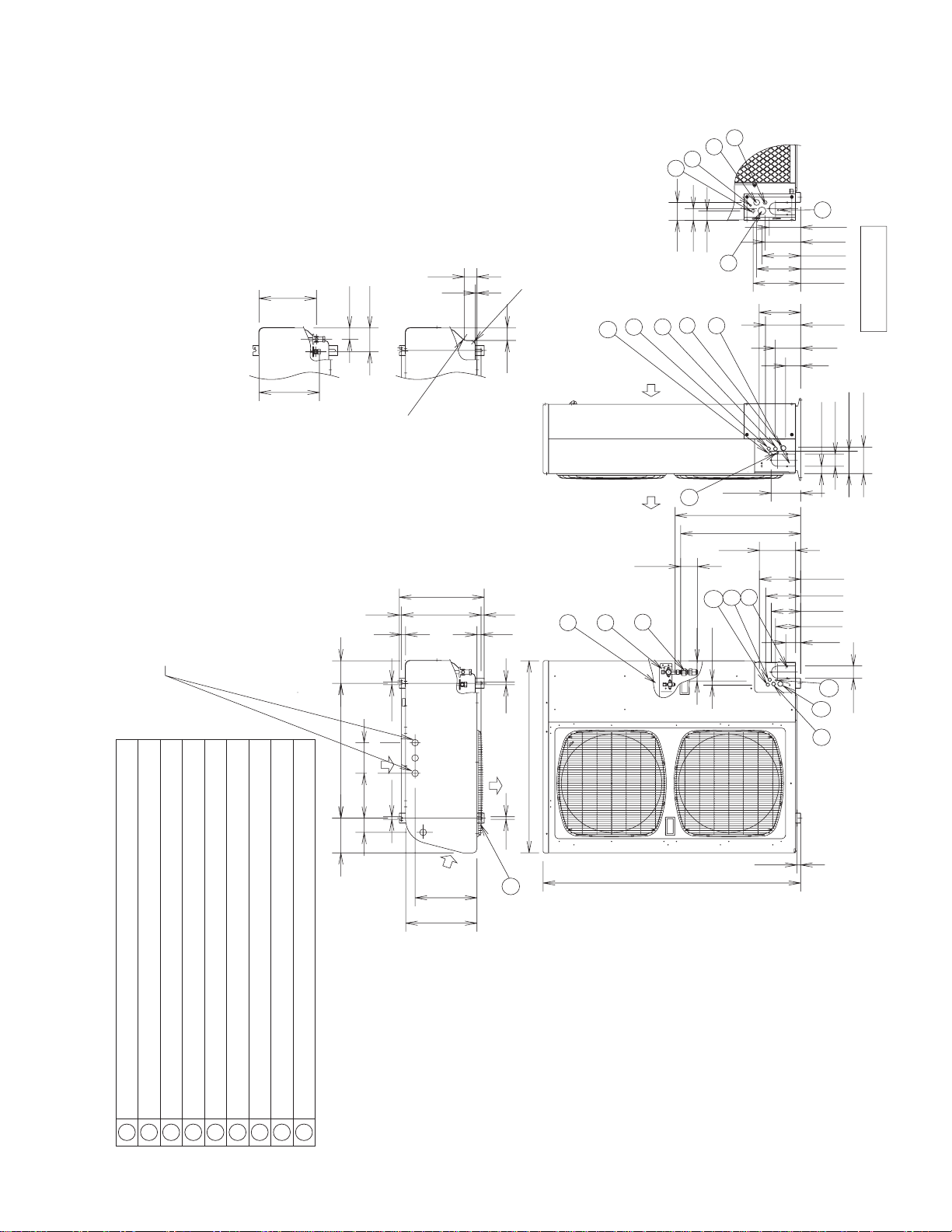
Dimensional Data
FORM 121.00-EG1
ISSUE DATE: 5/31/2012
39
JOHNSON CONTROLS
4-Way Air Discharge Ceiling Semi-Concealed, Standard and Mini (JX, JXM Types)
Dimensional Data
Indoor unit: JXHX1252N/JXHX1852N/JXHX2452N
1-3/16
3-13/16
3-15/32
3-15/32
33-55/64 – 35-53/64
Ceiling opening dimensions
28-15/32
Suspension bolt pitch
Ceiling opening
dimensions
X
31-7/64 Suspension bolt pitch
33-55/64 – 35-53/64
Center of
4-23/32
panel
18-57/64
8
15-3/4
6-19/64
19/32
2-15/16
X View
3-5/32 6-19/64
10-5/64
2-23/64
2-3/4
1-3/8
4-29/64
1-49/64
7
bolts should be selected so that
there is a gap of 1-3/16" or
more below the lower surface of
* The length of the suspension
2
611
the ceiling (19/32" or more
below the lower surface of the
main unit), as shown in the
figure at right. If the suspension
bolt is too long, it will contact
the ceiling panel and the unit
cannot be installed.
37-13/32
20-15/64
1
4
33-5/64
13-21/32
9-27/32
1-3/16
7
37-13/32
20-15/64
2
15-3/64
9
9.52) (flared)
15.88) (flared)
ø3/8" (ø
ø5/8" (ø
)
) (flared), 24 type
) (flared), 24 type
ø6.35
ø12.7
1/4" (
ø
1/2" (
ø
)
ø1 - 1/4"
ø5 - 29/32"
53
4-23/32
8-17/64
33-5/64
18-57/64
3 - 15/16")
ø
10
6-19/64
3-13/16
Less than 1-3/8
8
Less than 1-3/8
7-13/32
2
3
2
1
2
4
5
6
7
Power supply outlet
Air intake
Discharge outlet
Refrigerant tubing (liquid tube) 12-18 type
Refrigerant tubing (gas tube) 12-18 type
1
2
3
4
Discharge duct connection port (
Drain tube connection port VP25 (outer dia.
5
Vaporizing-type humidifier (optional) installation point
6
7
8
Inter-unit control wiring
Suspension bolt hole (4 - 15/32" × 1 - 29/64" hole)
Fresh air intake duct connection port (
9
10
11
8
Page 40

5.
FORM 121.00-EG1
ISSUE DATE: 5/31/2012
JOHNSON CONTROLS
40
4-Way Air Discharge Ceiling Semi-Concealed, Standard and Mini (JX, JXM Types)
4-Way Air Discharge (Mini) Semi-concealed Type (JX, JXM Types)
Indoor unit: JXHX3652N
1-3/16
3-13/16
3-15/32
7-13/64
18-57/64
8
X view
3-5/32 6-19/64
6-19/64
19/32
2-15/16
7
1
2
3
4
5
Ceiling opening
dimensions
X
Suspension bolt pitch
35-53/64
~
31-7/64
33-55/64
Center
of panel
9
3-15/32
33-55/64 ~ 35-53/64
Suspension bolt pitch
28-15/32
(15-3/4)
15-3/64
Ceiling opening dimensions
2-23/64
2-3/4
9-27/32
33-5/64
1-3/16
13-21/32
5 3 4
7-13/64
8-17/64
33-5/64
18-57/64
12-9/16
1-3/8
4-29/64
1-49/64
611
37-13/32
20-15/64
7
6-19/64
3-13/16
1-3/8 less than
8
* The length of the suspension
bolts should be selected so that
there is a gap of 1-3/16" or
2
2
2
more below the lower surface of
the ceiling (19/32" or more
below the lower surface of the
main unit), as shown in the
figure at right. If the suspension
bolt is too long, it will contact
the ceiling panel and the unit
cannot be installed.
37-13/32
20-15/64
1
2
6
7
Air intake
Discharge outlet
Refrigerant tubing (liquid tube) ø3/8" (ø9.52) (flared)
Refrigerant tubing (gas tube) ø5/8" (ø15.88) (flared)
Drain tube connection port VP25 (outer dia. ø1-1/4")
Power supply port
Discharge duct connection port (ø5-29/32")
Vaporizing-type humidifier (optional) installation point
Suspension bolt hole (4-15/32" × 1-29/64" hole)
Fresh air intake duct connection port (ø3-15/16")
1
234
5
6
7
8
9
10
10
Inter-unit control wiring
11
1-3/8 less than
7-13/32
8
Page 41

7-5/8
FORM 121.00-EG1
ISSUE DATE: 5/31/2012
41
JOHNSON CONTROLS
4-Way Air Discharge Ceiling Semi-Concealed, Standard and Mini (JX, JXM Types)
Indoor unit: JXMHX1252N/JXMHX1852N
1-1/8
8
5/8
3-1/8
4-7/8
A View
AA
21
23-5/8
Suspension bolt pitch
Ceiling opening dimensions
21
Center of
panel
7
(flared)
1/4" (flared)
ø
ø1/2"
23-5/8
Ceiling opening dimensions
Suspension bolt pitch
12-1/2
12-7/8
5
22-5/8
6-1/4 6-3/4
2-1/8
1-3/4
11-1/8
8-1/2
1-3/4
4-5/8
1-1/8
2
3
24-5/8
14-1/8
6
Less than 1 Less than 1
The length of the suspension
bolts should be selected so that
there is a gap of 1-1/8" or
the ceiling (5/8" or more
below the lower surface of the
main unit), as shown in the
figure at right. If the suspension
bolts is too long, it will contact
the ceiling panel and the unit
cannot be installed.
24-5/8
13-1/8
2
2
1
1
2
3
2
4
5
(liquid tube)
(gas tube)
Air intake
Discharge outlet
Refrigerant tubing
Refrigerant tubing
Drain tube connection port VP20 (outer dia. ø1")
Power supply port
Suspension bolt hole (4 - 1/2" x 1-1/8" hole)
1
234
5
6
7
22-5/8
Fresh air intake duct connection port (ø3-7/8")
8
3-5/8
6
7
8
Page 42

MODEL :
FORM 121.00-EG1
ISSUE DATE: 5/31/2012
JOHNSON CONTROLS
42
Noise Criterion Curves
4-Way Air Discharge Ceiling Semi-Concealed, Standard and Mini (JX, JXM Types)
SOUND LEVEL : 31 dB(A)
CONDITION :
60
JXHX1252N, JXHX1852N
STRONG
HIGH
LOW
4.9 ft directly below unit
29 dB(A)
27 dB(A)
60Hz
MODEL :
SOUND LEVEL : 34 dB(A)
CONDITION :
60
JXHX2452N
STRONG
HIGH
LOW
4.9 ft directly below unit
31 dB(A)
28 dB(A)
o
Strong
Weak
2
3
4
5
50
40
30
Approximate
20
minimum audible
(0dB = 0.0002μbar)
limit for
Sound pressure level (dB)
continuous noise
10
Overall
Frequency at center of sound pressure band (Hz)
MODEL :
SOUND LEVEL : 39 dB(A)
CONDITION :
60
50
40
30
Approximate
minimum audible
20
(0dB = 0.0002μbar)
limit for
Sound pressure level (dB)
continuous noise
10
Overall
Frequency at center of sound pressure band (Hz)
JXHX3652N
STRONG
HIGH
LOW
4.9 ft directly below unit
36 dB(A)
33 dB(A)
o
400063 125 250 800020001000500
400063 125 250 800020001000500
NC-50
NC-40
NC-30
NC-20
NC-50
NC-40
NC-30
NC-20
50
40
30
Approximate
minimum audible
20
(0dB = 0.0002μbar)
limit for
Sound pressure level (dB)
continuous noise
10
Overall
Frequency at center of sound pressure band (Hz)
MODEL :
SOUND LEVEL 32 dB(A)
CONDITION
60
50
40
30
Approximate
20
minimum audible
(0dB = 0.0002μbar)
limit for
Sound pressure level (dB)
continuous noise
10
Overall
Frequency at center of sound pressure band (Hz)
JXMHX1252N
STRONG
:
WEAK 26 dB(A)
4.9 ft directly below unit
:
NC-50
NC-40
NC-30
NC-20
400063 125 250 800020001000500
NC-50
NC-40
NC-30
NC-20
400063 125 250 800020001000500
MODEL :
SOUND LEVEL 41 dB(A)
6
7
8
CONDITION
60
50
40
30
Approximate
minimum audible
20
(0dB = 0.0002μbar)
limit for
Sound pressure level (dB)
continuous noise
10
Overall
Frequency at center of sound pressure band (Hz)
JXMHX1852N
:
STRONG
WEAK 33 dB(A)
4.9 ft directly below unit
:
NC-50
NC-40
NC-30
NC-20
400063 125 250 800020001000500
Page 43

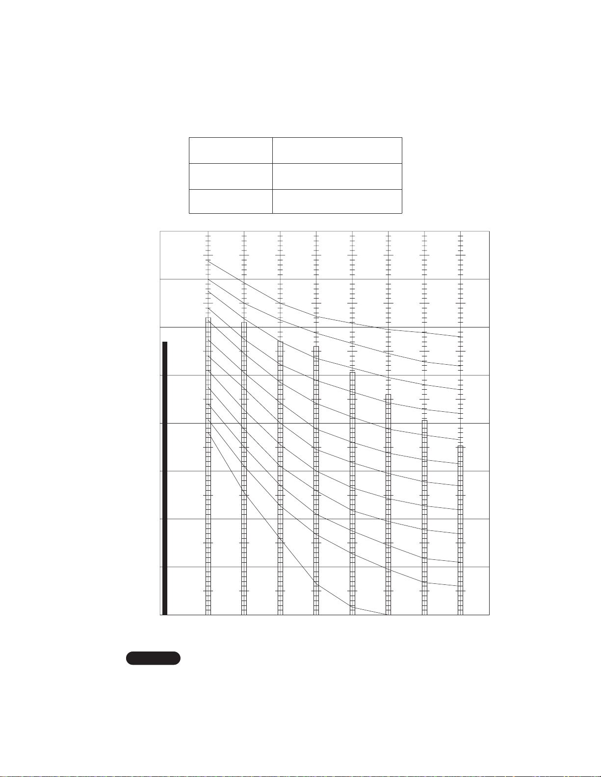
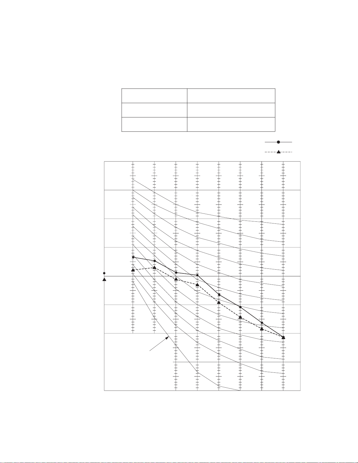
If an ultra long-life fi lter or high performance fi lter (65% by colorimetric method) is installed, the vertical air throw dis-
FORM 121.00-EG1
ISSUE DATE: 5/31/2012
43
JOHNSON CONTROLS
4-Way Air Discharge Ceiling Semi-Concealed, Standard and Mini (JX, JXM Types)
Air Flow Distance/Temperature Chart
tance for heating and cooling will be approximately 0.7 ft less than the values shown in the graph below.
If a high performance fi lter (90% by colorimetric method) or electronic fi lter is installed, the vertical air throw distance
for heating and cooling will be approximately 1.6 ft less than the values shown in the graph below.
JXHX1252N/JXHX1852N
Heating : Distribution of wind velocity
(Strong wind : Discharge angle approx.65 ) (Room temperature approx.68°F)
9.8
6.6
4.9 ft/s
3.3 ft/s
1.6 ft/s
0.98 ft/s
9.8
6.6
3.3
0
Vertical air flow distance (ft.)
16.4 16.413.19.8 6.66.6 3.33.3 013.1 9.8
Heating : Distribution of temperature
(Strong wind : Discharge angle approx.65 )
9.8
6.6
3.3
0
Vertical air flow distance (ft.)
16.4 16.413.19.8 6.66.6 3.33.3 013.1 9.8
Cooling : Distribution of wind velocity
(Strong wind : Discharge angle approx.30 )
9.8
6.6
3.3
Horizontal air flow distance (ft.)
(Room temperature approx.68°F)
91°F
86°F
Horizontal air flow distance (ft.)
(Room temperature approx.80°F)
80°F
4.9 ft/s
75°F
3.3 ft/s
1.6 ft/s
0.98 ft/s
3.3
0
9.8
6.6
3.3
0
9.8
6.6
3.3
1
2
3
4
5
0
Vertical air flow distance (ft.)
16.4 16.413.19.8 6.66.6 3.33.3 013.1 9.8
Cooling : Distribution of temperature
(Strong wind : Discharge angle approx.30 )
9.8
6.6
3.3
0
Vertical air flow distance (ft.)
16.4 16.413.19.8 6.66.6 3.33.3 013.1 9.8
Horizontal air flow distance (ft.)
(Room temperature approx.80°F)
Horizontal air flow distance (ft.)
68°F
71°F
75°F
78°F
0
6
9.8
7
6.6
3.3
8
0
Page 44

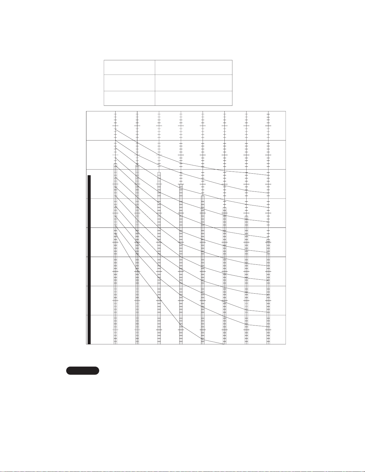
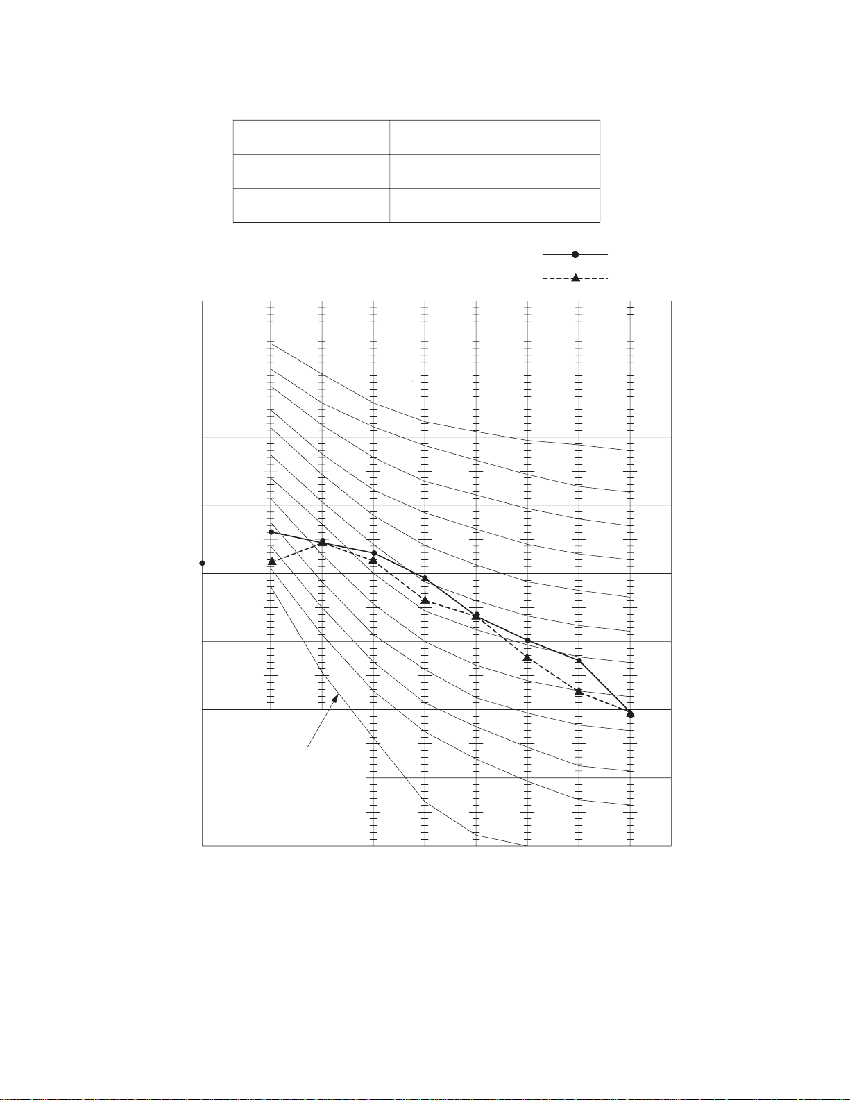
JXHX2452N
FORM 121.00-EG1
ISSUE DATE: 5/31/2012
JOHNSON CONTROLS
44
4-Way Air Discharge Ceiling Semi-Concealed, Standard and Mini (JX, JXM Types)
Heating : Distribution of wind velocity
(Strong wind : Discharge angle approx.65 )
9.8
6.6
(Room temperature approx.68°F)
4.9 ft/s
3.3 ft/s
1.6 ft/s
0.98 ft/s
9.8
6.6
2
3
4
3.3
0
Vertical air flow distance (ft.)
16.4 16.413.19.8 6.66.6 3.33.3 013.1 9.8
Heating : Distribution of temperature
(Strong wind : Discharge angle approx.65 )
9.8
6.6
3.3
0
Vertical air flow distance (ft.)
16.4 16.413.19.8 6.66.6 3.33.3 013.1 9.8
Cooling : Distribution of wind velocity
(Strong wind : Discharge angle approx.30 )
9.8
6.6
Horizontal air flow distance (ft.)
(Room temperature approx.68°F)
91°F
86°F
Horizontal air flow distance (ft.)
(Room temperature approx.80°F)
80°F
75°F
4.9 ft/s
3.3 ft/s
1.6 ft/s
0.98 ft/s
3.3
0
9.8
6.6
3.3
0
9.8
6.6
3.3
5
0
Vertical air flow distance (ft.)
16.4 16.413.19.8 6.66.6 3.33.3 013.1 9.8
Horizontal air flow distance (ft.)
6
7
Cooling : Distribution of temperature
(Strong wind : Discharge angle approx.30 )
9.8
6.6
3.3
8
0
Vertical air flow distance (ft.)
16.4 16.413.19.8 6.66.6 3.33.3 013.1 9.8
Horizontal air flow distance (ft.)
(Room temperature approx.80°F)
68°F
71°F
75°F
78°F
3.3
0
9.8
6.6
3.3
0
Page 45

JXHX3652N
FORM 121.00-EG1
ISSUE DATE: 5/31/2012
45
JOHNSON CONTROLS
4-Way Air Discharge Ceiling Semi-Concealed, Standard and Mini (JX, JXM Types)
Heating : Distribution of wind velocity
(Strong wind : Discharge angle approx.65 )
9.8
6.6
(Room temperature approx.68°F)
4.9 ft/s
3.3 ft/s
1.6 ft/s
0.98 ft/s
9.8
6.6
3.3
Vertical air flow distance (ft.)
0
16.4 16.413.19.8 6.66.6 3.33.3 013.1 9.8
Heating : Distribution of temperature
(Strong wind : Discharge angle approx.65 )
9.8
6.6
3.3
Vertical air flow distance (ft.)
0
16.4 16.413.19.8 6.66.6 3.33.3 013.1 9.8
Cooling : Distribution of wind velocity
(Strong wind : Discharge angle approx.30 )
9.8
6.6
Horizontal air flow distance (ft.)
(Room temperature approx.68°F)
91°F
86°F
Horizontal air flow distance (ft.)
(Room temperature approx.80°F)
80°F
75°F
4.9 ft/s
3.3 ft/s
1.6 ft/s
0.98 ft/s
3.3
0
9.8
6.6
3.3
0
9.8
6.6
1
2
3
4
3.3
Vertical air flow distance (ft.)
0
16.4 16.413.19.8 6.66.6 3.33.3 013.1 9.8
Cooling : Distribution of temperature
(Strong wind : Discharge angle approx.30 )
9.8
6.6
3.3
Vertical air flow distance (ft.)
0
16.4 16.413.19.8 6.66.6 3.33.3 013.1 9.8J
Horizontal air flow distance (ft.)
Horizontal air flow distance (ft.)
(Room temperature approx.80°F)
68°F
71°F
75°F
78°F
3.3
0
9.8
6.6
3.3
0
5
6
7
8
Page 46

FORM 121.00-EG1
ISSUE DATE: 5/31/2012
JOHNSON CONTROLS
46
4-Way Air Discharge Ceiling Semi-Concealed, Standard and Mini (JX, JXM Types)
JXMHX1252N
Heating: Distribution of wind velocity
(Strong wind : Discharge angle approx.60 )
9.8
6.6
(Room temperature approx.68°F)
4.9 ft/s
3.3 ft/s
1.6 ft/s
0.98 ft/s
9.8
6.6
1
2
3
4
3.3
0
Vertical air flow distance (ft.)
16.4 16.413.19.8 6.66.6 3.33.3 013.1 9.8
Heating : Distribution of temperature
(Strong wind : Discharge angle approx.60 )
9.8
6.6
3.3
0
Vertical air flow distance (ft.)
16.4 16.413.19.8 6.66.6 3.33.3 013.1 9.8
Cooling : Distribution of wind velocity
(Strong wind : Discharge angle approx.30 )
9.8
6.6
Horizontal air flow distance (ft.)
(Room temperature approx.68°F)
91°F
86°F
Horizontal air flow distance (ft.)
(Room temperature approx.80°F)
80°F
75°F
4.9 ft/s
3.3 ft/s
1.6 ft/s
3.3
0
9.8
6.6
3.3
0
9.8
6.6
0.98 ft/s
3.3
5
0
Vertical air flow distance (ft.)
16.4 16.413.19.8 6.66.6 3.33.3 013.1 9.8
Horizontal air flow distance (ft.)
6
7
Cooling : Distribution of temperature
(Strong wind : Discharge angle approx.30 )
9.8
6.6
3.3
8
0
Vertical air flow distance (ft.)
16.4 16.413.19.8 6.66.6 3.33.3 013.1 9.8
Horizontal air flow distance (ft.)
(Room temperature approx.80°F)
68°F
71°F
75°F
78°F
3.3
0
9.8
6.6
3.3
0
Page 47

JXMHX1852N
FORM 121.00-EG1
ISSUE DATE: 5/31/2012
47
JOHNSON CONTROLS
4-Way Air Discharge Ceiling Semi-Concealed, Standard and Mini (JX, JXM Types)
Heating : Distribution of wind velocity
(Strong wind : Discharge angle approx.60 )
9.8
6.6
(Room temperature approx.68°F)
4.9 ft/s
3.3 ft/s
1.6 ft/s
0.98 ft/s
9.8
6.6
3.3
0
Vertical air flow distance (ft.)
16.4 16.413.19.8 6.66.6 3.33.3 013.1 9.8
Heating : Distribution of temperature
(Strong wind : Discharge angle approx.60 )
9.8
6.6
3.3
0
Vertical air flow distance (ft.)
16.4 16.413.19.8 6.66.6 3.33.3 013.1 9.8
Cooling : Distribution of wind velocity
(Strong wind : Discharge angle approx.30 )
9.8
6.6
Horizontal air flow distance (ft.)
(Room temperature approx.68°F)
91°F
86°F
Horizontal air flow distance (ft.)
(Room temperature approx.80°F)
80°F
75°F
4.9 ft/s
3.3 ft/s
1.6 ft/s
0.98 ft/s
3.3
0
9.8
6.6
3.3
0
9.8
6.6
1
2
3
4
3.3
0
Vertical air flow distance (ft.)
16.4 16.413.19.8 6.66.6 3.33.3 013.1 9.8
Horizontal air flow distance (ft.)
Cooling : Distribution of temperature
(Strong wind : Discharge angle approx.30 )
9.8
6.6
3.3
0
Vertical air flow distance (ft.)
16.4 16.413.19.8 6.66.6 3.33.3 013.1 9.8
Horizontal air flow distance (ft.)
(Room temperature approx.80°F)
68°F
71°F
75°F
78°F
3.3
0
9.8
6.6
3.3
0
5
6
7
8
Page 48

1
FORM 121.00-EG1
ISSUE DATE: 5/31/2012
JOHNSON CONTROLS
48
1-Way Air Discharge Ceiling Semi-Concealed (JA Type)
2
3
4
5
6
Specifi cations
Unit specifi cations (A)
MODEL No.
POWER SOURCE
PERFORMANCE
Capacity
Air circulation (Hi / Me / Lo) CFM 280 / 250 / 210
Moisture removal (High) Pints / h 1.23 –
ELECTRICAL RATINGS
Voltage rating V 208 230 208 230
Available voltage range V 187 - 253 187 - 253
Running amperes A 0.29 0.28 0.28 0.26
Power input W 48 50 44 46
Power factor % 80 78 76 77
Max. starting amperes A 1111
FEATURES
Controls Microprocessor
Fan speeds 3 and Automatic control
Airflow direction Automatic (Remote control)
Air filter Washable, easy access, long life
Refrigerant control Electronic expansion valve
Operation sound (
Refrigerant tubing connections Flare type
Refrigerant tube diameter
Drain connection 25 A, OD 1-1/4"
Drain pump Max. head 2.1 ft. above drain connection
Panel Optional (JPNR-AH1252N)
Remote controller Optional (JRCS-TM80BGN, JRCS-TRP80ABWLN)
Refrigerant tubing kit / Accessories Optional / –
Color (Approximate value) Munsell 2.5GY 9.0 / 0.5, RAL 9001-GL (resemblant color)
DIMENSIONS & WEIGHT
Unit dimensions
Net weight lbs. (kg) 43 (19.5) – –
Shipping weight lbs. (kg) – 60 (27) 9 (4.0)
Shipping volume ft
Hi / Me / Lo
Liquid tube in. (mm) 1 / 4 (6.35)
Gas tube in. (mm) 1 / 2 (12.7)
Height in. (mm) 13 (330)
Width in. (mm) 29-29 / 32 (760)
Depth in. (mm) 24-3 / 8 (620)
Indoor Unit
Cooling Heating
BTU / h 7,500 8,500
kW 2.2 2.5
) dB-A 33 / 31 / 29
Indoor unit (including panel)
3 (m3
) – 6.0 (0.170) 2.2 (0.062)
JAHX0752N
208 - 230 V / 1ø / 60 Hz
Body Panel
14-3 / 16 (360) 4-13 / 32 (112)
31-3 / 32 (790)
23-15 / 32 (596)
Package
31-1 / 2 (800)
27-9 / 16 (700)
7
8
Rated conditions
Cooling : Indoor air temperature 80°F DB / 67°F WB ; Outdoor air temperature 95°F DB
Heating : Indoor air temperature 70°F DB ; Outdoor air temperature 47°F DB / 43°F WB
Page 49

3. 1-Way Air Discharge Semi-concealed Type (A Type)
FORM 121.00-EG1
ISSUE DATE: 5/31/2012
49
JOHNSON CONTROLS
1-Way Air Discharge Ceiling Semi-Concealed (JA Type)
Unit specifi cations (B)
MODEL No.
POWER SOURCE
PERFORMANCE
Capacity
Air circulation (Hi / Me / Lo) CFM 280 / 250 / 210
Moisture removal (High) Pints / h 2.75 –
ELECTRICAL RATINGS
Voltage rating V 208 230 208 230
Available voltage range V 187 - 253 187 - 253
Running amperes A 0.29 0.28 0.28 0.26
Power input W 48 50 44 46
Power factor % 80 78 76 77
Max. starting amperes A 1111
FEATURES
Controls Microprocessor
Fan speeds 3 and Automatic control
Airflow direction Automatic (Remote control)
Air filter Washable, easy access, long life
Refrigerant control Electronic expansion valve
Operation sound (
Refrigerant tubing connections Flare type
Refrigerant tube diameter
Drain connection 25 A, OD 1-1/4"
Drain pump Max. head 2.1 ft. above drain connection
Panel Optional (JPNR-AH1252N)
Remote controller Optional (JRCS-TM80BGN, JRCS-TRP80ABWLN)
Refrigerant tubing kit / Accessories Optional / –
Color (Approximate value) Munsell 2.5GY 9.0 / 0.5, RAL 9001-GL (resemblant color)
DIMENSIONS & WEIGHT
Unit dimensions
Net weight lbs. (kg) 43 (19.5) – –
Shipping weight lbs. (kg) – 60 (27) 9 (4.0)
Shipping volume ft
Hi / Me / Lo
Liquid tube in. (mm) 1 / 4 (6.35)
Gas tube in. (mm) 1 / 2 (12.7)
Height in. (mm) 13 (330)
Width in. (mm) 29-29 / 32 (760)
Depth in. (mm) 24-3 / 8 (620)
Indoor Unit
Cooling Heating
BTU / h 9,600 11,000
kW 2.8 3.2
) dB-A 33 / 31 / 29
Indoor unit (including panel)
3 (m3
) – 6.0 (0.170) 2.2 (0.062)
JAHX0952N
208 - 230 V / 1ø / 60 Hz
Body Panel
14-3 / 16 (360) 4-13 / 32 (112)
31-3 / 32 (790)
23-15 / 32 (596)
Package
31-1 / 2 (800)
27-9 / 16 (700)
1
2
3
4
5
6
Rated conditions
Cooling : Indoor air temperature 80°F DB / 67°F WB ; Outdoor air temperature 95°F DB
Heating : Indoor air temperature 70°F DB ; Outdoor air temperature 47°F DB / 43°F WB
7
8
Page 50

1
FORM 121.00-EG1
ISSUE DATE: 5/31/2012
JOHNSON CONTROLS
50
1-Way Air Discharge Ceiling Semi-Concealed (JA Type)
2
3
4
5
6
Unit specifi cations (C)
MODEL No.
POWER SOURCE
PERFORMANCE
Capacity
Air circulation (Hi / Me / Lo) CFM 320 / 280 / 250
Moisture removal (High) Pints / h 4.02 –
ELECTRICAL RATINGS
Voltage rating V 208 230 208 230
Available voltage range V 187 - 253 187 - 253
Running amperes A 0.32 0.31 0.34 0.32
Power input W 52 55 50 52
Power factor % 78 77 71 71
Max. starting amperes A 1111
FEATURES
Controls Microprocessor
Fan speeds 3 and Automatic control
Airflow direction Automatic (Remote control)
Air filter Washable, easy access, long life
Refrigerant control Electronic expansion valve
Operation sound (
Refrigerant tubing connections Flare type
Refrigerant tube diameter
Drain connection 25 A, OD 1-1/4"
Drain pump Max. head 2.1 ft. above drain connection
Panel Optional (JPNR-AH1252N)
Remote controller Optional (JRCS-TM80BGN, JRCS-TRP80ABWLN)
Refrigerant tubing kit / Accessories Optional / –
Color (Approximate value) Munsell 2.5GY 9.0 / 0.5, RAL 9001-GL (resemblant color)
DIMENSIONS & WEIGHT
Unit dimensions
Net weight lbs. (kg) 43 (19.5) – –
Shipping weight lbs. (kg) – 64 (29) 9 (4.0)
Shipping volume ft
Hi / Me / Lo
Liquid tube in. (mm) 1 / 4 (6.35)
Gas tube in. (mm) 1 / 2 (12.7)
Height in. (mm) 13 (330)
Width in. (mm) 29-29 / 32 (760)
Depth in. (mm) 24-3 / 8 (620)
Indoor Unit
Cooling Heating
BTU / h 12,000 14,000
kW 3.6 4.2
) dB-A 33 / 31 / 29
Indoor unit (including panel)
3 (m3
) – 6.0 (0.170) 2.2 (0.062)
JAHX1252N
208 - 230 V / 1ø / 60 Hz
Body Panel
14-3 / 16 (360) 4-13 / 32 (112)
31-3 / 32 (790)
23-15 / 32 (596)
Package
31-1 / 2 (800)
27-9 / 16 (700)
7
Rated conditions
8
Cooling : Indoor air temperature 80°F DB / 67°F WB ; Outdoor air temperature 95°F DB
Heating : Indoor air temperature 70°F DB ; Outdoor air temperature 47°F DB / 43°F WB
Page 51

MODEL No.
FORM 121.00-EG1
ISSUE DATE: 5/31/2012
51
JOHNSON CONTROLS
1-Way Air Discharge Ceiling Semi-Concealed (JA Type)
Major Component Specifications
Indoor unit (A)
Power source
Controller P.C.B. Ass'y
Fan...(Number diameter / length in. (mm))
CR-UMHX0762 (Microprocessor)
Centrifugal (1 ... ø 5-1/2 (ø 140))
JAHX0752N
208 - 230 V / 1ø / 60 Hz
Fan motor
Model...Nominal output W DK8-63E280HB...60W
Power source 340 VDC
No. of pole...r.p.m. (230V, High) rpm 8P...880
Coil resistance
(Ambient temperature 68°F)
Run capacitor VAC, μF –
Safety device
Operating temperature Open °F (°C)
RED – WHT : 53.0
WHT – BLU : 53.0
BLU – RED : 53.0
fuse
+4
–5
(141
+2
)
–3
285
Electronic expansion valve
Coil UKV-U012E
Coil resistance (at 68°F)
Valve body UKV-18D30
ORG – GRY : 46 YEL – GRY : 46
RED – GRY : 46 BLK – GRY : 46
Heat exchanger
Coil Aluminum plate fin / Copper tube
Rows...fin pitch in. (mm) 3...7/128 (1.4)
2 (m2
Face area ft
) 1.14 (0.106)
Panel
Model No. JPNR-AH1252N
Auto louver motor MP24ZN
Coil resistance (at 77°F)
Drain pump
Rated
Total head & capacity
(above drain connection)
V, Hz, W
ft. (mm), gal/
min (cc/min)
380 ± 7% / phase
PLD-12230ST
AC230V, 60Hz, 10.8W
2.1 (640), 0.11 (400)
2
3
4
Page 52

1
FORM 121.00-EG1
ISSUE DATE: 5/31/2012
JOHNSON CONTROLS
52
1-Way Air Discharge Ceiling Semi-Concealed (JA Type)
2
3
4
Indoor unit (B)
MODEL No.
Power source
Controller P.C.B. Ass'y
Fan...(Number diameter / length in. (mm))
Fan motor
Model...Nominal output W DK8-63E280HB...60W
Power source 340 VDC
No. of pole...r.p.m. (230V, High) rpm 8P...880
Coil resistance
(Ambient temperature 68°F)
Run capacitor VAC, μF –
Safety device
Operating temperature Open °F (°C)
Electronic expansion valve
Coil UKV-U012E
Coil resistance (at 68°F)
Valve body UKV-18D30
Heat exchanger
Coil Aluminum plate fin / Copper tube
Rows...fin pitch in. (mm) 3...7/128 (1.4)
Face area ft
Panel
Model No. JPNR-AH1252N
Auto louver motor MP24ZN
Coil resistance (at 77°F)
Drain pump
Rated
Total head & capacity
(above drain connection)
2 (m2
) 1.14 (0.106)
V, Hz, W
ft. (mm), gal/
min (cc/min)
ORG – GRY : 46 YEL – GRY : 46
RED – GRY : 46 BLK – GRY : 46
CR-UMHX0762 (Microprocessor)
Centrifugal (1 ... ø 5-1/2 (ø 140))
RED – WHT : 53.0
WHT – BLU : 53.0
BLU – RED : 53.0
JAHX0952N
208 - 230 V / 1ø / 60 Hz
fuse
+4
–5
(141
+2
–3
285
380 ± 7% / phase
PLD-12230ST
AC230V, 60Hz, 10.8W
2.1 (640), 0.11 (400)
)
5
6
7
8
Page 53

3. 1-Way Air Discharge Semi-concealed Type (A Type)
FORM 121.00-EG1
ISSUE DATE: 5/31/2012
53
JOHNSON CONTROLS
1-Way Air Discharge Ceiling Semi-Concealed (JA Type)
Indoor unit (C)
MODEL No.
Power source
Controller P.C.B. Ass'y
Fan...(Number diameter / length in. (mm))
CR-UMHX0762 (Microprocessor)
Centrifugal (1 ... ø 5-1/2 (ø 140))
Fan motor
Model...Nominal output W DK8-63E280HB...60W
Power source 340 VDC
No. of pole...r.p.m. (230V, High) rpm 8P...880
Coil resistance
(Ambient temperature 68°F)
Run capacitor VAC, μF –
RED – WHT : 53.0
WHT – BLU : 53.0
BLU – RED : 53.0
Safety device
Operating temperature Open °F (°C)
Electronic expansion valve
Coil UKV-U012E
Coil resistance (at 68°F)
Valve body UKV-18D30
ORG – GRY : 46 YEL – GRY : 46
RED – GRY : 46 BLK – GRY : 46
Heat exchanger
Coil Aluminum plate fin / Copper tube
Rows...fin pitch in. (mm) 3...7/128 (1.4)
2 (m2
Face area ft
) 1.14 (0.106)
Panel
Model No. JPNR-AH1252N
Auto louver motor MP24ZN
Coil resistance (at 77°F)
Drain pump
Rated
Total head & capacity
(above drain connection)
V, Hz, W
ft. (mm), gal/
min (cc/min)
JAHX1252N
208 - 230 V / 1ø / 60 Hz
fuse
+4
–5
(141
+2
–3
285
380 ± 7% / phase
PLD-12230ST
AC230V, 60Hz, 10.8W
2.1 (640), 0.11 (400)
)
1
2
3
5
6
7
8
Page 54

Indoor unit: 7, 9, 12 Type
FORM 121.00-EG1
ISSUE DATE: 5/31/2012
JOHNSON CONTROLS
54
Dimensional Data
1-Way Air Discharge Ceiling Semi-Concealed (JA Type)
6-11/16
3-5/32
1-3/16
12-19/64
1-49/64
5
2-9/16
11
1-27/64
25-15/16
28-47/64
22-3/64
23-15/64
3-47/643-47/64
15-3/4
23-5/8
1-19/64
10-1/32
5-19/64 1-49/64
11-7/32
2-31/64
9-29/64
3-3/16
ø4-1/8
ø6-3/8
4-9/64
3 4 6
ø4-29/64
For fresh air intake detail (ø3-15/16)
ø3-15/16
ø4-1/8
4-9/64
For discharge duct detail (ø5-29/32)
29-59/64
1-27/64
Refrigerant liquid line ø1/4” (ø6.35) (flare)
Air intake grille
Refrigerant gas line ø1/2” (ø12.7) (flare)
Air outlet
Drain connection VP25 (0D ø1-1/4”)
12345
3-25/32
22-3/64
1-3/16”)
×
15/32”)
×
6-11/16
6-11/16
9-31/64”
×
Wireless remote controller the reception department instation department
Power supply outlet
678
For discharge duct (ø5-29/32”)
For fresh air intake (ø3-15/16”)11Inter-unit control wiring
Suspension holes (ø4-15/32”
9
10
Filter dimension
(20-55/64”
8-5/64
24-13/32
1-31/32 or more19-11/16 or more
39-3/8 or more
1-31/32 or more
39-3/8 or more
1-31/32 or more
Page 55

60Hz
FORM 121.00-EG1
ISSUE DATE: 5/31/2012
55
JOHNSON CONTROLS
1-Way Air Discharge Ceiling Semi-Concealed (JA Type)
Noise Criterion Curves
MODEL :
SOUND LEVEL :
CONDITION : Under the unit 4.9 ft
JAHX0752N
JAHX0952N
HIGH 33 dB(A) / LOW 29 dB(A)
MODEL :
SOUND LEVEL :
CONDITION : Under the unit 4.9 ft
JAHX1252N
HIGH 36 dB(A) / LOW 31 dB(A)
1
2
3
4
5
6
7
8
Page 56

Heating equipment
FORM 121.00-EG1
ISSUE DATE: 5/31/2012
JOHNSON CONTROLS
56
1-Way Air Discharge Ceiling Semi-Concealed (JA Type)
Air Flow Distance / Temperature Chart
Wind velocity
distribution
0
3.3
6.6
Analtitude(ft)
9.8
13.1
(Immediate wind A blow angle 60 degrees)
4.9 ft/s
3.3 ft/s
1.6 ft/s
1.0 ft/s
3.3 6.6 9.8 13.1 16.4 19.7 23.0 26.2 29.5 32.80
Horizontal distance(ft)
(Room themperature 68 degrees Fahrenheit)
2
3
4
5
Heating equipment
Temperature
distribution
Cooling equipment
Wind velocity
distribution
0
3.3
6.6
Analtitude(ft)
9.8
13.1
0
3.3
6.6
Analtitude(ft)
9.8
13.1
(Immediate wind A blow angle 60 degrees)
91
°F
86
°F
80
°F
75
°F
3.3 6.6 9.8 13.1 16.4 19.7 23.0 26.2 29.5 32.80
Horizontal distance(ft)
(Immediate wind A blow angle 15 degrees)
4.9 ft/s
3.3 ft/s
1.6 ft/s
1.0 ft/s
3.3 6.6 9.8 13.1 16.4 19.7 23.0 26.2 29.5 32.80
Horizontal distance(ft)
(Room themperature 68 degrees Fahrenheit)
(Room themperature 80 degrees Fahrenheit)
6
Cooling equipment
Temperature
distribution
0
3.3
7
6.6
Analtitude(ft)
9.8
8
13.1
3.3 6.6 9.8 13.1 16.4 19.7 23.0 26.2 29.5 32.80
(Immediate wind A blow angle 15 degrees)
68
°F
71
°F
75
°F
78
°F
Horizontal distance(ft)
(Room themperature 80 degrees Fahrenheit)
Page 57

MODEL No.
FORM 121.00-EG1
ISSUE DATE: 5/31/2012
57
JOHNSON CONTROLS
Slim Concealed Duct, Standard and Slim (JU, JUM Type)
Unit specifications (A)
POWER SOURCE
PERFORMANCE
Capacity
Air circulation (Hi / Me / Lo) CFM 353 / 300 / 247
Moisture removal (High) Pints / h 1.69 –
External static pressure (High) in. WG
ELECTRICAL RATINGS
Voltage rating V 208 230 208 230
Available voltage range V 187 - 253 187 - 253
Running amperes A 0.45 0.49 0.42 0.46
Power input W 92 112 87 104
Power factor % 99 99 99 99
Max. starting amperes A 2222
FEATURES
Controls Microprocessor
Fan speeds 3 and Automatic control
Air fi lter Field supply
Refrigerant control Electronic expansion valve
Operation sound (
Using the booster cable (Hi / Me / Lo) dB-A 35 / 32 / 29
Refrigerant tubing connections Flare type
Refrigerant tube diameter
Drain connection 25 A, OD 1-1/4”
Drain pump Max. head 1.6 ft. above drain connection
Remote controller Optional (JRCS-TM80BGN, JRCS-BH80AABWLN)
Refrigerant tubing kit / Accessories – / Booster cable
Color (Approximate value) –
DIMENSIONS & WEIGHT
Unit dimensions
Net weight lbs. (kg) 53 (24)
Shipping weight lbs. (kg) 62 (28)
Shipping volume ft
Hi / Me / Lo
Liquid tube in. (mm) 1 / 4 (6.35)
Gas tube in. (mm) 1 / 2 (12.7)
Height in. (mm) 12-7 / 32 (310) 14-3 / 32 (358)
Width in. (mm) 27-9 / 16 (700) 35-3 / 32 (891)
Depth in. (mm) 24-13 / 16 (630) 30-13 / 16 (783)
Indoor Unit JUHX0762N
208 - 230 V / 1ø / 60 Hz
Cooling Heating
BTU / h 7,500 8,500
kW 2.2 2.5
0.28 : At shipment 0.40 : Using the booster cable
) dB-A 31 / 28 / 24
Unit dimensions Package dimensions
3 (m3
) 8.8 (0.250)
1
2
3
4
5
Rated conditions
Cooling : Indoor air temperature 80°F DB / 67°F WB ; Outdoor air temperature 95°F DB
Heating : Indoor air temperature 70°F DB ; Outdoor air temperature 47°F DB / 43°F WB
6
7
8
Page 58

2
FORM 121.00-EG1
ISSUE DATE: 5/31/2012
JOHNSON CONTROLS
58
Slim Concealed Duct, Standard and Slim (JU, JUM Type)
Specifications
Unit specifications (B)
3
4
5
6
MODEL No.
SOURCE
PERFORMANCE
Capacity
Air circulation (Hi / Me / Lo) CFM 353 / 300 / 247
Moisture removal (High) Pints / h 1.69 –
External static pressure (High) in. WG
ELECTRICAL RATINGS
Voltage rating V 208 230 208 230
Available voltage range V 187 - 253 187 - 253
Running amperes A 0.45 0.49 0.42 0.46
Power input W 92 112 87 104
Power factor % 99 99 99 99
Max. starting amperes A 2222
FEATURES
Controls Microprocessor
Fan speeds 3 and Automatic control
Air fi lter Field supply
Refrigerant control Electronic expansion valve
Operation sound (
Using the booster cable (Hi / Me / Lo) dB-A 35 / 32 / 29
Refrigerant tubing connections Flare type
Refrigerant tube diameter
Drain connection 25 A, OD 1-1/4”
Drain pump Max. head 1.6 ft. above drain connection
Remote controller Optional (JRCS-TM80BGN, JRCS-BH80AABWLN)
Refrigerant tubing kit / Accessories – / Booster cable
Color (Approximate value) –
DIMENSIONS & WEIGHT
Unit dimensions
Net weight lbs. (kg) 53 (24)
Shipping weight lbs. (kg) 62 (28)
Shipping volume ft
Hi / Me / Lo
Liquid tube in. (mm) 1 / 4 (6.35)
Gas tube in. (mm) 1 / 2 (12.7)
Height in. (mm) 12-1 / 4 (310) 14-1 / 8 (358)
Width in. (mm) 27-1 / 2 (700) 35-1 / 8 (891)
Depth in. (mm) 24-3 / 4 (630) 30-7 / 8 (783)
Indoor Unit JUHX0962N
208 - 230 V / 1ø / 60 Hz
Cooling Heating
BTU / h 9,600 11,000
kW 2.8 3.2
0.28 : At shipment 0.40 : Using the booster cable
) dB-A 31 / 28 / 24
Unit dimensions Package dimensions
3 (m3
) 8.8 (0.250)
7
8
Rated conditions
Cooling : Indoor air temperature 80°F DB / 67°F WB ; Outdoor air temperature 95°F DB
Heating : Indoor air temperature 70°F DB ; Outdoor air temperature 47°F DB / 43°F WB
Page 59

MODEL No.
FORM 121.00-EG1
ISSUE DATE: 5/31/2012
59
JOHNSON CONTROLS
Slim Concealed Duct, Standard and Slim (JU, JUM Type)
Unit specifications (C)
POWER SOURCE
PERFORMANCE
Capacity
Air circulation (Hi / Me / Lo) CFM 424 / 371 / 318
Moisture removal (High) Pints / h 3.80 –
External static pressure (High) in. WG
ELECTRICAL RATINGS
Voltage rating V 208 230 208 230
Available voltage range V 187 - 253 187 - 253
Running amperes A 0.52 0.55 0.49 0.54
Power input W 107 125 100 122
Power factor % 99 99 99 99
Max. starting amperes A 2222
FEATURES
Controls Microprocessor
Fan speeds 3 and Automatic control
Air fi lter Field supply
Refrigerant control Electronic expansion valve
Operation sound (
Using the booster cable (Hi / Me / Lo) dB-A 35 / 32 / 29
Refrigerant tubing connections Flare type
Refrigerant tube diameter
Drain connection 25 A, OD 1-1/4”
Drain pump Max. head 1.6 ft. above drain connection
Remote controller Optional (JRCS-TM80BGN, JRCS-BH80AABWLN)
Refrigerant tubing kit / Accessories – / Booster cable
Color (Approximate value) –
DIMENSIONS & WEIGHT
Unit dimensions
Net weight lbs. (kg) 53 (24)
Shipping weight lbs. (kg) 62 (28)
Shipping volume ft
Hi / Me / Lo
Liquid tube in. (mm) 1 / 4 (6.35)
Gas tube in. (mm) 1 / 2 (12.7)
Height in. (mm) 12-7 / 32 (310) 14-3 / 32 (358)
Width in. (mm) 27-9 / 16 (700) 35-3 / 32 (891)
Depth in. (mm) 24-13 / 16 (630) 30-13 / 16 (783)
Indoor Unit JUHX1262N
208 - 230 V / 1ø / 60 Hz
Cooling Heating
BTU / h 12,000 14,000
kW 3.6 4.2
0.28 : At shipment 0.40 : Using the booster cable
) dB-A 31 / 28 / 24
Unit dimensions Package dimensions
3 (m3
) 8.8 (0.250)
1
2
3
4
5
Rated conditions
Cooling : Indoor air temperature 80°F DB / 67°F WB ; Outdoor air temperature 95°F DB
Heating : Indoor air temperature 70°F DB ; Outdoor air temperature 47°F DB / 43°F WB
6
7
8
Page 60

2
FORM 121.00-EG1
ISSUE DATE: 5/31/2012
JOHNSON CONTROLS
60
Slim Concealed Duct, Standard and Slim (JU, JUM Type)
Unit specifications (D)
3
4
5
6
MODEL No.
SOURCE
PERFORMANCE
Capacity
Air circulation (Hi / Me / Lo) CFM 424 / 371 / 318
Moisture removal (High) Pints / h 6.34 –
External static pressure (High) in. WG
ELECTRICAL RATINGS
Voltage rating V 208 230 208 230
Available voltage range V 187 - 253 187 - 253
Running amperes A 0.52 0.55 0.49 0.54
Power input W 107 125 100 122
Power factor % 99 99 99 99
Max. starting amperes A 2222
FEATURES
Controls Microprocessor
Fan speeds 3 and Automatic control
Air fi lter Field supply
Refrigerant control Electronic expansion valve
Operation sound (
Using the booster cable (Hi / Me / Lo) dB-A 37 / 34 / 31
Refrigerant tubing connections Flare type
Refrigerant tube diameter
Drain connection 25 A, OD 1-1/4”
Drain pump Max. head 1.6 ft. above drain connection
Remote controller Optional (JRCS-TM80BGN, JRCS-BH80AABWLN)
Refrigerant tubing kit / Accessories – / Booster cable
Color (Approximate value) –
DIMENSIONS & WEIGHT
Unit dimensions
Net weight lbs. (kg) 55 (25)
Shipping weight lbs. (kg) 62 (28)
Shipping volume ft
Hi / Me / Lo
Liquid tube in. (mm) 1 / 4 (6.35)
Gas tube in. (mm) 1 / 2 (12.7)
Height in. (mm) 12-1 / 4 (310) 14-1 / 8 (358)
Width in. (mm) 27-1 / 2 (700) 35-1 / 8 (891)
Depth in. (mm) 24-3 / 4 (630) 30-7 / 8 (783)
Indoor Unit JUHX1562N
208 - 230 V / 1ø / 60 Hz
Cooling Heating
BTU / h 15,000 17,000
kW 4.5 5.0
0.28 : At shipment 0.44 : Using the booster cable
) dB-A 33 / 30 / 26
Unit dimensions Package dimensions
3 (m3
) 8.8 (0.250)
7
8
Rated conditions
Cooling : Indoor air temperature 80°F DB / 67°F WB ; Outdoor air temperature 95°F DB
Heating : Indoor air temperature 70°F DB ; Outdoor air temperature 47°F DB / 43°F WB
Page 61

MODEL No.
FORM 121.00-EG1
ISSUE DATE: 5/31/2012
61
JOHNSON CONTROLS
Slim Concealed Duct, Standard and Slim (JU, JUM Type)
Unit specifications (E)
POWER SOURCE
PERFORMANCE
Capacity
Air circulation (Hi / Me / Lo) CFM 671 / 565 / 459
Moisture removal (High) Pints / h 6.34 –
External static pressure (High) in. WG
ELECTRICAL RATINGS
Voltage rating V 208 230 208 230
Available voltage range V 187 - 253 187 - 253
Running amperes A 0.90 0.96 0.89 0.95
Power input W 183 219 182 214
Power factor % 99 99 98 98
Max. starting amperes A 3333
FEATURES
Controls Microprocessor
Fan speeds 3 and Automatic control
Air fi lter Field supply
Refrigerant control Electronic expansion valve
Operation sound (
Using the booster cable (Hi / Me / Lo) dB-A 40 / 37 / 33
Refrigerant tubing connections Flare type
Refrigerant tube diameter
Drain connection 25 A, OD 1-1/4”
Drain pump Max. head 1.6 ft. above drain connection
Remote controller Optional (JRCS-TM80BGN, JRCS-BH80AABWLN)
Refrigerant tubing kit / Accessories – / Booster cable
Color (Approximate value) –
DIMENSIONS & WEIGHT
Unit dimensions
Net weight lbs. (kg) 71 (32)
Shipping weight lbs. (kg) 82 (37)
Shipping volume ft
Hi / Me / Lo
Liquid tube in. (mm) 1 / 4 (6.35)
Gas tube in. (mm) 1 / 2 (12.7)
Height in. (mm) 12-7 / 32 (310) 14-3 / 32 (358)
Width in. (mm) 39-3 / 16 (1000) 46-7 / 16 (1191)
Depth in. (mm) 24-13 / 16 (630) 30-13 / 16 (783)
Indoor Unit JUHX1862N
208 - 230 V / 1ø / 60 Hz
Cooling Heating
BTU / h 19,000 21,000
kW 5.6 6.3
0.32 : At shipment 0.48 : Using the booster cable
) dB-A 36 / 32 / 27
Unit dimensions Package dimensions
3 (m3
) 11.8 (0.334)
1
2
3
4
5
Rated conditions
Cooling : Indoor air temperature 80°F DB / 67°F WB ; Outdoor air temperature 95°F DB
Heating : Indoor air temperature 70°F DB ; Outdoor air temperature 47°F DB / 43°F WB
6
7
8
Page 62

2
FORM 121.00-EG1
ISSUE DATE: 5/31/2012
JOHNSON CONTROLS
62
Slim Concealed Duct, Standard and Slim (JU, JUM Type)
Unit specifications (F)
3
4
5
MODEL No.
POWER SOURCE
PERFORMANCE
Capacity
Air circulation (Hi / Me / Lo) CFM 671 / 565 / 459
Moisture removal (High) Pints / h 7.40 –
External static pressure (High) in. WG
ELECTRICAL RATINGS
Voltage rating V 208 230 208 230
Available voltage range V 187 - 253 187 - 253
Running amperes A 0.90 0.96 0.89 0.95
Power input W 183 219 182 214
Power factor % 98 99 98 98
Max. starting amperes A 3333
FEATURES
Controls Microprocessor
Fan speeds 3 and Automatic control
Air fi lter Field supply
Refrigerant control Electronic expansion valve
Operation sound (
Using the booster cable (Hi / Me / Lo) dB-A 40 / 37 / 33
Refrigerant tubing connections Flare type
Refrigerant tube diameter
Drain connection 25 A, OD 1-1/4”
Drain pump Max. head 1.6 ft. above drain connection
Remote controller Optional (JRCS-TM80BGN, JRCS-BH80AABWLN)
Refrigerant tubing kit / Accessories – / Booster cable
Color (Approximate value) –
DIMENSIONS & WEIGHT
Unit dimensions
Net weight lbs. (kg) 71 (32)
Shipping weight lbs. (kg) 82 (37)
Shipping volume ft
Hi / Me / Lo
Liquid tube in. (mm) 3 / 8 (9.52)
Gas tube in. (mm) 5 / 8 (15.88)
Height in. (mm) 12-7 / 32 (310) 14-3 / 32 (358)
Width in. (mm) 39-3 / 16 (1000) 46-7 / 16 (1191)
Depth in. (mm) 24-13 / 16 (630) 30-13 / 16 (783)
Indoor Unit JUHX2462N
208 - 230 V / 1ø / 60 Hz
Cooling Heating
BTU / h 25,000 27,000
kW 7.3 8.0
0.32 : At shipment 0.48 : Using the booster cable
) dB-A 36 / 32 / 27
Unit dimensions Package dimensions
3 (m3
) 11.8 (0.334)
6
7
8
Rated conditions
Cooling : Indoor air temperature 80°F DB / 67°F WB ; Outdoor air temperature 95°F DB
Heating : Indoor air temperature 70°F DB ; Outdoor air temperature 47°F DB / 43°F WB
Page 63

MODEL No.
FORM 121.00-EG1
ISSUE DATE: 5/31/2012
63
JOHNSON CONTROLS
Slim Concealed Duct, Standard and Slim (JU, JUM Type)
Unit specifications (G)
POWER SOURCE
PERFORMANCE
Capacity
Air circulation (Hi / Me / Lo) CFM 1,060 / 919 / 742
Moisture removal (High) Pints / h 8.88 –
External static pressure (High) in. WG
ELECTRICAL RATINGS
Voltage rating V 208 230 208 230
Available voltage range V 187 - 253 187 - 253
Running amperes A 1.15 1.25 1.10 1.18
Power input W 235 282 224 267
Power factor % 98 98 98 98
Max. starting amperes A 4444
FEATURES
Controls Microprocessor
Fan speeds 3 and Automatic control
Air fi lter Field supply
Refrigerant control Electronic expansion valve
Operation sound (
Using the booster cable (Hi / Me / Lo) dB-A 42 / 38 / 33
Refrigerant tubing connections Flare type
Refrigerant tube diameter
Drain connection 25 A, OD 1-1/4”
Drain pump Max. head 1.6 ft. above drain connection
Remote controller Optional (JRCS-TM80BGN, JRCS-BH80AABWLN)
Refrigerant tubing kit / Accessories – / Booster cable
Color (Approximate value) –
DIMENSIONS & WEIGHT
Unit dimensions
Net weight lbs. (kg) 104 (47)
Shipping weight lbs. (kg) 115 (52)
Shipping volume ft
Hi / Me / Lo
Liquid tube in. (mm) 3 / 8 (9.52)
Gas tube in. (mm) 5 / 8 (15.88)
Height in. (mm) 12-7 / 32 (310) 14-3 / 32 (358)
Width in. (mm) 58-9 / 32 (1480) 65-25 / 32 (1671)
Depth in. (mm) 24-13 / 16 (630) 30-13 / 16 (783)
Indoor Unit JUHX3662N
208 - 230 V / 1ø / 60 Hz
Cooling Heating
BTU / h 36,000 39,000
kW 10.6 11.4
0.32 : At shipment 0.49 : Using the booster cable
) dB-A 38 / 33 / 31
Unit dimensions Package dimensions
3 (m3
) 16.5 (0.468)
1
2
3
4
5
Rated conditions
Cooling : Indoor air temperature 80°F DB / 67°F WB ; Outdoor air temperature 95°F DB
Heating : Indoor air temperature 70°F DB ; Outdoor air temperature 47°F DB / 43°F WB
6
7
8
Page 64

2
FORM 121.00-EG1
ISSUE DATE: 5/31/2012
JOHNSON CONTROLS
64
Slim Concealed Duct, Standard and Slim (JU, JUM Type)
Unit specifications (H)
3
4
5
6
MODEL No.
SOURCE
PERFORMANCE
Capacity
Air circulation (Hi / Me / Lo) CFM 1,166 / 1,060 / 883
Moisture removal (High) Pints / h 14.0 –
External static pressure (High) in. WG
ELECTRICAL RATINGS
Voltage rating V 208 230 208 230
Available voltage range V 187 - 253 187 - 253
Running amperes A 1.25 1.34 1.13 1.20
Power input W 254 301 230 271
Power factor % 98 98 98 99
Max. starting amperes A 4444
FEATURES
Controls Microprocessor
Fan speeds 3 and Automatic control
Air fi lter Field supply
Refrigerant control Electronic expansion valve
Operation sound (
Using the booster cable (Hi / Me / Lo) dB-A 44 / 40 / 35
Refrigerant tubing connections Flare type
Refrigerant tube diameter
Drain connection 25 A, OD 1-1/4”
Drain pump Max. head 1.6 ft. above drain connection
Remote controller Optional (JRCS-TM80BGN, JRCS-BH80AABWLN)
Refrigerant tubing kit / Accessories – / Booster cable
Color (Approximate value) –
DIMENSIONS & WEIGHT
Unit dimensions
Net weight lbs. (kg) 104 (47)
Shipping weight lbs. (kg) 115 (52)
Shipping volume ft
Hi / Me / Lo
Liquid tube in. (mm) 3 / 8 (9.52)
Gas tube in. (mm) 5 / 8 (15.88)
Height in. (mm) 12-1 / 4 (310) 14-1 / 8 (358)
Width in. (mm) 58-3 / 8 (1480) 65-3 / 4 (1671)
Depth in. (mm) 24-3 / 4 (630) 30-7 / 8 (783)
Indoor Unit JUHX4862N
208 - 230 V / 1ø / 60 Hz
Cooling Heating
BTU / h 47,800 54,600
kW 14.0 16.0
0.31 : At shipment 0.45 : Using the booster cable
) dB-A 40 / 37 / 33
Unit dimensions Package dimensions
3 (m3
) 16.5 (0.468)
7
8
Rated conditions
Cooling : Indoor air temperature 80°F DB / 67°F WB ; Outdoor air temperature 95°F DB
Heating : Indoor air temperature 70°F DB ; Outdoor air temperature 47°F DB / 43°F WB
Page 65

MODEL No.
FORM 121.00-EG1
ISSUE DATE: 5/31/2012
65
JOHNSON CONTROLS
Slim Concealed Duct, Standard and Slim (JU, JUM Type)
Unit specifications (I)
SOURCE
PERFORMANCE
Capacity
Air circulation (Hi / Me / Lo) CFM 1,166 / 1,060 / 883
Moisture removal (High) Pints / h 14.0 –
External static pressure (High) in. WG
ELECTRICAL RATINGS
Voltage rating V 208 230 208 230
Available voltage range V 187 - 253 187 - 253
Running amperes A 1.25 1.34 1.13 1.20
Power input W 254 301 230 271
Power factor % 98 98 98 99
Max. starting amperes A 4444
FEATURES
Controls Microprocessor
Fan speeds 3 and Automatic control
Air fi lter Field supply
Refrigerant control Electronic expansion valve
Operation sound (
Using the booster cable (Hi / Me / Lo) dB-A 44 / 40 / 35
Refrigerant tubing connections Flare type
Refrigerant tube diameter
Drain connection 25 A, OD 1-1/4”
Drain pump Max. head 1.6 ft. above drain connection
Remote controller Optional (JRCS-TM80BGN, JRCS-BH80AABWLN)
Refrigerant tubing kit / Accessories – / Booster cable
Color (Approximate value) –
DIMENSIONS & WEIGHT
Unit dimensions
Net weight lbs. (kg) 104 (47)
Shipping weight lbs. (kg) 115 (52)
Shipping volume ft
Hi / Me / Lo
Liquid tube in. (mm) 3 / 8 (9.52)
Gas tube in. (mm) 5 / 8 (15.88)
Height in. (mm) 12-1 / 4 (310) 14-1 / 8 (358)
Width in. (mm) 58-3 / 8 (1480) 65-3 / 4 (1671)
Depth in. (mm) 24-3 / 4 (630) 30-7 / 8 (783)
Indoor Unit JUHX5462N
208 - 230 V / 1ø / 60 Hz
Cooling Heating
BTU / h 54,600 61,400
kW 16.0 18.0
0.31 : At shipment 0.45 : Using the booster cable
) dB-A 40 / 37 / 33
Unit dimensions Package dimensions
3 (m3
) 16.5 (0.468)
1
2
3
4
5
6
Rated conditions
Cooling : Indoor air temperature 80°F DB / 67°F WB ; Outdoor air temperature 95°F DB
Heating : Indoor air temperature 70°F DB ; Outdoor air temperature 47°F DB / 43°F WB
7
8
Page 66

2
FORM 121.00-EG1
ISSUE DATE: 5/31/2012
JOHNSON CONTROLS
66
Slim Concealed Duct, Standard and Slim (JU, JUM Type)
Unit specifications (J)
3
4
5
6
MODEL No.
POWER SOURCE
PERFORMANCE
Capacity
Air circulation (Hi / Me / Lo) CFM 283 / 247 / 212
Moisture removal (High) Pints / h 0.6 –
External static pressure (High) in. WG 0.04 : At shipment 0.12 :
ELECTRICAL RATINGS
Voltage rating V 208 230 208 230
Available voltage range V 187 - 253 187 - 253
Running amperes A 0.22 0.21 0.23 0.22
Power input W 30 32 30 32
Power factor % 65 65 62 62
Max. starting amperes A ––––
FEATURES
Controls Microprocessor
Timer ON / OFF Timer (Max. 72 hr)
Fan speeds 3 and Automatic control
Air fi lter Washable
Refrigerant control Electronic expansion valve
Operation sound (
Using short circuit connection (Hi / Me / Lo)
Refrigerant tubing connections Flare type
Refrigerant tube
diameter
Drain connection
Drain pump Max. head 1.6 ft. above drain connection
Remote controller Optional (JRCS-TM80BGN, JRCS-BH80AABWLN)
Refrigerant tubing kit / Accessories – / Short Circuit Connection
Color (Approximate value) –
DIMENSIONS & WEIGHT
Unit dimensions
Net weight lbs. (kg) 42 (19)
Shipping weight lbs. (kg) 51 (23)
Shipping volume ft
Hi / Me / Lo
Liquid tube in. (mm) 1 / 4 (6.35)
Gas tube in. (mm) 1 / 2 (12.7)
Height in. (mm) 7-7 / 8 (200) 8-21 / 32 (220)
Width in. (mm) 29-17 / 32 (750) 40-35 / 64 (1030)
Depth in. (mm) 25-13 / 64 (640) 29-21 / 64 (745)
Indoor Unit JUMHX0762N
208 - 230 V / 1ø / 60 Hz
Cooling Heating
BTU / h 7,500 8,500
kW 2.2 2.5
Using short circuit connection
) dB-A 28 / 27 / 25
dB-A 30 / 29 / 27
OD 1-1/4”
Unit dimensions
3
(m3) 5.97 (0.169)
Package dimensions
7
8
Rated conditions
Cooling: Indoor air temperature 80°F DB / 67°F WB; Outdoor air temperature 95°F DB
Heating: Indoor air temperature 70°F DB; Outdoor air temperature 47°F DB / 43°F WB
DATA SUBJECT TO CHANGE WITHOUT NOTICE.
Page 67

MODEL No.
FORM 121.00-EG1
ISSUE DATE: 5/31/2012
67
JOHNSON CONTROLS
Slim Concealed Duct, Standard and Slim (JU, JUM Type)
Unit specifications (K)
POWER SOURCE
PERFORMANCE
Capacity
Air circulation (Hi / Me / Lo) CFM 300 / 265 / 230
Moisture removal (High) Pints / h 1.5 –
External static pressure (High) in. WG 0.06 : At shipment 0.12 :
ELECTRICAL RATINGS
Voltage rating V 208 230 208 230
Available voltage range V 187 - 253 187 - 253
Running amperes A 0.26 0.25 0.28 0.28
Power input W 35 37 37 40
Power factor % 65 65 63 63
Max. starting amperes A – – – –
FEATURES
Controls Microprocessor
Timer ON / OFF Timer (Max. 72 hr)
Fan speeds 3 and Automatic control
Air fi lter Washable
Refrigerant control Electronic expansion valve
Operation sound (
Using short circuit connection (Hi / Me / Lo)
Refrigerant tubing connections Flare type
Refrigerant tube
diameter
Drain connection
Drain pump Max. head 1.6 ft. above drain connection
Remote controller Optional (JRCS-TM80BGN, JRCS-BH80AABWLN)
Refrigerant tubing kit / Accessories – / Short Circuit Connection
Color (Approximate value) –
DIMENSIONS & WEIGHT
Unit dimensions
Net weight lbs. (kg) 42 (19)
Shipping weight lbs. (kg) 51 (23)
Shipping volume ft
Hi / Me / Lo
Liquid tube in. (mm) 1 / 4 (6.35)
Gas tube in. (mm) 1 / 2 (12.7)
Height in. (mm) 7-7 / 8 (200) 8-21 / 32 (220)
Width in. (mm) 29-17 / 32 (750) 40-35 / 64 (1030)
Depth in. (mm) 25-13 / 64 (640) 29-21 / 64 (745)
Indoor Unit JUMHX0962N
208 - 230 V / 1ø / 60 Hz
Cooling Heating
BTU / h 9,600 11,000
kW 2.8 3.2
Using short circuit connection
) dB-A 30 / 29 / 27
dB-A 32 / 31 / 29
OD 1-1/4”
Unit dimensions
3
(m3) 5.97 (0.169)
Package dimensions
1
2
3
5
6
Rated conditions
Cooling: Indoor air temperature 80°F DB / 67°F WB; Outdoor air temperature 95°F DB
Heating: Indoor air temperature 70°F DB; Outdoor air temperature 47°F DB / 43°F WB
DATA SUBJECT TO CHANGE WITHOUT NOTICE.
7
8
Page 68

2
FORM 121.00-EG1
ISSUE DATE: 5/31/2012
JOHNSON CONTROLS
68
Slim Concealed Duct, Standard and Slim (JU, JUM Type)
Unit specifications (L)
3
4
5
6
MODEL No.
POWER SOURCE
PERFORMANCE
Capacity
Air circulation (Hi / Me / Lo) CFM 318 / 283 / 247
Moisture removal (High) Pints / h 2.5 –
External static pressure (High) in. WG 0.06 : At shipment 0.16 :
ELECTRICAL RATINGS
Voltage rating V 208 230 208 230
Available voltage range V 187 - 253 187 - 253
Running amperes A 0.28 0.26 0.30 0.37
Power input W 37 39 39 40
Power factor % 64 64 63 47
Max. starting amperes A – – – –
FEATURES
Controls Microprocessor
Timer ON / OFF Timer (Max. 72 hr)
Fan speeds 3 and Automatic control
Air fi lter Washable
Refrigerant control Electronic expansion valve
Operation sound (
Using short circuit connection (Hi / Me / Lo)
Refrigerant tubing connections Flare type
Refrigerant tube
diameter
Drain connection
Drain pump Max. head 1.6 ft. above drain connection
Remote controller Optional (JRCS-TM80BGN, JRCS-BH80AABWLN)
Refrigerant tubing kit / Accessories – / Short Circuit Connection
Color (Approximate value) –
DIMENSIONS & WEIGHT
Unit dimensions
Net weight lbs. (kg) 42 (19)
Shipping weight lbs. (kg) 51 (23)
Shipping volume ft
Hi / Me / Lo
Liquid tube in. (mm) 1 / 4 (6.35)
Gas tube in. (mm) 1 / 2 (12.7)
Height in. (mm) 7-7 / 8 (200) 8-21 / 32 (220)
Width in. (mm) 29-17 / 32 (750) 40-35 / 64 (1030)
Depth in. (mm) 25-13 / 64 (640) 29-21 / 64 (745)
Indoor Unit JUMHX1262N
208 - 230 V / 1ø / 60 Hz
Cooling Heating
BTU / h 12,000 14,000
kW 3.6 4.2
Using short circuit connection
) dB-A 32 / 30 / 28
dB-A 34 / 32 / 30
OD 1-1/4”
Unit dimensions
3
(m3) 5.97 (0.169)
Package dimensions
7
8
Rated conditions
Cooling: Indoor air temperature 80°F DB / 67°F WB; Outdoor air temperature 95°F DB
Heating: Indoor air temperature 70°F DB; Outdoor air temperature 47°F DB / 43°F WB
DATA SUBJECT TO CHANGE WITHOUT NOTICE.
Page 69

MODEL No.
FORM 121.00-EG1
ISSUE DATE: 5/31/2012
69
JOHNSON CONTROLS
Slim Concealed Duct, Standard and Slim (JU, JUM Type)
Unit specifications (M)
POWER SOURCE
PERFORMANCE
Capacity
Air circulation (Hi / Me / Lo) CFM 371 / 336 / 283
Moisture removal (High) Pints / h 3.6 –
External static pressure (High) in. WG 0.06 : At shipment 0.16 :
ELECTRICAL RATINGS
Voltage rating V 208 230 208 230
Available voltage range V 187 - 253 187 - 253
Running amperes A 0.34 0.33 0.36 0.35
Power input W 44 46 47 49
Power factor % 62 61 63 61
Max. starting amperes A – – – –
FEATURES
Controls Microprocessor
Timer ON / OFF Timer (Max. 72 hr)
Fan speeds 3 and Automatic control
Air fi lter Washable
Refrigerant control Electronic expansion valve
Operation sound (
Using short circuit connection (Hi / Me / Lo)
Refrigerant tubing connections Flare type
Refrigerant tube
diameter
Drain connection
Drain pump Max. head 1.6 ft. above drain connection
Remote controller Optional (JRCS-TM80BGN, JRCS-BH80AABWLN)
Refrigerant tubing kit / Accessories – / Short Circuit Connection
Color (Approximate value) –
DIMENSIONS & WEIGHT
Unit dimensions
Net weight lbs. (kg) 42 (19)
Shipping weight lbs. (kg) 51 (23)
Shipping volume ft
Hi / Me / Lo
Liquid tube in. (mm) 1 / 4 (6.35)
Gas tube in. (mm) 1 / 2 (12.7)
Height in. (mm) 7-7 / 8 (200) 8-21 / 32 (220)
Width in. (mm) 29-17 / 32 (750) 40-35 / 64 (1030)
Depth in. (mm) 25-13 / 64 (640) 29-21 / 64 (745)
Indoor Unit JUMHX1562N
208 - 230 V / 1ø / 60 Hz
Cooling Heating
BTU / h 15,000 17,000
kW 4.5 5.0
Using short circuit connection
) dB-A 34 / 32 / 30
dB-A 36 / 34 / 32
OD 1-1/4”
Unit dimensions
3
(m3) 5.97 (0.169)
Package dimensions
1
2
3
4
5
6
Rated conditions
Cooling: Indoor air temperature 80°F DB / 67°F WB; Outdoor air temperature 95°F DB
Heating: Indoor air temperature 70°F DB; Outdoor air temperature 47°F DB / 43°F WB
DATA SUBJECT TO CHANGE WITHOUT NOTICE.
7
8
Page 70

2
FORM 121.00-EG1
ISSUE DATE: 5/31/2012
JOHNSON CONTROLS
70
Slim Concealed Duct, Standard and Slim (JU, JUM Type)
Unit specifications (N)
3
4
5
6
MODEL No.
POWER SOURCE
PERFORMANCE
Capacity
Air circulation (Hi / Me / Lo) CFM 442 / 406 / 353
Moisture removal (High) Pints / h 4.8 –
External static pressure (High) in. WG 0.06 : At shipment 0.16 :
ELECTRICAL RATINGS
Voltage rating V 208 230 208 230
Available voltage range V 187 - 253 187 - 253
Running amperes A 0.47 0.43 0.51 0.47
Power input W 59 61 63 64
Power factor % 61 62 59 59
Max. starting amperes A – – – –
FEATURES
Controls Microprocessor
Timer ON / OFF Timer (Max. 72 hr)
Fan speeds 3 and Automatic control
Air fi lter Washable
Refrigerant control Electronic expansion valve
Operation sound (
Using short circuit connection (Hi / Me / Lo)
Refrigerant tubing connections Flare type
Refrigerant tube
diameter
Drain connection
Drain pump Max. head 1.6 ft. above drain connection
Remote controller Optional (JRCS-TM80BGN, JRCS-BH80AABWLN)
Refrigerant tubing kit / Accessories – / Short Circuit Connection
Color (Approximate value) –
DIMENSIONS & WEIGHT
Unit dimensions
Net weight lbs. (kg) 42 (19)
Shipping weight lbs. (kg) 51 (23)
Shipping volume ft
Hi / Me / Lo
Liquid tube in. (mm) 1 / 4 (6.35)
Gas tube in. (mm) 1 / 2 (12.7)
Height in. (mm) 7-7 / 8 (200) 8-21 / 32 (220)
Width in. (mm) 29-17 / 32 (750) 40-35 / 64 (1030)
Depth in. (mm) 25-13 / 64 (640) 29-21 / 64 (745)
Indoor Unit JUMHX1862N
208 - 230 V / 1ø / 60 Hz
Cooling Heating
BTU / h 19,000 21,000
kW 5.6 6.3
Using short circuit connection
) dB-A 35 / 33 / 31
dB-A 37 / 35 / 32
OD 1-1/4”
Unit dimensions
3
(m3) 5.97 (0.169)
Package dimensions
7
8
Rated conditions
Cooling: Indoor air temperature 80°F DB / 67°F WB; Outdoor air temperature 95°F DB
Heating: Indoor air temperature 70°F DB; Outdoor air temperature 47°F DB / 43°F WB
DATA SUBJECT TO CHANGE WITHOUT NOTICE.
Page 71

MODEL No.
FORM 121.00-EG1
ISSUE DATE: 5/31/2012
71
JOHNSON CONTROLS
Slim Concealed Duct, Standard and Slim (JU, JUM Type)
Major Component Specifications
Indoor unit (A)
Power source
Controller P.C.B. Ass'y
Fan...(Number diameter / length in. (mm))
Fan motor
Model...Nominal output W SFG4X-51E6P...50W
Power source 208 - 230 V / 1ø / 60 Hz
No. of pole...r.p.m. (230V, High) rpm 4P... 834
Coil resistance
(Ambient temperature 68°F)
Run capacitor VAC, μF 440 VAC, 2.5 μF
Safety device
Operating temperature
Electronic expansion valve
Coil UKV-U031E
Coil resistance (at 68°F)
Valve body UKV-18D31
Heat exchanger
Coil Aluminum plate fi n / Copper tube
Rows...fi n pitch in. (mm) 2...1 / 16 (1.5)
Face area ft
Drain pump
Rated
Total head & capacity
(above drain connection)
Open °F (°C) 266 ± 9 (130 ± 5)
Close °F (°C) 181 ± 27 (83 ± 15)
2
(m2) 1.2 (0.111)
V, Hz, W
ft. (mm), gal/
min (cc/min)
BRN – WHT : 86.0 ORG – YEL : 15.9
WHT – VLT : 13.4 YEL – BLK : 30.1
VLT – ORG : 23.4 BLK – PNK : 27.5
ORG – GRY : 46 YEL – GRY : 46
RED – GRY : 46 BLK – GRY : 46
CR-UHX0762 (Microprocessor)
Centrifugal (1 ... ø7-1/2 (ø190))
JUHX0762N
208 - 230 V / 1ø / 60 Hz
fuse
ZPLD-12230ST-XH-B
AC230V, 60Hz, 10.8W
1.6 (500), 0.11 (400)
1
2
3
4
5
6
7
8
Page 72

2
FORM 121.00-EG1
ISSUE DATE: 5/31/2012
JOHNSON CONTROLS
72
Slim Concealed Duct, Standard and Slim (JU, JUM Type)
Major Component Specifications
Indoor unit (B)
3
MODEL No.
Source
Controller P.C.B. Ass'y
Fan...(Number diameter)
Fan motor
Model...Nominal output W SFG4X-51E6P...50W
Source 208 - 230 V / 1ø / 60 Hz
No. of pole...r.p.m. (230V, High) rpm 4P... 834
Coil resistance
(Ambient temperature 68°F)
Run capacitor VAC, μF 440 VAC, 2.5 μF
Safety device
Operating temperature
Electronic expansion valve
Coil UKV-U031E
Coil resistance (at 68°F)
Valve body UKV-18D31
Heat exchanger
Coil Aluminum plate fi n / Copper tube
Rows...fi n pitch in. (mm) 2...1 / 16 (1.5)
Face area ft
Drain pump
Rated
Total head & capacity
(above drain connection)
in. (mm) Centrifugal (1 ... ø7-1/2 (ø190))
BRN – WHT : 86.0 ORG – YEL : 15.9
Open °F (°C) 266 ± 9 (130 ± 5)
Close °F (°C) 181 ± 27 (83 ± 15)
2
(m2) 1.2 (0.111)
V, Hz, W
ft. (mm), gal/
min (cc/min)
WHT – VLT : 13.4 YEL – BLK : 30.1
VLT – ORG : 23.4 BLK – PNK : 27.5
ORG – GRY : 46 YEL – GRY : 46
RED – GRY : 46 BLK – GRY : 46
CR-UHX0762 (Microprocessor)
JUHX0962N
208 - 230 V / 1ø / 60 Hz
fuse
ZPLD-12230ST-XH-B
AC230V, 60Hz, 10.8W
1.6 (500), 0.11 (400)
4
5
6
7
8
Page 73

MODEL No.
FORM 121.00-EG1
ISSUE DATE: 5/31/2012
73
JOHNSON CONTROLS
Slim Concealed Duct, Standard and Slim (JU, JUM Type)
Indoor unit (C)
Power source
Controller P.C.B. Ass'y
Fan...(Number diameter / length in. (mm))
Fan motor
Model...Nominal output W SFG4X-51D6P...70W
Power source 208 - 230 V / 1ø / 60 Hz
No. of pole...r.p.m. (230V, High) rpm 4P... 834
Coil resistance
(Ambient temperature 68°F)
Run capacitor VAC, μF 440 VAC, 3.5 μF
Safety device
Operating temperature
Electronic expansion valve
Coil UKV-U031E
Coil resistance (at 68°F)
Valve body UKV-18D31
Heat exchanger
Coil Aluminum plate fi n / Copper tube
Rows...fi n pitch in. (mm) 2...1 / 16 (1.5)
Face area ft
Drain pump
Rated
Total head & capacity
(above drain connection)
Open °F (°C) 266 ± 9 (130 ± 5)
Close °F (°C) 181 ± 27 (83 ± 15)
2
(m2) 1.2 (0.111)
V, Hz, W
ft. (mm), gal/
min (cc/min)
BRN – WHT : 86.0 ORG – YEL : 15.9
WHT – VLT : 13.4 YEL – BLK : 30.1
VLT – ORG : 23.4 BLK – PNK : 27.5
ORG – GRY : 46 YEL – GRY : 46
RED – GRY : 46 BLK – GRY : 46
CR-UHX0762 (Microprocessor)
Centrifugal (1 ... ø7-1/2 (ø190))
JUHX1262N
208 - 230 V / 1ø / 60 Hz
fuse
ZPLD-12230ST-XH-B
AC230V, 60Hz, 10.8W
1.6 (500), 0.11 (400)
1
2
3
4
5
6
7
8
Page 74

2
FORM 121.00-EG1
ISSUE DATE: 5/31/2012
JOHNSON CONTROLS
74
Slim Concealed Duct, Standard and Slim (JU, JUM Type)
Indoor unit (D)
3
MODEL No.
Source
Controller P.C.B. Ass'y
Fan...(Number diameter)
Fan motor
Model...Nominal output W SFG4X-51D6P...70W
Source 208 - 230 V / 1ø / 60 Hz
No. of pole...r.p.m. (230V, High) rpm 4P... 834
Coil resistance
(Ambient temperature 68°F)
Run capacitor VAC, μF 440 VAC, 3.5 μF
Safety device
Operating temperature
Electronic expansion valve
Coil UKV-U031E
Coil resistance (at 68°F)
Valve body UKV-25D32
Heat exchanger
Coil Aluminum plate fi n / Copper tube
Rows...fi n pitch in. (mm) 3...1 / 16 (1.5)
Face area ft
Drain pump
Rated
Total head & capacity
(above drain connection)
in. (mm) Centrifugal (1 ... ø7-1/2 (ø190))
BRN – WHT : 86.0 ORG – YEL : 15.9
Open °F (°C) 266 ± 9 (130 ± 5)
Close °F (°C) 181 ± 27 (83 ± 15)
2
(m2) 1.2 (0.111)
V, Hz, W
ft. (mm), gal/
min (cc/min)
WHT – VLT : 13.4 YEL – BLK : 30.1
VLT – ORG : 23.4 BLK – PNK : 27.5
ORG – GRY : 46 YEL – GRY : 46
RED – GRY : 46 BLK – GRY : 46
CR-UHX0762 (Microprocessor)
JUHX1562N
208 - 230 V / 1ø / 60 Hz
fuse
ZPLD-12230ST-XH-B
AC230V, 60Hz, 10.8W
1.6 (500), 0.11 (400)
4
5
6
7
8
Page 75

MODEL No.
FORM 121.00-EG1
ISSUE DATE: 5/31/2012
75
JOHNSON CONTROLS
Slim Concealed Duct, Standard and Slim (JU, JUM Type)
Indoor unit (E)
Power source
Controller P.C.B. Ass'y
Fan...(Number diameter / length in. (mm))
Fan motor
Model...Nominal output W KFC4X-71C6P...100W
Power source 208 - 230 V / 1ø / 60 Hz
No. of pole...r.p.m. (230V, High) rpm 4P... 1,191
Coil resistance
(Ambient temperature 68°F)
Run capacitor VAC, μF 440 VAC, 4.5 μF
Safety device
Operating temperature
Electronic expansion valve
Coil UKV-U031E
Coil resistance (at 68°F)
Valve body UKV-25D32
Heat exchanger
Coil Aluminum plate fi n / Copper tube
Rows...fi n pitch in. (mm) 3...1 / 16 (1.5)
Face area ft
Drain pump
Rated
Total head & capacity
(above drain connection)
Open °F (°C) 266 ± 9 (130 ± 5)
Close °F (°C) 181 ± 27 (83 ± 15)
2
(m2) 2.0 (0.186)
V, Hz, W
ft. (mm), gal/
min (cc/min)
BRN – WHT : 86.0 ORG – YEL : 15.9
WHT – VLT : 13.4 YEL – BLK : 30.1
VLT – ORG : 23.4 BLK – PNK : 27.5
ORG – GRY : 46 YEL – GRY : 46
RED – GRY : 46 BLK – GRY : 46
CR-UHX0762 (Microprocessor)
Centrifugal (2 ... ø7-1/2 (ø190))
JUHX1862N
208 - 230 V / 1ø / 60 Hz
fuse
ZPLD-12230ST-XH-B
AC230V, 60Hz, 10.8W
1.6 (500), 0.11 (400)
1
2
3
4
5
6
7
8
Page 76

2
FORM 121.00-EG1
ISSUE DATE: 5/31/2012
JOHNSON CONTROLS
76
Slim Concealed Duct, Standard and Slim (JU, JUM Type)
Indoor unit (F)
3
MODEL No.
Power source
Controller P.C.B. Ass'y
Fan...(Number diameter / length in. (mm))
Fan motor
Model...Nominal output W KFC4X-71C6P...100W
Power source 208 - 230 V / 1ø / 60 Hz
No. of pole...r.p.m. (230V, High) rpm 4P... 1,063
Coil resistance
(Ambient temperature 68°F)
Run capacitor VAC, μF 440 VAC, 4.5 μF
Safety device
Operating temperature
Electronic expansion valve
Coil UKV-U031E
Coil resistance (at 68°F)
Valve body UKV-25D32
Heat exchanger
Coil Aluminum plate fi n / Copper tube
Rows...fi n pitch in. (mm) 3...1 / 16 (1.5)
Face area ft
Drain pump
Rated
Total head & capacity
(above drain connection)
Open °F (°C) 248 ± 9 (120 ± 5)
Close °F (°C) 168 ± 27 (76 ± 15)
2
(m2) 2.0 (0.186)
V, Hz, W
ft. (mm), gal/
min (cc/min)
BRN – WHT : 74.72 ORG – YEL : 9.588
WHT – VLT : 19.14 YEL – BLK : 10.52
VLT – ORG : 10.52 BLK – PNK : 21.72
ORG – GRY : 46 YEL – GRY : 46
RED – GRY : 46 BLK – GRY : 46
CR-UHX0762 (Microprocessor)
Centrifugal (2 ... ø7-1/2 (ø190))
JUHX2462N
208 - 230 V / 1ø / 60 Hz
fuse
ZPLD-12230ST-XH-B
AC230V, 60Hz, 10.8W
1.6 (500), 0.11 (400)
4
5
6
7
8
Page 77

MODEL No.
FORM 121.00-EG1
ISSUE DATE: 5/31/2012
77
JOHNSON CONTROLS
Slim Concealed Duct, Standard and Slim (JU, JUM Type)
Indoor unit (G)
Power source
Controller P.C.B. Ass'y
Fan...(Number diameter / length in. (mm))
Fan motor
Model...Nominal output W KFG4X-141E6P...140W
Power source 208 - 230 V / 1ø / 60 Hz
No. of pole...r.p.m. (230V, High) rpm 4P... 1,207
Coil resistance
(Ambient temperature 68°F)
Run capacitor VAC, μF 440 VAC, 5.0 μF
Safety device
Operating temperature
Electronic expansion valve
Coil UKV-U031E
Coil resistance (at 68°F)
Valve body UKV-30D33
Heat exchanger
Coil Aluminum plate fi n / Copper tube
Rows...fi n pitch in. (mm) 3...5 / 64 (2.0)
Face area ft
Drain pump
Rated
Total head & capacity
(above drain connection)
Open °F (°C) 266 ± 9 (130 ± 5)
Close °F (°C) 168 ± 27 (76 ± 15)
2
(m2) 3.3 (0.307)
V, Hz, W
ft. (mm), gal/
min (cc/min)
BRN – WHT : 39.94 ORG – YEL : 8.857
WHT – VLT : 6.911 YEL – BLK : 8.857
VLT – ORG : 11.44 BLK – PNK : 14.29
ORG – GRY : 46 YEL – GRY : 46
RED – GRY : 46 BLK – GRY : 46
CR-UHX0762 (Microprocessor)
Centrifugal (3 ... ø7-1/2 (ø190))
JUHX3662N
208 - 230 V / 1ø / 60 Hz
fuse
ZPLD-12230ST-XH-B
AC230V, 60Hz, 10.8W
1.6 (500), 0.11 (400)
1
2
3
4
5
6
7
8
Page 78

2
FORM 121.00-EG1
ISSUE DATE: 5/31/2012
JOHNSON CONTROLS
78
Slim Concealed Duct, Standard and Slim (JU, JUM Type)
Indoor unit (H)
3
MODEL No.
Source
Controller P.C.B. Ass'y
Fan...(Number diameter / length in. (mm))
Fan motor
Model...Nominal output W KFG4X-141E6P...140W
Source 208 - 230 V / 1ø / 60 Hz
No. of pole...r.p.m. (230V, High) rpm 4P... 1,207
Coil resistance
(Ambient temperature 68°F)
Run capacitor VAC, μF 440 VAC, 7.0 μF
Safety device
Operating temperature
Electronic expansion valve
Coil UKV-U031E
Coil resistance (at 68°F)
Valve body UKV-30D33
Heat exchanger
Coil Aluminum plate fi n / Copper tube
Rows...fi n pitch in. (mm) 3...5 / 64 (2.0)
Face area ft
Drain pump
Rated
Total head & capacity
(above drain connection)
Open °F (°C) 266 ± 9 (130 ± 5)
Close °F (°C) 168 ± 27 (76 ± 15)
2
(m2) 3.3 (0.307)
V, Hz, W
ft. (mm), gal/
min (cc/min)
BRN – WHT : 39.94 ORG – YEL : 8.857
WHT – VLT : 6.911 YEL – BLK : 8.857
VLT – ORG : 11.44 BLK – PNK : 14.29
ORG – GRY : 46 YEL – GRY : 46
RED – GRY : 46 BLK – GRY : 46
CR-UHX0762 (Microprocessor)
Centrifugal (3 ... ø7-1/2 (ø190))
JUHX4862N
208 - 230 V / 1ø / 60 Hz
fuse
ZPLD-12230ST-XH-B
AC230V, 60Hz, 10.8W
1.6 (500), 0.11 (400)
4
5
6
7
8
Page 79

MODEL No.
FORM 121.00-EG1
ISSUE DATE: 5/31/2012
79
JOHNSON CONTROLS
Slim Concealed Duct, Standard and Slim (JU, JUM Type)
Indoor unit (I)
Source
Controller P.C.B. Ass'y
Fan...(Number diameter / length in. (mm))
Fan motor
Model...Nominal output W KFG4X-141E6P...140W
Source 208 - 230 V / 1ø / 60 Hz
No. of pole...r.p.m. (230V, High) rpm 4P... 1,207
Coil resistance
(Ambient temperature 68°F)
Run capacitor VAC, μF 440 VAC, 7.0 μF
Safety device
Operating temperature
Electronic expansion valve
Coil UKV-U031E
Coil resistance (at 68°F)
Valve body UKV-30D33
Heat exchanger
Coil Aluminum plate fi n / Copper tube
Rows...fi n pitch in. (mm) 3...5 / 64 (2.0)
Face area ft
Drain pump
Rated
Total head & capacity
(above drain connection)
Open °F (°C) 266 ± 9 (130 ± 5)
Close °F (°C) 168 ± 27 (76 ± 15)
2
(m2) 3.3 (0.307)
V, Hz, W
ft. (mm), gal/
min (cc/min)
BRN – WHT : 39.94 ORG – YEL : 8.857
WHT – VLT : 6.911 YEL – BLK : 8.857
VLT – ORG : 11.44 BLK – PNK : 14.29
ORG – GRY : 46 YEL – GRY : 46
RED – GRY : 46 BLK – GRY : 46
CR-UHX0762 (Microprocessor)
Centrifugal (3 ... ø7-1/2 (ø190))
JUHX5462N
208 - 230 V / 1ø / 60 Hz
fuse
ZPLD-12230ST-XH-B
AC230V, 60Hz, 10.8W
1.6 (500), 0.11 (400)
1
2
3
4
5
6
7
8
Page 80

MODEL No.
FORM 121.00-EG1
ISSUE DATE: 5/31/2012
JOHNSON CONTROLS
80
Slim Concealed Duct, Standard and Slim (JU, JUM Type)
Indoor unit (J)
Power source
Controller P.C.B. Ass'y
Fan...(Number diameter / length in. (mm))
Fan motor
Model...Nominal output W DK8-63G280HB...50 W
Power source 280 / 340 VDC / 3 phase / 60 Hz
No. of pole...r.p.m. (230V, High) rpm 8P... 834
CR-UMHX0762 (Microprocessor)
Centrifugal (2...ø5-45/64 (ø145))
JUMHX0762N
208 - 230 V / 1 ø / 60Hz
2
3
4
Coil resistance
(Ambient temperature 20°C)
Run capacitor VAC, μF –
Electronic expansion valve
Coil UKV-U032E
Coil resistance (at 20°C)
Valve body UKV-18D31
Heat exchanger
Coil Aluminium plate fin / Copper tube
Rows...fi n pitch in. (mm) 3...1/16 (1.4)
Face area ft
Drain pump
Rated
Total head & capacity
(above drain connection)
2
(m2) 1.2 (0.111)
V, Hz, W
ft. (mm), gal/
min (cc/min)
ORG – GRY : 46 YEL – GRY : 46
RED – GRY : 46 BLK – GRY : 46
ZPLD-12230ST-XH-B
AC 230 V, 60 Hz, 10.8 W
1.6 (500), 0.11 (400)
–
5
6
7
8
Page 81

MODEL No.
FORM 121.00-EG1
ISSUE DATE: 5/31/2012
81
JOHNSON CONTROLS
Slim Concealed Duct, Standard and Slim (JU, JUM Type)
Indoor unit (K)
Power source
Controller P.C.B. Ass'y
Fan...(Number diameter / length in. (mm))
Fan motor
Model...Nominal output W DK8-63G280HB...50 W
Power source 280 / 340 VDC / 3 phase / 60 Hz
No. of pole...r.p.m. (230V, High) rpm 8P... 834
CR-UMHX0762 (Microprocessor)
Centrifugal (2...ø5-45/64 (ø145))
JUMHX0962N
208 - 230 V / 1 ø / 60Hz
Coil resistance
(Ambient temperature 20°C)
Run capacitor VAC, μF –
Electronic expansion valve
Coil UKV-U032E
Coil resistance (at 20°C)
Valve body UKV-18D31
Heat exchanger
Coil Aluminium plate fin / Copper tube
Rows...fi n pitch in. (mm) 3...1/16 (1.4)
Face area ft
Drain pump
Rated
Total head & capacity
(above drain connection)
2
(m2) 1.2 (0.111)
V, Hz, W
ft. (mm), gal/
min (cc/min)
ORG – GRY : 46 YEL – GRY : 46
RED – GRY : 46 BLK – GRY : 46
ZPLD-12230ST-XH-B
AC 230 V, 60 Hz, 10.8 W
1.6 (500), 0.11 (400)
–
1
2
3
4
5
6
7
8
Page 82

MODEL No.
FORM 121.00-EG1
ISSUE DATE: 5/31/2012
JOHNSON CONTROLS
82
Slim Concealed Duct, Standard and Slim (JU, JUM Type)
Indoor unit (L)
Power source
Controller P.C.B. Ass'y
Fan...(Number diameter / length in. (mm))
Fan motor
Model...Nominal output W DK8-63G280HB...50 W
Power source 280 / 340 VDC / 3 phase / 60 Hz
No. of pole...r.p.m. (230V, High) rpm 8P... 834
CR-UMHX0762 (Microprocessor)
Centrifugal (2...ø5-45/64 (ø145))
JUMHX1262N
208 - 230 V / 1 ø / 60Hz
2
3
4
Coil resistance
(Ambient temperature 20°C)
Run capacitor VAC, μF –
Electronic expansion valve
Coil UKV-U032E
Coil resistance (at 20°C)
Valve body UKV-18D31
Heat exchanger
Coil Aluminium plate fin / Copper tube
Rows...fi n pitch in. (mm) 3...1/16 (1.4)
Face area ft
Drain pump
Rated
Total head & capacity
(above drain connection)
2
(m2) 1.2 (0.111)
V, Hz, W
ft. (mm), gal/
min (cc/min)
ORG – GRY : 46 YEL – GRY : 46
RED – GRY : 46 BLK – GRY : 46
ZPLD-12230ST-XH-B
AC 230 V, 60 Hz, 10.8 W
1.6 (500), 0.11 (400)
–
5
6
7
8
Page 83

MODEL No.
FORM 121.00-EG1
ISSUE DATE: 5/31/2012
83
JOHNSON CONTROLS
Slim Concealed Duct, Standard and Slim (JU, JUM Type)
Indoor unit (M)
Power source
Controller P.C.B. Ass'y
Fan...(Number diameter / length in. (mm))
Fan motor
Model...Nominal output W DK8-63G280HB...50 W
Power source 280 / 340 VDC / 3 phase / 60 Hz
No. of pole...r.p.m. (230V, High) rpm 8P... 1,191
CR-UMHX0762 (Microprocessor)
Centrifugal (2...ø5-45/64 (ø145))
JUMHX1562N
208 - 230 V / 1 ø / 60Hz
Coil resistance
(Ambient temperature 20°C)
Run capacitor VAC, μF –
Electronic expansion valve
Coil UKV-U032E
Coil resistance (at 20°C)
Valve body UKV-25D32
Heat exchanger
Coil Aluminium plate fin / Copper tube
Rows...fi n pitch in. (mm) 3...1/16 (1.4)
Face area ft
Drain pump
Rated
Total head & capacity
(above drain connection)
2
(m2) 1.2 (0.111)
V, Hz, W
ft. (mm), gal/
min (cc/min)
ORG – GRY : 46 YEL – GRY : 46
RED – GRY : 46 BLK – GRY : 46
ZPLD-12230ST-XH-B
AC 230 V, 60 Hz, 10.8 W
1.6 (500), 0.11 (400)
–
1
2
3
4
5
6
7
8
Page 84

MODEL No.
FORM 121.00-EG1
ISSUE DATE: 5/31/2012
JOHNSON CONTROLS
84
Slim Concealed Duct, Standard and Slim (JU, JUM Type)
Indoor unit (N)
Power source
Controller P.C.B. Ass'y
Fan...(Number diameter / length in. (mm))
Fan motor
Model...Nominal output W DK8-63G280HB...50 W
Power source 280 / 340 VDC / 3 phase / 60 Hz
No. of pole...r.p.m. (230V, High) rpm 8P... 1,191
CR-UMHX0762 (Microprocessor)
Centrifugal (2...ø5-45/64 (ø145))
JUMHX1862N
208 - 230 V / 1 ø / 60Hz
2
3
4
Coil resistance
(Ambient temperature 20°C)
Run capacitor VAC, μF –
Electronic expansion valve
Coil UKV-U032E
Coil resistance (at 20°C)
Valve body UKV-25D32
Heat exchanger
Coil Aluminium plate fin / Copper tube
Rows...fi n pitch in. (mm) 3...1/16 (1.4)
Face area ft
Drain pump
Rated
Total head & capacity
(above drain connection)
2
(m2) 1.2 (0.111)
V, Hz, W
ft. (mm), gal/
min (cc/min)
ORG – GRY : 46 YEL – GRY : 46
RED – GRY : 46 BLK – GRY : 46
ZPLD-12230ST-XH-B
AC 230 V, 60 Hz, 10.8 W
1.6 (500), 0.11 (400)
–
5
6
7
8
Page 85

4. (Slim) Concealed Duct Type (U, UM Types)
FORM 121.00-EG1
ISSUE DATE: 5/31/2012
85
JOHNSON CONTROLS
Slim Concealed Duct, Standard and Slim (JU, JUM Type)
Dimensional Data
Dimensional Data
Indoor unit : JUHX0762N/JUHX0962N/JUHX1262N/JUHX1562N
10
17-31/64
1
12-13/64
1 8-17/64
25/64
6-57/64
1
6-19/64
1-3/16
24-51/64
2-3/4
1-3/8
1
3-11/32
5-1/8
11-7/32
2-3/4
11
10-15/64
(Air outlet
duct flange)
15/16
3/4
26-1/16 (Air outlet duct flange)
"
(Hole)
12-ø1/8
1-7/321-7/32
7-7/8
3 = 23-5/8
×
7-7/8 P
3-35/64
7-9/32
× 17-23/32)
(Field supply)
Inspection access
(17-23/32
22-53/64
(Suspension bolt pitch)
1
4-17/32
(5-29/32)
1-37/64
2-9/16
2-61/64
12
2
3
27-9/16
11-27/64 10-5/16
30-45/64 (Suspension bolt pitch)
1
4
5
Refrigerant liquid line ø1/4" (ø6.35)
Refrigerant gas line ø1/2" (ø12.7)
Upper drain port (O.D. 1-17/64")
Bottom drain port (O.D. 1-1/32")
Suspension lug
Power supply outlet (ø7/8")
Fresh air intake port (ø5-29/32")
Flange for the flexible air outlet duct (ø7-7/8")
9
Tube cover
10
Electrical component box
11
Flange for the air intake duct
12
Inter-unit control wiring
6
7
8
Page 86

FORM 121.00-EG1
ISSUE DATE: 5/31/2012
JOHNSON CONTROLS
86
Slim Concealed Duct, Standard and Slim (JU, JUM Type)
Indoor unit: JUHX1862N/JUHX2462N
10
1
2
11
10-15/64
(Air outlet
duct flange)
15/16
3/4
1
8-17/64
12-13/64
1
25/64
1-1/321-7/32
6-57/64
1
"
(Hole)
16-ø1/8
7-3/32
7-31/64
6-19/64
2-3/4
1-3/16
24-51/64
× 7-23/32)
(Field supply)
Inspection access
(7-23/32
1
1-3/8
3-11/32
1-37/64
5-1/8
11-7/32
2-3/4
(5-29/32)
2-9/16
2-61/64
4-17/32
12
3
4
5
6
7
8
35-7/16
37-7/8 (Air outlet duct flange)
(Suspension bolt pitch)
7-9/32
3-35/64
22-53/64
39-3/8
42-33/64 (Suspension bolt pitch)
11-27/64 11-27/64 10-45/64
1
Refrigerant liquid line ø3/8" (18 : ø1/4"(ø6.35))
(24 : ø3/8"(ø9.52))
(Use the tube connector)
Refrigerant gas line ø5/8" (18 : ø1/2"(ø12.7))
(24 : ø5/8"(ø15.88))
Upper drain port (O.D. 1-17/64")
Bottom drain port (O.D. 1-1/32")
Suspension lug
Power supply outlet (ø7/8")
Fresh air intake port (ø5-29/32")
Flange for the flexible air outlet duct (ø7-7/8")
9
Tube cover
10
Electrical component box
11
Flange for the air intake duct
(Field supply)
12
Inter-unit control wiring
Page 87

1
FORM 121.00-EG1
ISSUE DATE: 5/31/2012
87
JOHNSON CONTROLS
Slim Concealed Duct, Standard and Slim (JU, JUM Type)
Indoor unit: JUHX3662N/JUHX4862N/JUHX5462N
2-13/64
1 8-17/64
6-57/64
25/64
1
10
6-19/64
1-3/16
24-51/64
7-31/64
1-3/8
5-1/8
11-7/32
2-3/4
1
2-3/4
3-11/32
11
10-15/64
(Air outlet
duct flange)
15/16
(Hole)
3/4
56-49/64 (Air outlet duct flange)
18-ø1/8
1-7/321-7/32
9-1/16
= 1380mm (54-21/64")
(9-1/16" P)
× 230mm P
6
× 17-23/32)
(Field supply)
Inspection access
(17-23/32
4-17/32
2-61/64
(5-29/32)
1-37/64
58-17/64
61-27/64 (Suspension bolt pitch)
2-9/16
13-3/16 13-3/16 13-3/16 12-13/16
1
12
2
3
4
5
(Suspension bolt pitch)
7-9/32
3-35/64
22-53/64
1
Refrigerant liquid line ø3/8" (ø9.52)
Refrigerant gas line ø5/8" (ø15.88)
Upper drain port (O.D. 1-17/64")
Bottom drain port (O.D. 1-1/32")
Suspension lug
Power supply outlet (ø7/8")
Fresh air intake port (ø5-29/32")
Flange for the flexible air outlet duct (ø7-7/8")
9
Tube cover
10
Electrical component box
11
Flange for the air intake duct
(Option or field supply)
12
Inter-unit control wiring
6
7
8
Page 88

FORM 121.00-EG1
ISSUE DATE: 5/31/2012
JOHNSON CONTROLS
88
Slim Concealed Duct, Standard and Slim (JU, JUM Type)
Indoor unit : JUMHX0762N/JUMHX0962N/JUMHX1262N/JUMHX1562N/JUMHX1862N
Indoor unit : JUMHX0762N/JUMHX0962N/JUMHX1262N/JUMHX1562N/JUMHX1862N
1
2
3
4
1 Refrigerant tubing joint (narrow tudbe)
2 Refrigerant tubing joint (wide tudbe)
3 Upper and bottom drain port (O.D 1-1/32")
4 Suspension lug
5 Power supply outlet (ø7/8")
6 Frange for air inlet duct
7 Pl cover
8 Electrical component box
9 Filter
10 Inter-unit control wiring (ø7/8")
3-51/64
1-9/64
(Hole)
2-ø1/8
3-5/16
1-3/16
1-7/64
1-1/32
2-19/32
1-3/16
25/64
3-3/16
1-1/16
1-47/64
9-3/8
7
1
4
3
3-5/32 5-5/8
6-1/32
1-19/64
2
Water inlet
" 17-23/32")
(Field supply)
Inspection access
(17-23/32
8
7-7/8
5-29/32
5-29/32
1-29/64
(Hole)
10-ø1/8
35/64
1-37/64
55/64
5
35/64
35/64
10
29/32
5-13/64
8-21/32
27-23/32
8-21/32
5-13/64
19/32
4-23/32
29/32
29/32 6-7/64
9
* Frame Filter Uninstalled
6
(Hole)
5
27-1/4
5-ø1/8
25-13/64(6-19/64x4)
6
5-45/64
25-13/64
7-41/64
(Suspension bolt pitch)
7
8
29-17/32
1-1/2
22-13/64
26-49/64
(Suspension bolt pitch)
32-7/16
4-61/64
Unit: in.
Page 89

Thickness more than T3/64
FORM 121.00-EG1
ISSUE DATE: 5/31/2012
89
JOHNSON CONTROLS
Slim Concealed Duct, Standard and Slim (JU, JUM Type)
Flange for Air Intake Duct (Field supply)
For Concealed Duct Type
Thickness more than T3/64"
"
45/64
11-27/64
7-15/16
1
2
3
10-15/64 (OD)
12-1/64
25/64
1
A B C D (in. (mm)) E (in. (mm)) F G
7, 9, 12, 15 Type 27-31/64 26-1/16 12-ø1/8
18, 24 Type 39-19/64 37-7/8 4-23/32
16-
18-
ø
ø
8-17/64
3 x 7-7/8"P (200mmP)
= 23-5/8" (600mm)
5 x 7-3/32"P (180mmP)
1/8
= 35-7/16" (900mm)
6 x 9-1/16"P (230mmP)
1/8
= 54-21/64" (1380mm)
1-7/32
1
1 x 13-25/64"P (340mmP)
= 13-25/64" (340mm)
9-41/64 (245) + 9-27/32 (250) +
9-41/64 (245) = 29-9/64" (740mm)
9-41/64 (245) + 9-41/64 (245) +
9-29/64 (240) + 9-41/64 (245) +
9-41/64 (245) = 48-1/32" (1220mm)
8-
12-
16-
ø
15/64
ø
15/64
ø
15/64
Unit: in
6-11/16
4-23/3336, 48, 54 Type 58-3/16 56-49/64
4
5
6
7
8
Page 90

FORM 121.00-EG1
ISSUE DATE: 5/31/2012
JOHNSON CONTROLS
90
Slim Concealed Duct, Standard and Slim (JU, JUM Type)
Noise Criterion Curves
1
2
MODEL : JUHX0762N
JUHX0962N
JUHX1262N
SOUND LEVEL :
CONDITION :
SOURCE :
60
50
40
30
20
(0 dB = 0.0002 bar)
Sound Pressure Level (dB)
10
HIGH 29 dB (A), NC 20 / LOW 22 dB(A), NC13
Under the unit 4.9 ft.
208 - 230 V, Single-phase, 60 Hz
APPROXIMATE
THRESHOLD OF
HEARING FOR
CONTINUOUS
NOISE
63 125 250 500 1000 2000 4000 8000
Frequency at center of sound pressure band (Hz) Frequency at center of sound pressure band (Hz)
NC-50
NC-40
NC-30
NC-20
MODEL : JUHX1562N
SOUND LEVEL :
CONDITION :
HIGH 30 dB(A), NC 23 / LOW 25 dB(A), NC17
Under the unit 4.9 ft.
SOURCE : 208 - 230 V, Single-phase, 60 Hz
60
50
40
30
20
APPROXIMATE
THRESHOLD OF
HEARING FOR
(0 dB = 0.0002 bar)
Sound Pressure Level (dB)
CONTINUOUS
NOISE
10
63 125 250 500 1000 2000 4000 8000
NC-50
NC-40
NC-30
NC-20
3
4
5
6
7
MODEL
SOUND LEVEL :
CONDITION :
SOURCE :
60
50
40
30
20
APPROXIMATE
THRESHOLD OF
HEARING FOR
(0 dB = 0.0002 bar)
Sound Pressure Level (dB)
CONTINUOUS
NOISE
10
63 125 250 500 1000 2000 4000 8000
Frequency at center of sound pressure band (Hz)
:
JUHX1862N
JUHX2462N
HIGH 34 dB(A), NC 22 / LOW 27 dB(A), NC18
Under the unit 4.9 ft.
208 - 230 V, Single-phase, 60 Hz
NC-50
NC-40
NC-30
NC-20
8
Page 91

MODEL
FORM 121.00-EG1
ISSUE DATE: 5/31/2012
91
JOHNSON CONTROLS
Slim Concealed Duct, Standard and Slim (JU, JUM Type)
:
JUHX3662N
MODEL
:
JUHX4862N
SOUND LEVEL :
CONDITION :
HIGH 38 dB(A), NC 30 / LOW 31 dB(A), NC 21
Under the unit 4.9 ft.
SOURCE : 208 - 230 V, Single-phase, 60 Hz
60
50
40
30
20
APPROXIMATE
THRESHOLD OF
HEARING FOR
CONTINUOUS
(0 dB = 0.0002 bar)
Sound Pressure Level (dB)
10
NOISE
Frequency at center of sound pressure band (Hz) Frequency at center of sound pressure band (Hz)
MODEL
63 125 250 500 1000 2000 4000 8000
:
JUHX5462N
NC-50
NC-40
NC-30
NC-20
SOUND LEVEL :
CONDITION :
HIGH 40 dB(A), NC 33 / LOW 33 dB(A), NC 25
Under the unit 4.9 ft.
SOURCE : 208 - 230 V, Single-phase, 60 Hz
60
50
40
30
20
APPROXIMATE
THRESHOLD OF
HEARING FOR
CONTINUOUS
(0 dB = 0.0002 bar)
Sound Pressure Level (dB)
NOISE
10
63 125 250 500 1000 2000 4000 8000
NC-50
NC-40
NC-30
NC-20
Frequency at center of sound pressure band (Hz)
REMARKS: 1. Value obtained in the actual place where the unit is installed may be slightly higher than the values
shown in this graph because of the conditions of operation, the structure of the building, the background noise and other factors.
2. The test results were obtained from an anechoic room.
NOTE
To evaluate the noise level, the maximum value of the measured sound pressure level is used. Read the value at
each frequency level (on horizontal axis, center of the sound pressure band) from 63 Hz to 8000 Hz, and select the
corresponding maximum value indicated on the vertical axis.
Page 92

FORM 121.00-EG1
ISSUE DATE: 5/31/2012
JOHNSON CONTROLS
92
FORM 121.00-EG1
ISSUE DATE: 5/31/2012
JOHNSON CONTROLS
92
Slim Concealed Duct, Standard and Slim (JU, JUM Type)
1
MODEL :
SOUND LEVEL
CONDITION
60
50
40
30
Approximate
minimum
audible limit for
20
continuous noise
(0dB = 0.0002μbar)
Sound pressure level (dB)
10
Overall
Frequency at center of sound pressure band (Hz)
MODEL :
SOUND LEVEL
CONDITION
60
50
40
30
Approximate
minimum
20
(0dB = 0.0002μbar)
audible limit for
Sound pressure level (dB)
continuous noise
10
Overall
Frequency at center of sound pressure band (Hz)
MODEL
SOUND LEVEL 35 dB(A)
JUMHX0762N
STRONG
:
WEAK
:
4.9 ft. directly below unit
28 dB(A)
25 dB(A)
JUMHX1262N
:
STRONG
WEAK
:
4.9 ft. directly below unit
:
JUMHX1862N
:
STRONG
32 dB(A)
28 dB(A)
WEAK 31 dB(A)
4.9 ft. directly below unit
CONDITION
60
:
Both 50Hz and 60Hz
Strong
MODEL : JUMHX0962N
Weak
:SOUND LEVEL 30 dB(A)STRONG
WEAK 27 dB(A)
:CONDITION
4.9 ft. directly below unit
60
NC-50
NC-40
NC-30
NC-20
400063 125 250 800020001000500
50
40
30
20
(0dB = 0.0002μbar)
Approximate
Sound pressure level (dB)
minimum
audible limit for
continuous noise
10
Overall
Frequency at center of sound pressure band (Hz)
NC-50
NC-40
NC-30
NC-20
400063 125 250 800020001000500
MODEL : JUMHX1562N
:SOUND LEVEL 34 dB(A)STRONG
WEAK 30 dB(A)
:CONDITION
4.9 ft. directly below unit
60
NC-50
NC-40
NC-30
NC-20
400063 125 250 800020001000500
50
40
30
20
Approximate
(0dB = 0.0002μbar)
minimum
Sound pressure level (dB)
audible limit for
continuous noise
10
Overall
Frequency at center of sound pressure band (Hz)
NC-50
NC-40
NC-30
NC-20
400063 125 250 800020001000500
50
40
30
Approximate
20
(0dB = 0.0002μbar)
Sound pressure level (dB)
minimum
audible limit for
continuous noise
10
Overall
Frequency at center of sound pressure band (Hz)
NC-50
NC-40
NC-30
NC-20
400063 125 250 800020001000500
REMARKS: 1. Value obtained in the actual place where the unit is
installed may be slightly higher than the values shown
in this graph because of the conditions of operation,
the structure of the building, the backgroundnoise and
other factors.
2. The test results were obtained from an anechoic room.
3. The layout of the testing condition is shown at right.
NOTE
To evaluate the noise level, the maximum value of the measured sound pressure level is used. Read the value at
each frequency level (on horizontal axis, center of the sound pressure band) from 63 Hz to 8000 Hz, and select the
corresponding maximum value indicated on the vertical axis.
Auxiliary Duct
of 6.6 ft. length
Air discharge
(Concealed-Duct Type)
4.9 ft. directly below unit
Unit
Auxiliary Duct
of 3.3 ft. length
Air intake
4.9 ft.
Page 93

4. (Slim) Concealed Duct Type (U, UM Types)
FORM 121.00-EG1
ISSUE DATE: 5/31/2012
93
JOHNSON CONTROLS
JUHX0762N
JUHX0962N
JUHX1262N
JUHX1562N
JUHX1862N
JUHX2462N
JUHX3662N
JUHX4862N
JUHX5462N
Fig. 7-1
Fig. 7-2
in Fig. 7-2.
Slim Concealed Duct, Standard and Slim (JU, JUM Type)
Increasing the Fan Speed
If external static pressure is too great (due to long extension of ducts,
for example), the air flow volume may drop too low at each air outlet.
This problem may be solved by increasing the fan speed using the
following procedure:
(1) Remove 4 screws on the electrical component box and
remove the cover plate.
(2) Disconnect the fan motor sockets in the box.
(3) Take out the booster cable (sockets at both ends)
clamped in the box.
(4) Securely connect the booster cable sockets between
the disconnected fan motor sockets in step 2 as shown
in Fig. 4-2.
(5) Place the cable neatly in the box and reinstall the cover
plate.
How to read the diagram
The vertical axis is the external static
pressure (in. WG) while the horizontal
axis represents the air flow (CFM).
Indoor Fan Performance
UHX0762
UHX0962
UHX1262
0.5900.60
The characteristic curves for “HT,” “H,” “M ”
and “L ” fan speed control are shown.
The nameplate values are shown based
on the “H ” air flow. For the 24 type, the air
flow is 635 CFM, while the external static
pressure is 0.20 in. WG at “H ” position.
If external static pressure is too great
(due to long extension of ducts, for example),
the air flow volume may drop too low at
each air outlet. This problem may be solved
by increasing the fan speed as explained
above.
UHX3662 UHX4862 UHX5462
0.60
Limit line
(in. WG)
0.40
Limit line
0.20
External Static Pressure
Fan
motor
(At shipment)
Booster cable
Fan motor socket
Electrical
component
box
Booster cable
(in. WG)
0.40
Limit line
Limit line
0.20
External Static Pressure
0
177
Air Flow (CFM)
HT
H
M
L
H
M
L
247 300
353
0.590
0.60
(in. Aq)
0.394
0.40
0.260
0.213
0.20
0.197
External Static Pressure
HT
(in. WG)
(in. Aq)
0.394
0.197
0.193
0.173
External Static Pressure
0
Limit line
Limit line
Power supply outlet
Inter-unit control wiring
Fig. 4-1
UHX1562 UHX1862
0.60
(in. WG)
0.40
Limit line
Limit line
0.20
M
L
00
L
371
318 428353
Air Flow (CFM)
HT
H
M
0.590
(in. Aq)
0.394
0.197
HT
0.154
H
0.098
530
0.590
0.60
(in. WG)
(in. Aq)
0.394
0.40
0.221
0.20
0.197
External Static Pressure
0.150
UHX2462
0.60
(in. WG)
Limit line
0.40
Limit line
0.20
External Static Pressure
L
00
494 565
353
Air Flow Volume (CFM)
Limit line
Limit line
L
1
0.590
(in. Aq)
0.394
HT
H
0.197
706
HT
H
0.146
0.095
0.590
(in. Aq)
0.394
0.221
0.197
0.150
M
M
2
3
5
6
0
(Connected booster cable)
742 918
706
Air Flow Volume (CFM)
1059
Fig. 4-2
NOTE
HT : Using the booster cable
H : At shipment
0
00
706
Air Flow Volume (CFM)
1059883
1413
00
706
Air Flow Volume (CFM)
1059883
1413
7
8
4 - 83
Page 94

1
FORM 121.00-EG1
ISSUE DATE: 5/31/2012
JOHNSON CONTROLS
94
Slim Concealed Duct, Standard and Slim (JU, JUM Type)
2
3
4
5
6
7
For Short Circuit Connection
The standard (before shipment) external static pressure is shown in the table below.
When using with a higher static pressure, it is necessary to change to the high static pressure mode.
External static pressure
Type
Standard (in. WG) 0.04 0.06 0.06
High static pressure (in. WG) 0.12 0.12 0.16
When using with high static pressure mode, set the indoor unit control
board as shown at right.
Follow the below procedure while the unit is turned off.
(1) Open the cover of the electrical box and confirm that it is the indoor
unit control board.
(2) Connect the short circuit connector to the short circuit pin TP3 (2P:
Yellow) of the indoor unit control board.
In case of wired remote control setting, do not use the short circuit connector.
For Wired Remote Control
Press and hold the
4 seconds or longer.
“ ,” unit No. “ ” (or “ ” in the case of group control),
item code “
,” and settings data
on the remote controller LCD display.
At this time, the indoor unit fan (or all indoor unit fans in the
case of group control) begins operating.
Press the temperature setting /
buttons to select the item code
Press the timer time
setting data.
* For item codes and setting data, refer to the right table.
Press the button.
(The display stops blinking and remains lit,
and setting is completed.)
Press the
button to return to normal
remote controller display.
0.16
0.12
0.08
0.04
0
External Static Pressure (in. WG)
0.20
(in. WG)
0.16
0.12
H
L
H
L
177 353
Airflow (CFM)
HH
H
L
7912
and buttons simultaneously for
,
“
15
0.06
0.16
”
are displayed blinking
“”.
/ buttons to select the desired
JUMHX0962NJUMHX0762N
0.16
0.12
0.08
0.04
0
177 353
External Static Pressure (in. WG)
JUMHX1562NJUMHX1262N
0.24
0.20
0.16
0.12
L
H
L
Airflow (CFM)
L
HH
HH
0.197
(in. Aq)
0
0.197
(in. Aq)
18
0.06
0.16
Indoor control board
6
1
Item
No. Description
code
0000
0003 High static-pressure
External static pressure's
upper limit in high static
pressure mode
0.197
HH
H
HH
0
Standard external
static pressure's
upper limit
(in. Aq)
(in. WG)
External Static Pressure
Lower limit airflow Upper limit airflow
Airflow (CFM)
JUMHX1862N
0.24
0.197
HH
H
0.20
0.16
(in. Aq)
0.12
HH
H
L
White Yellow Red
TP6 TP3 TP1
TP6
TP3
TP1
2
5 1
Standard (setting at shipment)
H
L
H
L
HH
HH
0.197
4
Rated external static
pressure in high static
pressure mode
Lower static pressure
in high static pressure
mode
Rated external static
pressure at shipment
(in. Aq)
3
0.08
HH
8
0.04
External Static Pressure
0
177 353
Airflow (CFM)
H
L
0.08
0.04
External Static Pressure (in. WG)
0
HT
0
177 353
Airflow (CFM)
HH
H
L
0
0.08
0.04
External Static Pressure (in. WG)
0
HH
H
L
353 530
Airflow (CFM)
0
Page 95

5. Concealed Duct High-Static Pressure Type (D Type)
FORM 121.00-EG1
ISSUE DATE: 5/31/2012
95
JOHNSON CONTROLS
Concealed Duct High Static Pressure (JD Type)
Specifications
Unit specifications (A)
Specifi cations
Unit specifi cations (A)
MODEL No.
POWER SOURCE
PERFORMANCE
Capacity
Air circulation (Hi / Me / Lo) CFM 1,060 / 990 / 880
Moisture removal (High) Pints / h 9.30 –
External static pressure (High) in. WG 0.70
Indoor Unit JDHX3652N
208 - 230 V / 1ø / 60 Hz
Cooling Heating
BTU / h 36,000 39,000
kW 10.6 11.4
ELECTRICAL RATINGS
Voltage rating V 208 230 208 230
Available voltage range V 187 - 253 187 - 253
Running amperes A 2.84 2.89 2.74 2.80
Power input W 548 620 528 602
Power factor % 93 93 93 93
Max. starting amperes A 4444
FEATURES
Controls Microprocessor
Fan speeds 3 and Automatic control
Air fi lter Field supply
Refrigerant control Electronic expansion valve
Operation sound (
Refrigerant tubing connections Flare type
Refrigerant tube diameter
Drain connection 25 A, Male screw
Remote controller Optional (JRCS-TM80BGN, JRCS-BH80AABWLN)
Refrigerant tubing kit / Accessories Optional / –
Color (Approximate value) –
Hi / Me / Lo
Liquid tube in. (mm) 3 / 8 (9.52)
Gas tube in. (mm) 5 / 8 (15.88)
DIMENSIONS & WEIGHT
Height in. (mm) 16-1 / 2 (420) 20-1 / 4 (513)
Unit dimensions
Net weight lbs. (kg) 110 (50)
Shipping weight lbs. (kg) 141 (64)
Shipping volume ft
Width in. (mm) 41-7 / 8 (1065) 45-1 / 4 (1148)
Depth in. (mm) 24-3 / 8 (620) 28-1 / 8 (713)
) dB-A 45 / 44 / 42
Unit dimensions Package dimensions
3 (m3
) 14.8(0.420)
1
2
3
Rated conditions
Cooling : Indoor air temperature 80°F DB / 67°F WB ; Outdoor air temperature 95°F DB
Heating : Indoor air temperature 70°F DB ; Outdoor air temperature 47°F DB / 43°F WB
Page 96

2
FORM 121.00-EG1
ISSUE DATE: 5/31/2012
JOHNSON CONTROLS
96
FORM 121.00-EG1
ISSUE DATE: 5/31/2012
JOHNSON CONTROLS
96
Concealed Duct High Static Pressure (JD Type)
Unit specifications (B)
3
4
5
MODEL No.
POWER SOURCE
PERFORMANCE
Capacity
Air circulation (Hi / Me / Lo) CFM 1,270 / 1,230 / 1,160
Moisture removal (High) Pints / h 13.95 –
External static pressure (High) in. WG 0.67
ELECTRICAL RATINGS
Voltage rating V 208 230 208 230
Available voltage range V 187 - 253 187 - 253
Running amperes A 3.24 3.19 3.17 3.42
Power input W 644 695 627 756
Power factor % 96 95 95 96
Max. starting amperes A 4444
FEATURES
Controls Microprocessor
Fan speeds 3 and Automatic control
Air fi lter Field supply
Refrigerant control Electronic expansion valve
Operation sound (
Refrigerant tubing connections Flare type
Refrigerant tube diameter
Drain connection 25 A, Male screw
Remote controller Optional (JRCS-TM80BGN, JRCS-BH80AABWLN)
Refrigerant tubing kit / Accessories Optional / –
Color (Approximate value) –
DIMENSIONS & WEIGHT
Unit dimensions
Net weight lbs. (kg) 119 (54)
Shipping weight lbs. (kg) 152 (69)
Shipping volume ft
Hi / Me / Lo
Liquid tube in. (mm) 3 / 8 (9.52)
Gas tube in. (mm) 5 / 8 (15.88)
Height in. (mm) 17-3 / 4 (450) 20-1 / 4 (513)
Width in. (mm) 41-7 / 8 (1065) 45-1 / 4 (1148)
Depth in. (mm) 24-3 / 8 (620) 28-1 / 8 (713)
Indoor Unit JDHX4852N
208 - 230 V / 1ø / 60 Hz
Cooling Heating
BTU / h 47,800 54,600
kW 14.0 16.0
) dB-A 47 / 46 / 44
Unit dimensions Package dimensions
3 (m3
) 14.8(0.420)
6
7
8
Rated conditions
Cooling : Indoor air temperature 80°F DB / 67°F WB ; Outdoor air temperature 95°F DB
Heating : Indoor air temperature 70°F DB ; Outdoor air temperature 47°F DB / 43°F WB
Page 97

5. Concealed Duct High-Static Pressure Type (D Type)
FORM 121.00-EG1
ISSUE DATE: 5/31/2012
97
JOHNSON CONTROLS
Concealed Duct High Static Pressure (JD Type)
Major Component Specifi cations
Indoor unit (A)
MODEL No.
Power source
Controller P.C.B. Ass'y
Fan...(Number diameter / length in. (mm))
Fan motor
Model...Nominal output W KFC4X-201B6P...200W
Power source 208 - 230 V / 1ø / 60 Hz
No. of pole...r.p.m. (230V, High) rpm 4P... 1,134
Coil resistance
(Ambient temperature 68°F)
Run capacitor VAC, μF 440 VAC, 7.0 μF
Safety device
Operating temperature
Electronic expansion valve
Coil UKV-U030E
Coil resistance (at 68°F)
Valve body UKV-30D33
Heat exchanger
Coil Aluminum plate fin / Copper tube
Rows...fi n pitch in. (mm) 4...5 / 64 (2.0)
Face area ft
Open °F (°C) 266 ± 9 (130 ± 5)
Close °F (°C) 181 ± 27 (83 ± 15)
2
(m2) 3.02 (0.281)
WHT – BRN : 13.75 WHT – VLT : 4.469
VLT – ORG : 1.200 ORG – YEL : 2.206
YEL – BLK : 10.33 BLK – PNK : 12.90
ORG – GRY : 46 YEL – GRY : 46
RED – GRY : 46 BLK – GRY : 46
CR-UHX0762 (Microprocessor)
Centrifugal (1 ... ø7-31/64 (ø220))
JDHX3652N
208 - 230 V / 1ø / 60 Hz
fuse
1
2
3
5
6
7
8
Page 98

2
FORM 121.00-EG1
ISSUE DATE: 5/31/2012
JOHNSON CONTROLS
98
Concealed Duct High Static Pressure (JD Type)
Indoor unit (B)
3
MODEL No.
Power source
Controller P.C.B. Ass'y
Fan...(Number diameter / length in. (mm))
Fan motor
Model...Nominal output W KFC4Q-401A6P...400W
Power source 208 - 230 V / 1ø / 60 Hz
No. of pole...r.p.m. (230V, High) rpm 4P... 1,077
Coil resistance
(Ambient temperature 68°F)
Run capacitor VAC, μF 440 VAC, 7.0 μF
Safety device
Operating temperature
Electronic expansion valve
Coil UKV-U030E
Coil resistance (at 68°F)
Valve body UKV-30D33
Heat exchanger
Coil Aluminum plate fin / Copper tube
Rows...fi n pitch in. (mm) 4...5 / 64 (2.0)
Face area ft
Open °F (°C) 266 ± 9 (130 ± 5)
Close °F (°C) 181 ± 27 (83 ± 15)
2
(m2) 3.02 (0.281)
WHT – BRN : 11.05 WHT – VLT : 1.796
VLT – ORG : 1.002 ORG – YEL : 4.574
YEL – PNK : 7.699
ORG – GRY : 46 YEL – GRY : 46
RED – GRY : 46 BLK – GRY : 46
CR-UHX0762 (Microprocessor)
Centrifugal (1 ... ø7-31/64 (ø220))
JDHX4852N
208 - 230 V / 1ø / 60 Hz
fuse
4
5
6
7
8
Page 99

5. Concealed Duct High-Static Pressure Type (D Type)
FORM 121.00-EG1
ISSUE DATE: 5/31/2012
99
JOHNSON CONTROLS
Concealed Duct High Static Pressure (JD Type)
Dimensional Data
Indoor unit : 36, 48 Type
Type
48
36
Length
3-15/16
3-15/16
A
12-13/64
11-13/16
B
1
2-5/322-5/32
25/6425/64
1-31/32
2-5/32
19-11/16 2-3/4
1-3/8 1-3/8
39-49/64
37
24-13/32
16 - 1/8
(Hole for full
circumference)
19/32
38-37/64 (Suspension bolt pitch)
3-5/32 11-27/64
1-13/16
19-11/16
4 X 3-15/16
=15-3/4
(Suspension bolt pitch)
16-17/32
17-23/32
15-35/64
16-47/64
2-43/64
3-55/64
A
B
C
1
5-1/8
2
(Hole for full
circumference)
22 - ø 1/8
7 X 3-15/16=27-9/16
31-7/32
1-57/64
1-37/64
37
2-5/32
3
Unit: in.
Drain pan
3-15/16
3-15/16
3-55/64
1-11/32
Duct connection for suction
Duct connection for discharge
Inter-unit control wiring
19/32
4- 20 hole for
suspension bolt
Refrigerant liquid line ( 3/8 or 1/4)
Refrigerant gas line ( 3/4 or 5/8)
Power supply outlet
Drain connection (25A, O.D. 1-1/4")
25/32
3-35/64
Electrical component box
2-23/64
5
6
7
8
Page 100

FORM 121.00-EG1
ISSUE DATE: 5/31/2012
JOHNSON CONTROLS
100
Concealed Duct High Static Pressure (JD Type)
Noise Criterion Curves
MODEL : JDHX3652N
SOUND LEVEL : HIGH 45 dB(A), NC 39
CONDITION : Under the unit 4.9 ft
SOURCE : 208 - 230 V, Single-phase, 60 Hz
MODEL : JDHX4852N
SOUND LEVEL : HIGH 47 dB(A), NC 42
CONDITION : Under the unit 4.9 ft
SOURCE : 208 - 230 V, Single-phase, 60 Hz
1
2
3
4
90
80
70
60
50
40
bar)
μ
30
20
APPROXIMATE
THRESHOLD OF
HEARING FOR
CONTINUOUS
Sound Pressure Level (dB)
(0 dB = 0.0002
NOISE
10
63 125 250 500 1000 2000 4000 8000
Frequency at center of sound pressure band (Hz)
NC-70
NC-60
NC-50
NC-40
NC-30
NC-20
90
80
70
60
50
40
bar)
μ
30
20
APPROXIMATE
THRESHOLD OF
Sound Pressure Level (dB)
(0 dB = 0.0002
HEARING FOR
CONTINUOUS
NOISE
10
Frequency at center of sound pressure band (Hz)
NC-70
NC-60
NC-50
NC-40
NC-30
NC-20
63 125 250 500 1000 2000 4000 8000
REMARKS: 1. Value obtained in the actual place where the unit is installed may be slightly higher than the values shown
in this graph because of the conditions of operation, the structure of the building, the background noise
and other factors.
2. The test results were obtained from an anechoic room.
NOTE
5
To evaluate the noise level, the maximum value of the measured sound pressure level is used. Read the value at each frequency level (on horizontal axis, center of the sound pressure band) from 63 Hz to 8000 Hz, and select the corresponding
maximum value indicated on the vertical axis.
6
7
8
 Loading...