

Page 1
24-7701-179, Rev. B
100% RHSetpoint
10
0
0
5
V Out
Proportional
Band
Note: The actual output
voltage may exceed 10 VDC.
Installation Instructions HC-67x3
Issue Date March 2016
TRUERH™ Series
HC-67x3 Humidity Controllers
Application Requirements
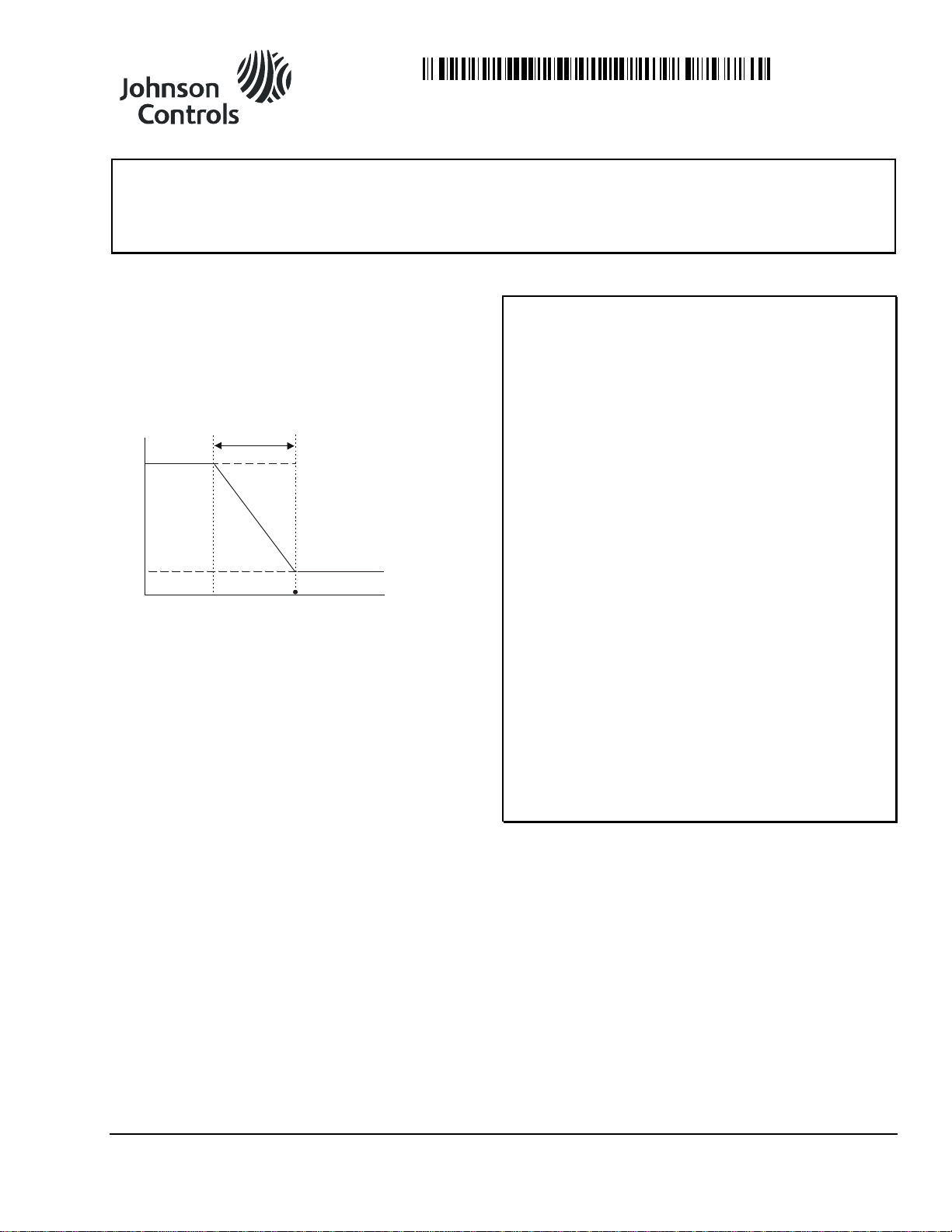
The HC-67x3 Humidity Controllers proportionally
ramp their output as the humidity changes in the
proportional band. The setpoint is at the low end of
the proportional band for Direct Acting (DA) and at
the high end for Reverse Acting (RA) (shown in
Figure 1) for both wall mount and duct probe
humidity controllers.
Figure 1: 0 to 10 Volt, RA Application
Configure the controller prior to installation for the
following: setpoint, proportional band, action, and
output signal. Proceed to the appropriate controller
section.
Installation
IMPORTANT: The HC-67x3 Series Humidity
Controllers is intended to provide an input to
equipment under normal operating conditions. Where
failure or malfunction of the HC-67x3 Series Humidity
Controllers could lead to personal injury or property
damage to the controlled equipment or other property,
additional precautions must be designed into the
control system. Incorporate and maintain other
devices, such as supervisory or alarm systems or
safety or limit controls, intended to warn of or protect
against failure or malfunction of the HC-67x3 Ser i es
Humidity Controllers.
IMPORTANT: Le HC-67x3 Series Humidity
Controllers est destiné à transmettre des données
entrantes à un équipement dans des conditions
normales de fonctionnement. Lorsqu'une défaillance
ou un dysfonctionnement du HC-67x3 Series Humidity
Controllers risque de provoquer des blessures ou
d'endommager l'équipement contrôlé ou un autre
équipement, la conception du système de contrôle doit
intégrer des dispositifs de protection supplémentaires.
Veiller dans ce cas à intégrer de façon permanente
d'autres dispositifs, tels que des systèmes de
supervision ou d'alarme, ou des dispositifs de sécurité
ou de limitation, ayant une fonction d'avertissement ou
de protection en cas de défaillance ou de
dysfonctionnement du HC-67x3 Series Humidity
Controllers.
The controller is available in both a wall mount or duct
probe package to suit a variety of sensing application
needs. Refer to the Mounting section for a complete list
of the tools required for installation.
Parts Included
• mounting base for U.S. wallbox or surface mounting
• No. 6-32 x 7/8 in. oval-head screw (2)
• No. 4-40 x 1/4 in. he x-head cover screw (in the
mounting base)
© 2016 Johnson Controls, Inc. 1
Part No. 24-7701-179, Rev. B www.johnsoncontrols.com
• drywall clip mounting kit (includes two each
No. 6-20 x 1.25 in. pan-head tapping screws, spring
clips, and spacers)
Page 2
Accessories
Product Code Number
Description
ACC-INSL-1*
Surface Mounting Pad (10/bag)
TE-67MB-600
Mounting Base Kit
** Contains 10 original style and 10 new style doors.
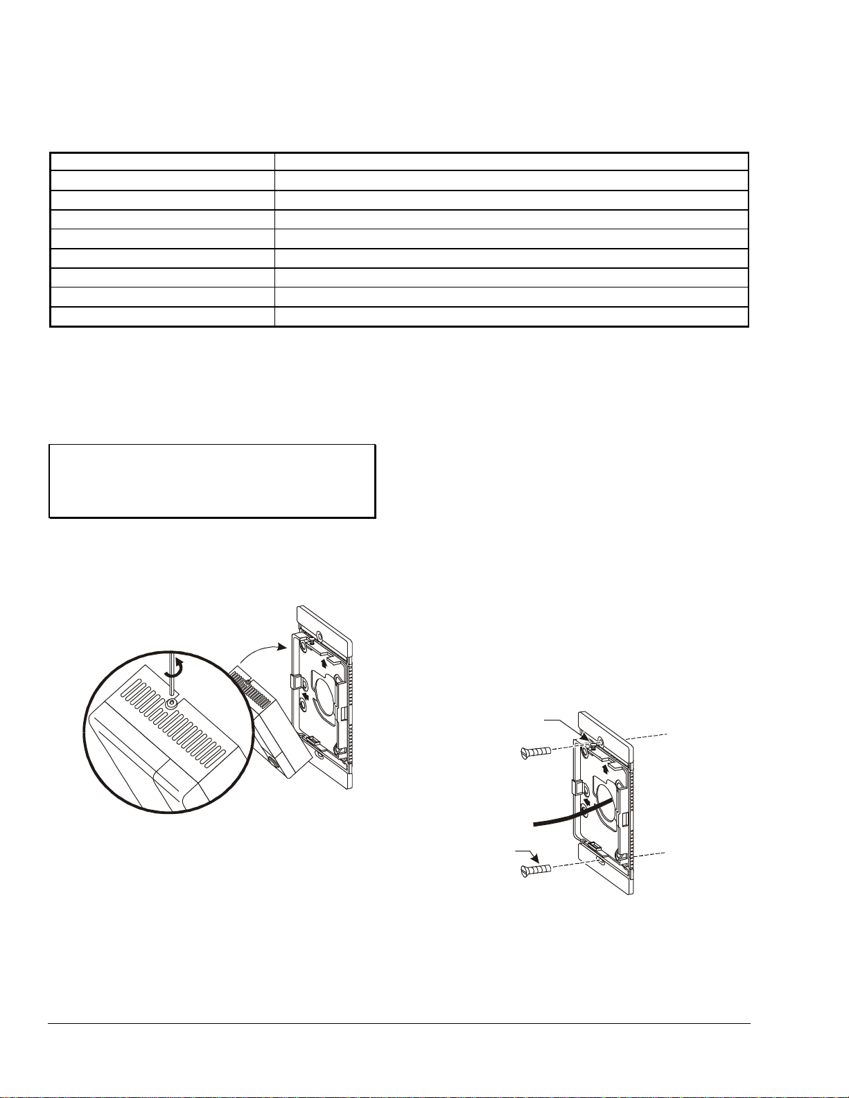
BaseCover
1. Loosen (do not
remove) the cover
screw with a 1/16 in.
(1.5 mm) Allen
wrench.
2. Swing the cover
down from the
base.
No. 6
Screws
Cover
Screw
Table 1: Accessories and Replacement Parts for the Wall Mount Humidity Controller
ACC-DWCLIP-0
ACC-INSL-0*
GRD10A-608
T-4000-119
TE-67D0-601**
TE-67D0-602**
* These foam pads help prevent drafts from entering the unit through the wall and make installation easier when mounting
on an uneven surface.
Drywall Clip Mounting Kit (10/bag)
Wallbox Mounting Pad (10/bag)
Plastic Guard with Baseplate and Mounting Ring
Allen-head Adjustment Tool (30/bag)
Door Replacement Kit with Johnson Controls logo
Door Replacement Kit without logo
Mounting
Location Considerations
IMPORTANT: To avoid damage to the
circuit board and components, do not mount the
unit in a location where high concentrations of
corrosive vapors are present.
The HC-67x3 controller is shipped with one
mounting base for both surface and wallbox
mounting. To mount the HC-67x3, release the cover
from the base as described in Figure 2.
be careful not to drop or mount the unit where it could be
exposed to excessive vibration. The following ambient
operating conditions apply:
• Temperature: 32 to 122°F (0 to 50°C)
• Humidity: 0 to 100% Relative Humidity (RH),
non-condensing; 85°F (29°C) maximum dew point
To mount the HC-67x3 to a wallbox:
1. Pull the cable or wiring through the wallbox and
base.
2. Rotate the mounting base, so one of the arrows on
the base points up.
Figure 2: Removing the Cover from the Base
Wallbox Mounting: Special Tools Needed
Use a 1/16 in. (1.5 mm) Allen wrench or
T-4000-119 Allen-head adjustment tool for
mounting.
Wallbox Mounting: Location Considerations
Locate the humidity transmitter on an inside wal l,
free from drafts, and out of direct sunlight. The
HC-67x3 is shock and vibration resistant; however,
2 TRUERH Series HC-67x3 Humidity Controllers Installation Instructions
3. Fasten the base to the wallbox with the
No. 6 screws provided. (See Figure 3.)
Note: These instructions assume a standard
2 x 4 in. (52 x 104 mm) U.S. wallbox is used.
Figure 3: Wallbox Mounting
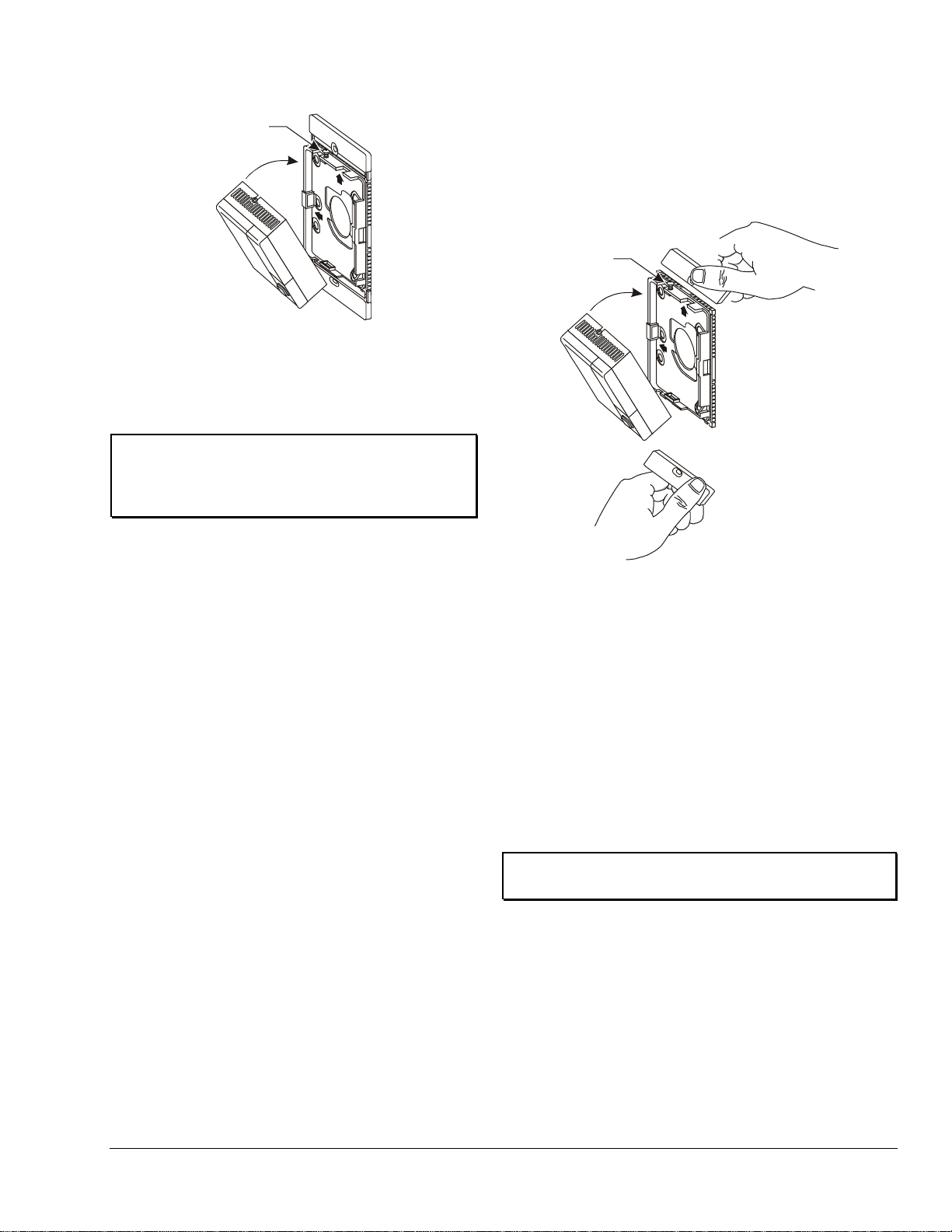
4. Place the bottom edge of the cover against the
bottom lip of the base, and rotate it up onto the
base. (See Figure 4.)
5. Tighten the cover screw.
Page 3
Base
Cover
Screw
Cover
Base
Cover
Screw
Cover
Figure 4: Attaching the Cover to the Base
Note: Once installed, the unit cannot be removed
from the wall unless the cover screw is loosened as
described in Figure 2.
IMPORTANT: Seal the drilled hole or use an
ACC-INSL-0 Foam Pad Kit to help reduce drafts
entering the unit. (See Table 1.) Drafts could result
in false readings.
needed as shown in Figure 6. Do not use the
spacers for 5/8 in. (16 mm) drywall.
Note: For replacement spring clips, spacers, and
screws, order the ACC-DWCLIP-0 Drywall Clip Mounting
Kit. (See Table 1.)
Surface Mounting: Special Tools Needed
• hole saw with 1-3/8 in. (35 mm) diameter blade
• 1/16 in. (1.5 mm) Allen wrench or
T-4000-119 Allen-head adjustment tool
• drill with 1/8 in. (3 mm ) drill b it
To mount the surface model to drywall, refer to
Figure 6 and proceed as follows:
1. Bend the top and bottom edges of mounting
base at the perforations until they break off.
(See Figure 5.)
2. Drill a 1-3/8 in. (35 mm) hole in the surface
where the unit is to be mounted, and pull the
wiring through the drilled hole.
3. Mark the location of the two mounting screws,
and drill the holes.
4. Insert the spring clips on each side of the drilled
1-3/8 in. (35 mm) hole, and use the spacers if
Figure 5: Removing the Breakaway Tabs
5. Pull the wiring through the base of the unit.
6. Center the two holes in the base over the two drilled
holes, and fasten the base to the drywall using the
No. 6 screws provided. (See Figure 6.)
7. Place the bottom edge of the cover against the
bottom lip of the base, and rotate it up onto the base
as shown in Figure 4.
8. Tighten the cover screw.
9. Once installed, the HE-67xx cannot be removed
from the wall unless the cover screw is loosened as
described in Figure 2.
IMPORTANT: To prevent drywall damage, do
not overtighten the screws.
TRUERH Series HC-67x3 Humidity Controllers Installation Instructions 3
Page 4

1-3/8 in.
(35 mm)
Hole
Drywall
Spacer (2) for
3/8 in. (9.5 mm) and 1/2 in.
(12.7 mm ) Thick Drywall
1-3/8 in.
(35 mm)
Hole
Spring
Clip (2)
Drywall
Drywall
Spring
Clip (2)
Base
No. 6-20 x 1.25 in.
Pan-head
Tapp ing Screw (2)
Duct Probe Humidity Controller: Parts Included
Housing
Conduit Hole
Snap-on Cover
Conduit Knockout
(Top and Bott om
of Cover)
Duct
Washer (Cup ped Side
Toward Housing)
Conduit Fitting
(Not Provided)
Nut for Conduit Fitting
(Not Provided)
No. 8
Screw
(2)
• HC-6703-6N00P duct probe humidity controller
• No. 8 x 1 in. Phillips-head sheet metal screw (2)
• washer for use with conduit fitting
Note: Conduit fitting and nut are not provided.
Duct Probe Humidity Controller:Special Tools Needed
• hole saw with 1 in. (25 mm) diameter blade
• drill with 1/8 in. (3 mm ) drill b it
• 1/8 in. (3 mm) flat-blade and No. 2 Phillips
screwdrivers
• pliers
• gasket, sealer, or other material to seal the area
between the unit and the duct
Duct Probe Mounting Location Considerations
Place the duct probe humidity controller in a location
that complies with the following:
• Position: Designed for duct mounting in any
position, except with the probe tip pointed up.
• Duct Diameter: Recommended minimum diameter
(round ducts) or width (square ducts) is 12 in.
(305 mm).
• Air Stratification (when the unit is mounted on the
discharge side of the fan): Recommended location
is at least 8 ft (2.4 m) downstream from the
humidification equipment, where duct air and
water vapor are sufficiently mixed. Avoid areas
where the probe may be exposed to condensation.
To mount the duct probe humidity controller, refer to
Figure 7, and proceed as follows:
1. Remove any excess insulation from the duct that
prevents the probe from extending a minimum of
3 in. (76 mm) into the air stream.
4 TRUERH Series HC-67x3 Humidity Controllers Installation Instructions
Figure 6: Surface Mounting to Drywall
2. Use the hole saw to make a 1 in. (25.4 mm) hole
in the duct for inserting the probe.
3. Pull the plastic cover off the housing.
Figure 7: Mounting and Assembly
4. Insert the probe into the duct, and mark the
location of the holes for the mounting screws.
5. Remove the unit, and drill a 1/8 in. (3 mm) hole for
each mounting screw.
IMPORTANT: Remove the unit before drilling
to prevent any metal remnants from falling onto the
circuit board. Seal any holes created during
installation to help reduce drafts and for more
accurate humidity readings.
6. Use a gasket, sealer, or other means to seal the
area around the 1 in. (25.4 mm) hole between the
unit and the duct.
7. Reinsert the probe, and secure the housing to the
duct using the two No. 8 screws provided.
Page 5

Wiring
!
Proportional
Band
Potentiometer
Output
Common
Power
20
15
10
5
2
6 to 9 VDC
0 to 10 VDC
(Factory Set)
Output
Reverse
(Factory Set)
Direct
Action
Setpoint
40
60
80
SP
20
Proportiona l Band
PB
5
2
20
15
10
Power
Ground (Common)
Output
Probe
Setpoint
Adjustment
Lever
Quick-mount
Installation Base
Pull Tab
Access Door
Manual Override
LED Dis play
CAUTION: Risk of Electric Shock.
Disconnect the power supply befor e m aking
electrical connections to avoid electric shock.
MISE EN GARDE: Risque de décharge électrique.
Débrancher l'alimentation avant de réaliser tout
raccordement électrique afin d'éviter tout risque de
décharge électrique.
Make all wiring connections using No. 18 AWG wire
and in accordance with the National Electrical Code
and all local regulations.
Wall Mount Humidity Controller
To wire the wall mount model, refer to Figure 8, and
proceed with the terminal connections.
Figure 9: Settings on a Duct Probe
Humidity Controller
Setup and Adjustments
Duct Probe Humidity Controller
To wire the duct probe model, refer to Figure 9, and
proceed as follows:
IMPORTANT: If using a conduit fitting
(not provided), use the washer provided to support
the fitting in the housing. If the washer is not used,
the fitting could stress the plastic housing.
1. Route the wires from the equipment to the unit
2. Break out the appropriate knockout from the
3. Press the cover onto the base.
Figure 8: Wiring and Proportional Band Setting
through the conduit hole in the housing shown in
Figure 7.
cover, shown in Figure 7, using pliers to
accommodate the wiring or conduit.
TRUERH Series HC-67x3 Humidity Controllers Installation Instructions 5
Wall Mount Humidity Controller
Setpoint
Adjust the setpoint using the setpoint adjustment lever
shown in Figure 10. To open the access door, push
down on the pull-tab, and pull the door open.
IMPORTANT: To prevent unauthorized
adjustment of the setpoint, install an optional plastic
guard. (See Table 1 for ordering information.)
Figure 10: Accessing the Setpoint
Page 6

Jumpers
Disengage the tabs
to remove the
circuit board.
Reverse
(Factory Set)
Direct
Action
0 to 10 VDC
(Factory Set)
6 to 9 VDC
Output
Circuit Bo ar d
Disengage the tabs
to remove the
circuit board.
Reverse
(Factory Set)
Direct
Action
0 to 10 VDC
(Factory Set)
6 to 9 VDC
Output
Circuit Bo ar d
To set the jumpers, refer to Figure 11. Turn the circuit
board over, and position the action and output jumpers
to suit the application. Reinstall the circuit board.
Figure 11: Jumper Settings
Proportional Band
To set the proportional band, see Figure 8. Use a
1/8 in. (3 mm) flat-blade screwdriver to turn the
potentiometer to the position desired.
Troubleshooting
If the humidity controller is not functioning properly:
1. Verify the unit is mounted in a location that is
indicative of space humidity (away from drafts and
sunlight, for example).
2. Check all supply voltage connections, and make
sure the wiring is correct. (Refer to Figure 8 and
Figure 9.)
3. Check the proportional band and setpoint settings.
If the humidity control equipment is cycling
excessively, the proportional band setting may be
too low.
4. Verify the jumper positions. If the unit is not
delivering an output, make sure the jumpers are
appropriately selected for the application.
5. Replace the unit if the troubleshooting suggestions
fail to remedy the problem.
Duct Probe Humidity Controller
Setpoint, Proportional Band, and Jumpers
Refer to Figure 9 to change the setpoint, proportional
band, or the action and output jumpers for the
application desired.
1. Use a 1/8 in. (3 mm) flat-blade screwdriver to turn
the setpoint or proportional band potentiometer to
the desired setting.
2. Select the appropriate control action and output
setting using the jumpers.
Repairs and Replacemen t
The HC-67x3 units are not field repairable. As with any
electrical device, keep the air vents clean and free
from dust or obstruction. The HC-67x3 controllers
have been designed for maintenance-free operation.
Sturdy packaging, solid-state components, and
high-quality element construction combine for a
long-lasting, high performance sensor. To order
replacement parts, contact the nearest
Johnson Controls representative.
6 TRUERH Series HC-67x3 Humidity Controllers Installation Instructions
Page 7

Technical Specifications
Product
T
RH Series HC-67x3 Humidity Controllers
Power Requirements
14 to 30 VDC at 10 mA or 20 to 30 VAC, 50/60 Hz at 15 mA with no load, Class 2
Control Action
Jumper selectable, direct or reverse (factory set for reverse acting)
Output Range
impedance
Proportional Band: Adjustable from 2 to 20% RH
Temperature Coefficient
-0.1 to 0.05% RH/°C at 5°C (41°F) to -0.07 to -0.21% RH/°C at 65°C (149°F)
Electrical Connections
3-position screw terminal block
Survival Operating
Ambient Storage
Conditions
-40 to 176°F (-40 to 80°C)
0 to 100% RH, non-condensing; 85°F (29°C) maximum dew point
Materials
Dimensions
Wall Moun t (H x W x D): 3.20 x 3.20 x 1.34 in. (81 x 81 x 34 mm)
Probe (L x D): 6.25 in. x 0.98 in. (159 mm x 25 mm)
European Single Point of Contact:
NA/SA Single Point of Contact:
APAC Single Point of Contact:
CHINA
Building Efficiency
Jumper selectable, 0 to 10 VDC (factory set) or 6 to 9 VDC; 5 k ohm minimum load
RUE
Humidity
Element: All-Polymer™ element
Sensing Range: 0 to 100% RH, non-condensing
Setpoint: Adjustable from 20 to 80% RH
Ambient Operating
Conditions
32 to 122°F (0 to 50°C)
0 to 100% RH, non-condensing; 85°F (29°C) maximum dew point
-22 to 140°F (-30 to 60°C)
Conditions
0 to 100% RH, non-condensing; 85°F (29°C) maximum dew point
Wall Mount: White plastic enclosure for surface or wallbox mounting, including
hardware
Duct Probe: Light gray plastic cover with dark gray plastic housing and probe
Duct Probe (H x W x D): 3.25 in. x 3.25 in. x 8.27 in. (83 mm x 83 mm x 210 mm)
Shipping Weight
Agency Compliance
The performance specifications are nominal and conform to acceptable industry standards. For application at conditions beyond these
specifications, consult the local Johnson Controls office. Johnson Controls, Inc. shall not be liable for damages result i ng from misapplic ation or
misuse of its products.
0.7 lb (0.3 kg)
Duct Probe Material: 94-5 V flammability rated per UL 94
JOHNSON CONTROLS
WESTENDHOF 3
45143 ESSEN
GERMANY
JOHNSON CONTROLS
507 E MICHIGAN ST
MILWAUKEE WI 53202
USA
JOHNSON CONTROLS
C/O CONTROLS PRODUCT
MANAGEMENT
NO. 22 BLOCK D NEW DISTRICT
WUXI JIANGSU PROVINCE 214142
507 E. Michigan Street, Milwaukee, WI 53202
Metasys® and Johnson Controls® are registered trademarks of Johnson Controls, Inc.
All other marks herein are the marks of their respective owners. © 2016 Johnson Controls, Inc.
TRUERH Series HC-67x3 Humidity Controllers Installation Instructions 7
 Loading...