


INSTALLATION MANUAL
RESIDENTIAL GAS FURNACE MODELS TG8S*MP, TGLS*MP, GG8S*MP, GGLS*MP (Single Stage Multi-position / Low NOx)
LIST OF SECTIONS
SAFETY . . . . . . . . . . . . . . . . . . . . . . . . . . . . . . . . . . . . . . . . . . . . . . . 1 DUCTWORK . . . . . . . . . . . . . . . . . . . . . . . . . . . . . . . . . . . . . . . . . . . 5 FILTERS . . . . . . . . . . . . . . . . . . . . . . . . . . . . . . . . . . . . . . . . . . . . . . 9 GAS PIPING . . . . . . . . . . . . . . . . . . . . . . . . . . . . . . . . . . . . . . . . . . 10 ELECTRICAL POWER . . . . . . . . . . . . . . . . . . . . . . . . . . . . . . . . . . 12 TWINNING AND STAGING . . . . . . . . . . . . . . . . . . . . . . . . . . . . . . . 15
VENT SYSTEM . . . . . . . . . . . . . . . . . . . . . . . . . . . . . . . . . . . . . . . . 16 START-UP AND ADJUSTMENTS . . . . . . . . . . . . . . . . . . . . . . . . . . 19 SAFETY CONTROLS . . . . . . . . . . . . . . . . . . . . . . . . . . . . . . . . . . . 26 REPLACEMENT PARTS LIST . . . . . . . . . . . . . . . . . . . . . . . . . . . . 28 REPLACEMENT PART CONTACT INFORMATION . . . . . . . . . . . . 28 WIRING DIAGRAM . . . . . . . . . . . . . . . . . . . . . . . . . . . . . . . . . . . . . 29
LIST OF FIGURES
Duct Attachment . . . . . . . . . . . . . . . . . . . . . . . . . . . . . . . . . . . . . . . . . 5 Vertical Applications . . . . . . . . . . . . . . . . . . . . . . . . . . . . . . . . . . . . . . 6 Coil Flange . . . . . . . . . . . . . . . . . . . . . . . . . . . . . . . . . . . . . . . . . . . . . 6 Horizontal Right Application . . . . . . . . . . . . . . . . . . . . . . . . . . . . . . . . 6 Horizontal Left Application . . . . . . . . . . . . . . . . . . . . . . . . . . . . . . . . . 6 PC Series Upflow Coil Installation . . . . . . . . . . . . . . . . . . . . . . . . . . . 7 Horizontal Left or Right application (Right Shown) . . . . . . . . . . . . . . 7 Combustible Floor Base Accessory . . . . . . . . . . . . . . . . . . . . . . . . . . 7 Horizontal Application . . . . . . . . . . . . . . . . . . . . . . . . . . . . . . . . . . . . 7 Typical Attic Installation . . . . . . . . . . . . . . . . . . . . . . . . . . . . . . . . . . . 8 Typical Suspended Furnace / Crawl Space Installation . . . . . . . . . . . 8 Dimensions . . . . . . . . . . . . . . . . . . . . . . . . . . . . . . . . . . . . . . . . . . . . 9 Side Return Cutout Markings . . . . . . . . . . . . . . . . . . . . . . . . . . . . . . 10 Gas Valve . . . . . . . . . . . . . . . . . . . . . . . . . . . . . . . . . . . . . . . . . . . . . 10 Gas Piping . . . . . . . . . . . . . . . . . . . . . . . . . . . . . . . . . . . . . . . . . . . . 10
Electrical Wiring . . . . . . . . . . . . . . . . . . . . . . . . . . . . . . . . . . . . . . . . 12
Thermostat Chart - Single Stage AC with
Single Stage PSC Furnaces . . . . . . . . . . . . . . . . . . . . . . . . . . . . . . . 13
Thermostat Chart - Single Stage HP with
Single Stage PSC Furnaces . . . . . . . . . . . . . . . . . . . . . . . . . . . . . . . 14 Typical Twinned Furnace Application . . . . . . . . . . . . . . . . . . . . . . . . 15 Single Wire Twinning Wiring Diagram . . . . . . . . . . . . . . . . . . . . . . . 16 Single Wire Staging Wiring Diagram . . . . . . . . . . . . . . . . . . . . . . . . 16 Combustion Air Inducer . . . . . . . . . . . . . . . . . . . . . . . . . . . . . . . . . . 16
Combustion Airflow Path Through The Furnace
Casing to the Burner Compartment . . . . . . . . . . . . . . . . . . . . . . . . . 17 Outside and Ambient Combustion Air . . . . . . . . . . . . . . . . . . . . . . . . 18 Gas Valve . . . . . . . . . . . . . . . . . . . . . . . . . . . . . . . . . . . . . . . . . . . . . 22 Reading Gas Pressure . . . . . . . . . . . . . . . . . . . . . . . . . . . . . . . . . . . 22 Furnace Control Board . . . . . . . . . . . . . . . . . . . . . . . . . . . . . . . . . . . 23 Wiring Diagram . . . . . . . . . . . . . . . . . . . . . . . . . . . . . . . . . . . . . . . . . 29
LIST OF TABLES
Unit Clearances to Combustibles . . . . . . . . . . . . . . . . . . . . . . . . . . . . 4 Coil Projection Dimensions - PC Series Coils . . . . . . . . . . . . . . . . . . 7 Cabinet and Duct Dimensions . . . . . . . . . . . . . . . . . . . . . . . . . . . . . . 9 Recommended Filter Sizes (High Velocity 600 FPM) . . . . . . . . . . . . 9 Nominal Manifold Pressure . . . . . . . . . . . . . . . . . . . . . . . . . . . . . . . 11 Ratings & Physical / Electrical Data . . . . . . . . . . . . . . . . . . . . . . . . . 12 Estimated Free Area . . . . . . . . . . . . . . . . . . . . . . . . . . . . . . . . . . . . 17 Unconfined Space Minimum Area . . . . . . . . . . . . . . . . . . . . . . . . . . 18
Free Area . . . . . . . . . . . . . . . . . . . . . . . . . . . . . . . . . . . . . . . . . . . . . 18 Gas Rate (CU FT/HR) . . . . . . . . . . . . . . . . . . . . . . . . . . . . . . . . . . . 21 Inlet Gas Pressure Range . . . . . . . . . . . . . . . . . . . . . . . . . . . . . . . . 22 Nominal Manifold Pressure . . . . . . . . . . . . . . . . . . . . . . . . . . . . . . . . 22
Blower Performance CFM - Any Position
(without filter) - Bottom Return . . . . . . . . . . . . . . . . . . . . . . . . . . . . . 24
Blower Performance CFM - Any Position
(without filter) - Left Side Return . . . . . . . . . . . . . . . . . . . . . . . . . . . . 25
These high efficiency, compact units employ induced combustion, reliable hot surface ignition and high heat transfer aluminized tubular heat exchangers. The units are factory shipped for installation in upflow or horizontal applications and may be converted for downflow applications.
These furnaces are designed for residential installation in a basement, closet, alcove, attic, recreation room or garage and are also ideal for commercial applications. All units are factory assembled, wired and tested to assure safe dependable and economical installation and operation.
These units are Category I listed and may be common vented with another gas appliance as allowed by the National Fuel Gas Code.
SECTION I: SAFETY
This is a safety alert symbol. When you see this symbol on labels or in manuals, be alert to the potential for personal
injury.
Understand and pay particular attention to the signal words DANGER,
WARNING, or CAUTION.
DANGER indicates an imminently hazardous situation, which, if not avoided, will result in death or serious injury.
WARNING indicates a potentially hazardous situation, which, if not avoided, could result in death or serious injury.
CAUTION indicates a potentially hazardous situation, which, if not avoided may result in minor or moderate injury. It is also used to alert against unsafe practices and hazards involving only property damage.
Improper installation may create a condition where the operation of the product could cause personal injury or property damage.
Improper installation, adjustment, alteration, service or maintenance can cause injury or property damage. Failure to carefully read and follow all instructions in this manual can result in furnace malfunction, death, personal injury and/or property damage. Only a qualified contractor, installer or service agency should install this product.
356485-UIM-G-1211
356485-UIM-G-1211
SPECIFIC SAFETY RULES AND PRECAUTIONS
1.Only Natural gas or Propane (LP) gas are approved for use with this furnace.
2.Install this furnace only in a location and position as specified in these instructions.
3.A gas-fired furnace for installation in a residential garage must be installed as specified in these instructions.
4.Provide adequate combustion and ventilation air to the furnace space as specified in these instructions.
5.Combustion products must be discharged outdoors. Connect this furnace to an approved vent system only, as specified in SECTION VII of these instructions.
6.Test for gas leaks as specified in these instructions.
FIRE OR EXPLOSION HAZARD
Failure to follow the safety warnings exactly could result in serious injury, death or property damage.
Never test for gas leaks with an open flame. Use a commercially available soap solution made specifically for detection of leaks to check all connections. A fire or explosion may result causing property damage, personal injury or loss of life.
7.Always install the furnace to operate within the furnace’s intended temperature rise range. Only connect the furnace to a duct system which has an external static pressure within the allowable range, as specified on the furnace rating plate.
8.When a furnace is installed so that supply ducts carry air circulated by the furnace to areas outside the space containing the furnace, the return air shall also be handled by duct(s) sealed to the furnace casing and terminating outside the space containing the furnace.
9.It is permitted to use the furnace for heating of buildings or structures under construction where the application and use must comply with all manufacturer’s installation instructions including:
•Proper vent installation;
•Furnace operating under thermostatic control;
•Return air duct sealed to the furnace;
•Air filters in place;
•Set furnace input rate and temperature rise per rating plate marking;
•Means for providing outdoor air required for combustion;
•Return air temperature maintained between 55ºF (13ºC) and 80ºF (27ºC);
•The air filter must be replaced upon substantial completion of the construction process;
•Clean furnace, duct work and components upon substantial completion of the construction process, and verify furnaceoperating conditions including ignition, input rate, temperature rise and venting, according to the manufacturer’s instructions.
10.When installed in a Non-HUD-Approved Modular Home or building constructed on-site, combustion air shall not be supplied from occupied spaces.
11.The size of the unit should be based on an acceptable heat loss calculation for the structure. ACCA, Manual J or other approved methods may be used.
12.When moving or handling this furnace prior to installation it is recommended to leave the doors on the furnace to provide support and to prevent damage or warping of the cabinet. When lifting the furnace by the cabinet, support the ends of the furnace rather than lifting by the cabinet flanges at the return air openings (bottom or sides) or supply air opening.
13.When lifting the furnace, it is acceptable to use the primary heat exchanger tubes as a lifting point provided that the tubes are lifted at the front of the heat exchangers where attached to the vestibule panel. Do not use the top return bend of the heat exchangers as lifting points as the tubes may shift out of position or their location brackets/baffles.
During installation, doors should remain on the furnace when moving or lifting.
SAFETY REQUIREMENTS
This product must be installed in strict compliance with the installation instructions and any applicable local, state, and national codes including, but not limited to building, electrical, and mechanical codes.
•Refer to the unit rating plate for the furnace model number, and then see the dimensions page of this instruction for return air plenum dimensions in Figure 12. The plenum must be installed according to the instructions.
•Provide clearances from combustible materials as listed under Clearances to Combustibles.
•Provide clearances for servicing ensuring that service access is allowed for both the burners and blower.
•These models ARE NOT CSA listed or approved for installation into a HUD Approved Modular Home or a Manufactured (Mobile) Home.
•This furnace is not approved for installation in trailers or recreational vehicles.
•Furnaces for installation on combustible flooring shall not be installed directly on carpeting, tile or other combustible material other than wood flooring.
•Check the rating plate and power supply to be sure that the electrical characteristics match. All models use nominal 115 VAC, 1 Phase, 60-Hertz power supply. DO NOT CONNECT THIS APPLIANCE TO A 50 HZ POWER SUPPLY OR A VOLTAGE ABOVE 130 VOLTS.
•Furnace shall be installed so the electrical components are protected from water.
•Installing and servicing heating equipment can be hazardous due to the electrical components and the gas fired components. Only trained and qualified personnel should install, repair, or service gas heating equipment. Untrained service personnel can perform basic maintenance functions such as cleaning and replacing the air filters. When working on heating equipment, observe precautions in the manuals and on the labels attached to the unit and other safety precautions that may apply.
2 |
Johnson Controls Unitary Products |
356485-UIM-G-1211
COMBUSTION AIR QUALITY
(LIST OF CONTAMINANTS)
The furnace requires OUTDOOR AIR for combustion when the furnace is located in any of the following environments.
•Restricted Environments
•Commercial buildings
•Buildings with indoor pools
•Furnaces installed in laundry rooms
•Furnaces installed in hobby or craft rooms
•Furnaces installed near chemical storage areas
•Chemical exposure
The furnace requires OUTDOOR AIR for combustion when the furnace is located in an area where the furnace is being exposed to the following substances and / or chemicals.
•Permanent wave solutions
•Chlorinated waxes and cleaners
•Chlorine based swimming pool chemicals
•Water softening chemicals
•De-icing salts or chemicals
•Carbon tetrachloride
•Halogen type refrigerants
•Cleaning solvents (such as perchloroethylene)
•Printing inks, paint removers, varnishes, etc.
•Hydrochloric acid
•Cements and glues
•Antistatic fabric softeners for clothes dryers
•Masonry acid washing materials
When outdoor air is used for combustion, the combustion air intake duct system termination must be located external to the building and in an area where there will be no exposure to the substances listed above.
The furnace area must not be used as a broom closet or for any other storage purposes, as a fire hazard may be created. Never store items such as the following on, near or in contact with the furnace.
1.Spray or aerosol cans, rags, brooms, dust mops, vacuum cleaners or other cleaning tools.
2.Soap powders, bleaches, waxes or other cleaning compounds; plastic items or containers; gasoline, kerosene, cigarette lighter fluid, dry cleaning fluids or other volatile fluid.
3.Paint thinners and other painting compounds.
4.Paper bags, boxes or other paper products
Never operate the furnace with the blower door removed. To do so could result in serious personal injury and/or equipment damage.
CODES AND STANDARDS
Follow all national, local codes and standards in addition to this installation manual. The installation must comply with regulations of the serving gas supplier, local building, heating, plumbing, and other codes. In absence of local codes, the installation must comply with the national codes listed below and all authorities having jurisdiction.
In the United States and Canada, follow all codes and standards for the following, using the latest edition available:
STEP 1 -Safety
•US: National Fuel Gas Code (NFGC) NFPA 54/ANSI Z223.1 and the Installation Standards, Warm Air Heating and Air Conditioning Systems ANSI/NFPA 90B
•CANADA: CAN/CGA-B149.1 National Standard of Canada. Natural Gas and Propane Installation Codes (NSCNGPIC)
STEP 2 -General Installation
•US: Current edition of the NFGC and NFPA 90B. For copies, contact the
National Fire Protection Association Inc. Batterymarch Park
Quincy, MA 02269
or for only the NFGC, contact the American Gas Association, 400 N. Capital, N.W. Washington DC 20001
or www.NFPA.org
•CANADA: NSCNGPIC. For a copy contact:
Standard Sales, CSA International
178 Rexdale Boulevard
Etobicoke, (Toronto) Ontario Canada M9W 1RS
STEP 3 -Combustion and Ventilation Air
•US: Section 5.3 of the NFGC, air for Combustion and Ventilation
•CANADA: Part 7 of NSCNGPIC, Venting Systems and Air Supply for Appliances
STEP 4 -Duct Systems
•US and CANADA: Air Conditioning Contractors Association (ACCA) Manual D, Sheet Metal and Air Conditioning Contractors Association National Association (SMACNA), or American Society of Heating, Refrigeration, and Air Conditioning Engineers (ASHRAE) 1997 Fundamentals Handbook Chapter 32.
STEP 5 -Acoustical Lining and Fibrous Glass Duct
•US and CANADA: Current edition of SMACNA and NFPA 90B as tested by UL Standard 181 for Class I Rigid Air Ducts
STEP 6 -Gas Piping and Gas Pipe Pressure Testing
•US: NFGC; chapters 2, 3, 4, & 9 and National Plumbing Codes
•CANADA: NSCNGPIC Part 5
STEP 7 -Electrical Connections
•US: National Electrical Code (NEC) ANSI/NFPA 70
•CANADA: Canadian Electrical Code CSA C22.1
These instructions cover minimum requirements and conform to existing national standards and safety codes. In some instances these instructions exceed certain local codes and ordinances, especially those who have not kept up with changing residential and non-HUD modular home construction practices. These instructions are required as a minimum for a safe installation.
Johnson Controls Unitary Products |
3 |
356485-UIM-G-1211
FOR FURNACES INSTALLED IN THE COMMONWEALTH OF MASSACHUSETTS ONLY
For all side wall horizontally vented gas fueled equipment installed in every dwelling, building or structure used in whole or in part for residential purposes, including those owned or operated by the Commonwealth and where the side wall exhaust vent termination is less than seven (7) feet above finished grade in the area of the venting, including but not limited to decks and porches, the following requirements shall be satisfied:
1.INSTALLATION OF CARBON MONOXIDE DETECTORS. At the time of installation of the side wall horizontal vented gas fueled equipment, the installing plumber or gasfitter shall observe that a hard wired carbon monoxide detector with an alarm and battery back-up is installed on the floor level where the gas equipment is to be installed. In addition, the installing plumber or gasfitter shall observe that a battery operated or hard wired carbon monoxide detector with an alarm is installed on each additional level of the dwelling, building or structure served by the side wall horizontal vented gas fueled equipment. It shall be the responsibility of the property owner to secure the services of qualified licensed professionals for the installation of hard wired carbon monoxide detectors
a.In the event that the side wall horizontally vented gas fueled equipment is installed in a crawl space or an attic, the hard wired carbon monoxide detector with alarm and battery back-up may be installed on the next adjacent floor level.
b.In the event that the requirements of this subdivision can not be met at the time of completion of installation, the owner shall have a period of thirty (30) days to comply with the above requirements; provided, however, that during said thirty (30) day period, a battery operated carbon monoxide detector with an alarm shall be installed.
2.APPROVED CARBON MONOXIDE DETECTORS. Each carbon monoxide detector as required in accordance with the above provisions shall comply with NFPA 720 and be ANSI/UL 2034 listed and IAS certified.
3.SIGNAGE. A metal or plastic identification plate shall be permanently mounted to the exterior of the building at a minimum height of eight (8) feet above grade directly in line with the exhaust vent terminal for the horizontally vented gas fueled heating appliance or equipment. The sign shall read, in print size no less than one-half (1/2) inch in size, "GAS VENT
DIRECTLY BELOW. KEEP CLEAR OF ALL OBSTRUCTIONS".
4.INSPECTION. The state or local gas inspector of the side wall horizontally vented gas fueled equipment shall not approve the installation unless, upon inspection, the inspector observes carbon monoxide detectors and signage installed in accordance with the provisions of 248 CMR 5.08(2)(a)1 through 4.
INSPECTION
As soon as a unit is received, it should be inspected for possible damage during transit. If damage is evident, the extent of the damage should be noted on the carrier’s freight bill. A separate request for inspection by the carrier’s agent should be made in writing. Also, before installation, the unit should be checked for screws or bolts which may have loosened in transit. There are no shipping or spacer brackets which need to be removed from the interior of this unit.
FURNACE LOCATION AND CLEARANCES
The furnace shall be located using the following guidelines:
1.Where a minimum amount of air intake/vent piping and elbows will be required.
2.As centralized with the air distribution as possible.
3.Where adequate combustion air will be available (particularly when the appliance is not using outdoor combustion air).
4.Where it will not interfere with proper air circulation in the confined space.
Installation in freezing temperatures:
1.Furnace shall be installed in an area where ventilation facilities provide for safe limits of ambient temperature under normal operating conditions.
Improper installation in an ambient below 32ºF (0.0° C) could create a hazard, resulting in damage, injury or death.
2.Do not allow return air temperature to be below 55º F (13° C) for extended periods. To do so may cause condensation to occur in the main heat exchanger, leading to premature heat exchanger failure.
Clearances for access/service:
Ample clearances should be provided to permit easy access to the unit. The following minimum clearances are recommended:
1.Twenty-four (24) inches (61 cm) between the front of the furnace and an adjacent wall or another appliance, when access is required for servicing and cleaning.
2.Eighteen (18) inches (46 cm) at the side where access is required for passage to the front when servicing or for inspection or replacement of flue/vent connections.
In all cases, accessibility clearances shall take precedence over clearances for combustible materials where accessibility clearances are greater.
Installation in a residential garage:
A gas-fired furnace for installation in a residential garage must be installed so the burner(s) and the ignition source are located not less than 18 inches (46 cm) above the floor, and the furnace must be located or protected to avoid physical damage by vehicles.
Table 1: Unit Clearances to Combustibles (All Dimensions in Inches, and All Surfaces Identified with the Unit in an Upflow Configuration) |
|
|||||||||||
|
|
|
|
|
|
|
|
|
|
|
|
|
Application |
Top |
Front |
Rear |
Left Side |
Right Side |
Flue |
Floor/ |
Closet |
Alcove |
Attic |
|
Line |
In. (cm) |
In. (cm) |
In. (cm) |
In. (cm) |
In. (cm) |
In. (cm) |
Bottom |
|
Contact |
||||
|
|
|
|
|
||||||||
Upflow |
1 (2.5) |
1 (2.5) |
0 (0.0) |
0 (0.0) |
0 (0.0) |
6 (15.2) |
Combustible |
Yes |
Yes |
Yes |
|
No |
Upflow B-Vent |
1 (2.5) |
1 (2.5) |
0 (0.0) |
0 (0.0) |
0 (0.0) |
1 (2.5) |
Combustible |
Yes |
Yes |
Yes |
|
No |
Downflow |
1 (2.5) |
1 (2.5) |
0 (0.0) |
0 (0.0) |
0 (0.0) |
6 (15.2) |
1 (25.4)1 |
Yes |
Yes |
Yes |
|
No |
Downflow B-Vent |
1 (2.5) |
1 (2.5) |
0 (0.0) |
0 (0.0) |
0 (0.0) |
1 (2.5) |
1 (25.4)1 |
Yes |
Yes |
Yes |
|
No |
Horizontal |
1 (2.5) |
1 (2.5) |
0 (0.0) |
0 (0.0) |
0 (0.0) |
6 (15.2) |
Combustible |
No |
Yes |
Yes |
|
Yes2 |
Horizontal B-Vent |
1 (2.5) |
1 (2.5) |
0 (0.0) |
0 (0.0) |
0 (0.0) |
1 (2.5) |
Combustible |
No |
Yes |
Yes |
|
Yes2 |
1.Special floor base or air conditioning coil required for use on combustible floor.
2.Line contact only permitted between lines formed by the intersection of the rear panel and side panel (top in horizontal position) of the furnace jacket and building joists, studs or framing.
4 |
Johnson Controls Unitary Products |
356485-UIM-G-1211
SECTION II: DUCTWORK
DUCTWORK GENERAL INFORMATION
The duct system’s design and installation must:
1.Handle an air volume appropriate for the served space and within the operating parameters of the furnace specifications.
2.Be installed in accordance of National Fire Protection Association as outlined in NFPA standard 90B (latest editions) or applicable national, provincial, state, and local fire and safety codes.
3.Create a closed duct system. For residential and Non-HUD Modular Home installations, when a furnace is installed so that the supply ducts carry air circulated by the furnace to areas outside the space containing the furnace, the return air shall also be handled by a duct(s) sealed to the furnace casing and terminating outside the space containing the furnace.
4.Complete a path for heated or cooled air to circulate through the air conditioning and heating equipment and to and from the conditioned space.
The cooling coil must be installed in the supply air duct, downstream of the furnace. Cooled air may not be passed over the heat exchanger.
When the furnace is used with a cooling coil, the coil must be installed parallel with, or in the supply air side of the furnace to avoid condensation in the primary heat exchanger. When a parallel flow arrangement is used, dampers or other means used to control airflow must be adequate to prevent chilled air from entering the furnace. If manually operated, the damper must be equipped with means to prevent the furnace or the air conditioner from operating unless the damper is in full heat or cool position.
When replacing an existing furnace, if the existing plenum is not the same size as the new furnace then the existing plenum must be removed and a new plenum installed that is the proper size for the new furnace. If the plenum is shorter than 12” (30.5 cm) the turbulent air flow may cause the limit controls not to operate as designed, or the limit controls may not operate at all.
The duct system is a very important part of the installation. If the duct system is improperly sized the furnace will not operate properly.
The ducts attached to the furnace plenum, should be of sufficient size so that the furnace operates at the specified external static pressure and within the air temperature rise specified on the nameplate.
The minimum plenum height is 12” (30.5 cm). The furnace will not operate properly on a shorter plenum height. The minimum recommended rectangular duct height is 4 inches (10 cm) attached to the plenum.
The duct system must be properly sized to obtain the correct airflow for the furnace size that is being installed.
Refer to Table 6 or the furnace rating plate for the correct rise range and static pressures.
If the ducts are undersized, the result will be high duct static pressures and/or high temperature rises which can result in a heat exchanger OVERHEATING CONDITION. This condition can result in premature heat exchanger failure, which can result in personal injury, property damage, or death.
If a matching cooling coil is used, it may be placed directly on the furnace outlet and sealed to prevent leakage. If thermoplastic evaporator ‘A’ coil drain pans are to be installed in the upflow/horizontal configuration, then extra 2” minimum spacing may be needed to ensure against drain pan distortion.
On all installations without a coil, a removable access panel is recommended in the outlet duct such that smoke or reflected light would be observable inside the casing to indicate the presence of leaks in the heat exchanger. This access cover shall be attached in such a manner as to prevent leaks.
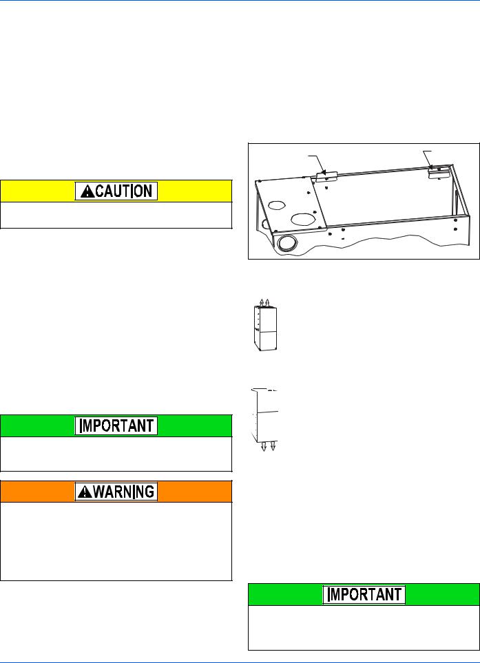
DUCT FLANGES
Four flanges are provided to attach ductwork to the furnace. These flanges are rotated down for shipment. In order to use the flanges, remove the screw holding an individual flange, rotate the flange so it is in the upward position and reinstall the screw then repeat this for all 4 flanges.
If the flanges are not used, they must remain in the rotated down position as shipped.
For duct attachment, |
Factory |
if needed. |
installed |
FIGURE 1: Duct Attachment
DUCTWORK INSTALLATION AND SUPPLY PLENUM CONNECTION - UPFLOW/HORIZONTAL
Attach the supply plenum to the furnace outlet. The use of
an approved flexible duct connector is recommended on all
installations. This connection should be sealed to prevent
air leakage. The sheet metal should be crosshatched to eliminate any popping of the sheet metal when the indoor
fan is energized.
FLOOR BASE AND DUCTWORK INSTALLATION - DOWNFLOW
Installations on combustible material or directly on any floors must use a combustible floor base shown in Figure 8.
Follow the instructions supplied with the combustible floor base accessory. This combustible floor base can be replaced with a matching cooling coil, properly sealed to
prevent leaks. Follow the instructions supplied with the
cooling coil cabinet for installing the cabinet to the duct con-
nector. Plug intake and vent pipe holes in bottom panel and move grommet to desired vent side exit.
Downflow Air Conditioning Coil Cabinet
The furnace should be installed with coil cabinet part number specifically intended for downflow application. If a matching cooling coil is used, it may be placed directly on the furnace outlet and sealed to prevent leakage. For details of the coil cabinet dimensions and installation requirements, refer to the installation instructions supplied with the coil cabinet.
Attach the air conditioning coil cabinet to the duct connector, and then position the furnace on top of the coil cabinet. The connection to the furnace, air conditioning coil cabinet, duct connector, and supply air duct must be sealed to prevent air leakage.
COIL INSTALLATION
On all installations without a coil, a removable access panel is recommended in the outlet duct such that smoke or reflected light would be observable inside the casing to indicate the presence of leaks in the heat exchanger. This access cover shall be attached in such a manner as to prevent leaks.
Johnson Controls Unitary Products |
5 |

356485-UIM-G-1211
COIL/FURNACE ASSEMBLY - MC/FC/PC SERIES COILS
|
Furnace |
Furnace |
|
UPFLOW |
DOWNFLOW |
FIGURE 2: Vertical Applications
FURNACE ASSEMBLY - MC & FC SERIES COILS
These coils are factory shipped for installation in either upflow or downflow applications with no conversion.
Position the coil casing over or under the furnace opening as shown in Figure 2 after configuring coil flanges as required see “Coil Flange” section below.
COIL FLANGE INSTALLATION
The coils include removable flanges to allow proper fit up with furnaces having various inlet and outlet flange configurations. The two flanges are attached to the top of the coil in the factory during production. For proper configuration of flanges refer to Figure 3.
|
FACTORY |
|
FLANGE |
|
LOCATION |
|
(Used for upflow |
|
or horizontal |
ALTERNATE |
right installations) |
|
|
FLANGE LOCATION |
|
(Used for downflow or |
|
horizontal left installations) |
|
FIGURE 3: Coil Flange
FURNACE ASSEMBLY - MC SERIES COILS ONLY
MC coils are supplied ready to be installed in a horizontal position. A horizontal pan is factory installed. MC coils should be installed in all horizontal applications with the horizontal drain pan side down.
Mounting Plate |
Furnace |
FIGURE 4: Horizontal Right Application
For horizontal left hand applications no conversion is required to an MC coil when used with a downflow/horizontal furnace. A mounting plate, supplied with every coil should always be installed on the side designated as top side. See Figures 4 & 5.
Mounting Plate |
Furnace |
FIGURE 5: Horizontal Left Application
FURNACE ASSEMBLY - PC SERIES COILS
These upflow coils are designed for installation on top of upflow furnaces only.
If the coil is used with a furnace of a different size, use a 45° transition to allow proper air distribution through the coil.
1.Position the coil casing over the furnace opening as shown in Figure 6.
2.Place the ductwork over the coil casing flange and secure.
3.Check for air leakage between the furnace and coil casing and seal appropriately.
Do not drill any holes or drive any screws into the front duct flange on the coil in order to prevent damaging coil tubing. See Figure 6
C
D (Min) |
|
|
Flexible |
|
Duct Collar |
Field |
|
Fabricated |
|
Ductwork |
Do not drill |
|
or Screw |
Upflow |
this flange |
Coil |
|
Upflow |
Furnace |
|
Primary |
Secondary |
Alternate |
||
|
Drain |
Drain Location |
|||
|
|
Drain |
|||
|
|
|
|
|
|
|
|
|
|
|
|
FIGURE 6: PC Series Upflow Coil Installation |
|
|
|||
|
Table 2: Coil Projection Dimensions - PC Series Coils |
||||
|
|
|
|
|
|
|
COIL SIZE |
|
DIMENSION “C” INCH |
|
|
|
|
|
|
|
|
|
PC18 |
|
|
3-1/2 |
|
|
PC24 |
|
|
4-1/2 |
|
|
PC30, PC32, PC35 |
|
|
4-1/2 |
|
|
PC42, PC43, PC36, PC37 |
|
|
5-1/2 |
|
|
PC48 |
|
|
6-1/2 |
|
|
PC60 |
|
|
9 |
|
Dimension “C” should be at least 2/3 of dimension “D”. See Figure 6
6 |
Johnson Controls Unitary Products |
356485-UIM-G-1211
CRITICAL COIL PROJECTION
The coil assembly must be located in the duct such that a minimum distance is maintained between the top of the coil and the top of the duct. Refer to Table 2.
COIL / FURNACE ASSEMBLY - HC SERIES COILS
These coils are supplied ready to be installed in a right hand position or a left hand position. When used in conjunction with a horizontal furnace (blow through) application, the coil should be oriented with the opening of the “A” coil closest to the furnace. See Figure 7.
NOTICE
Each coil is shipped with an external tie plate that should be used to secure the coil to the furnace. It should be installed on the back side of the coil using the dimpled pilot holes. See Figure 7.
Use tie plate |
supplied with coil |
Gas Furnace |
flow |
FIGURE 7: Horizontal Left or Right application (Right Shown)
DOWNFLOW DUCT CONNECTORS
All downflow installations must use a suitable duct connector approved by the furnace manufacturer for use with this furnace. The duct connectors are designed to be connected to the rectangular duct under the floor and sealed. Refer to the instructions supplied with the duct connector for proper installation. Refer to the separate accessory parts list at the end of these instructions for the approved accessory duct connectors.
FURNACE
WARM AIR PLENUM
WITH 1” FLANGES
FIBERGLASS
INSULATION
FIBERGLASS TAPE
UNDER FLANGE
COMBUSTIBLE FLOOR
BASE ACCESSORY
FIGURE 8: Combustible Floor Base Accessory
RESIDENTIAL AND MODULAR HOME UPFLOW RETURN PLENUM CONNECTION
Return air may enter the furnace through the side(s) or bottom depending on the type of application. Return air may not be connected into the rear panel of the unit.
SIDE RETURN APPLICATION
Side return applications pull return air through an opening cut in the side of the furnace casing. This furnace is supplied with a bottom blockoff panel that should be left in place if a side return is to be used. If the furnace is to be installed on a flat, solid surface, this bottom panel will provide an adequate seal to prevent air leakage through the unused bottom opening. However, if the furnace is to be installed on a surface that is uneven, or if it is to be installed on blocks or otherwise raised off the floor, it will be necessary to seal the edges of the bottom panel to the casing using tape or other appropriate gasket material to prevent air leakage.
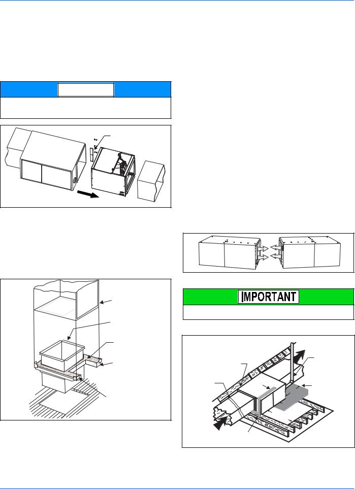
BOTTOM RETURN AND ATTIC INSTALLATIONS
Bottom return applications normally pull return air through a base platform or return air plenum. Be sure the return platform structure or return air plenum is suitable to support the weight of the furnace.
The internal bottom panel must be removed for this application.
Attic installations must meet all minimum clearances to combustibles and have floor support with required service accessibility.
DOWNFLOW APPLICATION
For downflow applications, the furnace must be turned upside-down so that the circulating air enters at the top and exits the furnace at the bottom. The combustion air inducer must be rotated 90° as shown in Figure 22. DO NOT BLOCK COMBUSTION AIR INLET OPENINGS.
HORIZONTAL APPLICATION
FIGURE 9: Horizontal Application
This furnace may be installed in a horizontal position on either side as shown above. It must not be installed on its back.
ATTIC INSTALLATION
Line contact only permissible between lines formed by the intersection of furnace top and two sides and building joists, studs or framing
Filter rack |
|
must be a minimum |
|
distance |
Gas Piping |
of 18” (45.7 cm) |
|
from the |
|
furnace |
|
Supply
Air Vent (Maintain required clearances to combustibles)
|
Sheet metal in |
|
front of furnace |
|
combustion air |
12” |
Openings is |
|
|
|
Recommended |
12”
30” MIN.
Work Area
Return
Air Sediment
Trap
FIGURE 10: Typical Attic Installation
Johnson Controls Unitary Products |
7 |
356485-UIM-G-1211
This appliance is certified for line contact when the furnace is installed in the horizontal left or right position. The line contact is only permissible between lines that are formed by the intersection of the top and two sides of the furnace and the building joists, studs or framing. This line may be in contact with combustible material. Refer to Figure 10.
When a furnace is installed in an attic or other insulated space, keep all insulating materials at least 12 inches (30.5 cm) away from furnace and burner combustion air openings.
During installation, doors should remain on the furnace when moving or lifting.
When moving or handling this furnace prior to installation, always leave the doors on the furnace to provide support and to prevent damage or warping of the cabinet. When lifting the furnace, support the ends of the furnace rather than lifting by the cabinet flanges at the return air openings (bottom or sides) or supply air opening.
It is acceptable to use the primary heat exchanger tubes as a lifting point provided that the tubes are lifted at the front of the heat exchangers where attached to the vestibule panel. Do not use the top return bend of the heat exchangers as lifting points as the tubes may shift out of position or their location brackets/baffles.
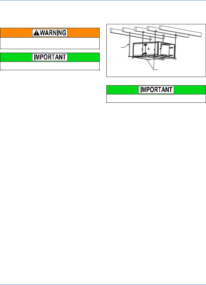
SUSPENDED FURNACE / CRAWL SPACE INSTALLATION
The furnace can be hung from floor joists or installed on suitable blocks or pads. Blocks or pad installations shall provide adequate height to ensure that the unit will not be subject to water damage.
Units may also be suspended from rafters or floor joists using rods, pipe angle supports or straps. In all cases, the furnace should be supported with rods, straps, or angle supports at three locations to properly support the furnace. Place one support at the supply end of the furnace, one support located approximately in the center of the furnace near the blower shelf, and the third support should be at the return end of the furnace. Maintain a 6” (15.2 cm) minimum clearance between the front of the furnace and the support rods or straps.
All six suspension points must be level to ensure proper and quiet furnace operation. When suspending the furnace, use a secure platform constructed of plywood or other building materials secured to the floor or ceiling joists. Refer to Figure 11 for details and additional information.
Support
Rod
Support 

Angle (x3)
Maintain 6” minimum clearance between support rods and front of furnace
FIGURE 11: Typical Suspended Furnace / Crawl Space Installation
During installation, doors should remain on the furnace when moving or lifting.
When moving or handling this furnace prior to installation it is recommended to leave the doors on the furnace to provide support and to prevent damage or warping of the cabinet. When lifting the furnace, support the ends of the furnace rather than lifting by the cabinet flanges at the return air openings (bottom or sides) or supply air opening.
It is acceptable to use the primary heat exchanger tubes as a lifting point provided that the tubes are lifted at the front of the heat exchangers where attached to the vestibule panel. Do not use the top return bend of the heat exchangers as lifting points as the tubes may shift out of position or their location brackets/baffles.
8 |
Johnson Controls Unitary Products |
356485-UIM-G-1211
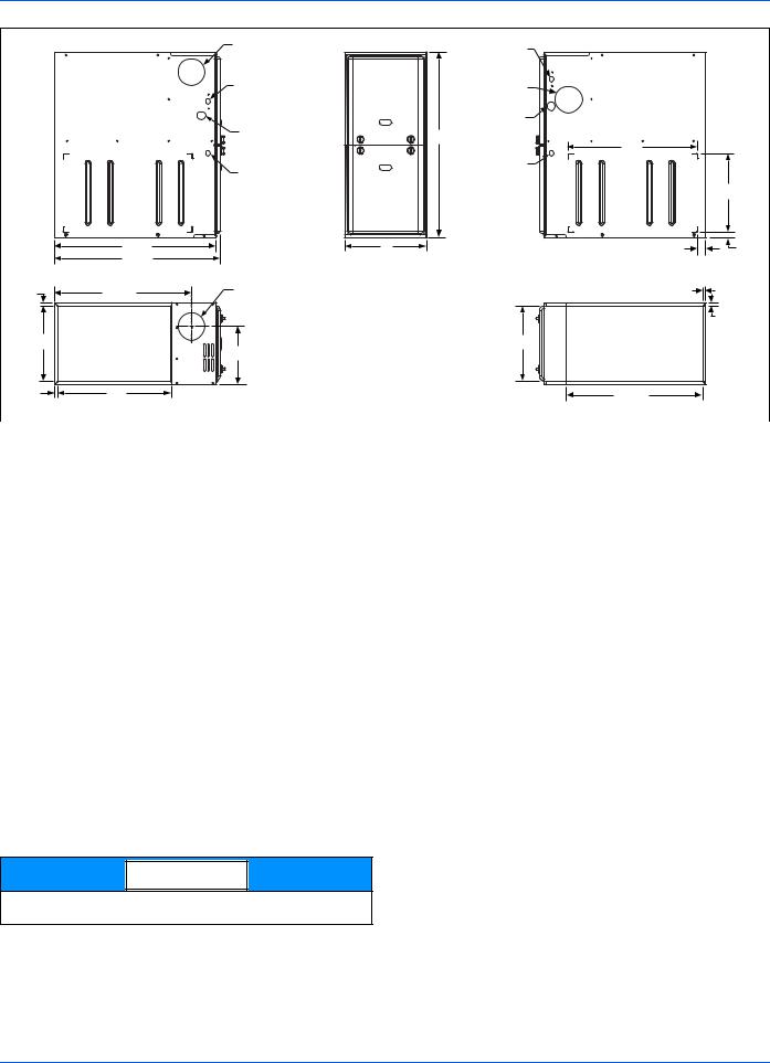
|
LEFT SIDE |
Vent Connection |
|
|
|
||
|
|
Outlet |
|
|
|
Electrical |
|
|
|
Entry |
|
|
|
Gas Pipe |
|
|
|
Entry |
|
|
|
Thermostat |
|
|
|
Wiring |
|
|
28.5” |
|
|
|
29.5” |
|
|
|
|
4” Diameter |
|
.5” |
24.38” |
Vent Connection |
|
Outlet |
|||
|
|
||
|
B |
|
|
|
|
C |
|
.5” |
20” |
|
FRONT |
RIGHT SIDE |
|
|
Electrical |
|
|
Entry |
|
|
Vent |
|
|
Connection |
|
|
Outlet |
|
|
Gas Pipe |
|
|
Entry |
|
|
33” |
|
|
23” |
|
|
Thermostat |
|
|
Wiring |
|
|
|
14” |
A |
1.5” |
1” |
|
.5” |
|
|
|
.5” |
|
B |
|
|
24.25” |
|
|
SUPPLY END |
|
|
|
|
|
|
|
RETURN END |
|||
|
|
|
|
|
|
|
|
|
|
|
|
|
FIGURE 12: Dimensions |
|
|
|
|
|
|
|
|
|
|||
Table 3: Cabinet and Duct Dimensions |
|
|
|
|
|
|
|
|
|
|||
|
|
|
|
|
|
|
|
|
|
|
|
|
BTUH (kW) |
|
Nominal |
|
Cabinet |
|
Cabinet Dimensions (Inches) |
|
|
Approximate |
|||
|
|
|
|
|
Operating Weights |
|||||||
Input |
|
CFM (m3/min) |
|
Size |
|
|
|
|
|
|
|
|
|
|
|
|
|
|
|
|
|
|
|||
|
|
A |
A (cm) |
B |
B (cm) |
|
C |
C (cm) |
Lbs |
|||
|
|
|
|
|
|
|||||||
|
|
|
|
|
|
|
|
|
|
|
|
|
40 (11.7) |
|
800 (22.7) |
|
A |
14 1/2 |
36.8 |
13 3/8 |
34.0 |
|
10.3 |
26.2 |
89 |
60 (17.6) |
|
1000 (28.3) |
|
A |
14 1/2 |
36.8 |
13 3/8 |
34.0 |
|
10.3 |
26.2 |
91 |
60 (17.6) |
|
1200 (34.0) |
|
A |
14 1/2 |
36.8 |
13 3/8 |
34.0 |
|
10.3 |
26.2 |
94 |
80 (23.4) |
|
1200 (34.0) |
|
B |
17 1/2 |
44.4 |
16 3/8 |
41.6 |
|
11.8 |
29.9 |
103 |
80 (23.4) |
|
1600 (45.3) |
|
C |
21 |
53.3 |
19 7/8 |
50.5 |
|
13.6 |
34.5 |
114 |
80 (23.4) |
|
2200 (62.3) |
|
C |
21 |
53.3 |
19 7/8 |
50.5 |
|
13.6 |
34.5 |
119 |
100 (29.3) |
|
1200 (34.0) |
|
B |
17 1/2 |
44.4 |
16 3/8 |
41.6 |
|
11.8 |
29.9 |
108 |
100 (29.3) |
|
1600 (45.3) |
|
C |
21 |
53.3 |
19 7/8 |
50.5 |
|
13.6 |
34.5 |
118 |
100 (29.3) |
|
2000 (56.6) |
|
C |
21 |
53.3 |
19 7/8 |
50.5 |
|
13.6 |
34.5 |
122 |
120 (35.1) |
|
1600 (45.3) |
|
C |
21 |
53.3 |
19 7/8 |
50.5 |
|
15.8 |
40.1 |
123 |
120 (35.1) |
|
2000 (56.6) |
|
C |
21 |
53.3 |
19 7/8 |
50.5 |
|
15.8 |
40.1 |
129 |
130 (38.1) |
|
2000 (56.6) |
|
D |
24 1/2 |
62.2 |
23 3/8 |
59.4 |
|
17.5 |
44.4 |
135 |
SECTION III: FILTERS
FILTER INSTALLATION
All applications require the use of a field installed filter. All filters and mounting provision must be field supplied.
Filters must be installed external to the furnace cabinet. DO NOT attempt to install filters inside the furnace.
NOTICE
Single side return above 1800 CFM is approved as long as the filter velocity does not exceed filter manufacturer’s recommendation.
Table 4: Recommended Filter Sizes (High Velocity 600 FPM)
CFM |
Cabinet |
Side |
Bottom |
(m³/min) |
Size |
(in) |
(in) |
800 (22.7) |
A |
16 x 25 |
14 x 25 |
1000 (28.3) |
A |
16 x 25 |
14 x 25 |
1200 (34.0) |
A |
16 x 25 |
14 x 25 |
1200 (34.0) |
B |
16 x 25 |
16 x 25 |
1600 (45.3) |
B |
16 x 25 |
16 x 25 |
1600 (45.3) |
C |
16 x 25 |
20 x 25 |
2000 (56.6) |
C |
(2) 16 x 25 |
20 x 25 |
2200 (62.3) |
C |
(2) 16 x 25 |
20 x 25 |
2000 (56.6) |
D |
(2) 16 x 25 |
22 x 25 |
1.Air velocity through throwaway type filters may not exceed 300 feet per minute (91.4 m/min). All velocities over this require the use of high velocity filters.
2.Do not exceed 1800 CFM using a single side return and a 16x25 filter. For CFM greater than 1800, you may use two side returns or one side and the bottom or one return with a transition to allow use of a 20x25 filter.
Johnson Controls Unitary Products |
9 |
 Loading...