

Page 1

Page 2

Page 3

Page 4

Support
If at any point you need assistance, we’re here to help.
Visit glas.johnsoncontrol.com/support for how-to videos and frequently asked ques-
tions.
Can’t nd what you’re looking for? Give us a call at 1-833-297-4527(GLAS) and our
technical team can walk you through it.
Before you start, download the GLAS app for easy installation.
Page 5

Included in box
GLAS Thermostat 4 Screws
Wall Plate 4 Drywall Anchors
4 to 5 Wire Adapter Quick Start Guide
Tools required
Screwdriver
Drill
Level
Page 6

Compatibility
GLAS is compatible with most 24 VAC heating and cooling systems.
Use the compatibility checker to ensure your system will work with GLAS by going to
glas.johnsoncontrols.com/compatibilitychecker.
Heating
One or two stages
Cooling
One or two stages
Heat Pump
One or two stages with one-or-two stage auxiliary heat
Fan
Single-speed fan
Auxiliary
Humidier, dehumidier, or ventilator (including HRV or ERV)
Page 7

Terminal descriptions
Note: If you have only one R wire, connect to RC.
Note: If you are replacing an existing thermostat, remove any jumper wires between
R and RH or RC and RH.
Y First stage of cooling or rst stage heat pump
Y2 Second stage of cooling command or second stage heat pump
W First stage of conventional heating or rst stage auxiliary heat for heat pump
systems
W2 Second stage of conventional heating or second stage of auxiliary heat for
heat pump system
Page 8

Terminal descriptions
G Fan
O/B Heat pump reversing valve (supports both O type and B type)
AUX Auxiliary - humidier, dehumidier, or ventilator
R 24 VAC Cool
RH 24 VAC Hot
C 24 VAC Common
Page 9

IMPORTANT: If your thermostat is built into the wall and connected
to thick wires with wire nuts, or if it is labeled 110, 120, or 240 volts,
you have a high voltage system that is not compatible with the GLAS
Thermostat. Do not connect your thermostat to these high voltage
wires. GLAS is only compatible with 24VAC systems.
Page 10

Page 11

WARNING: Risk of Electric Shock.
Disconnect the power supply before making electrical connections.
Contact with components carrying hazardous voltage can cause
electric shock and may result in severe personal injury or death. If you
have any doubts about properly installing the device, please contact
a professional installer.
ADVERTISSEMENT: Risque de décharge électrique.
Débrancher l’alimentation avant de réaliser tout branchement électrique. Tout contact avec des composants conducteurs de tensions
dangereuses risque d’entraîner une décharge électrique et de provoquer des blessures graves, voire mortelles. (need translation)
Page 12
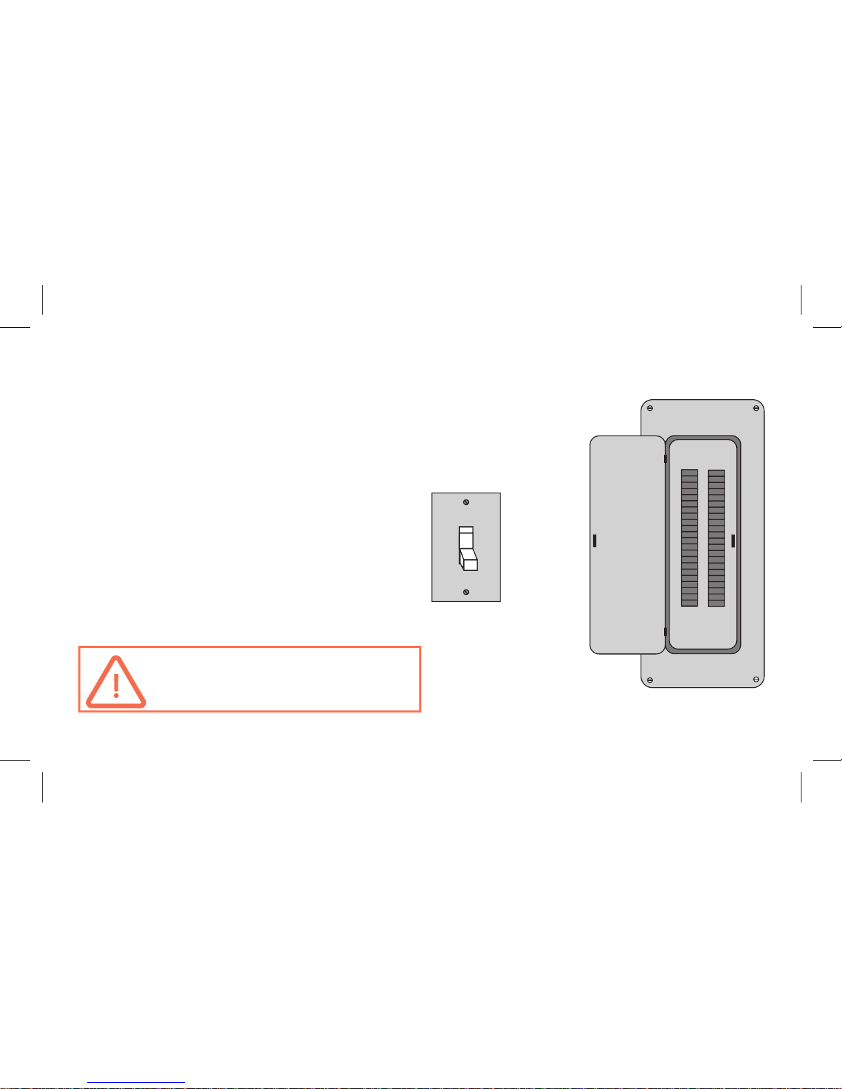
Turn o system power
2. Turn o the power to your heating or
cooling system at your breaker box to
avoid electrocution or shock.
3. If you want to check your system’s power, adjust the temperature on your current
thermostat enough that the system
switches into heating or cooling mode. If
the system does not power on in a few
minutes, it is o.
IMPORTANT: Never work with
live voltage
Page 13

Check old wiring
4. Remove the front plate of your old thermostat and take a picture of the current
wiring that shows the wire colors and con-
nections. This picture will come in handy
when connecting your new thermostat.
Page 14

Connect optional 4 to 5 wire adapter
Note: If you have a C-wire, skip to Step 8.
If you do not have a C-wire to power your
thermostat, use the included adapter to
provide power.
5. Remove the cover of your furnace or air
handling unit to access the control board.
Page 15

Connect the adapter
6. In your HVAC equipment, disconnect
wires from the control board and con-
nect them to the open terminals on the
adapter.
7. Connect the wired terminals on the oth-
er side of the adapter back to the control
board. (Mount with a included magnet)
Page 16

Disconnect your old thermostat
8. Disconnect your old thermostat and
remove the backplate
Note: While disconnecting your old thermostat, use drywall-safe tape to secure the
wires and keep them from falling back into
the wall.
Page 17

Installing your GLAS
9. Remove the frontplate by pulling the
top of the silver cover towards you.
10. Use a level to dry t your GLAS and
mark the wall where you plan to hang
the thermostat. Then drill in the drywall
anchors.
11. Pull all of the wires through the back of
the GLAS thermostat.
Page 18

Attaching your GLAS
12. Loosely attach your GLAS to the wall
using the included screws.
13. Use your level or the level displayed
on the device to straighten the thermostat
and tighten the screws. Do not overtighten.
Page 19

Wiring your GLAS
14. Use the picture you took of your old wiring as a reference and connect the wires
to the corresponding terminals on your new GLAS. See pages 25-26 for wiring examples.
Note: If you have auxiliary devices, such as a humidier, dehumidier, or ventilator,
see pages 27-34 for wiring examples.
Note: You do not need to have a wire for every terminal.
Page 20

Attach the front plate
15. Make sure any access wire is ush
against the wall and press the front plate
until you hear a click.
Page 21

Powering on your HVAC system
16. Return to your system switch or breaker box and turn the power back on.
17. Conrm that the detected wiring
shown on the device screen is correct or
tap any terminals incorrectly identied.
18. Follow the instructions on the device
screen to complete the setup for your
HVAC equipment.
Page 22

Page 23

WIRING
DIAGRAMS
NOTE: Wire colors are for reference only. Not every installation will have wires of the
same color. If you are unsure on the proper installation of the unit, please contact a
licensed electrician or a professional HVAC installer before attempting to install the
unit.
Page 24

Traditional Heat
Page 25

Traditional AC/Heat
Page 26

HVAC/Auxiliary Device
Page 27

Self-Powered Auxiliary Device
Page 28

Furnace-Powered Auxiliary Device
An integrated auxiliary system is built into a furnace or air handler that shares the
same power supply as the rest of the system and only requires a single control wire.
Page 29

Furnace-Powered Auxiliary Device
Page 30

2-Wire Auxiliary Device without C Terminal
An auxiliary device that has two terminals with the same label (HUM, DEHUM, or
AUX) and no C terminal requires a relay pack for operation.
1. Connect the relay pack coil between the auxiliary device and C terminal on your
GLAS device.
2. Connect the switch side of the relay pack to the two terminals on the AUX device.
Page 31

2-Wire Auxiliary Device without C Terminal
Page 32

2-Wire Auxiliary Device with C Terminal
An auxiliary device with one C terminal that does not require a relay pack for operation.
1. Connect the C terminal of the device to the C terminal on the furnace or air handler.
2. Connect the AUX terminal of your GLAS device to the control terminal on the
auxiliary device.
Page 33

2-Wire Auxiliary Device with C Terminal
Page 34

Heat Pump
Page 35

Dual-Stage Heat
Page 36

Dual-Stage Traditional AC
Page 37

Dual-Stage Heat and Traditional AC
Page 38

Dual-Stage Heat/Dual-Stage AC
Page 39

Traditional Heat Pump
Page 40

Dual-Stage Heat Pump
Page 41

Dual-Stage Heat Pump with Traditional Emergency Heat
Page 42

Traditional Heat Pump with Dual-Stage Emergency Heat
Page 43

Traditional Heat Pump with Traditional Emergency Heat
Page 44

Regulatory information to user
FCC Part 15C
1. This device complies with part 15 of the FCC Rules. Operation is subject to the following two conditions: (1) This device may not cause harmful interference, and (2) this device
must accept any interference received, including interference that may cause undesired
operation.
2. This device complies with Industry Canada’s license-exempt RSSs. Operation is subject
to the following two conditions: (1) This device may not cause interference; and
(2) This device must accept any interference, including interference that may cause unde-
sired operation of the device.
Cet appareil est conforme aux ux RSS exemptés de licence d’Industrie Can-ada. L’opération est soumise aux deux conditions suivantes:
(1) Cet appareil ne doit pas provoquer d’interférence; et
(2) Cet appareil doit accepter toute interférence, y compris les interférences pouvant
Page 45

entraîner un fonctionnement indésirable de l’appareil.
CAN ICES-3 (B)/NMB-3(B)
RF Safety Statement
· This device complies with the RF safety requirements for Canada and the USA as per
RSS-102 and FCC Part 1.1310, RF Exposure radiation limits for the General Population /
Uncontrolled Exposure.
· This device shall be installed to maintain a separation distance of 20 cm from the gener-
al population.
Changes or modications not expressly approved by Johnson Controls would void your
authority to operate this device.
Page 46

 Loading...