

Page 1
TABULAR DATA SHEET
B
C
A
Outdoor Split System Air Conditioner 1.5 Thru 5 Tons
MODELS: GCGD18* THRU 60
13 SEER – R-22 – 1 PHASE
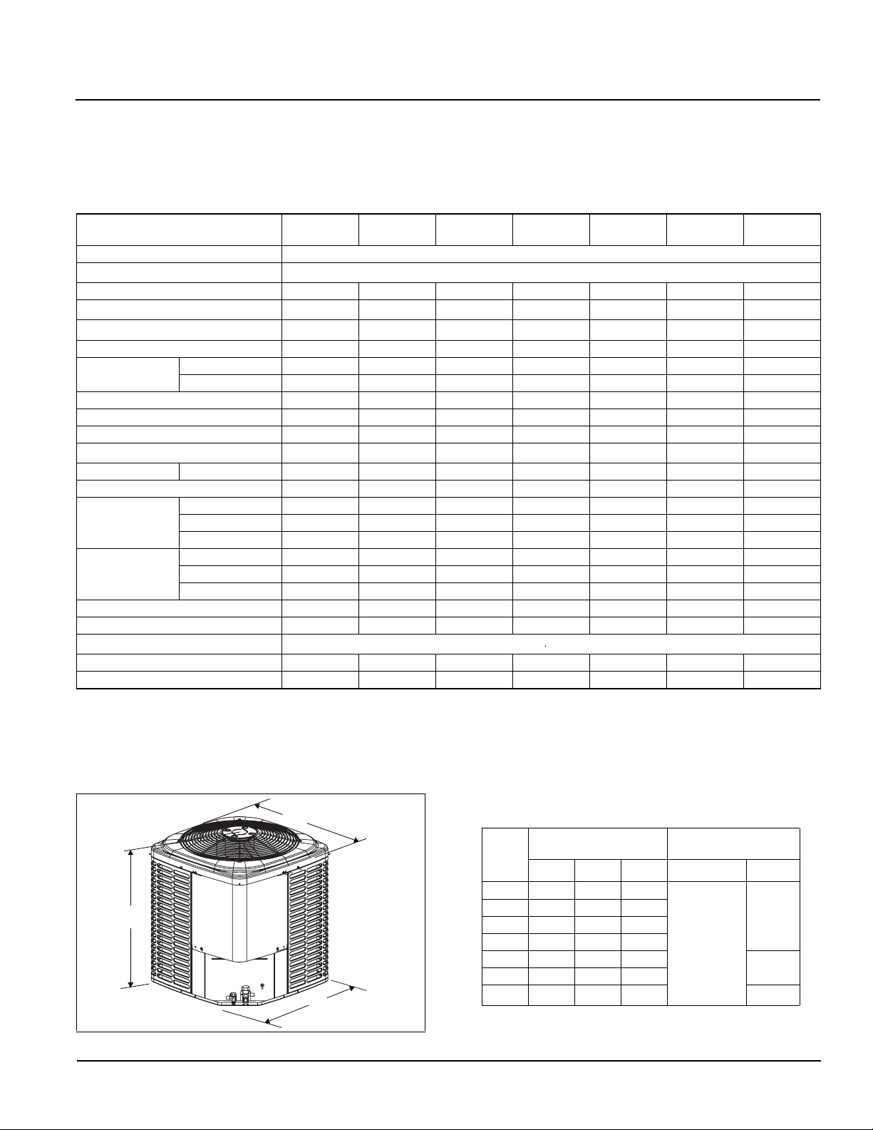
Physical and Electrical Data
MODEL
Unit Supply Voltage 208-230V, 1 60Hz
Normal Voltage Range
Minimum Circuit Ampacity 8.5 13.2 14.0 18.2 19.9 22.7 33.5
Max. Overcurrent Device Amps
Min. Overcurrent Device Amps
Compressor Type Recip Recip Recip Recip Recip Recip Scroll
Compressor Amps
Crankcase Heater No No No No No No No
Factory External Discharge Muffler No No Yes Yes Yes Yes No
Factory External Check Valve No No No No No No No
HS Kit Required with TXV
Fan Motor Amps Rated Load 0.5 0.8 0.80 1.4 1.5 1.5 1.5
Fan Diameter Inches 18 18 18 18 22 22 22
Fan Motor
Coil
Liquid Line Set OD (Field Installed) 3/8 3/8 3/8 3/8 3/8 3/8 3/8
Vapor Line Set OD (Field Installed) 5/8 3/4 3/4 3/4 7/8 7/8 1-1/8
Unit Charge (Lbs. - Oz.)
Charge Per Foot, Oz. 0.66 0.68 0.68 0.68 0.70 0.70 0.76
Operating Weight Lbs. 130 130 150 160 175 176 200
Models with “E” on the end of the model number have an ElectroFin® coating on the outdoor coil.
1. Rated in accordance with AHRI Standard 110-2012, utilization ran ge “A”.
2. Dual element fuses or HACR circuit breaker. Maximum allowable overcurrent protection.
3. Dual element fuses or HACR circuit breaker. Minimum recommended overcurrent protection.
4. See Hard Start Kit Accessory Installation Manual for Hard Start Kit part number for each model.
5. Units have been shipped without refrigerant. Remove nitrogen holding charge, evacuate, and charge to t he system charge listed on the second p age of the dat a
sheet. System charges listed include 15 feet of lineset.
1
2
3
Rated Load 6.4 9.9 10.6 13.4 14.7 17.0 25.6
Locked Rotor365461787886150
4
Rated HP 1/12 1/8 1/8 1/4 1/4 1/4 1/4
Nominal RPM 1100 1075 1075 1100 850 850 850
Nominal CFM 1550 1850 1950 2400 3000 3000 3300
Face Area Sq. Ft. 9.60 9.60 11.30 12.10 16.50 16.50 19.75
Rows Deep 1111111
Fin / Inches 23 23 23 23 23 23 23
5
GCGD18S
21S2X(E)
15 20 20 30 30 35 50
15 15 15 20 25 25 35
Yes Yes Yes Yes Yes Yes No
GCGD24S
21S2X(E)
GCGD30S
21S2(E)
All dimensions are in inches. They are subject to change without notice.
Certified dimensions will be provided upon request.
.
GCGD36S
21S2(E)
187 to 252
See Note 5 Below
Unit
Model
18 28
24 28 23-1/2 23-1/2
30 32 23-1/2 23-1/2
36 34 23-1/2 23-1/2
42 34 29 29
48 34 29 29
60 40 29 29
1. Overall height from bottom of base pan to top of fan guard.
2. Adapter fitting required for 1-1/8” line set.
1
A
GCGD42S
21S2(E)
Dimensions
(Inches)
B C Liquid Vapor
23-1/2 23-1/2
GCGD48S
21S2(E)
Refrigerant Connection
Service Valve Size
3/8”
GCGD60S
21S2(E)
3/4”
7/8”
2
7/8”
Johnson Controls Unitary Products 833101-UTD-B-0612
Page 2
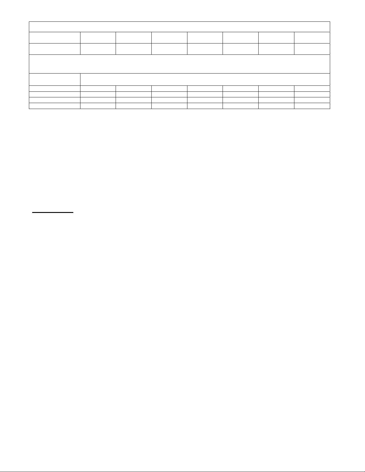
System Charge for Various Matched Systems
3,4
Outdoor Unit
Required Orifice or
1,2
TXV
GCGD18
S21S2X(E)
0.052/2A1 0.059/2A1 0.065/2A1 0.073/2A1 0.081/2C1 0.084/2C1 0.096/2C1
GCGD24
S21S2X(E)
GCGD30
S21S2(E)
GCGD36
S21S2(E)
GCGD42
S21S2X(E)
GCGD48
S21S2(E)
GCGD60
S21S2(E)
Units have been shipped without refrigerant. Remove nitrogen holding charge, select Indoor Unit, select orifice or
TXV, evacuate, and charge to the system charge listed below for matching Indoor Unit. System charges listed
include 15 feet of lineset.
Indoor Unit
FC/MC/PC18 3 - 1 -- -- -- -- -- -FC/MC/PC35 -- -- 3 - 11 -- -- -- -FC/MC/PC43 -- -- -- 4 - 3 4 – 2 -- -FC/MC/62 -- -- -- -- -- -- 5 - 4-
System Charge, lbs - oz
Footnotes:
1. For applications requiring a TXV use S1-1TVM*** series kit.
2. Approved orifice(s) shipped with outdoor unit.
3. Systems matched with furnaces or air handlers not equipped with blower-off delays may require blower Time Delay Kit S1-2FD06700224.
4. PC coils cannot be used in downflow or horizontal applications. FC coils cannot be sued in horizontal applications.
Procedures:
1. Units are shipped from the factory without refrigerant. Remove nitrogen holding charge.
2. Verify the TXV or orifice for the specific matched indoor unit in the system using the above table.
3. System charge weights shown are for the outdoor unit, matched indoor unit, and 15 feet of refrigerant tubing.
4. Add or subtract charge for the amount of interconnecting line tubing less than or greater than 15 feet at the rate specified in Physical and
Electrical Data Table.
5. Weigh in the Total System Charge for the specific matched indoor unit and lineset length.
6. Permanently mark the unit nameplate with the Total System Charge. Total System Charge = Base Charge (as shipped) + charge adder for
matched indoor unit + charge adder for lineset.
Important:
Models 18-48 require Hard Start Kits for TXV matches. Refer to the Hard Start Kit Accessory Installation Manual for the Hard Start Kit part number
for each model.
Thermo Products, LLC
5235 West State Road 10
North Judson, IN 46366
www.thermopride.com
 Loading...