

Page 1
Installation Sheets Manual 121
Gas Combustion Combination Controls and Systems Section G
Technical Bulletin G76x
G76x Direct Spark Ignition Controls
Issue Date 0400
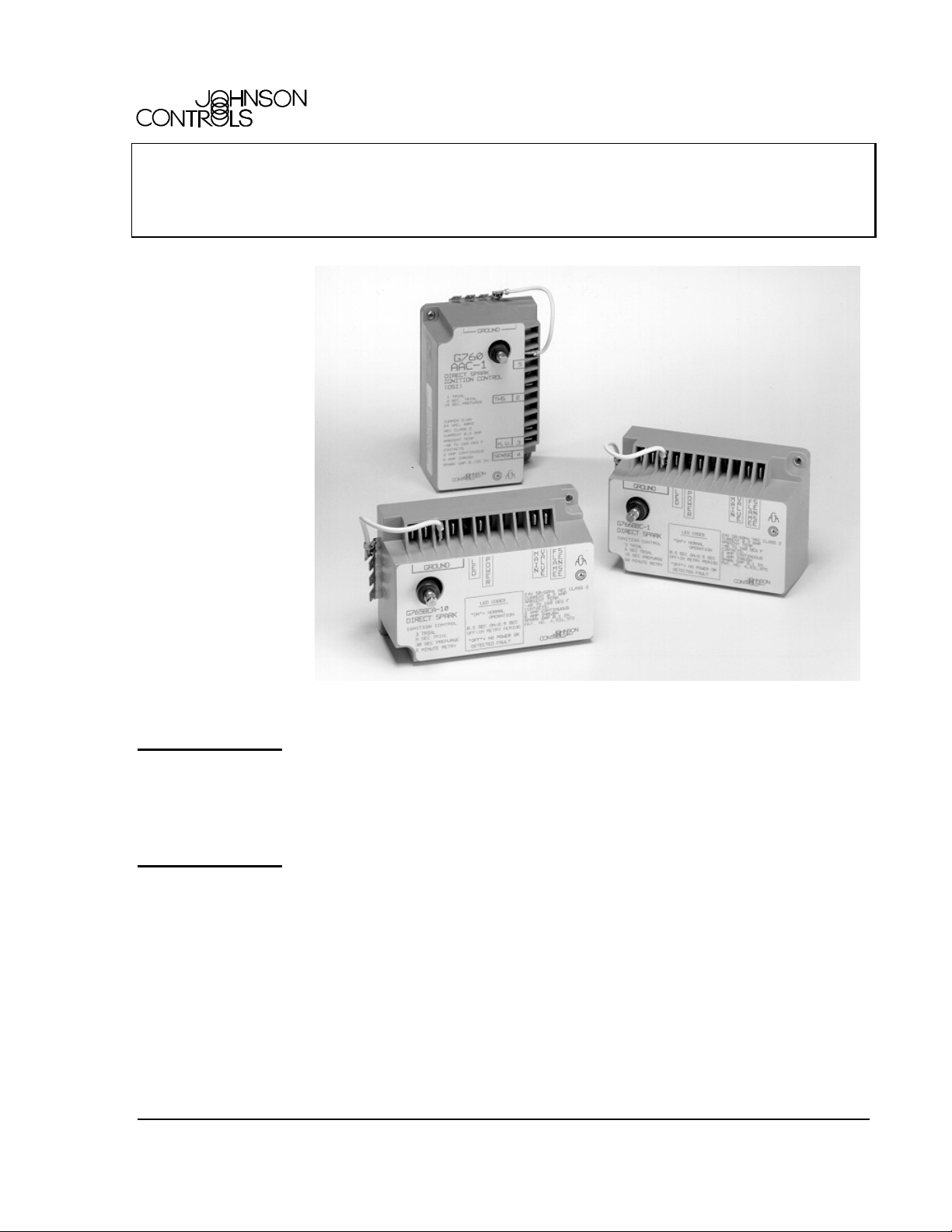
Figure 1: G76x Direct Spark Ignition Controls
Description
The G76x family of controls is designed for direct main burner ignition
and supervision. The G76x is approved for ignition of natural gas,
Liquefied Petroleum (LP) gas, manufactured gas, mixed, or LP gas-air
mixtures.
Application Requirements
Following are the application requirements of the G76x control.
• The G76x can be used on gas-fired equipment with a maximum firing
rate of 117 kW (400,000 Btu/hr). Any application over 117 kW
(400,000 Btu/hr) must have written approval in advance from the
Johnson Controls Heating Products Engineering Department.
• All G76x applications must use a redundant gas valve system where
the main valve seats are in series and open simultaneous for direct
spark burner ignition.
© 2000 Johnson Controls, Inc.
Part No. 24-8143-561, Rev. A www.johnsoncontrols.com
Code No. LIT-121245
1
Page 2

Table 1: Specifications
Ignition Type
Ignition Source
High Voltage Cable
Maximum Length
Flame Sense Cable
Maximum Length
Flame Detection Means
Flame Detection Types
Minimum Flame
Current
Flame Failure
Response Time
Spark Gap
Ignition Trials
Ignition Trial Times
Prepurge Times
Interpurge
Automatic Recycle
Delay Period
Power Requirements
Contact Rating (MV)
Ambient Operating and
Storage Temperature
Humidity
Wiring Connections
Types of Gas
Packaging
Bulk Pack Quantity
Bulk Pack Weight
Agency Listing
Specification
Standards
*Timings listed are for 60 Hz operations. Timings increase 20% for 50 Hz operation.
The performance specifications are nominal and conform to acceptable industry standards. For
application at conditions beyond these specifications, consult the local Johnson Controls office.
Johnson Controls, Inc. shall not be liable for damages resulting from misapplication or misuse of its
products.
Refer to the G76x Series Product Bulletin (LIT-4350420) for necessary information on operating
and performance specifications of this product.
Direct Spark
High voltage spark, capacitive discharge
1,220 mm (48 in.)
1,220 mm (48 in.)
Flame rectification
Remote sensing
0.3 microampere
0.8 second maximum
2.5 mm (0.1 in.) nominal
1 or 3
4, 6, 8, or 10 seconds*
0, 15, or 30 seconds*
30 seconds*
No recycle (G760)
5 minutes* (G765)
60 minutes* (G766)
Control: 24 VAC, 50/60 Hz, nominal
Operation Current: 0.2A nominal + main valve
2A continuous, 5A inrush
-40 to 70°C (-40 to 160°F) standard models
-40 to 80°C (-40 to 175°F) high temperature models
95% RH non-condensing
Spark: Spike, Rajah, or 6.35 mm (1/4 in.) male spade
Control: 6.35 mm (1/4 in.) male spade
4.76 mm (3/16 in.) male spade optional
Natural, Liquefied Petroleum (LP), manufactured, mixed,
or LP gas-air mixture
Bulk pack supplied to original equipment manufacturer
(individual pack optional).
50
15 kg (33 lb)
CSA (AGA/CGA) Certificate Number 164933-1079185
Australian Gas Certificate Number 4524 (G760 models
only)
ANSI Standard Z21.20, Z21.20a, Z21.20b
CAN/CSA-C22.2 No. 199
—G76x Direct Spark Ignition Controls Technical Bulletin
2 G
Page 3

Operating Mode Definitions
The following definitions describe operating conditions.
• Prepurge--Initial time delay between thermostat contact closure and
trial for ignition.
• Trial for Ignition--Period during which the main gas valve and spark
are energized in an attempt to ignite gas at the main burner. The control
attempts to prove flame at the main burner within the trial-for-ignition
time.
• Run--Main gas valve remains energized and spark is turned off after
successful ignition.
• 100% Shutoff--For controls with automatic recycle, main gas did not
ignite within the trial-for-ignition time. The control de-energizes the
spark circuit and main valve.
• Automatic Recycle--If 100% shutoff occurs, the control delays for a
specific recycle delay period before beginning another trial for ignition.
(Models with recycle only.)
• Interpurge--Period between trials for ignition when both the gas valve
and spark are deactivated to allow unburned gas to escape before the
next trial. Interpurge occurs between unsuccessful trials on a multi-trial
control or after a loss of proven flame (flameout).
• Ignition Lockout--Main gas did not ignite within the final
trial-for-ignition time. Open the thermostat contacts for 30 seconds,
then close to restart the sequence of operation. (Models with an
optional Light-Emitting Diode (LED) will flash the LED to indicate
ignition lockout.)
• Flameout--Loss of proven flame.
• Hard Lockout--The control detected a fault. Open the thermostat
contacts for 30 seconds, then close to restart the sequence of operation.
(Models with an optional LED will turn off the LED to indicate a hard
lockout.)
—G76x Direct Spark Ignition Controls Technical Bulletin
G
3
Page 4

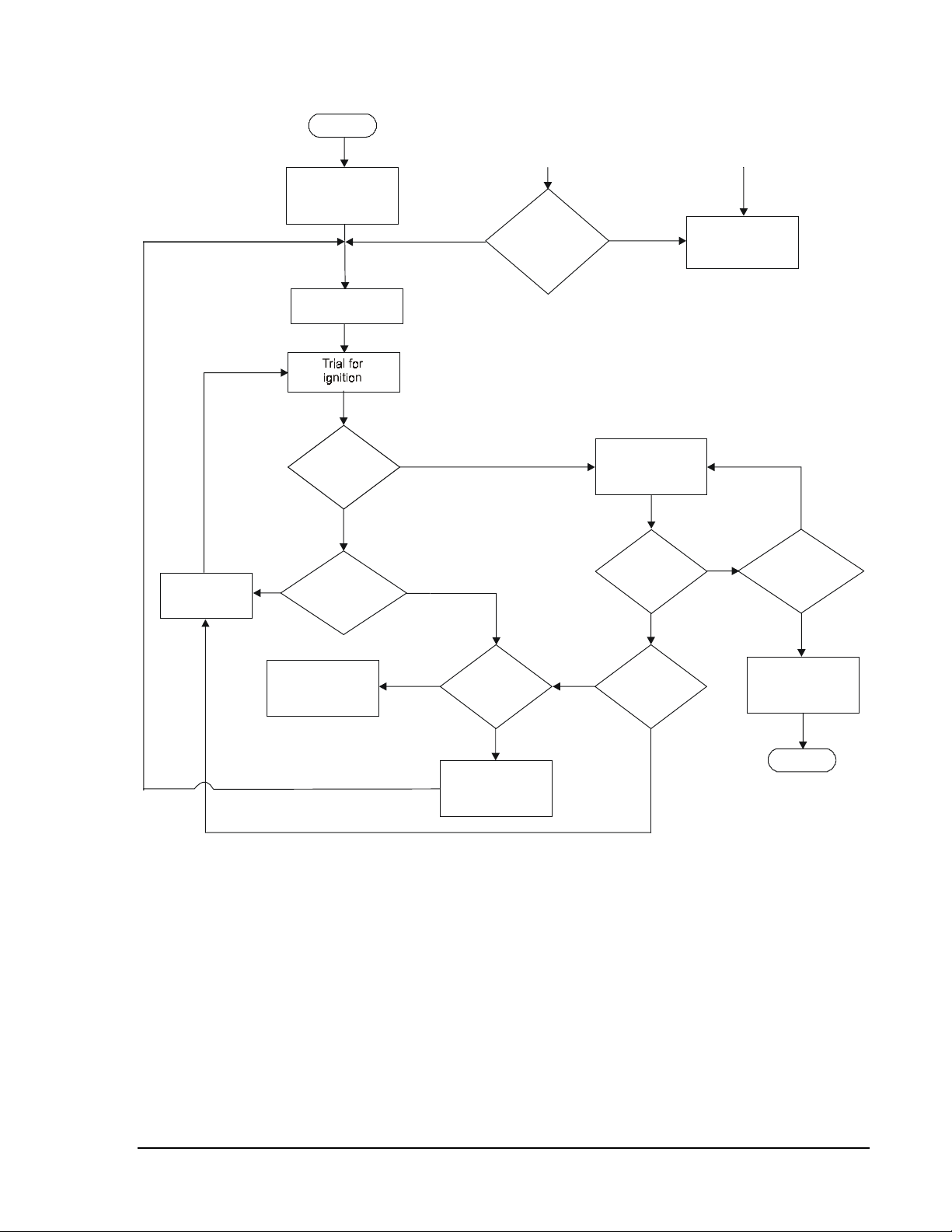
Sequence of Operation
Figure 2 illustrates the sequence of operation of the G76x control.
The G76x is energized on a call for heat from the system thermostat.
(Models with an optional LED will turn on the LED [steady on] until the
call for heat is satisfied.) If the control is equipped with the optional
prepurge, the control will delay for the time selected before initiating a
trial for ignition. During the trial for ignition, the control attempts to light
the main burner by simultaneously energizing the main gas valve and
supplying a continuous spark at the igniter electrode. If the optional
prepurge is not selected, then the trial for ignition begins within 1 second
after the call for heat. The spark is deactivated immediately following the
trial for ignition.
Under normal conditions, the main burner gas ignites within the
trial-for-ignition period. If the control senses main burner flame by the end
of the trial, the control proceeds to a run condition. During the run state,
the control energizes the main valve until the call for heat ends, or until a
flameout occurs. If main burner flame is not sensed by the end of the
trial-for-ignition period, the control may:
• proceed to a 30-second interpurge followed by another trial (three trial
models whose first two trials produced no flame)
• proceed to lockout (no automatic recycle models whose final trial
produced no flame)
• proceed to a recycle delay period followed by another trial (automatic
recycle models whose final trial produced no flame)
If the main burner flame extinguishes during the run state, the control
de-energizes the main gas valve for an interpurge of 30 seconds. After this
period, another trial for ignition is initiated. If this flameout cycle repeats
for a total of 16 times (main burner flame established, then lost), the
control will:
• Enter the lockout mode if the control is a G760. The thermostat
contacts must be opened for 30 seconds and then closed to escape the
lockout condition.
• Enter the 100% shutoff mode and recycle period (5 minute recycle
delay for the G765 and 60 minute recycle delay for the G766) before
beginning another trial for ignition, starting with prepurge.
—G76x Direct Spark Ignition Controls Technical Bulletin
4 G
Page 5
Start
Thermostat
call for heat
Prepurge
Flame pr esent when
not expected
No
Flame
present for
30 seconds?
Ye s
Detected Fault
Hard Lockout
(optional LED
turns off)
Interpurge
Main valve
flame sensed?
No
Maximum
number of trials
attempted?
Ignition Lockout
(optional LED
flashes)
No
Ye s
Ye s
No
Control
with ignition
recycle?
Ye s
Recycle delay
period
Ye s
Run
Flameout?
Sixteenth
flameout?
Figure 2: G76x Sequence of Operation
Ye s
No
No
Ye s
Thermostat
calling for heat?
No
De-energize
control and valves
End
—G76x Direct Spark Ignition Controls Technical Bulletin
G
5
Page 6
Installation and Wiring
IMPORTANT: These instructions are intended as a guide for
qualified personnel installing or servicing
Johnson Controls ignition controls. Carefully follow
all instructions in this bulletin and all instructions on
the appliance. Limit repairs, adjustments, and
servicing to the operations listed in this bulletin or on
the appliance.
!
WARNING: Fire or Explosion Hazard. Avoid serious injury by
carefully following precautions in this bulletin and
all instructions on the appliance. Limit repairs,
adjustments, and servicing to the operations listed in
this bulletin or on the appliance.
!
WARNING: Fire or Explosion Hazard. If the control is installed
in an area that is exposed to water (dripping,
spraying, rain, etc.), it must be protected. If the
control has been exposed to water in any way, do not
use it.
Location and
Mounting
!
WARNING: Shock Hazard. Avoid electrical shock and
equipment damage. Disconnect electrical power and
turn off gas before wiring the control into the circuit.
!
CAUTION: Equipment Damage Hazard. Do not mount the
control where it will be exposed to direct infrared
radiation from the main burner or to temperatures in
excess of the maximum product temperature rating.
Choose a location that provides the shortest, direct cable route to the spark
igniter/flame sensor assembly. Easy access to the terminals is desired for
wiring and servicing. The control may be mounted in any position. Mount
the control on a grounded metal surface with metal screws or bolts through
the mounting holes provided in the enclosure.
—G76x Direct Spark Ignition Controls Technical Bulletin
6 G
Page 7

Electrical
Connections
!
CAUTION: Equipment Damage Hazard. Connect the high
voltage cable to the spark transformer terminal and
spark electrode before applying power to the control.
Ensure that the ground wire is attached to the sensor
assembly and the ignition control ground terminal
strip.
!
CAUTION: Equipment Damage Hazard. Locate all limit and
operating controls in series with the thermostat
terminal (THS 2) on the ignition control.
Check the voltage rating marked on the control and make sure it is suited
to the application. Use a National Electrical Code (NEC) Class 2
transformer to provide 24 VAC under maximum load, including valves.
A transformer having excessive primary impedance due to poor coupling
will affect the ignition potential.
Refer to Figure 3 for wiring diagram. All wiring should be in accordance
with the NEC and all other local codes and regulations. The high voltage
spark transformer cable must not be in continuous contact with a metal
surface. Use standoff insulators. Ensure that the flame sensor wire and
high voltage spark transformer cable are separated from one another by a
minimum of 6.35 mm (1/4 in.) and are not wrapped around any pipe, other
wiring, or accessory.
Spark Electr ode/
Sensor Assembly
Main Burner
Ground
GROUND
5
LED
THS 2
Main
Main
Val ve
M.V. 3
SENSE 4
G76x Ignition Control
Val ve
Limits in
Thermostat
Line Only
Thermostat
Power
Supply
Transformer
Figure 3: Wiring Diagram for G76x Ignition Controls
—G76x Direct Spark Ignition Controls Technical Bulletin
G
7
Page 8

Spark Electrode
and Sensor
Assembly
Instructions for installing the spark electrode and sensor assembly are
typically provided by the appliance manufacturer. It is important to follow
those instructions. If such information is not included, use the following
basic instructions.
Location/Mounting
The spark electrode and sensor assembly must be positioned for easy
access and securely mounted to the main burner to ensure that the
assembly remains properly positioned with respect to the main burner
flame. The main burner flame must engulf at least 9.52 mm (3/8 in.) of the
flame sensor. If a separate flame sensor is used, keep the sensor wire as
short as possible and do not rest it against grounded metal surfaces.
Standoff insulators are recommended.
The spark electrode, flame sensor, and G76x must share a common ground
with the main burner to operate correctly. Thermoplastic insulated wire
with a minimum rating of 105°C (221°F) is recommended for the ground
wire. Ensure that the flame sensor wire and the high voltage spark
transformer wire are separated from one another by a minimum distance of
6.35 mm (1/4 in.) and are not wrapped around any pipe, other wiring, or
accessory.
—G76x Direct Spark Ignition Controls Technical Bulletin
8 G
Page 9

Checkout and Startup Procedure
!
WARNING: Fire or Explosion Hazard. Avoid personal injury
or property damage by making sure the control
functions properly and there are no gas leaks.
Follow this checkout and startup procedure before
leaving the installation.
!
WARNING: Fire or Explosion Hazard. Do not attempt to
check out this system by manually lighting the
main burner.
Make sure all components function properly by performing the following
shutoff test.
1. With the gas and thermostat off, turn on power to the appliance.
2. Turn the thermostat to the highest setting and verify that the control
goes through the operating sequence to a shutoff condition.
Note: The burner will not light because the gas is off.
3. Turn off the thermostat.
4. Turn on the gas and purge gas lines of all air.
5. Check for gas leaks on all pipe joints upstream of the gas valve with a
soap solution.
6. Turn the thermostat to the highest setting and verify successful
ignition and a normal run condition for at least three minutes. If the
appliance fails to run, see the Service Checkout Procedures section.
7. Check for gas leaks on all pipe joints downstream of the gas valve
with a soap solution.
8. Turn the thermostat down for at least 30 seconds, and then back up
again. Verify successful ignition at least three times.
9. Return the thermostat to a normal temperature setting before leaving
the installation.
—G76x Direct Spark Ignition Controls Technical Bulletin
G
9
Page 10

Thermostat Heat Anticipator Settings
The anticipator setting is normally equal to the ignition system current
draw, plus that of the main valve.
Due to variations in appliance wiring and valves, it is advisable to measure
the actual current draw of the heating system at the thermostat location.
Measuring the current draw can be accomplished by opening the
thermostat contacts (lowering the setpoint), and installing an AC ammeter
across the terminals, or by using a clamp-on ammeter with a 10-turn
multiplier attached to the terminals. See Figure 4.
IMPORTANT: Measuring the current with an ammeter will energize
the system. Wait until the appliance is in the run
condition before taking a current draw measurement.
To
Heating
System
WR
AC Ammeter Low Scale Setting
To
Heating
System
WR
Ten Turns
Clamp-on Ammeter
(divide reading by ten.)
Figure 4: Measuring the Thermostat Current
—G76x Direct Spark Ignition Controls Technical Bulletin
10 G
Page 11

Replacement Procedure
!
WARNING: Shock Hazard. Avoid electrical shock and
equipment damage. Disconnect electrical power and
turn off gas before wiring the control into the circuit.
!
CAUTION: Equipment Damage Hazard. Label all wires prior
to disconnection when servicing controls. Wiring
errors can cause improper and dangerous operation.
Verify proper operation after servicing.
Perform the following procedure to replace the existing direct spark
ignition control.
1. Shut off power to the appliance.
2. Turn off the gas at the manual shutoff valve adjacent to the appliance.
3. Label each wire with the correct terminal designation prior to
disconnection.
4. Disconnect the power supply (transformer) and the thermostat lead
wire at the ignition control.
5. Disconnect the sensing probe lead from Terminal 4 on the ignition
control.
6. Disconnect the high voltage cable from the spark transformer.
7. Disconnect the Main Valve 3 lead from the ignition control.
8. Disconnect any wires connected to the ground terminals.
9. Remove the screws holding the ignition control assembly in place.
10. Remove the ignition control and discard.
11. Using the same holes as the old ignition, mount the new G76x control
with metal screws or bolts through the mounting holes in the
enclosure.
12. Refer to the Installation and Wiring section for electrical connections
and wiring information. The replacement G76x control has a Spike
transformer connection. Refer to the Modifying Existing Ignition Cable
section for connection to a Spike transformer.
13. Perform the Checkout and Startup Procedure before leaving the
installation.
—G76x Direct Spark Ignition Controls Technical Bulletin
G
11
Page 12

Modifying
Existing Ignition
Cable
All spark ignition controls have a spark transformer connected to a high
voltage cable. There are three types of connection for the high voltage
cable: Spike, Rajah, and 6.35 mm (1/4 in.) male spade (see Figure 5).
The replacement G76x has a Spike transformer. When replacing a control
that has a Rajah or male spade connection, the crimp-on connector must be
cut off.
1. Slide the rubber boot up the cable.
2. Cut the lead just above the connector (see Figure 6). Make a straight
cut perpendicular to the cable.
3. Center the exposed wire on the end of the lead over the spike in the
spark transformer and push the wire lead down firmly over the spike
(see Figure 7).
4. Ensure the lead is inserted all the way into the spark transformer.
Slide the boot back down the cable and over the spark transformer.
Spike Connection
Rajah Connection
6.35 mm (1/4 in.)
Male Spade
Figure 5: High Voltage Cable Connectors
Insulating Boot
High Voltage Cable
Cut off connector here.
Crimp-on
Connector
Figure 6: High Voltage Cable with Crimp-On Connector
High Voltage Cable
Spike must be in
contact with the
center wires.
Figure 7: Spark Transformer Connection
—G76x Direct Spark Ignition Controls Technical Bulletin
12 G
Page 13

Service Checkout Procedures
!
WARNING: Fire or Explosion Hazard. Do not attempt
servicing or troubleshooting when the LED is
flashing (recycle mode). The control automatically
energizes the system and could cause personal
injury or property damage.
If the system does not function properly, determine the cause using the
procedures in this section.
Preliminary
Checks
Failure
Conditions and
Corrective
Action
Before proceeding with troubleshooting the system, check the following:
• Are all mechanical and electrical connections tight?
• Is the system wired correctly?
• Is the gas inlet pressure per the manufacturer’s specifications?
• Is the system powered?
• Is the thermostat calling for heat?
• Is the optional LED flashing? If so, the control is in recycle mode or it
has entered an ignition lockout.
• Is the optional LED off? If so, the control is not receiving power, or it
has detected a fault. Faults are:
- flame present for more than 30 seconds at call for heat
- a defective control
There are three potential system failure conditions:
• No spark is present, and system does not work.
• Spark is present, but main burner does not light.
• Main burner lights, but does not stay lit.
Determine the failure condition, then use the respective flowchart on the
following pages to troubleshoot the system. Perform the procedures in the
Checkout and Startup Procedure section after any servicing.
—G76x Direct Spark Ignition Controls Technical Bulletin
G
13
Page 14

Start
Is 24 VAC
available at
transformer?
Ye s
Is 24 VAC
present from
Terminal THS 2
to ground?
Ye s
Is jumper
installed from
Terminal 5 to
ground?
Ye s
Determine why
voltage is not
present
Correct
No
No
No
Is power
available
to primary?
Ye s
Replace the
transformer
Turn off supply voltage.
Is high voltage cable
securely attached to
spark transformer?
No
Close
contacts
No
Are thermostat
contacts and limit
control contacts
closed?
Ye s
Check continuity of
wiring to determine
why voltage does
not exist at THS 2
No
jumper
Control in
recycle mode
Open thermostat
contacts for 30 seconds.
Close contacts and wait
for prepurge (if applicable)
period. Is spark
present now?
No
Install
Ye s
Is control a
G765 or G766?
Ye s
Is LED
Flashing?
No
No
Replace
Replace
G76x control
Ye s
Is condition
No
No
of high voltage
cable good (not
brittle, burnt,
or cracked?)
Ye s
Is spark electrode
ceramic cracked or
is electrode
grounded out?
Ye s
System was in lockout.
Observe a complete
operat ing cycle to
determine why control
Replace electrode assembly
End
Figure 8: No Spark, and System Does Not Work
Ye s
locked out.
—G76x Direct Spark Ignition Controls Technical Bulletin
14 G
Page 15

Start
Is
main valve wiring
correct and
secure?
Ye s
No
Correct
Is 24 VAC
present between
Terminal 3 and
ground?
Ye s
Does
continuity exist in
wiring to main
valve?
Ye s
Is inlet
gas pressure per
manufacturer’s
specifications?
Ye s
Is spark gap
per manufacturer’s
specifications and
in gas stream?
No
No
No
No
Replace
control
Replace
wiring
Correct
Correct or
replace electrode
assembly
Ye s
Replace
gas valve
End
Figure 9: Spark Present, but Main Burner Does Not Light
—G76x Direct Spark Ignition Controls Technical Bulletin
G
15
Page 16

Start
Is
flame sensor
wiring correct and
secure?
Ye s
No
Correct
Does continuity
exist in wiring
to flame sensor?
Ye s
Is flame sensor
ceramic cracked or
broken?
No
Is flame
sensor
clean?
Ye s
Does continuity
exist between burner
and control
ground?
Ye s
No
No
No
Ye s
Replace
wiring
Replace
sensor
Clean sensor
with steel wool
or replace
Add or
replace
wiring
Figure 10: Main Burner Lights, but Does Not Stay Lit
—G76x Direct Spark Ignition Controls Technical Bulletin
16 G
Is flame sensor
positioned per the
manufacturer’s
specifications?
Ye s
Is flame
sense current
> 0.3 microamperes
DC?
No
Correct
No
Ye s
Correct
Replace
control
End
Page 17

Repairs and Replacement
!
CAUTION: Label all wires prior to disconnection when servicing
controls. Wiring errors can cause improper and
dangerous operation. Verify proper operation after
servicing.
The G76x controls are not field repairable. Do not attempt field repairs.
Use only an exact or factory-recommended replacement control.
All other accessories, such as flame sensors, electrode assemblies, pilot
assemblies, and leads can be obtained through the original equipment
manufacturer or a Johnson Controls distributor.
—G76x Direct Spark Ignition Controls Technical Bulletin
G
17
Page 18

Notes
—G76x Direct Spark Ignition Controls Technical Bulletin
18 G
Page 19

Notes
—G76x Direct Spark Ignition Controls Technical Bulletin
G
19
Page 20

Notes
Controls Group www.johnsoncontrols.com
507 E. Michigan Street
P.O. Box 423 Installation Sheets Manual
Milwaukee, WI 53201 Printed in U.S.A.
—G76x Direct Spark Ignition Controls Technical Bulletin
20 G
FAN 121
 Loading...