

Page 1
Installation Sheets Manual 121
Gas Combustion Combination Controls and Systems Section G
Technical Bulletin G670
Issue Date 0300
G670 Intermittent Pilot Ignition Controls
Description
Application Requirements
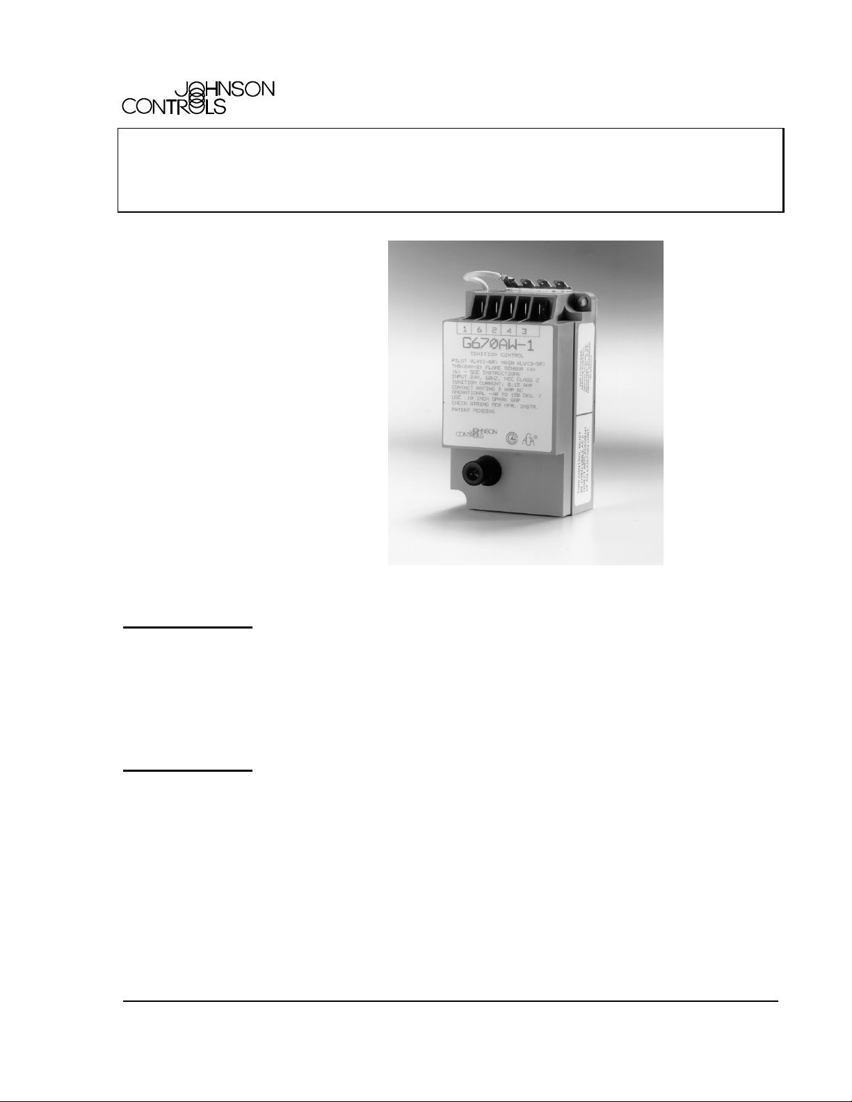
Figure 1: G670 Intermittent Pilot Ignition Control
The G670 is a Non-100% Lockout Intermittent Pilot Ignition (IPI) control
that replaces the G67AG and G67BG ignition controls. The G670 is used to
automatically light a pilot burner and energize the main burner gas valve in
response to a call for heat from the system thermostat. When the call for heat
is satisfied, the thermostat opens and the G670 de-energizes the pilot and
main burner gas valves.
Following are the application requirements of the G670 control.
• The G670 can be used with equipment with a maximum firing rate of
117 kW (400,000 Btu/hr). Any application greater than 117 kW
(400,000 Btu/hr) must have written approval in advance from the
Heating Products Engineering Department.
• All G670 applications must use a redundant gas valve system with the
main valve seats in series.
© 2000 Johnson Controls, Inc.
Part No. 24-8143-162, Rev. B www.johnsoncontrols.com
Code No. LIT-121240
1
Page 2
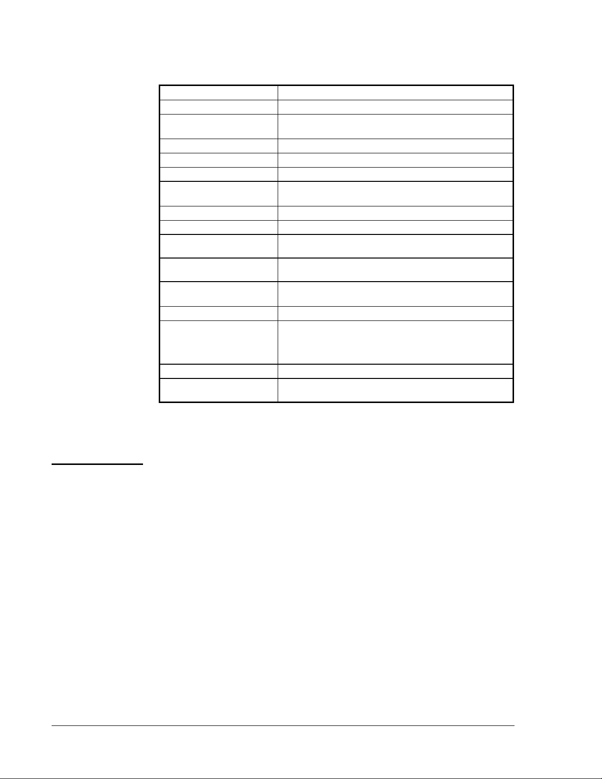
Table 1: Specifications
Ignition Type
Ignition Source
High Voltage Cable
Length
Flame Detection Means
Flame Detection Types
Minimum Flame Current
Flame Failure Response
Time
Spark Gap
Ignition Trial Time
Power Requirements
Contact Rating
Ambient Operating and
Storage Temperature
Humidity
Types of Gas
Agency Listing
Specification Standards
The performance specifications are nominal and conform to acceptable industry
standards. For application at conditions beyond these specifications, consult the
local Johnson Controls office. Johnson Controls, Inc. shall not be liable for
damages resulting from misapplication or misuse of its products.
Indirect
High voltage spark, capacitive discharge
915 mm (36 in.) maximum
Flame rectification
Remote sensing
0.2 microampere
0.8 second, maximum
2.5 mm (0.1 in.) nominal
Infinite
Control: 24 VAC, 50/60 Hz, nominal
Operation Current: 0.15A nominal + valves
Main Valve: 2A continuous, 5A inrush
Pilot Valve: 2A continuous, 5A inrush
-40 to 66°C (-40 to 150°F)
95% RH non-condensing
Natural
(Liquefied Petroleum [LP], manufactured, mixed, or
LP gas-air mixture may be used in a well vented or
outdoor application.)
CSA (AGA/CGA) Certificate Number 112520-0-19
ANSI Standard Z21.20
CSA C22.2-No. 199
Operating Mode Definitions
2 G
G670 Intermittent Pilot Ignition Controls Technical Bulletin
The following definitions describe operating conditions.
• Trial for Ignition--Period during which the pilot valve and spark are
activated attempting to ignite gas at the main burner. The
trial-for-ignition period is infinite for the G670s and ends once the
pilot flame is detected or the call for heat ends.
• Run--The main valve remains energized and the spark is turned off
after successful ignition.
• Flameout--Loss of proven flame. Should a flameout occur, the main
valve closes and the spark recurs within 0.8 second.
Page 3
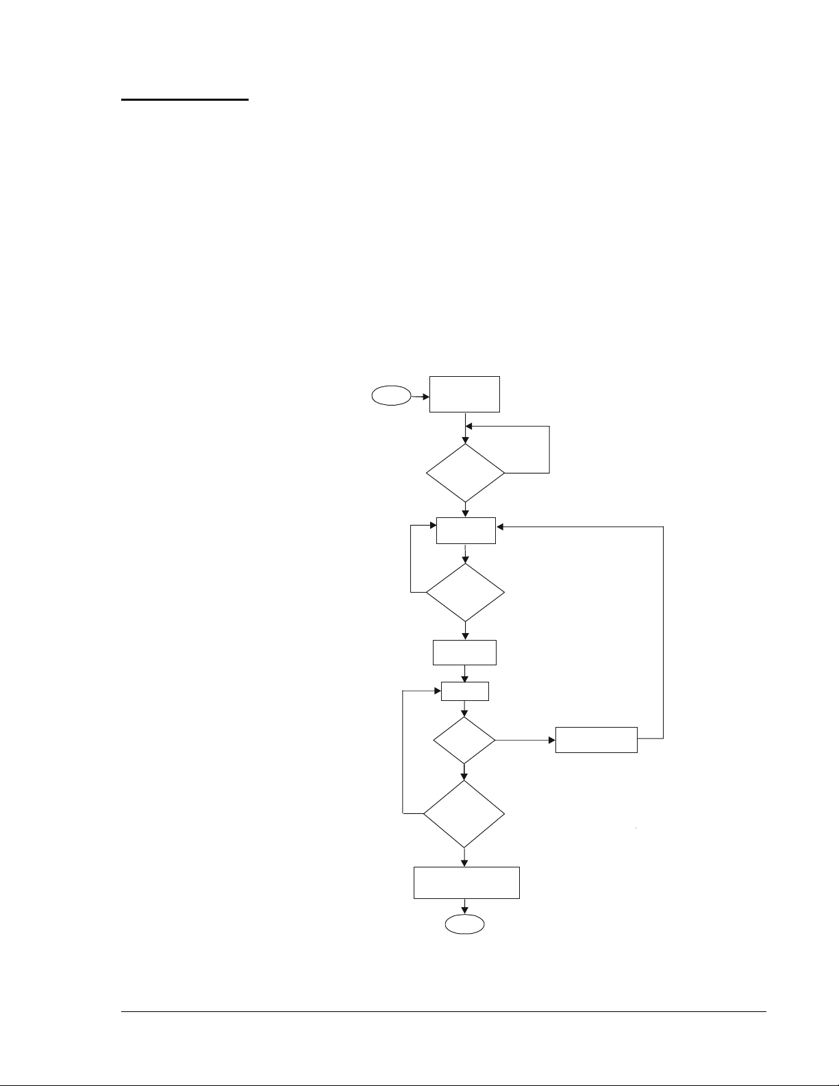
Sequence of Operation
Figure 2 illustrates the sequence of operation for the G670 ignition control.
On a call for heat from the system thermostat, the G670 simultaneously
opens the pilot valve and supplies a continuous spark to the pilot burner’s
electrode. When the pilot burner gas ignites, the pilot flame sensor detects
the pilot flame and signals the G670 to energize the main gas valve and
discontinue the spark. The main gas valve will not be energized until the
flame sensor detects the presence of the pilot flame.
If the pilot flame goes out (with the thermostat still calling for heat), the
G670 will de-energize the main gas valve and provide a continuous spark
at the pilot burner’s electrode. When the pilot flame is re-ignited and
detected by the pilot flame sensor, the main gas valve is energized and the
spark is shut off. The G670 de-energizes the pilot gas valve and main
burner gas valve when the thermostat stops calling for heat.
Start
No
Ye s
Thermostat
Call for Heat
Flame
Present?
No
Trial for
Ignition
Pilot
Flame
Sensed?
Ye s
Energize
Main Valve
Run
Flameout?
No
Thermostat
Calling for
Heat?
No
Ye s
Ye s
De-energize
Main Valve
De-energize Control
Pilot and Main Valves
End
Figure 2: Sequence of Operation
G670 Intermittent Pilot Ignition Controls Technical Bulletin
G
3
Page 4
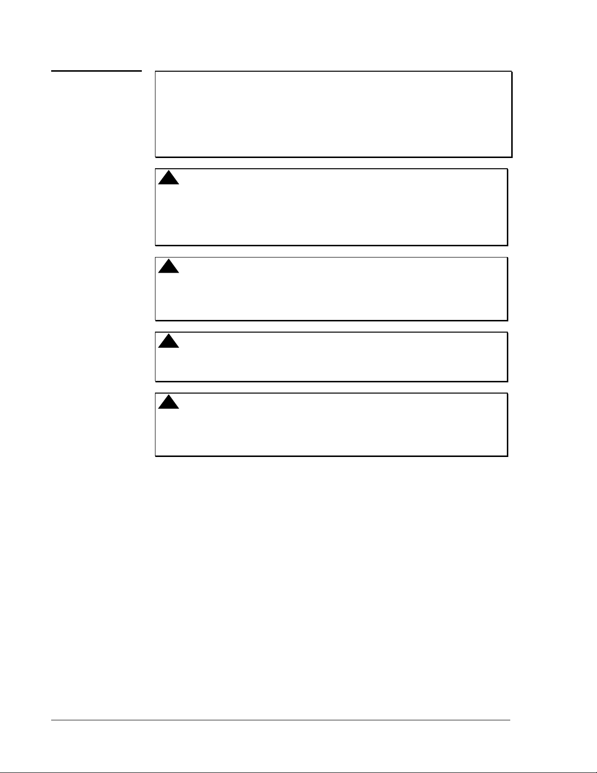
Installation
IMPORTANT: These instructions are intended as a guide for qualified
personnel installing or servicing Johnson Controls
ignition controls. Carefully follow all instructions in
this bulletin and all instructions on the appliance. Limit
repairs, adjustments, and servicing to the operations
listed in this bulletin or on the appliance.
!
WARNING: Fire or Explosion Hazard. Avoid serious injury by
carefully following precautions in this bulletin and all
instructions on the appliance. Limit repairs,
adjustments, and servicing to the operations listed in
this bulletin or on the appliance.
!
WARNING: Fire or Explosion Hazard. If the control is installed
in an area that is exposed to water (dripping, spraying,
rain, etc.), it must be protected. If the control has been
exposed to water in any way, do not use it.
!
WARNING: Shock Hazard. Avoid electrical shock and equipment
damage. Disconnect electrical power and turn off the
gas before wiring the control.
Mounting
!
CAUTION: Equipment Damage Hazard. Label all wires prior to
disconnection when servicing controls. Wiring errors
can cause improper and dangerous operation. Verify
proper operation after servicing.
Perform the following procedure to install the G670 ignition control.
1. Shut off power to the appliance.
2. Turn off gas at the manual shutoff valve adjacent to the appliance.
3. Label each wire with the correct terminal designation prior to
disconnection.
4. Disconnect the power supply (transformer) and the thermostat lead
wire at the ignition control.
5. Disconnect the sensing probe lead from Terminal 4 on the ignition
control.
6. Disconnect the high voltage cable from the spark transformer.
7. Disconnect the Pilot Valve 1 and Main Valve 3 leads from the ignition
control.
8. Disconnect any wires connected to the ground terminals on the ignition
control.
4 G
G670 Intermittent Pilot Ignition Controls Technical Bulletin
Page 5
9. Remove the screws holding the ignition control assembly in place.
10. Remove the ignition control and discard.
11. Using the same holes as the old ignition, mount the new G670 control
on a grounded metal surface with metal screws or bolts through the
mounting holes provided on the enclosure.
Modifying
Existing Ignition
Cable
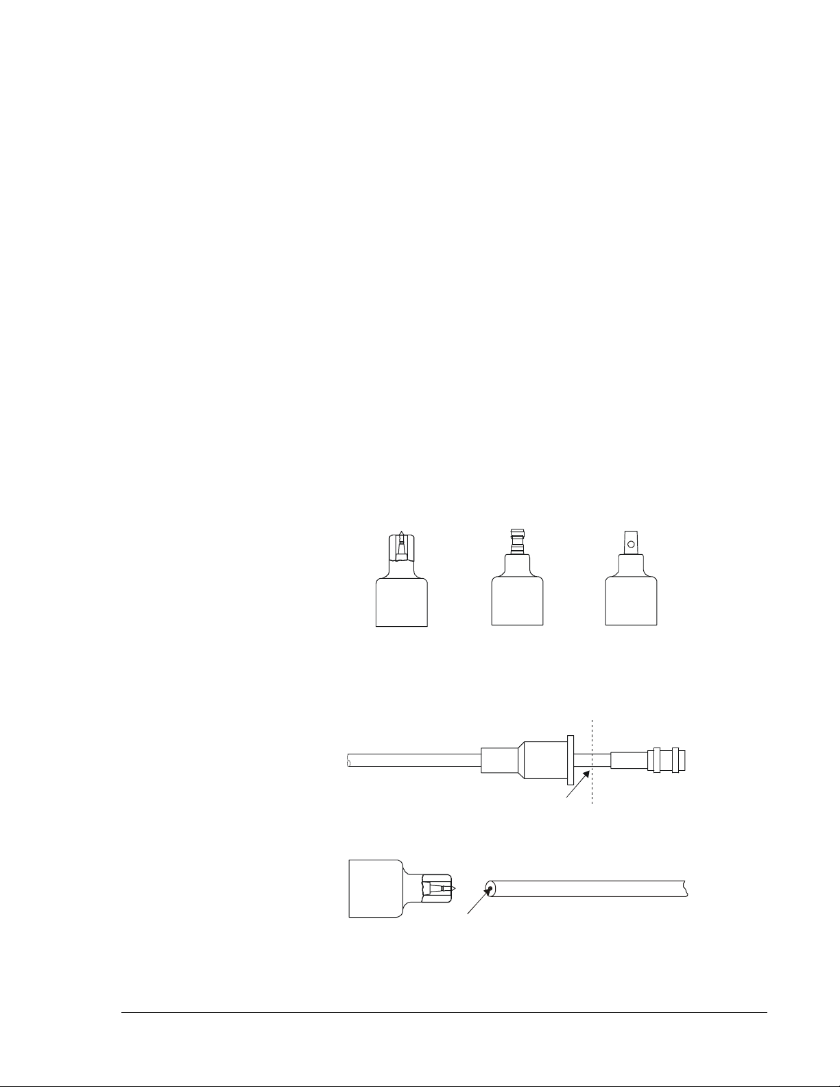
All spark ignition controls have a spark transformer connected to a high
voltage cable. There are three types of connection for the high voltage
cable: Spike, Rajah, and 6.35 mm (1/4 in.) male spade (see Figure 3). The
G670 has a Spike transformer. When replacing a control that has a Rajah
or male spade connection, the crimp-on connector must be cut off.
1. Slide the rubber boot up the cable.
2. Cut the lead just above the connector (see Figure 4). Make a straight
cut perpendicular to the cable.
3. Center the exposed wire on the end of the lead over the spike in the
spark transformer and push the wire lead down firmly over the spike
(see Figure 5).
4. Ensure the lead is inserted all the way into the spark transformer. Slide
the boot back down the cable and over the spark transformer.
Spike Connection
Rajah Connection
6.35 mm (1/4 in.)
Male Spade
Figure 3: High Voltage Cable Connectors
Insulating Boot
High Voltage Cable
Cut off connector here.
Crimp-on
Connector
Figure 4: High Voltage Cable with Crimp-On Connector
High Voltage Cable
Spike must be in contact
with the center wires.
Figure 5: Spark Transformer Connection
G670 Intermittent Pilot Ignition Controls Technical Bulletin
G
5
Page 6
Wiring
!
CAUTION: Equipment Damage Hazard. Connect the high
voltage cable to the spark transformer terminal and
spark electrode (pilot burner assembly) before
applying power to the control. Ensure the ground wire
is attached to the pilot burner and control ground
terminal strip.
!
CAUTION: Equipment Damage Hazard. Locate all limit and
operating controls in series with the thermostat
terminal (THS 2) on the ignition control.
Check the voltage rating marked on the control and make sure it is suited to
the application. Use a National Electrical Code (NEC) Class 2 transformer
to provide 24 VAC under maximum load, including valves. A transformer
having excessive primary impedance due to poor coupling will affect the
ignition potential.
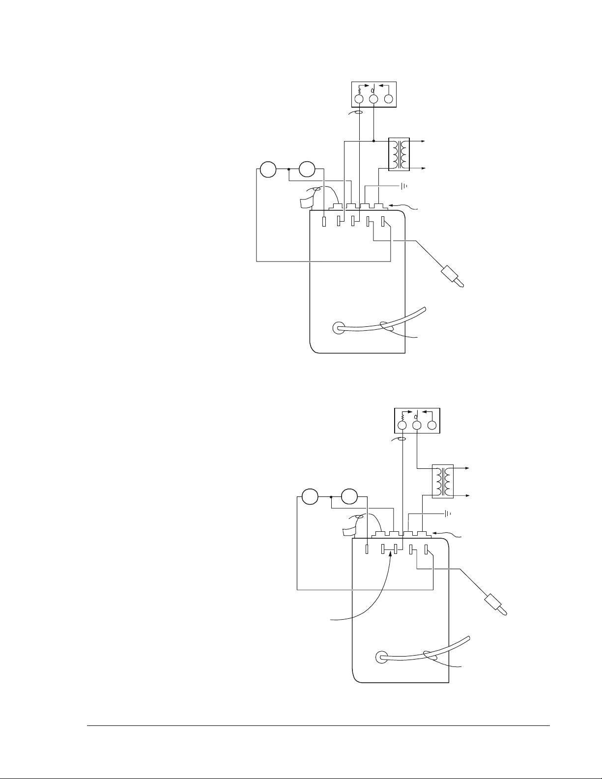
Refer to Figures 6 through 9 for wiring diagrams. All wiring should be in
accordance with the NEC and all other local codes and regulations. The
high voltage spark transformer cable must not be in continuous contact
with a metal surface. Use standoff insulators. Ensure that the flame sensor
wire and the high voltage spark transformer cable are separated from
one another by a minimum distance of 6.35 mm (1/4 in.) and are not
wrapped around any pipe, other wiring, or accessories.
6 G
G670 Intermittent Pilot Ignition Controls Technical Bulletin
Page 7
Limits in
the Thermostat
Line Only
Thermostat
RW Y
MV
Jumper
PV
24
VAC
0.21 in
5
62
1
43
Power
Supply
Pilot
Burner
Ground
Ground Terminals
Flame
Sensor
High Voltage
Cable
Figure 6: Replacement Wiring Diagram
if the Original Control is a G67AG
Thermostat
RW Y
MV
Install the jumper supplied
with the replacement control
between Terminals 2 and 6.
Figure 7: Replacement Wiring Diagram
if the Original Control is a G67BG
the Thermostat
PV
Jumper
5
Limits in
Line Only
1
6
2
24
VA C
43
Power
Supply
Pilot
Burner
Ground
Ground
Terminals
Flame
Sensor
High Voltage
Cable
G670 Intermittent Pilot Ignition Controls Technical Bulletin
G
7
Page 8
Thermostat
RW Y
High Limits
In This Line Only
MV
MV
Power
Supply
Pilot
Burner
Ground
Install the jumper supplied
with the replacement control
between Terminals 2 and 6.
24
VAC
Jumper
PV
5
62
1
Brown
White
43
Black
High Voltage
Cable
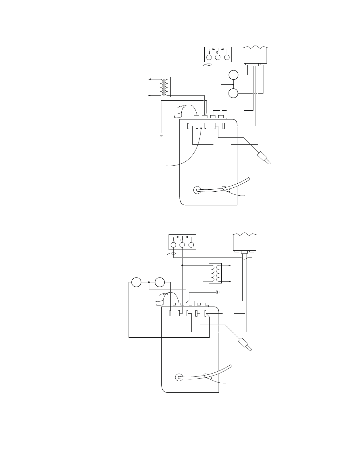
Figure 8: Wiring Diagram for G670 with Y79B _ _
Y79
PV
Flame
Sensor
High Limits
In This Line
MV
Only
PV
Jumper
5
Thermostat
RW Y
62
1
24
VAC
43
Black
White
Y79
THS
Power
Supply
Pilot
Burner
Ground
Red
Flame
Sensor
High Voltage
Cable
8 G
Figure 9: Wiring Diagram for G670 with a Y79A _ _
G670 Intermittent Pilot Ignition Controls Technical Bulletin
Page 9

Checkout and Startup Procedure
!
WARNING: Fire or Explosion Hazard. Avoid personal injury or
property damage by making sure the control functions
properly and there are no gas leaks. Follow this
checkout and startup procedure before leaving the
installation.
!
WARNING: Fire or Explosion Hazard. Do not attempt to check
out this system by manually lighting the pilot. This
could energize the main valve.
Make sure all components are functioning properly by performing the
following shutoff test.
1. With the gas and thermostat off, turn on power to the appliance.
2. Turn on the thermostat to the highest setting and verify that the control
goes through the operating sequence to a shutoff condition.
Note: The burner will not light because the gas is off.
3. Turn off the thermostat.
4. Turn on the gas and purge gas lines of all air.
5. Test for gas leaks on all pipe joints and connections upstream of the
gas valve with a soap solution.
6. Turn on the thermostat to the highest setting and verify successful
ignition and a normal run condition for at least three minutes. If the
appliance fails to run, see the Service Checkout Procedures section.
7. Test for leaks on all pipe joints and connections downstream of the gas
valve with a soap solution.
8. Turn the thermostat down for at least 30 seconds and then back up
again. Verify successful ignition at least three times.
9. Return the thermostat to a normal temperature setting before leaving
the installation.
G670 Intermittent Pilot Ignition Controls Technical Bulletin
G
9
Page 10
Thermostat Heat Anticipator Settings
The thermostat anticipator setting is normally equal to the ignition system
current draw, plus that of the pilot and main valve.
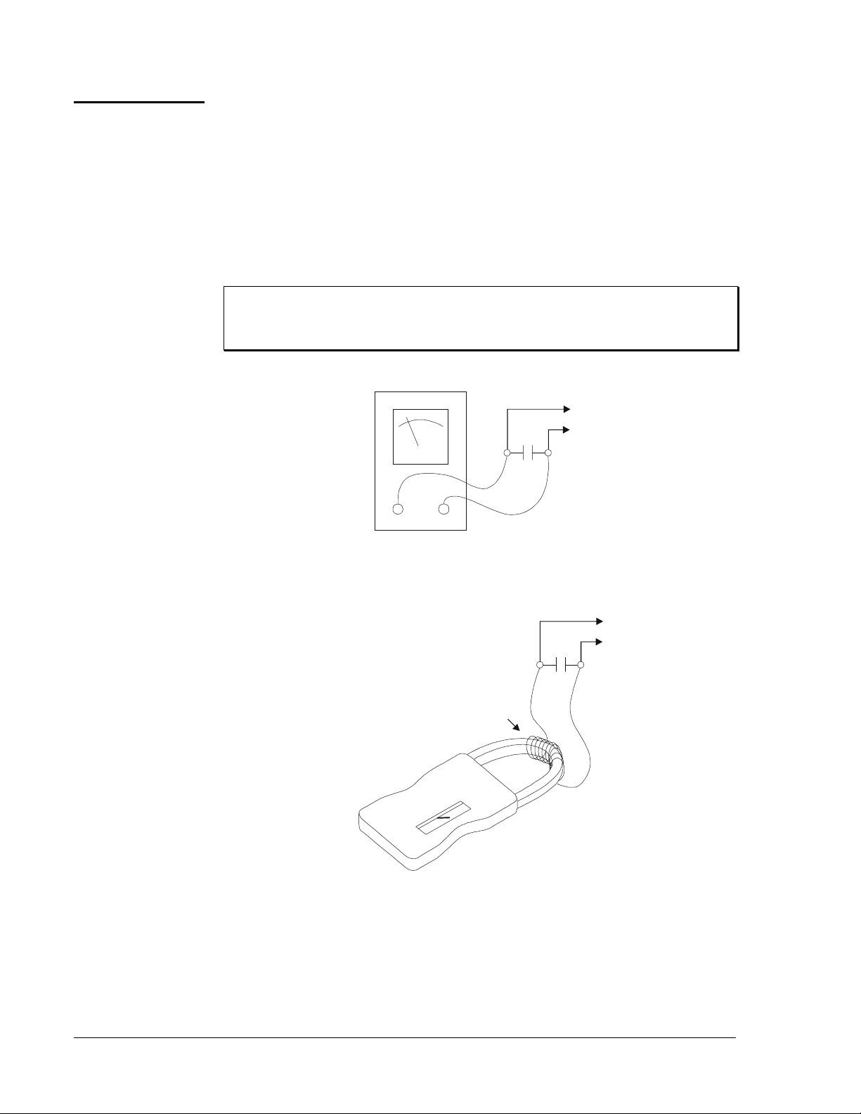
Due to variations in appliance wiring and valves, it is advisable to measure
the actual current draw of the heating system at the thermostat location.
Measuring this current can be accomplished by opening the thermostat
contacts (lowering the set point) and installing an AC ammeter across the
terminals, or by using a clamp-on ammeter with a 10-turn multiplier
attached to the terminals (see Figure 10).
IMPORTANT: Measuring the current with an ammeter will energize
the system. Wait until the gas valve and inducer
energize before taking a current draw measurement.
To
Heating
System
WR
AC Ammeter Low Scale Setting
To
Heating
System
WR
Ten Turns
Clamp-on Ammeter
(Divide reading by ten.)
Figure 10: Measuring the Thermostat Current
10 G
G670 Intermittent Pilot Ignition Controls Technical Bulletin
Page 11

Troubleshooting Procedure
If the system does not function properly, determine the cause using the
procedures in this section.
Preliminary
Checks
Failure
Conditions and
Corrective
Action
Repairs and Replacement
Before proceeding with troubleshooting the system, check the following:
• Are all mechanical and electrical connections tight?
• Is the system wired correctly?
• Is the gas inlet pressure per the manufacturer’s specifications?
• Is the system powered?
• Is the thermostat calling for heat?
There are three potential system failure conditions:
• no spark, and system does not work
• spark is present, but pilot does not light
• pilot lights, but main valve does not come on
Determine the failure condition, then use the respective flowcharts on the
following pages to troubleshoot the system. Perform the procedures in the
Checkout and Startup Procedure section after any servicing.
!
CAUTION: Label all wires prior to disconnection when servicing
controls. Wiring errors can cause improper and
dangerous operation. Verify proper operation after
servicing.
Do not attempt field repairs. Use only exact or factory recommended
replacement controls.
All other accessories, such as flame sensors, electrode assemblies, pilot
assemblies, and leads can be obtained through the original equipment
manufacturer or a Johnson Controls distributor.
G670 Intermittent Pilot Ignition Controls Technical Bulletin
G
11
Page 12

Start
Visually
check. Is Lead 5
connected securely
to ground?
Are thermostat
and limit contacts
closed?
Close
contacts
Check for proper
voltage at transformer
primary and secondary
In some instances a
Note:
jumper is used between
Terminals 2 and 6
to power Terminal 6.
Ye s
No
Repair
No
Connect
securely
Ye s
Ye s
Is 24 VAC present
between Terminal 2
and ground?
No
Is circuit wiring
providing 24 VAC to
wiring providing 24 VAC
to Terminal 6?
No
Terminal 2?
Ye s
Is circuit
No
Repair
Ye s Ye s
Is 24 VAC present
between Terminal 6
and ground?
No
Is 24 VAC present
between Terminal 1
and ground?
supply voltage
Ye s
Turn off
No
Replace
G670
Ye s
Replace
G670
Replace
cable
Is spark gap
0.1 in. and located in
pilot gas stream?
No
Correct or replace
pilot burner
No
No
Is high voltage
cable in good condition
(not brittle, burnt, or
cracked)?
Is spark
electr ode ceramic
cracked?
Replace pilot
burner
Turn on
supply voltage
Ye s
Ye s
Ye s
Operate system
several complete
Is high voltage
cable connected to spark
transformer?
Connect
securely
Turn on
supply voltage
cycles
Figure 11: No Spark, and System Does Not Work
No
End
12 G
G670 Intermittent Pilot Ignition Controls Technical Bulletin
Page 13

Start
Is pilot valve wiring
securely connected to
Terminal 1 and
ground ?
Ye s
No
Connect
securely
Is 24 VAC present
between Terminal 1
and ground?
Ye s
Is inlet gas pressure
per manufacturer’s
specifications?
No
Correct gas
pressure
No
Replac e
G670
Ye s
Is gas at pilot?
Is pilot spark gap
0.1 in. and located in
pilot gas stream?
Check for drafts. Shield
as necessary and check
for clean orifice.
Ye s
Ye s
!
WARNING:
No
No
Explosion Hazard.
Do not use a match to
test for presence of gas.
Make sure pilot line is not
kinked or obstructed. Check
for clean orifice.
Replac e
pilot valve
Correct or
replace pilot
End
Figure 12: Spark is Present, but Pilot Does Not Light
G670 Intermittent Pilot Ignition Controls Technical Bulletin
G
13
Page 14

Start
Does spark stay on
for more than 30 seconds
after the pilot lights?
No
Is 24 VAC
between Terminal 3
and ground?
Ye s
Is inlet gas pressure
per manufacturer’s
specifications?
No
gas pressure
Correct
Ye s
Make sure sensor cable
and high voltage cable are
separated and not wrapped
around any pipe or accessories.
Is sensor cable
securely connected
to Terminal 4 and
flame sensor?
Ye s
Is sensor
ceramic cracked?
Ye s
Replace
sensor
No
No
Replace
Connect
securely
grounded out ?
No
G670
Is cable
Correct
Ye s
securely connected to
Terminal 3 and
No
sensor connector
shorted out to metal
continuity and good
insulation in the
Ye s
Is main
valve wiring
ground?
Ye s
Replace
main valve
Is sensor or
surface?
No
Is there
sensor cable?
No
Ye s
No
Connect
securely
Correct
Replace
cable
14 G
Connect DC microammeter
between sensor cable terminal and
Terminal 4. Observe correct polarity.
See Figure 20.
Is DC current
0.2 microamperes or
greater with pilot only
operation?
Ye s
Replace
G670
No
Disconnect sensor
cable from Terminal 4
Check for:
- proper gas pressure
- clean pilot assembly
- tight mechanical and electrical connections
If there is not improvement, change the
flame sensor length or the orifice size and
perform any necessary turn down tests.
Figure 13: Pilot Lights, but Main Burner Does Not Come On
G670 Intermittent Pilot Ignition Controls Technical Bulletin
Ye s
Disconnect main valve
lead from Terminal 3
End
Page 15

Start
Is system wiring
per manufacturer’s
instructions?
Ye s
Open thermostat
contacts for
30 seconds
Correct
wiring
No
Is 24 VAC present
between Terminal 2
and ground?
No
Is 24 VAC present
on secondary
of transformer?
No
Replace the transformer if
proper voltage is present
on primary of transformer.
Replace the Y79 with
the appropriate
G600 Ignition controls
(contact Johnson Controls
Technical Support).
Ye s
Ye s
No
Reset
high limit
No
Is a
spark
present?
Ye s
Is 24 VAC present
between Terminal 1
Is high
limit
closed?
Ye s
System was
and ground?
No
Replace
G670
Ye s
Replace
G670
Close thermostat
contacts and wait 30%
of the Y79 lockout time
in lockout
Ye s
Connect
securely
Turn supply
voltage on
Replace
cable
Is spark gap
0.1 in. and
located in pilot
gas stream?
No
Correct or
replace pilot
burner
Determine reason f or lockout.
Conduct microamperage test as
outlined in Figure 16,
starting at A .
Turn off supply voltage
No
No
Turn supply voltage on
Check the high voltage
cable. Is it securely
connected to the spark
transformer?
Is condition of high
voltage cable good
(not brittle, burnt,
or cracked)?
No
Is spark
electr ode
ceramic cracked?
Replace
pilot burner
Ye s
Ye s
Ye s
Operate system several complete cycles
Figure 14: G670/Y79B No Spark, and System Does Not Work
G670 Intermittent Pilot Ignition Controls Technical Bulletin
G
End
15
Page 16

Start
Are pilot valve and
main valve connections
secured to the proper Y79
terminal and ground?
Ye s
Open thermostat contacts
for 30 seconds
Replace the Y79 with
the appropriate
G600 ignition control
(contact Johnson Controls
Technical Support).
Correct
No
Connect securely
Is 24 VAC present
between ground and
pilot valve terminals
No
No
of Y79?
Ye s
Is inlet
pressure per
manufacturer’s
specifications?
Ye s
Ye s
!
WARNING:
Close thermostat
contacts
Is 24 VAC present
between Terminal 1
and ground on the G670?
Wait 30% of the Y79
lockout time.
No
Replace
G670
Explosion Hazard.
Do not use a match to
test for presence of gas.
16 G
Is gas
at pilot?
No
Make sure the pilot line is not
kinked or obstructed. Check
for a clean orifice.
If OK, replace pilot valve.
Ye s
Is spark gap
0.1 in. and located in
the pilot gas stream?
No
Correct or replace
pilot burner
Figure 15: G670/Y79B Spark is Present, but Pilot Does Not Light
G670 Intermittent Pilot Ignition Controls Technical Bulletin
Ye s
Check for drafts.
Shield as necessary and
check for clean orifice.
End
Page 17

Start
Does spark stay on
for more than 30 seconds
after pilot lights?
No
Is 24 VAC
between Terminal 3
and ground?
Ye s
Is inlet gas pressure
per manufacturer’s
specifications?
No
Correct
gas pressure
Ye s
Make sure sensor cable
and high voltage cable are
separated and not wrapped
around any pipe or accessories.
Is sensor cable
securely connected
to Terminal 4 and
flame sensor?
Ye s
Is sensor
ceramic cracked?
Ye s
Replace
sensor
No
Connect
securely
No
Is cable
grounded out ?
Replace
Ye s
G670
No
Is 24 VAC present between
main valve terminal on the Y79
and ground terminal on the G670?
Is main valve wiring
securely connected to
the main valve terminal
on the Y79 and ground?
No
Is sensor or
sensor connector
shorted out to metal
surface?
No
Ye s
Ye s
Ye s
No
Replace the Y79 with
the appropriate
G600 ignition control
(contact Johnson Controls
Technical Support).
No
Connect
securely
Replace
main valve
Ye s
Correct
Connect DC microammeter
between sensor cable terminal and
Terminal 4. Observe correct polarity.
See Figure 20.
Is DC current
0.2 microamperes or
greater with pilot only
operation?
Replace
G670
Correct
Disconnect sensor
cable from Terminal 4
Check for:
- proper gas pressure
- clean pilot assembly
No
- tight mechanical and electrical connections
If there is no improvement, change the flame
sensor length or the orifice size, then perform
any necessary turn down tests.
Is there
continuity and good
insulation in the
sensor cable?
Ye s
Disconnect main valve
lead from Terminal 3
No
Replace
cable
End
Figure 16: G670/Y79B Pilot Lights, but Main Burner Does Not Come On
A
G670 Intermittent Pilot Ignition Controls Technical Bulletin
G
17
Page 18

Start
Is system wiring
per manufacturer’s
instructions?
Ye s
Open thermostat
contact for
30 seconds
Correct
wiring
Is 24 VAC present
between Terminal 2
and ground?
No
Is 24 VAC present
on secondary
of transformer?
No
Replace transformer if
proper voltage is present
on primary of transformer
Reset
high limit
No
No
Ye s
Ye s
No
Is a
spark
present?
Ye s
Is high
limit
closed?
contacts and wait 30%
of the Y79 lockout time
System was
in lockout
Is 24 VAC
present between
Terminal 1
and ground?
No
Replace
G670
Close thermostat
Ye s
Connect
securely
Turn supply
voltage on
Replace
cable
Determine the reason for lockout.
Conduct microamperage test as
outlined in Figure 16,
starting at A .
Turn off supply voltage
No
No
Check the high voltage
cable. Is it securely
connected to the spark
transformer?
Ye s
Is condition of high
voltage cable good
(not bri ttle, burnt,
or cracked)?
Ye s
18 G
Ye s
Replace the Y79 with
the appropriate
G600 ignition control
(contact Johnson Controls
Technical Support).
End
Operate system several complete cycles
Ye s
located in pilot
Replace
G670
replace pilot
Figure 17: G670/Y79A No Spark, and System Does Not Work
G670 Intermittent Pilot Ignition Controls Technical Bulletin
Is spark gap
0.1 in. and
gas stream?
No
Correct or
burner
No
electr ode ceramic
cracked?
pilot burner
Turn supply voltage on
Is spark
Ye s
Replace
Page 19

Start
Is pilot valve wiring
securely connected to
Terminal 1 and
ground ?
Ye s
Is inlet gas pressure
per manufacturer’s
specifications?
No
Ye s
Connect
securely
Is gas at pilot?
!
WARNING:
No
Explosion Hazard.
Do not use a match to
test for presence of gas.
Make sure pilot line is not
kinked or obstructed. Check
for clean orifice.
No
Correct gas
pressure
Is pilot spark gap
0.1 in. and located in
pilot gas stream?
Check for drafts. Shield
as necessary and check
Ye s
Ye s
for clean orifice.
No
Replac e
pilot valve
Correct or
replace pilot
End
Figure 18: G670/Y79A Spark is Present, but Pilot Will Not Light
G670 Intermittent Pilot Ignition Controls Technical Bulletin
G
19
Page 20

Start
Does spark stay on
for more than 30 seconds
after the pilot lights?
No
Is 24 VAC
between Terminal 3
and ground?
Ye s
Is inlet gas pressure
per manufacturer’s
specifications?
No
gas pressure
Correct
Ye s
Make sure sensor cable
and high voltage cable are
separated and not wrapped
around any pipe or accessories.
Is sensor cable
securely connected
to Terminal 4 and
flame sensor?
Ye s
Is sensor
ceramic cracked?
Ye s
Replace
sensor
No
No
Replace
Connect
securely
grounded out ?
No
G670
Is cable
Correct
Ye s
securely connected to
Terminal 3 and
No
sensor connector
shorted out to metal
continuity and good
insulation in the
Ye s
Is main
valve wiring
ground?
Ye s
Replace
main valve
Is sensor or
surface?
No
Is there
sensor cable?
No
Ye s
No
Connect
securely
Correct
Replace
cable
20 G
Ye s
Connect DC microammeter
between sensor cable terminal and
Terminal 4. Observe correct polarity.
See Figure 20.
Is DC current
0.2 microamperes or
greater with pilot only
operation?
Ye s
Replace
G670
No
Disconnect sensor
cable from Terminal 4
Check for:
- proper gas pressure
- clean pilot assembly
- tight mechanical and electrical connections
If there is not improvement, change the
flame sensor length or the orifice size and
perform any necessary turn down tests.
Disconnect main valve
lead from Terminal 3
End
Figure 19: G670/Y79A Pilot Lights, but Main Burner Does Not Come On
G670 Intermittent Pilot Ignition Controls Technical Bulletin
Page 21
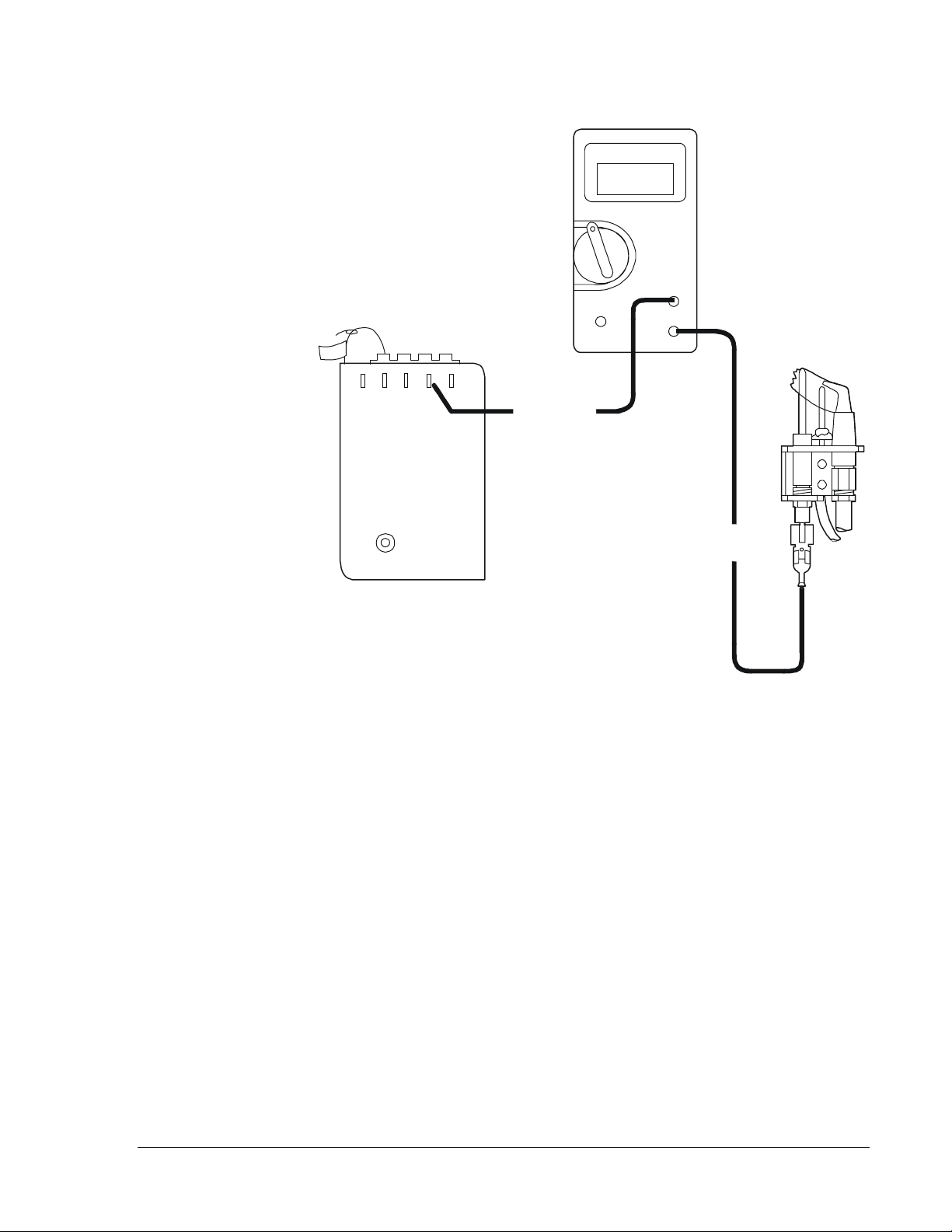
Y99AU-2 Multimeter
Jumper
5
62
1
43
Positive Lead
to Terminal 4
Negative Lead
to Flame Sensor
Pilot Burner
Assembly
Figure 20: Meter Hookup to Measure Flame Sensing Circuit
Electrode
G670 Intermittent Pilot Ignition Controls Technical Bulletin
G
21
Page 22

Notes
22 G
G670 Intermittent Pilot Ignition Controls Technical Bulletin
Page 23

Notes
G670 Intermittent Pilot Ignition Controls Technical Bulletin
G
23
Page 24

Notes
Controls Group www.johnsoncontrols.com
507 E. Michigan Street
P.O. Box 423 Installation Sheets Manual
Milwaukee, WI 53201 Printed in U.S.A.
24 G
G670 Intermittent Pilot Ignition Controls Technical Bulletin
FAN 121
 Loading...