

Johnson Controls (H, Y, C)IDM030B21E, C)IDM036B21E, C)IDM048B21E Installation And Maintenance Manual
...
PMGB0400B-rev.2
Installation
and
Maintenance
Manual
INVERTER-DRIVEN
MULTI-SPLIT SYSTEM
HEAT PUMP
AIR CONDITIONERS
IMPORTANT:
READ AND UNDERSTAND
THIS MANUAL BEFORE
USING THIS HEAT PUMP
AIR CONDITIONER.
KEEP THIS MANUAL FOR
FUTURE REFERENCE.
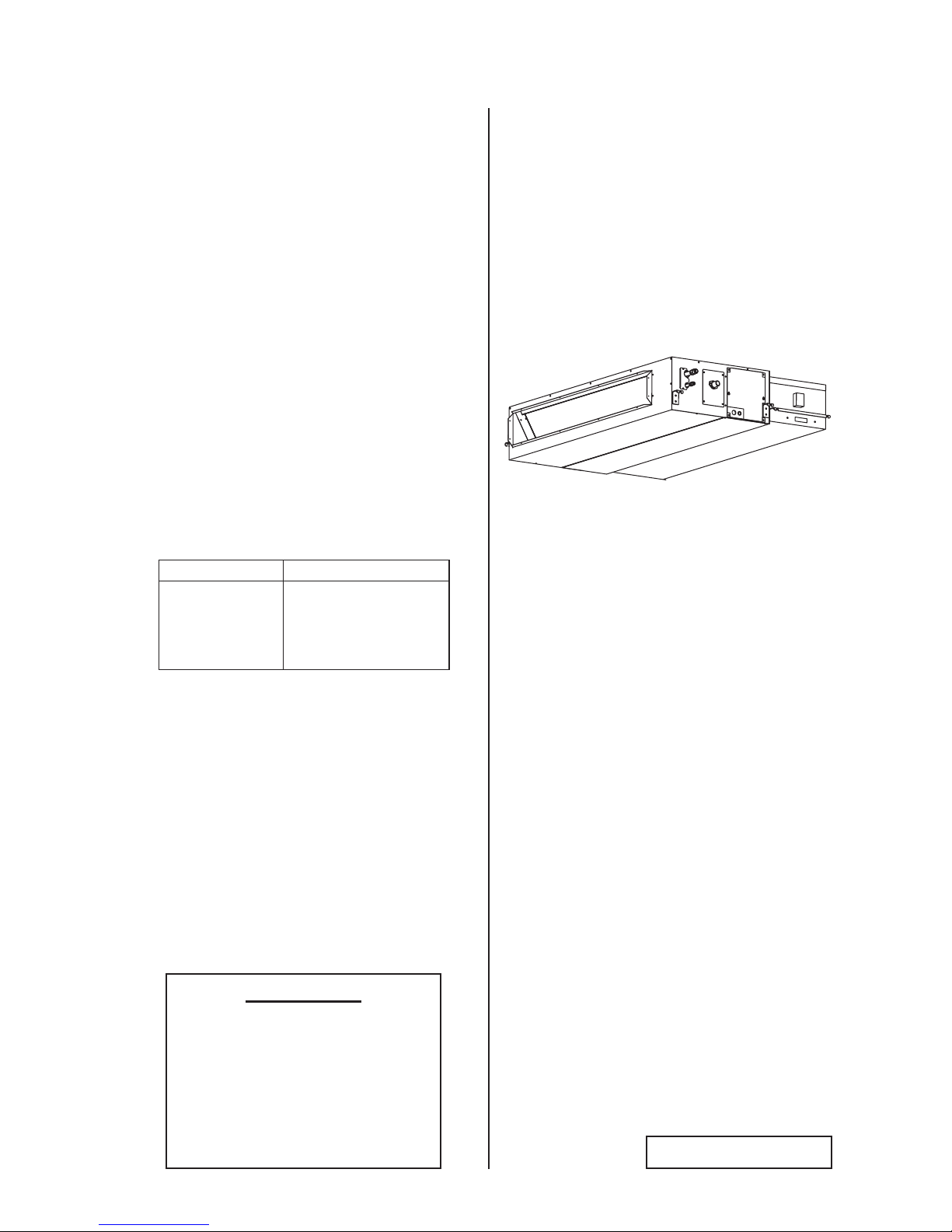
Type Model
Ducted
(Medium Static)
with
EconoFresh Kit
(H,Y,C)IDM030B21E
(H,Y,C)IDM036B21E
(H,Y,C)IDM048B21E
with
EF-456NE


PMGB0400B-rev.2
i
Important Notice
● Johnson Controls Inc. pursues a policy of continuing improvement in design and performance in its
products. As such, Johnson Controls Inc. reserves the right to make changes at any time without
prior notice.
● Johnson Controls Inc. cannot anticipate every possible circumstance that might involve a potential hazard.
● This heat pump air conditioning unit is designed for standard air conditioning applications only. Do
not use this unit for anything other than the purposes for which it was intended for.
● The installer and system specialist shall safeguard against leakage in accordance with local
pipetter and electrical codes. The following standards may be applicable, if local regulations are
not available. International Organization for Standardization: (ISO 5149 or European Standard, EN
378). No part of this manual may be reproduced in any way without the expressed written consent of
Johnson Controls Inc.
● This heat pump air conditioning unit will be operated and serviced in the United States of America
and comes with a full complement of the appropriate Safety, Danger, and Caution, Warnings.
● If you have questions, please contact your distributor or dealer.
● This manual provides common descriptions, basic and advanced information to maintain and service
this heat pump air conditioning unit which you operate as well for other models.
● This heat pump air conditioning unit has been designed for a specic temperature range. For optimum
performance and long life, operate this unit within the range limits.
● This manual should be considered as a permanent part of the air conditioning equipment and should
remain with the air conditioning equipment.
Product Inspection upon Arrival
1. Upon receiving this product, inspect it for any damages incurred in transit. Claims for damage, either
apparent or concealed, should be led immediately with the shipping company.
2. Check the model number, electrical characteristics (power supply, voltage, and frequency rating),
and any accessories to determine if they agree with the purchase order.
3. The standard utilization for this unit is explained in these instructions. Use of this equipment for
purposes other than what it designed for is not recommended.
4. Please contact your local agent or contractor as any issues involving installation, performance, or
maintenance arise. Liability does not cover defects originating from unauthorized modications
performed by a customer without the written consent of Johnson Controls, Inc. Performing any
mechanical alterations on this product without the consent of the manufacturer will render your
warranty null and void.

ii
PMGB0400B-rev.2
TABLE OF CONTENTS
1. Introduction .....................................................................................................................................................1
2. Safety Instructions ...........................................................................................................................................1
3. Before Installation ...........................................................................................................................................7
3.1 Combination of Outdoor Unit and Indoor Unit ........................................................................................7
3.2 Working Range .......................................................................................................................................7
3.3 Transportation and Handling ..................................................................................................................9
3.4 Factory-Supplied Accessories ................................................................................................................ 9
3.5 Necessary Tools and Instrument List for Installation ..............................................................................9
4. Installation Location ......................................................................................................................................10
5. Installation Work ...........................................................................................................................................11
5.1 Positions of Suspension Bolts and Piping Connections ....................................................................... 11
5.2 Installation of Suspension Bolts ........................................................................................................... 11
5.3 Mounting Indoor Unit ............................................................................................................................12
5.4 Adjusting Level of Unit ..........................................................................................................................13
5.5 Ducting Arrangement ............................................................................................................................13
5.5.1 Pressure Drop of Outdoor Air Duct .............................................................................................13
5.5.2 Pressure Relief Damper ............................................................................................................. 13
5.6 Example of Installation .........................................................................................................................14
5.6.1 Ducting Connection .................................................................................................................... 14
5.6.2 Insulation ....................................................................................................................................14
5.7 Connecting Supply Duct .......................................................................................................................15
5.8 Setting the EconoFresh Pressure Mode ..............................................................................................16
6. Refrigerant Piping Work ................................................................................................................................17
6.1 Piping Materials ....................................................................................................................................17
6.2 Piping Connection Work .......................................................................................................................18
7. Drain Piping ..................................................................................................................................................20
8. Electrical Wiring ............................................................................................................................................22
8.1 General Check .....................................................................................................................................22
8.2 Electrical Wiring Capacity .....................................................................................................................23
8.2.1 Field Minimum Wire Sizes for Power Supply .............................................................................. 23
8.2.2 Details of Electrical Wiring Connection ....................................................................................... 23
8.3 Position of Electrical Wiring Connection ...............................................................................................25
8.4 Wiring Connections ..............................................................................................................................28
8.5 DIP Switch Settings ..............................................................................................................................29
8.6 EconoFresh Pressure Mode Setting ....................................................................................................30
8.7 Function Selection by Wired Controller ................................................................................................31
9. Test Run ........................................................................................................................................................32
9.1 Before Test Run .................................................................................................................................... 32
9.2 Test Run ...............................................................................................................................................32
9.3 Alarm Code ..........................................................................................................................................34
PMGB0400B-rev.2
1
● For details on wiring between the indoor unit and the outdoor unit, refer to the "Installation and Maintenance
Manual" for the outdoor unit.
● For details on the econofresh kit, refer to the "Installation Manual" for the econofresh kit.
● For details on the optional controller, refer to the "Installation and Maintenance Manual" for that optional
controller module.
● For details on each optional part, refer to the "Installation and Maintenance Manual" for each optional part.
● For central station, refer to the "Installation and Maintenance Manual" for the central station.
1. Introduction
Forward this information, and the warranty to all installers and users. Ask end users to maintain copies for future
reference.
(Refrigerant Piping Work) (Electrical Wiring Work) (Ref. Charge Work) (Test Run) (User)
2. Safety Instructions
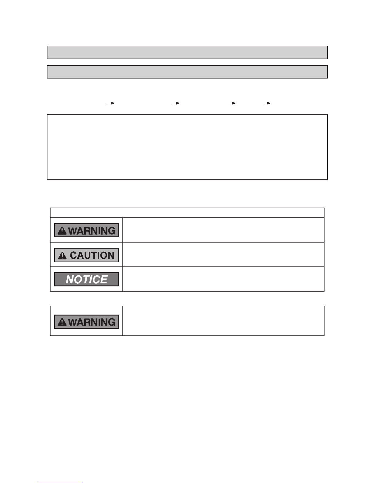
Signal Words
Indicates a hazardous situation that, if not avoided, could result in death
or serious injury.
Indicates a hazardous situation that, if not avoided, could result in minor or
moderate injury.
Indicates information considered important, but not hazard-related (for
example, messages relating to property damage).
General Precautions
To reduce the risk of serious injury or death, read these instructions
thoroughly and follow all warnings or cautions included in all manuals
that accompanied the product and are attached to the unit. Refer back to
these safety instructions as needed.
● This system should be installed by personnel certied by Johnson Controls, Inc. Personnel must be
qualied according to local, state and national building and safety codes and regulations. Incorrect
installation could cause leaks, electric shock, re or explosion. In areas where Seismic ‘’Performance
requirements are specied, the appropriate measures should be taken during installation to guard
against possible damage or injury that might occur in an earthquake if the unit is not installed
correctly, injuries may occur due to a falling unit.
● Use appropriate Personal Protective Equipment (PPE), such as gloves and protective goggles and,
where appropriate, have a gas mask nearby. Also use electrical protection equipment and tools
suited for electrical operation purposes. Keep a quenching cloth and a re extinguisher nearby during
brazing. Use care in handling, rigging, and setting of bulky equipment.
● When transporting, be careful when picking up, moving and mounting these units. Although the
unit may be packed using plastic straps, do not use them for transporting the unit from one location
to another. Do not stand on or put any material on the unit. Get a partner to help, and bend with
your knees when lifting to reduce strain on your back. Sharp edges or thin aluminum ns on the air
conditioner can cut ngers, so wear protective gloves.
Read following sections carefully before installing this product.
Read over the "Installation and Maintenance Manual" for the outdoor unit as well.
2
PMGB0400B-rev.2
● Do not touch or adjust any safety devices inside the indoor or outdoor units. All safety features,
disengagement, and interlocks must be in place and functioning correctly before the equipment is put
into operation. If these devices are improperly adjusted or tampered with in any way, a serious accident
can occur. Never bypass or jump-out any safety device or switch.
● Before servicing, turn-OFF the power supply and use accepted lockout and tag out procedures at all
main switches.
● This unit is the pressurized system. Never loosen threaded joints while the system is under pressure
and never open pressurized system parts.
● Johnson Controls will not assume any liability for injuries or damage caused by not following steps
outlined or described in this manual. Unauthorized modications to Johnson Controls products are
prohibited as they…
◦ May create hazards which could result in death, serious injury or equipment damage;
◦ Will void product warranties;
◦ May invalidate product regulatory certications;
◦ May violate OSHA standards;
Take the following precautions to reduce the risk of property damage.
● Be careful that moisture, dust, or variant refrigerant compounds not enter the refrigerant cycle during
installation work. Foreign matter could damage internal components or cause blockages.
● If air lters are required on this unit, do not operate the unit without the air lter set in place. If the air
lter is not installed, dust may accumulate and breakdown may result.
● Do not install this unit in any place where silicon gases can coalesce. If the silicon gas molecules
attach themselves to the surface of the heat exchanger, the nned surfaces will repel water. As a
result, any amount of drainage moisture condensate can overow from the drain pan and could run
inside of the electrical box, possibly causing electrical failures.
● When installing the unit in a hospital or other facility where electromagnetic waves are generated
from nearby medical and/or electronic devices, be prepared for noise and electronic interference
Electromagnetic Interference (EMI). Do not install where the waves can directly radiate into the
electrical box, controller cable, or controller. Inverters, appliances, high-frequency medical equipment,
and radio communications equipment may cause the unit to malfunction. The operation of the unit
may also adversely affect these same devices. Install the unit at least 10 ft. (3m) away from such
devices.
● When a wireless controller is used, locate at a distance of at least 3.3 ft. (1m) between the indoor
unit and electric lighting. If not, the receiver part of the unit may have difculty receiving operation
commands.
● Do not install the unit in any location where animals and plants can come into direct contact with the
outlet air stream. Exposure could adversely affect the animals and plants.
● Do not install the unit with any downward slope to the side of the drain adaptor. If you do, you may
have drain water owing back which may cause leaks.
● Be sure the drain hose discharges water properly. If connected incorrectly, it may cause leaks.
● Do not install the unit in any place where oil can seep onto the units, such as table or seating areas in
restaurants, and so forth. For these locations or social venues, use specialized units with oil-resistant
features built into them. In addition, use a specialized ceiling fan designed for restaurant use. These
specialized oil-resistant units can be ordered for such applications. However, in places where large
quantities of oil can splash onto the unit, such as a factory, even the specialized units cannot be used.
These products should not be installed in such locations.
Installation Precautions
To reduce the risk of serious injury or death, the following installation
precautions must be followed.
● When installing the unit into…
▫ A wall: Make sure the wall is strong enough to hold the unit’s weight. It may be necessary to
construct a strong wood or metal frame to provide added support.
▫ A room: Properly insulate any refrigerant tubing run inside a room to prevent “sweating” that can
cause dripping and water damage to wall and oors.

PMGB0400B-rev.2
3
▫ Damp or uneven areas: Use a raised concrete pad or concrete blocks to provide a solid, level
foundation for the unit to prevent water damage and abnormal vibration.
▫ An area with high winds: Securely anchor the outdoor unit down with bolts and a metal frame.
Provide a suitable air bafe.
▫ A snowy area: Install the outdoor unit on a raised platform that is higher than drifting snow. Provide
snow vents.
● Do not install the unit in the following places. Doing so can result in an explosion, re, deformation,
corrosion, or product failure.
▫ Explosive or ammable atmosphere
▫ Where a re, oil, steam or powder can directly enter the unit, such as nearby or above a kitchen
stove.
▫ Where oil (including machinery oil) may be present.
▫ Where corrosive gases such as chlorine, bromine, or sulde can accumulate, such as near a hot
tub or a hot spring.
▫ Where dense, salt-laden airow is heavy, such as in coastal regions.
▫ Where the air quality is of high acidity.
▫ Where harmful gases can be generated from decomposition.
● Do not position the drain pipe for the indoor unit near any sanitary sewers where corrosive gases
may be present. If you do, toxic gases can seep into breathable air spaces and can cause respiratory
injuries. If the drain pipe is installed incorrectly, water leakage and damage to the ceiling, oor,
furniture, or other possessions may result. If the drain pipe becomes clogged, water may drip from the
indoor unit. Do not install the indoor unit where such dripping can cause moisture damage or uneven
locations: Use a raised concrete pad or concrete blocks to provide a solid, level foundation for the unit
to prevent water damage and abnormal vibration.
● Before performing any brazing work, be sure that there are no ammable materials or open ames
nearby.
● Perform a test run to ensure normal operation. Safety guards, shields, barriers, covers, and protective
devices must be in place while the compressor/unit is operating. During the test run, keep ngers and
clothing away from any moving parts.
● Clean up the site when nished, remembering to check that no metal scraps or bits of wiring have
been left inside the unit being installed.
After installation work for the system has been completed, explain the “Safety Precautions,” the proper use
and maintenance of this unit to the customer according to the information in all manuals that came with the
system. All manuals and warranty information must be given to the user or left near the Indoor Unit.
4
PMGB0400B-rev.2
Refrigerant Precautions
To reduce the risk of serious injury or death, the following refrigerant
precautions must be followed.
● As originally manufactured, this unit contains refrigerant installed by Johnson Controls. Johnson
Controls uses only refrigerants that have been approved for use in the unit’s intended home country
or market. Johnson Controls distributors similarly are only authorized to provide refrigerants that
have been approved for use in the countries or markets they serve. The refrigerant used in this unit
is identied on the unit’s faceplate and/or in the associated manuals. Any additions of refrigerant into
this unit must comply with the country’s requirements with regard to refrigerant use and should be
obtained from Johnson Controls distributors. Use of any non-approved refrigerant substitutes will void
the warranty and will increase the potential risk of injury or death.
● If installed in a small room, take measures to prevent the refrigerant from exceeding the maximum
allowable concentration in the event that refrigerant gases should escape. Refrigerant gases can
cause asphyxiation (0.026 lbs/ft
3
(0.42 kg/m3) based on ISO 5149 for R410A). Consult with your
distributor for countermeasures (ventilation system and so on). If refrigerant gas has leaked during the
installation work, ventilate the room immediately.
● Before installation is complete, make sure that the refrigerant leak test has been performed. If
refrigerant gases escape into the air, turn OFF the main switch, extinguish any open ames and
contact your service contractor. Refrigerant (Fluorocarbon) for this unit is odorless. If the refrigerant
should leak and come into contact with open ames, toxic gas could be generated. Also, because the
uorocarbons are heavier than air, they settle to the oor, which could cause asphyxiation.
● When installing the unit, and connecting refrigerant piping, keep all piping runs as short as possible,
and make sure to securely connect the refrigerant piping before the compressor starts operating. If
the refrigerant piping is not connected and the compressor activates with the stop valve opened, the
refrigerant cycle will become subjected to extremely high pressure, which can cause an explosion or re.
● Tighten the are nut with a torque wrench in the specied manner. Do not apply excessive force to the
are nut when tightening. If you do, the are nut can crack and refrigerant leakage may occur.
● A compressor/unit comprises a pressurized system. Never loosen threaded joints while the system is
under pressure and never open pressurized system parts.
● When maintaining, relocating, and disposing of the unit, dismantle the refrigerant piping after the
compressor stops.
Electrical Precautions
Take the following precautions to reduce the risk of electric shock, re or
explosion resulting in serious injury or death.
● Highly dangerous electrical voltages are used in this system. Carefully refer to the wiring diagram and
these instructions when wiring. Improper connections and inadequate grounding can cause serious
injury or death.
● Before servicing, open and tag all disconnect switches. Never assume electrical power is
disconnected. Check with meter and equipment.
● Only use electrical protection equipment and tools suited for this installation.
● Use specied cables between units.
● Communication cable should be a minimum of AWG18 (0.82mm
2
), 2-Conductor, Stranded Copper.
Shielded cable must be considered for applications and routing in areas of high EMI and other
sources of potentially excessive electrical noise to reduce the potential for communication errors.
When shielded cable is applied, proper bonding and termination of the cable shield is required as per
Johnson Controls guidelines. Plenum and riser ratings for communication cables must be considered
per application and local code requirements.
● Use an exclusive power supply for the air conditioner at the unit’s rated voltage.
● Be sure to install circuit breakers (ground fault interrupter, isolating switch, molded case circuit
breaker and so on), with the specied capacity. Ensure that the wiring terminals are tightened
securely to recommended torque specications. If a circuit breaker or fuse is frequently activated,
shut down the system and contact your service contractor.

PMGB0400B-rev.2
5
● Clamp electrical wires securely with a cable clamp after all wiring is connected to the terminal block.
In addition, run wires securely through the wiring access channel.
● When installing the power lines, do not apply tension to the cables. Secure the suspended cables at
regular intervals, but not too tightly.
● Make sure that the terminals do not come into contact with the surface of the electrical box. If the
terminals are too close to the surface, it may lead to failures at the terminal connection.
● Turn OFF and disconnect the unit from the power supply when handling the service connector. Do not
open the service cover or access panel to the indoor or outdoor units without turning OFF the main
power supply.
● After stopping operation, be sure to wait at least ve minutes before turning off the main power
switch. Otherwise, water leakage or electrical breakdown may result. Disconnect the power supply
completely before attempting any maintenance for electrical parts. Check to ensure that no residual
voltage is present after disconnecting the power supply.
● Do not clean with, or pour water into, the controller as it could cause electric shock and/or damage the
unit. Do not use strong detergent such as a solvent. Clean with a soft cloth.
● Check that the ground wiring is securely connected. Do not connect ground wiring to gas piping,
water piping, lighting conductor, or telephone ground wiring.
● If a circuit breaker or fuse is frequently activated, shut down the system and contact your service
contractor.
● This equipment can be installed with a Ground Fault Circuit Breaker (GFCI), which is a recognized measure for
added protection to a properly grounded unit. Install appropriate sized breakers / fuses / overcurrent protection
switches, and wiring in accordance with local, state and NEC codes and requirements. The equipment installer
is responsible for understanding and abiding by applicable codes and requirements.
6
PMGB0400B-rev.2
● Proper handling of this unit requires two people. Safe handling and installing of the indoor unit requires
the strength of two people. Mounting the unit alone may cause injury due to a fall of the unit. Although
the unit may be girded with steel banding, do not use it for transportation. Avoid contact with nned
surfaces of the heat exchanger as sharp edges can cause severe injury to hands and ngers. Use
appropriate work gloves for the job.
NOTICE
● Check to ensure that the drain hose discharges moisture properly. If connected incorrectly, it can result in
leakage and damage to furniture.
● Do not apply an excessive force to the drain pipe connection. This can also compromise the seal
properties of the connection.
● Verify that the installed unit is level with oor and ceiling surfaces. Any variance or inclination can cause
moisture to back up into the drain pan, overow, and seepage onto ceiling or wall surfaces, and cause
damage to carpeted surfaces or furniture below.
● Do not install this system in close proximity to septic sewer lines where ammable and toxic gases can coalesce.
● Inspect the drain pan before the onset of winter to drain away all accumulated moisture in the pan.
● The heat exchanger of indoor unit overheats whenever there is a slight amount of refrigerant circulating
during slowdown or stoppage. As a result, moisture in the drain pan evaporates where it can condense on
ceiling or wall surfaces.
● After the drain check is completed, insert the rubber plug again and seal the gap with a silicone sealant.
Electrical Installation
In some cases, the packaged air conditioner may not be operated normally under the following cases:
● When electrical power for the packaged air conditioner is supplied from the same power transformer
as the device*.
● When the power supply wiring for the device* and the packaged air conditioner are located close to
each other:
Device*(Example): Lift, container crane, rectier for electric railway, inverter power device, arc
furnace, electric furnace, large-sized induction motor, and large-sized switch.
It consumes large quantities of electrical power.
Regarding that mentioned above, surge voltage may be inducted into the power supply wiring for the crated
air conditioner due to a spike in power consumption for this device and an activation of the switch. Check
the eld regulations and standards before performing any electrical work in order to safeguard the power
supply for the crated air conditioning unit.
PMGB0400B-rev.2
7
3. Before Installation
NOTES:
● If the Damper Minimum Setting (optional function d7) of this indoor unit is set to higher step then this will
affect the air outlet temperature of other standard indoor units.
● Airow volume must be at lower limit for All Fresh operation.
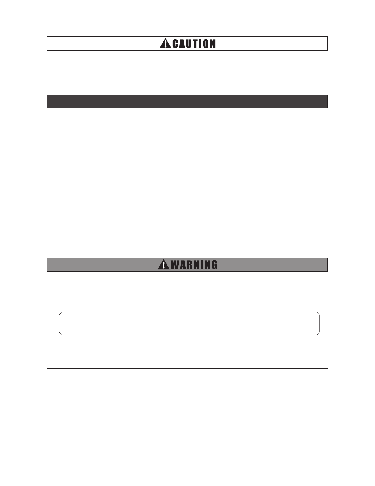
3.2 Working Range
This heat pump air conditioner has been designed for the following temperatures. Operate the heat pump air
conditioner within this range.
< Cooling Mode Operation Range >
23
(-5
)
32
(0)
50
(10)
(*1) (*2)68
(20)
86
(30)
104
(40)
109
(43)
92
(33.5)95(35)
89 (32)
64
(18)
Air Inlet Wet Bulb Temperature
(Outdoor Temperature) (
o
F (
o
C) WB)
Air Inlet Dry Bulb Temperature
(Outdoor Temperature) (
o
F (oC) DB)
41
(5)
Relative Humidity : 90%RH
Relative Humidity : 30%RH
Normal Cooling
Outdoor Air
Cooling
Normal Cooling
NOTES:
by the unit's outdoor thermistor.
5. Air inlet dry bulb temperature (outdoor temperature) indicates the temperature detected
2. Outdoor air damper of this unit may remain opened at “Damper Minimum Opening” setting
1. Make sure to apply extra insulation on the unit and duct to prevent condensation when the
outdoor temperature is low.
4. Compressor is stopped during outdoor air cooling.
3. Unit may not operate when the outdoor temperature is high for All Fresh mode. (*2)
(optional function d7) or prohibits OA intake for All Fresh mode below 41
o
F (5oC). (*1)
3.1 Combination of Outdoor Unit and Indoor Unit
Indoor units can be connected with the outdoor unit (VRF system).
Outdoor Unit Type Combination of Outdoor Unit and Indoor Unit
VRF Standard
VRF Less Module
VRF Mini
Ducted with
EconoFresh Kit only
Total capacity of Ducted with EconoFresh Kit is
70%~100% of the outdoor unit capacity.
Ducted with
EconoFresh Kit
+
Other Standard
Indoor Unit
Total capacity of Ducted with EconoFresh Kit is
30% or below the outdoor unit capacity.
AND
Total capacity of indoor unit (including Ducted with EconoFresh Kit) is
70%~100% of the outdoor unit capacity.
VRF Low Ambient
Ducted with
EconoFresh Kit only
Total capacity of Ducted with EconoFresh Kit is
55%~80% of the outdoor unit capacity.
Ducted with
EconoFresh Kit
+
Other Standard
Indoor Unit
Total capacity of Ducted with EconoFresh Kit is
20% or below the outdoor unit capacity.
AND
Total capacity of indoor unit (including Ducted with EconoFresh Kit) is
55%~80% of the outdoor unit capacity.
8
PMGB0400B-rev.2
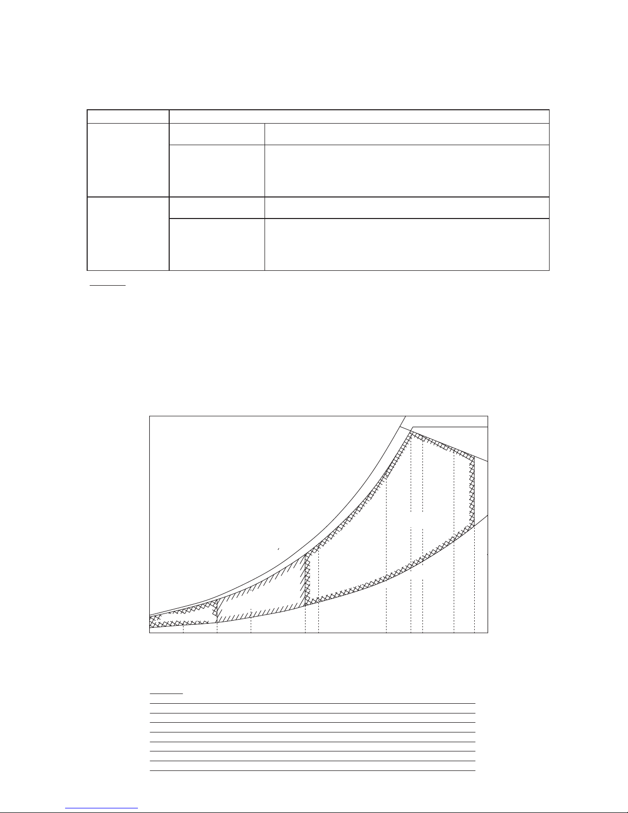
< Heating Mode Operation Range >
23
(-5
)
32
(0)
50
(10)
(*1) (*2)68
(20)
86
(30)
104
(40)
109
(43)
92
(33.5)95(35)
89 (32)
Air Inlet Wet Bulb Temperature
(Outdoor Temperature) (
o
F (
o
C) WB)
Air Inlet Dry Bulb Temperature
(Outdoor Temperature) (
o
F (oC) DB)
75
(24)
41
(5)
Normal Heating
Outdoor Air
Heating
Relative Humidity : 30%RH
Relative Humidity : 90%RH
NOTES:
by the unit's outdoor thermistor.
5. Air inlet dry bulb temperature (outdoor temperature) indicates the temperature detected
the outdoor temperature is low.
6. Make sure to apply extra insulation on the unit and duct to prevent condensation when
1. Make sure the air inlet wet bulb temperature (outdoor temperature) is below 59
o
F WB (15oC WB).
4. Compressor is stopped during outdoor air heating.
3. Unit may not operate when the outdoor temperature is high for All Fresh mode. (*2)
(optional function d7) or prohibits OA intake for All Fresh mode below 41
o
F (5oC). (*1)
2. Outdoor air damper of this unit may remain opened at “Damper Minimum Opening” setting
 Loading...