

Page 1

ENGINEERING MANUAL
INVERTER-DRIVEN MULTI-SPLIT SYSTEM
HEAT PUMP AIR CONDITIONERS
Engineering Manual
TC-16004
Technical Catalog for Outdoor Unit
< Indoor Units >
●Ducted Medium Static (EconoFresh) Type
(H,Y,C)IDM030B21E
(H,Y,C)IDM036B21E
(H,Y,C)IDM048B21E
with EF-456NE
Page 2

Page 3
TC-16004-rev.2
i
IMPORTANT NOTICE AND SAFETY SUMMARY
1. Introduction
2. Important Safety Instructions
This manual should be considered as a permanent part of the air conditioning equipment and should
remain with the air conditioning equipment.
(Transportation/Installation Work) > (Refrigerant Piping Work) > (Electrical Wiring Work) > (Ref. Charge Work) > (Test
Run) > (User)
This Engineering Manual concentrates on heat pump air conditioning units. Read this manual carefully
before performing installations or operations.
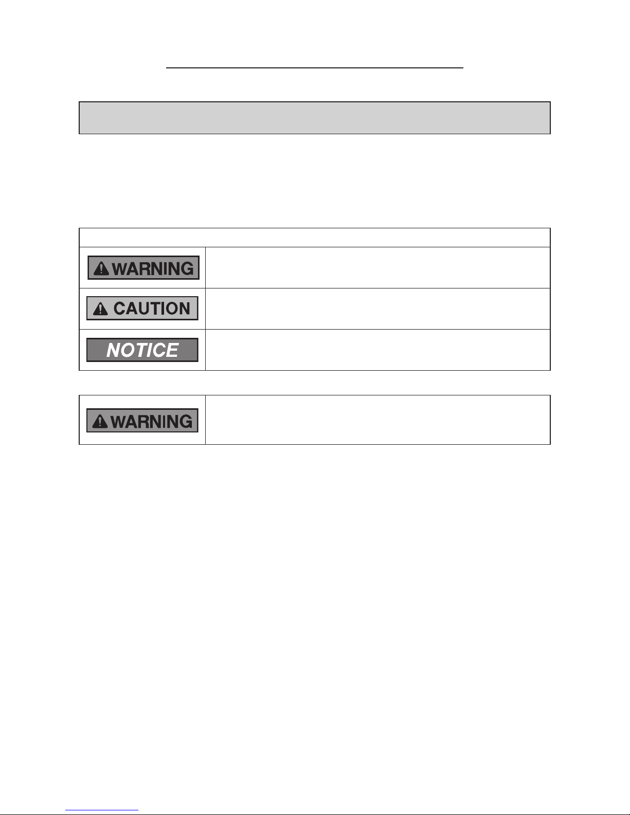
Signal Words
Indicates a hazardous situation that, if not avoided, could result in death or
serious injury.
Indicates a hazardous situation that, if not avoided, could result in minor or
moderate injury.
Indicates information considered important, but not hazard-related
(for example, messages relating to property damage).
General Precautions
To reduce the risk of serious injury or death, read these instructions
thoroughly and follow all warnings or cautions included in all manuals that
accompanied the product and are attached to the unit. Refer back to these
instructions as needed.
● This system should be installed by personnel certied by Johnson Controls, Inc. Personnel must be
qualied according to local, state and national building and safety codes and regulations. Incorrect
installation could cause leaks, electric shock, re or explosion. In areas where Seismic ‘’Performance
requirements are specied, the appropriate measures should be taken during installation to guard
against possible damage or injury that might occur in an earthquake if the unit is not installed
correctly, injuries may occur due to a falling unit.
● Use appropriate Personal Protective Equipment (PPE), such as gloves and protective goggles and,
where appropriate, have a gas mask nearby. Also use electrical protection equipment and tools
suited for electrical operation purposes. Keep a quenching cloth and a re extinguisher nearby during
brazing. Use care in handling, rigging, and setting of bulky equipment.
● When transporting, be careful when picking up, moving and mounting these units. Although the
unit may be packed using plastic straps, do not use them for transporting the unit from one location
to another. Do not stand on or put any material on the unit. Get a partner to help, and bend with
your knees when lifting to reduce strain on your back. Sharp edges or thin aluminum ns on the air
conditioner can cut ngers, so wear protective gloves.
● Do not touch or adjust any safety devices inside the indoor or outdoor units. All safety features,
disengagement, and interlocks must be in place and functioning correctly before the equipment is
put into operation. If these devices are improperly adjusted or tampered with in any way, a serious
accident can occur. Never bypass or jump-out any safety device or switch.
● Johnson Controls will not assume any liability for injuries or damage caused by not following steps
outlined or described in this manual. Unauthorized modications to Johnson Controls products are
prohibited as they…
◦ May create hazards which could result in death, serious injury or equipment damage.
◦ Will void product warranties.
◦ May invalidate product regulatory certications.
◦ May violate OSHA standards.
Page 4

ii
TC-16004-rev.2
Take the following precautions to reduce the risk of property damage.
● Be careful that moisture, dust, or variant refrigerant compounds not enter the refrigerant cycle during
installation work. Foreign matter could damage internal components or cause blockages.
● If air lters are required on this unit, do not operate the unit without the air lter set in place. If the air
lter is not installed, dust may accumulate and breakdown may result.
● Do not install this unit in any place where silicon gases can coalesce. If the silicon gas molecules
attach themselves to the surface of the heat exchanger, the nned surfaces will repel water. As a
result, any amount of drainage moisture condensate can overow from the drain condensate pan and
could run inside of the electrical box, possibly causing electrical failures.
● When installing the unit in a hospital or other facility where electromagnetic waves are generated
from nearby medical and/or electronic devices, be prepared for noise and electronic interference
Electromagnetic Interference (EMI). Do not install where the waves can directly radiate into the
electrical box, controller cable, or controller. Inverters, appliances, high-frequency medical equipment,
and radio communications equipment may cause the unit to malfunction. The operation of the unit
may also adversely affect these same devices. Install the unit at least 10 ft. (approximately 3m) away
from such devices.
● When a wireless controller is used, locate at a distance of at least 3.3 ft. (approximately 1m) between
the indoor unit and electric lighting. If not, the receiver part of the unit may have difculty receiving
operation commands.
● Do not install the unit in any location where animals and plants can come into direct contact with the
outlet air stream. Exposure could adversely affect the animals and plants.
● Do not install the unit with any downward slope to the side of the drain boss. If you do, you may have
drain water owing back which may cause leaks.
● Be sure the drain hose discharges water properly. If connected incorrectly, it may cause leaks.
● Do not install the unit in any place where oil can seep onto the units, such as table or seating areas in
restaurants, and so forth. For these locations or social venues, use specialized units with oil-resistant
features built into them. In addition, use a specialized ceiling fan designed for restaurant use. These
specialized oil-resistant units can be ordered for such applications. However, in places where large
quantities of oil can splash onto the unit, such as a factory, even the specialized units cannot be used.
These products should not be installed in such locations.
● If the wired controller is installed in a location where electromagnetic radiation is generated, make
sure that the wired controller is shielded and cables are sleeved inside conduit tubing.
● If there is a source of electrical interference near the power source, install noise suppression
equipment (lter).
● During the test run, check the unit’s operation temperature. If the unit is used in an environment
where the temperature exceeds the operation boundary, it may cause severe damage. Check the
operational temperature boundary in the manual. If there is no specied temperature, use the unit
within the operational temperature boundary of 35 to 104°F (0 to 40°C).
● Read installation and appropriate user manuals for connection with PC or peripheral devices. If a
warning window appears on the PC, the product stops, does not work properly or works intermittently,
immediately stop using the equipment.
Page 5

TC-16004-rev.2
iii
Installation Precautions
To reduce the risk of serious injury or death, the following installation
precautions must be followed.
● When installing the unit into…
◦ A wall: Make sure the wall is strong enough to hold the unit’s weight. It may be necessary to
construct a strong wood or metal frame to provide added support.
◦ A room: Properly insulate any refrigerant tubing run inside a room to prevent “sweating” that can
cause dripping and water damage to wall and oors.
◦ Damp or uneven areas: Use a raised concrete pad or concrete blocks to provide a solid, level
foundation for the unit to prevent water damage and abnormal vibration.
◦ An area with high winds: Securely anchor the outdoor unit down with bolts and a metal frame.
Provide a suitable air bafe.
◦ A snowy area (only for Heat Pump Model): Install the outdoor unit on a raised platform that is
higher than drifting snow. Provide snow vents.
● If the remote sensors are not used with this controller, then do not install this controller…
◦ in a room where there is no thermostat.
◦ where the unit is exposed to direct sunshine or direct light.
◦ where the unit will be in close proximity to a heat source.
◦ where hot/cold air from the outdoors, or a draft from elsewhere (such as air vents, diffusers or
grilles) can affect air circulation.
◦ in areas with poor air circulation and ventilation.
● Do not install the unit in the following places. Doing so can result in an explosion, re, deformation,
corrosion, or product failure.
◦ Explosive or ammable atmosphere.
◦ Where re, oil, steam, or powder can directly enter the unit, such as in close proximity or directly
above a kitchen stove.
◦ Where oil (including machinery oil) may be present.
◦ Where corrosive gases such as chlorine, bromine, or sulde can accumulate, such as near a hot
tub or hot spring.
◦ Where dense, salt-laden airow is heavy, such as in coastal regions.
◦ Where the air quality is of high acidity.
◦ Where harmful gases can be generated from decomposition.
● Do not position the drain pipe for the indoor unit near any sanitary sewers where corrosive gases
may be present. If you do, toxic gases can seep into breathable air spaces and can cause respiratory
injuries. If the drainpipe is installed incorrectly, water leakage and damage to the ceiling, oor,
furniture, or other possessions may result. If condensate piping becomes clogged, moisture can back
up and can drip from the indoor unit. Do not install the indoor unit where such dripping can cause
moisture damage or uneven locations: Use a raised concrete pad or concrete blocks to provide a
solid, level foundation for the unit to prevent water damage and abnormal vibration.
● Before performing any brazing work, be sure that there are no ammable materials or open ames
nearby.
● Perform a test run to ensure normal operation. Safety guards, shields, barriers, covers, and protective
devices must be in place while the compressor/unit is operating. During the test run, keep ngers and
clothing away from any moving parts.
● Clean up the site when nished, remembering to check that no metal scraps or bits of wiring have
been left inside the unit being installed.
● During transportation, do not allow the backrest of the forklift make contact with the unit, otherwise,
it may cause damage to the heat exchanger and also may cause injury when stopped or started
suddenly.
● Remove gas inside the closing pipe when the brazing work is performed. If the brazing ller metal is
melted with remaining gas inside, the pipes will be blown off and it may cause injury.
● Be sure to use nitrogen gas for an airtight test. If other gases such as oxygen gas, acetylene gas or
uorocarbon gas are accidentally used, it may cause explosion or gas intoxication.
After installation work for the system has been completed, explain the “Safety Precautions,” the proper use
and maintenance of the unit to the customer according to the information in all manuals that came with the
system. All manuals and warranty information must be given to the user or left near the Indoor Unit.
Page 6

iv
TC-16004-rev.2
Refrigerant Precautions
To reduce the risk of serious injury or death, the following refrigerant
precautions must be followed.
● As originally manufactured, this unit contains refrigerant installed by Johnson Controls. Johnson
Controls uses only refrigerants that have been approved for use in the unit’s intended home country
or market. Johnson Controls distributors similarly are only authorized to provide refrigerants that
have been approved for use in the countries or markets they serve. The refrigerant used in this unit
is identied on the unit’s faceplate and/or in the associated manuals. Any additions of refrigerant into
this unit must comply with the country’s requirements with regard to refrigerant use and should be
obtained from Johnson Controls distributors. Use of any non-approved refrigerant substitutes will void
the warranty and will increase the potential risk of injury or death.
● If installed in a small room, take measures to prevent the refrigerant from exceeding the maximum
allowable concentration in the event that refrigerant gases should escape. Refrigerant gases can
cause asphyxiation (0.026 lbs/ft
3
(0.42 kg/m3) based on ISO 5149 for R410A). Consult with your
distributor for countermeasures (ventilation system and so on). If refrigerant gas has leaked during the
installation work, ventilate the room immediately.
● Check the design pressure for this product is 601 psi (4.15MPa). The pressure of the refrigerant
R410A is 1.4 times higher than that of the refrigerant R22. Therefore, the refrigerant piping for
R410A shall be thicker than that for R22. Make sure to use the specied refrigerant piping. If not, the
refrigerant piping may rapture due to an excessive refrigerant pressure. Besides, pay attention to
the piping thickness when using copper refrigerant piping. The thickness of copper refrigerant piping
differs depending on its material.
● The refrigerant R410A is adopted. The refrigerant oil tends to be affected by foreign matters such
as moisture, oxide lm, (or fat). Perform the installation work with care to prevent moisture, dust, or
different refrigerant from entering the refrigerant cycle. Foreign matter can be introduced into the cycle
from such parts as expansion valve and the operation may be unavailable.
● To avoid the possibility of different refrigerant or refrigerant oil being introduced into the cycle, the
sizes of the charging connections have been changed from R407C type and R22 type. It is necessary
to prepare the appropriate tools before performing installation work.
● Use refrigerant pipes and joints which are approved for use with R410A.
● A compressor/unit comprises a pressurized system. Never loosen threaded joints while the system is
under pressure and never open pressurized system parts.
● Before installation is complete, make sure that the refrigerant leak test has been performed. If
refrigerant gases escape into the air, turn OFF the main switch, extinguish any open ames and
contact your service contractor. Refrigerant (Fluorocarbon) for this unit is odorless. If the refrigerant
should leak and come into contact with open ames, toxic gas could be generated. Also, because the
uorocarbons are heavier than air, they settle to the oor, which could cause asphyxiation.
● When installing the unit, and connecting refrigerant piping, keep all piping runs as short as
possible, and make sure to securely connect the refrigerant piping before the compressor starts
operating. If the refrigerant piping is not connected and the compressor activates with the stop
valve opened, the refrigerant cycle will become subjected to extremely high pressure, which can
cause an explosion or re.
● Tighten the are nut with a torque wrench in the specied manner. Do not apply excessive force to the
are nut when tightening. If you do, the are nut can crack and refrigerant leakage may occur.
● When maintaining, relocating, and disposing of the unit, dismantle the refrigerant piping after the
compressor stops.
● When pipes are removed out from under the piping cover, after the insulation work is completed,
cover the gap between the piping cover and pipes by a packing (eld-supplied). If the gap is not
covered, the unit may be damaged if snow, rain water or small animals enter the unit.
● Do not apply an excessive force to the spindle valve at the end of opening. Otherwise, the spindle
valve ies out due to refrigerant pressure. At the test run, fully open the gas and liquid valves,
otherwise, these devices will be damaged. (It is closed before shipment.)
● If the arrangement for outdoor units is incorrect, it may cause owback of the refrigerant and result in
failure of the outdoor unit.
● The refrigerant system may be damaged if the slope of the piping connection kit exceeds +15
o
.
Page 7

TC-16004-rev.2
v
Electrical Precautions
Take the following precautions to reduce the risk of electric shock, re or
explosion resulting in serious injury or death.
● Highly dangerous electrical voltages are used in this system. Carefully refer to the wiring diagram
and these instructions when wiring. Improper connections and inadequate grounding can cause
serious injury or death.
● Perform all electrical work in strict accordance with this installation and maintenance manual and all
the relevant regulatory standards.
● Before servicing, open and tag all disconnect switches. Never assume electrical power is
disconnected. Check with meter and equipment.
● Only use electrical protection equipment and tools suited for this installation.
● Insulate a wired controller against moisture and temperature extremes.
● Use specied cables between units.
● The new air conditioner may not function normally in the following instances:
◦ If electrical power for the new air conditioner is supplied from the same transformer as the device*
referred to below.
◦ If the power source cables for this device* and the new air conditioner unit are located in close
proximity to each other.
Device*: (Example): A lift, container crane, rectier for electric railway, inverter power device,
arc furnace, electric furnace, large-sized induction motor and large-sized switch.
Regarding the cases mentioned above, surge voltage may be inducted into the power supply
cables for the packaged air conditioner due to a rapid change in power consumption of the device
and an activation of a switch.
Check eld regulations and standards before performing electrical work in order to protect the
power supply for the new air conditioner unit.
● Communication cabling shall be a minimum of AWG18 (0.82mm
2
), 2-Conductor, Stranded Copper.
Shielded cable must be considered for applications and routing in areas of high EMI and other
sources of potentially excessive electrical noise to reduce the potential for communication errors.
When shielded cabling is applied, proper bonding and termination of the cable shield is required
as per Johnson Controls guidelines. Plenum and riser ratings for communication cables must be
considered per application and local code requirements.
● The polarity of the input terminals is important, so be sure to match the polarity when using contacts
that have polarity.
● Use an exclusive power supply for the air conditioner at the unit’s rated voltage.
● Highly dangerous electrical voltages may be used in this system. Carefully refer to the wiring diagram
and these instructions when wiring. Improper connections and inadequate grounding can cause
serious injury or death.
● Before installing the controller or remote devices, ensure that the indoor and outdoor unit operation
has been stopped. Further, be sure to wait at least ve minutes before turning off the main power
switch to the indoor or outdoor units. Otherwise, water leakage or electrical breakdown may result.
● Do not open the service cover or access panel to the indoor or outdoor units without turning OFF the
main power supply. Before connecting or servicing the controller or cables to indoor or outdoor units,
open and tag all disconnect switches. Never assume electrical power is disconnected. Check with a
meter and equipment.
● This equipment can be installed with a Ground Fault Circuit Breaker (GFCI), which is a recognized
measure for added protection to a properly grounded unit. Install appropriate sized breakers / fuses
/ overcurrent protection switches, and wiring in accordance with local, state and NEC codes and
requirements. The equipment installer is responsible for understanding and abiding by applicable
codes and requirements.
Page 8

vi
TC-16004-rev.2
- CONTENTS -
1. General Information (Features) .................................................................................................................. 1-1
2. Ducted Medium Static (EconoFresh) Type ................................................................................................ 2-1
2.1 Unit Nomenclature ............................................................................................................................. 2-1
2.2 Line-up .............................................................................................................................................. 2-1
2.3 General Data ..................................................................................................................................... 2-2
2.4 Dimensional Data .............................................................................................................................. 2-3
2.5 Structure ............................................................................................................................................ 2-4
2.6 Component Data ............................................................................................................................... 2-5
2.7 Operation Space ............................................................................................................................... 2-6
2.8 Sensible Heat Factor (SHF) .............................................................................................................. 2-6
2.9 Combinations of Outdoor Units and Indoor Units .............................................................................. 2-7
2.10 Damper Minimum Setting (Optional Function d7) ............................................................................. 2-7
2.11 Working Range .................................................................................................................................. 2-8
2.12 Fan Performance ............................................................................................................................... 2-10
2.13 Electrical Data ................................................................................................................................... 2-11
2.14 Sound Data ....................................................................................................................................... 2-12
2.15 Control System .................................................................................................................................. 2-13
2.15.1 Refrigerant System .................................................................................................................. 2-13
2.15.2 Standard Operation Sequence ................................................................................................ 2-14
2.15.3 Safety and Control Device Setting ........................................................................................... 2-17
2.15.4 Wiring Diagram ........................................................................................................................ 2-18
IMPORTANT NOTICE AND SAFETY SUMMARY ......................................................................................... i
1. Introduction ................................................................................................................................................ i
2. Important Safety Instructions ..................................................................................................................... i
Page 9

TC-16004-rev.2
vii
- CONTENTS -
3. Optional Parts ............................................................................................................................................ 3-1
3.1 Line Up .............................................................................................................................................. 3-1
3.2 Optional Air Filter: KW-PP456E ........................................................................................................ 3-2
3.2.1 Procedures .............................................................................................................................. 3-2
3.2.2 Service and Maintenance ........................................................................................................ 3-2
3.3 Infrared (IR) Receiver Kit: CWDIRK01 .............................................................................................. 3-3
3.3.1 Specications ........................................................................................................................... 3-3
3.3.2 Dimensions .............................................................................................................................. 3-3
3.3.3 Applicable Models .................................................................................................................... 3-3
3.3.4 Accessories / Options .............................................................................................................. 3-4
3.3.5 Installation ................................................................................................................................ 3-4
3.3.6 Electrical Wiring ....................................................................................................................... 3-7
3.3.7 Setting DIP Switches on Indoor Unit Side ............................................................................... 3-7
3.3.8 Setting DIP Switch on IR Receiver Kit Side ............................................................................. 3-8
3.3.9 Identifying Indoor Units Installed in a Side-by-Side Operation ................................................ 3-9
3.3.10 Simultaneous Operation .......................................................................................................... 3-10
3.3.11 Test Run by Wireless Controller (CIR01) ................................................................................. 3-12
3.3.12 Alarm Indication ....................................................................................................................... 3-12
3.4 3P Connector Cable: PCC-1A ........................................................................................................... 3-13
3.5 Remote Sensor: THM-R2A ................................................................................................................ 3-13
3.6 Relay and 3 Pin Connector Kit: PSC-5RA ......................................................................................... 3-14
4. Selection Data ............................................................................................................................................ 4-1
4.1 Selection Guide ................................................................................................................................. 4-1
4.2 Capacity Table ................................................................................................................................... 4-1
4.2.1 Cooling Capacity ...................................................................................................................... 4-1
4.2.2 Heating Capacity ..................................................................................................................... 4-2
Page 10

Page 11
FEATURES
TC-16004-rev.2
1-1
VRF Air Conditioners
Johnson Controls proudly introduces new Variable Refrigerant Flow (VRF) air conditioners, a highly-efcient
and reliable air-conditioning system. Recently, increased numbers of buildings are requiring "intelligent"
facilities that include communication networks, ofce automation, and a comfortable environment. In
particular, a comfortable environment is becoming more of a year-around requirement in ofce buildings.
The VRF multi-split system air conditioner meets these requirements. The proven combination of the scroll
compressor and inverter provides the best air conditioning for small and medium ofce buildings.
■ VRF System
Johnson Controls has developed the VRF system with its customers in mind.
This system, which is unique in the world, allows the interconnection of indoor units for all our VRF air
conditioners.
This system provides the consumer with greater exibility for installation, which means that the airconditioning systems will integrate better within complex facility structures.
1. General Information (Features)
● Wide Range Line-up
Indoor Unit Type
Capacity (MBH)
6 8 12 15 18 24 30 36 48
Ducted Medium Static (EconoFresh) (H,Y,C)IDM_B21E
: Available
Table 1.1 Indoor Unit Type List
■ Ducted Medium Static (EconoFresh) Type Models
(H,Y,C)IDM030B21E, (H,Y,C)IDM036B21E and (H,Y,C)IDM048B21E with EF-456NE
● Improvement of Energy-Saving
Air renewal has a downside of increased energy consumption. These models save energy while renewing
room air and reducing levels of CO
2
while also eliminating unpleasant smells, smoke and pollution.
(1) Supplies fresh new air into the room while keeping the correct indoor temperature, and also provides
natural cooling for increased energy saving (reducing energy consumption).
(2) Allows inow of fresh air into the room through the indoor unit, even when the thermostat is switched
off (Thermo-OFF*). Depending on the supply air and outlet air temperatures, this unit works like an
intelligent system, controlling the air ow by modifying the position of the damper.
NOTE:
Thermo-On: The outdoor unit and some indoor units are running.
Thermo-OFF: The outdoor unit and some indoor units stay on, but don’t run.
(3) Effectively increases the installation performance when the outdoor temperature is lower than the
room temperature (in cooling mode), allowing the inlet of fresh air and cooling to the set temperature
without activating the outdoor unit. For example, it can supply up to 100% of fresh air and is able to
provide “natural cooling” through a damper when the outdoor temperature is lower than the set indoor
temperature (in cooling mode), leading to signicant energy savings particularly in spring and autumn.
(4) EconoFresh can operate with CO
2
or enthalpy sensors to control the air quality in the room.
NOTE:
The enthalpy sensor and CO
2
gas sensor cannot be installed together.
The enthalpy sensor and CO2 gas sensor have no effect on the EconoFresh operation when the All
Fresh process is activated.
Page 12
FEATURES
1-2
TC-16004-rev.2
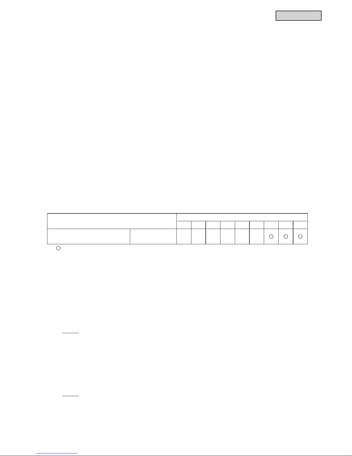
● Damper Control
The EconoFresh kit is equipped with an outdoor air damper control mechanism, and the system provides
various operation modes, such as free cooling, all fresh, in cooling and heating mode.
A micro-computer controls the angle of the damper according to air temperatures to adjust the fresh air
ow, thus keeping the room temperature constant with excellent comfort.
Selectable Minimum Damper Opening
The minimum opening for fresh outdoor air damper is selectable through the wired controller (d7 optional
function setting). This allows establishing a minimum air volume renewal in the room.
Control Box
Suspension Bracket
Return Air Inlet
Damper
Outdoor Air Inlet
Supply Air Outlet
Page 13
FEATURES
TC-16004-rev.2
1-3
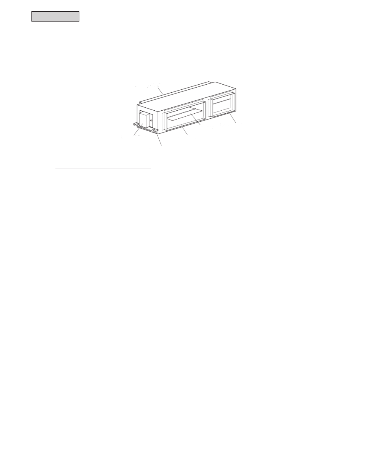
● Standard and All Fresh Process Modes
Two different process modes are selectable:
(1) Standard Process
Standard Process in Cooling Mode
In a situation where the outdoor ambient temperature is lower than 66
o
F (19oC), the compressor stops and
the indoor temperature is cooled down with an intake of outdoor fresh cold air controlled by the damper.
The minimum guaranteed fresh air intake can be set through the d7 setting (7% or more of the total outlet
air).
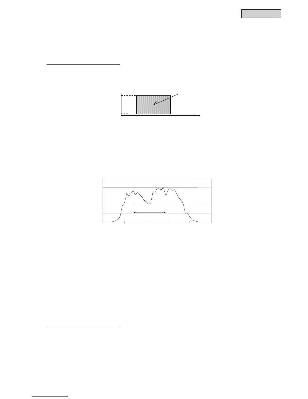
• Cooling Economizer
An energy saving control is adopted which uses fresh cold air from the outdoors for cooling the
intermediate seasons. The compressor is not used during this control, which results in outstanding
energy saving.
• Three Different Economizer Cooling Controls
In order to optimize energy savings, EconoFresh can manage three types of control: normal cooling,
outdoor air cooling or fan cooling. Each type is managed according to the outdoor air temperature.
• Comfort Control
When Thermo OFF is requested, EconoFresh compares temperatures in order to offer a comfortable
environment in the room. EconoFresh control compares the set temperature (set in the wired controller)
and the inlet air temperature in the Indoor Unit, and requests Thermo ON under certain conditions, in
order to achieve the requested room temperature as soon as possible.
Standard Process in Heating Mode
Depending on the temperature of indoor air return, the damper remains either opened for a minimum
guaranteed intake of fresh air, or fully closed for 10 minutes. After this time, the damper is opened for a
minimum guaranteed intake of fresh air intake; this opening can be set through the d7 setting (7% or more
of the total outlet air).
23
(-5)39(4)
66
(19)
109
(43)
o
F
(
o
C)
100%
7%
Outdoor Temperature
Fresh Air
Working Area
14
(-10)
32
(0)
50
(10)
68
(20)
86
(30)
104
(40)
0
50
100
150
200
250
(h/year)
Outdoor Temperature
Time
Example of Temperature Distribution (8:00-21:00)
Compressor not used for Cooling
o
F
(
o
C)
Page 14

FEATURES
1-4
TC-16004-rev.2
(2) All Fresh Process in Cooling and Heating Mode
This operation mode is very useful for buildings with many tenants, or for public buildings.
Basically, the damper is fully opened (100% fresh air) when activated through the wired controller (E1
optional function setting).
The following parameters are controlled by the All Fresh process in an independent fashion:
* Thermo ON/OFF status
* Damper opening
* Fan speed
Thermo ON/OFF Status
The general principle is that the compressor remains stopped when the outdoor ambient temperature is
lower than 63
o
F (17oC) in cooling mode and higher than 75oF (24oC) in heating mode.
Damper Opening
The damper is set to be either fully open or closed to the minimum opening to ensure an intake of fresh air
(7% or more of the total outlet air, by the d7 setting).
Additionally, the damper is closed to the minimum opening to ensure an intake of fresh air, under certain
temperature combinations.
Fan Speed
The fan speed is adjusted one tap lower when the air outlet temperature...
* rises higher than 68oF (20oC) in cooling mode
* drops lower than 86oF (30oC) in heating mode
In the above cases, the fan speed is changed from high to medium, or from medium to low.
The fan speed is adjusted back to fan setting tap when air outlet temperature returns to the following
ranges:
* 59
o
F (15oC) or lower in cooling mode
* 95oF (35oC) or higher in heating mode
Draft Prevention Control
Additionally, while the All Fresh process is activated, the EconoFresh control keeps monitoring and
comparing several temperature parameters. The damper may be closed to the minimum opening to
ensure the intake of fresh air under certain circumstances, and in order to avoid discomfort and unwanted
changes to room temperature due to inlet outdoor air conditions.
This function is active if the outdoor ambient temperature is
* 9
o
F (5oC) higher than the setting temperature in cooling thermo-OFF
* 9oF (5oC) lower than the setting temperature in heating thermo-OFF
100%
7%
39
(4)
o
F
(
o
C)
Outdoor Temperature
Fresh Ai
r
● Easy Installation
Equipped with AC drain pump to force condensates up to 33-7/16 inch (850mm) in height in relation to the
unit. The pump is automatically enabled when the accumulated water level is too high.
< 33-7/16 inch
(850mm)
Page 15
TC-16004-rev.2
2-1
DUCTED MEDIUM STATIC (ECONOFRESH)
2. Ducted Medium Static (EconoFresh) Type
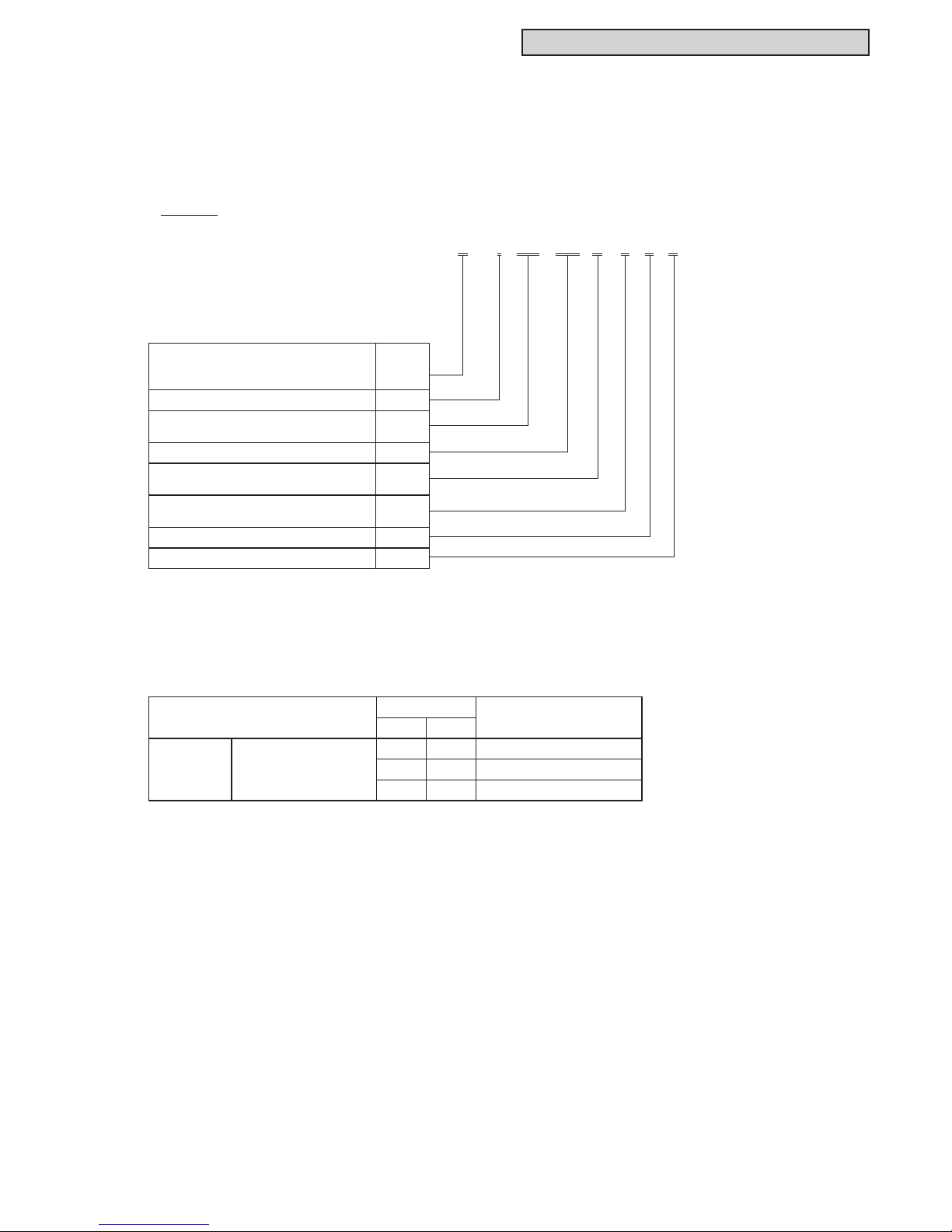
2.1 Unit Nomenclature
Model Descriptions
Example
H I DM 030 B 2 1 E
Nomenclature Description
H = Hitachi Brand
Y = York Brand
C = Coleman Brand
H
Indoor Unit I
Indoor Unit Type
DM = Medium Static
DM
Capacity (MBH) 030
Refrigerant Type
B = R410A
B
Voltage
2 = 208/230Volts - 1Phase - 60Hz
2
1 = 1st Generation 1
E = Economizer Type E
2.2 Line-up
Type
Capacity
Model
RT MBH
Indoor Unit
Ducted Medium Static
(EconoFresh)
2.5 30 (H,Y,C)IDM030B21E
3.0 36 (H,Y,C)IDM036B21E
4.0 48 (H,Y,C)IDM048B21E
Page 16

2-2
TC-16004-rev.2
DUCTED MEDIUM STATIC (ECONOFRESH)
2.3 General Data
NOTES:
*1. Nominal capacity is based on combinations within the VRF system and the following conditions:
Cooling Operation Conditions Heating Operation Conditions
Indoor Air Inlet Temperature: 80°F DB (26.7°C DB) Indoor Air Inlet Temperature: 70°F DB (21.1°C DB)
67°F WB (19.4°C WB) Outdoor Air Inlet Temperature: 47°F DB (8.3°C DB)
Outdoor Air Inlet Temperature: 95°F DB (35.0°C DB) 43°F WB (6.1°C WB)
Piping Length: 24 ft. 7-3/16 in. (7.5m)
Piping Lift: 0 ft. (0m)
*2. The sound pressure level is based on the following conditions.
4.9 ft. (1.5m) beneath the unit, connection with the EconoFresh Kit, EconoFresh Pressure Mode Setting, damper opening
is OA 50% and RA 50%, at rated airow volume and lter is not used.
The above data was measured in an anechoic chamber so that reected sound should be taken into consideration in the
eld.
*3. The data for external pressure is based on a connection with the EconoFresh Kit (with a damper setting of maximum
pressure drop (damper opening at OA 100%)), EconoFresh Pressure Mode Setting and the lter is not used.
Indoor Unit Type
Model (H,Y,C)IDM030B21E (H,Y,C)IDM036B21E (H,Y,C)IDM048B21E
Indoor Unit Power Supply
Nominal Cooling Capacity *1 Btu/h 48,000
(kW) (14.1)
Nominal Heating Capacity *1 Btu/h 54,000
(kW) (15.8)
dB
Outer Dimensions
Height in. (mm) 10-7/8 (275) 10-7/8 (275) 10-7/8 (275)
Width in. (mm) 58-1/16 (1474) 58-1/16 (1474) 58-1/16 (1474)
Depth in. (mm) 23-5/8 (600) 23-5/8 (600) 23-5/8 (600)
Net Weight lbs (kg) 106 (48) 106 (48) 106 (48)
Refrigerant
Indoor Fan
Air Flow Rate *3 cfm
(Hi-Me-Lo)
(m
3
/min)
External Pressure *3
in.W.G
(Hi-Me-Lo) (Pa)
Refrigerant Piping
Liquid Line in. (mm) 3/8 (9.52) 3/8 (9.52) 3/8 (9.52)
Gas Line in. (mm) 5/8 (15.88) 5/8 (15.88) 5/8 (15.88)
Condensate Drain VP25
OD in. (mm) 1-1/4 (32) 1-1/4 (32) 1-1/4 (32)
ID in. (mm) 1 (25) 1 (25) 1 (25)
Adaptable EconoFresh Kit Model
Outer Dimensions
Height in. (mm)
Width in. (mm)
Depth in. (mm)
Net Weight lbs. (kg)
(35-31-28)
40-36-33
1271-1130-1024
(36-32-29)
0.15-0.11-0.09 0.13-0.11-0.09 0.11-0.10-0.08
1059-953-847
R410A
(30-27-24)
Ducted Medium Static (EconoFresh)
Sound Pressure Level *2
(Overall A Scale)
30,000 36,000
(8.8) (10.5)
34,000 40,000
(10.0) (11.7)
AC 1 Phase, 208/230V, 60Hz
38-35-32 39-35-33
1236-1094-988
EF-456NE
VP25 VP25
(37-27-22) (32-28-22) (27-25-20)
(12.5)
10
55-1/2
12-3/16
28
(254)
(1410)
(270)
Page 17

TC-16004-rev.2
2-3
DUCTED MEDIUM STATIC (ECONOFRESH)
2.4 Dimensional Data
Unit: inch (mm)
Models: (H,Y,C)IDM030B21E, (H,Y,C)IDM036B21E and (H,Y,C)IDM048B21E
with EconoFresh Kit EF-456NE
NOTE:
Connect the EconoFresh kit directly to the indoor unit.
Page 18

2-4
TC-16004-rev.2
DUCTED MEDIUM STATIC (ECONOFRESH)
2.5 Structure
Models: (H,Y,C)IDM030B21E, (H,Y,C)IDM036B21E and (H,Y,C)IDM048B21E
with EconoFresh Kit EF-456NE,C
Unit: inch (mm)
Condensate Pan
Electronic Expansion Valve
Condensate Pump
Page 19

TC-16004-rev.2
2-5
DUCTED MEDIUM STATIC (ECONOFRESH)
2.6 Component Data
Indoor Heat Exchanger and Fan
TubMaterial
Outer Diameter φin. (mm) 1/4 (7.0) 1/4 (7.0) 1/4 (7.0)
Rows
Number of Tube/Coil
Fin Material
Pitch in. (mm) 0.071 (1.8) 0.071 (1.8) 0.063 (1.6)
psi (MPa) 601 (4.15) 601 (4.15) 601 (4.15)
ft
2
(
m
2
)
Number/Unit
Outer Diameter φin.
(mm)
Nominal Air Flow cfm
(Hi-Me-Lo)
(
m3/min
)
Starting Method
Nominal Output W
Quantity
Insulation Class
7-1/16
3.20
2
Copper Tube
Model (H,Y,C)IDM030B21E (H,Y,C)IDM036B21E (H,Y,C)IDM048B21E
Multi-Pass Cross Finned TubeHeat Exchanger Type
EEE
111
250 250 250
7-1/16
1059-953-847 1236-1094-988 1271-1130-1024
(180) (180)
(30-27-24) (35-31-28) (36-32-29)
Drip-Proof Type Enclosure
DC Motor
(180)
7-1/16
Aluminum
22
111
Multi-Blade Centrifugal Fan
3.20
Indoor Fan Motor
444
Indoor Fan
Number of Coil/Unit
Maximum Operating Pressure
Total Face Area 3.20
(0.30) (0.30) (0.30)
48 48 48
Page 20

2-6
TC-16004-rev.2
DUCTED MEDIUM STATIC (ECONOFRESH)
2.7 Operation Space
2.8 Sensible Heat Factor (SHF)
Models: (H,Y,C)IDM030B21E, (H,Y,C)IDM036B21E and (H,Y,C)IDM048B21E
with EconoFresh Kit EF-456NE
Model SHF*
(H,Y,C)IDM030B21E 0.83
(H,Y,C)IDM036B21E 0.85
(H,Y,C)IDM048B21E 0.85
NOTE:
SHF is based on combinations within the VRF system and the following conditions:
Cooling Operation Conditions
Indoor Air Inlet Temperature: 80
o
F DB (26.7oC DB)
67oF WB (19.4oC WB)
Outdoor Air Inlet Temperature: 95oF DB (35.0oC DB)
Piping Length: 24 ft. 7-3/16 in. (7.5m)
Piping Lift: 0 ft. (0m)
Rear Side
≥ 15-3/4
(400)
≥ 39-3/8
(1000)
View from Top
Front Side
(5-1/8 (130))
≥ 23-5/8
(600)
≥ 23-5/8
(600)
Electrical Box
Unit: inch (mm)
Service Access Door
(≥ □17-11/16 (450))
If the ceiling board
cannot be found
for servicing,
prepare a service
access door
below the indoor
unit for removing
the indoor unit.
Page 21

TC-16004-rev.2
2-7
DUCTED MEDIUM STATIC (ECONOFRESH)
NOTES:
● If the Damper Minimum Setting (optional function d7) of this indoor unit is set to a higher step, then this
will affect the air outlet temperature of other standard indoor units.
● Airow volume must be at the lower limit for All Fresh operation.
● Make sure to enable the EconoFresh Pressure Mode (optional function C5) on the wired controller
before operation. Otherwise, this unit will not operate effectively.
EconoFresh Pressure Mode is “01”. (Optional function C5 on the wired controller is set to “00” by
default)
2.9 Combinations of Outdoor Units and Indoor Units
Indoor units can be connected with the outdoor unit (VRF system).
2.10 Damper Minimum Setting (Optional Function d7)
Relationship between damper minimum opening (optional function d7) and OA airow volume ratio should
be referred to below table.
However, OA airow volume ratio will change by duct installation.
For example if the OA intake duct is long then the ratio becomes small.
In case precise OA airow volume ratio is required then nd out from outdoor air temperature, indoor
temperature and air outlet temperature during fan mode.
NOTE:
When the opening is bigger, the outdoor air intake increases and this become additional load.
Outdoor Unit Type Combinations of Outdoor Units and Indoor Units
VRF Standard
VRF Less Module
Ducted (EconoFresh)
only
Total capacity of Ducted (EconoFresh) is
70%~100% of the outdoor unit capacity.
Ducted (EconoFresh)
+
Other Standard
Indoor Unit
Total capacity of Ducted (EconoFresh) is
30% or below the outdoor unit capacity.
AND
Total capacity of indoor unit (including Ducted (EconoFresh)) is
70%~100% of the outdoor unit capacity.
VRF Low Ambient
Ducted (EconoFresh)
only
Total capacity of Ducted (EconoFresh) is
55%~80% of the outdoor unit capacity.
Ducted (EconoFresh)
+
Other Standard
Indoor Unit
Total capacity of Ducted (EconoFresh) is
20% or below the outdoor unit capacity.
AND
Total capacity of indoor unit (including Ducted (EconoFresh)) is
55%~80% of the outdoor unit capacity.
Mini VRF
Ducted (EconoFresh)
only
Single Ducted (EconoFresh) only
AND
Total capacity of Ducted (EconoFresh) is
within 100% of the outdoor unit capacity.
Wired Controller Set Description
C5 01 EconoFresh Pressure Mode
C5 00 Not Available (Factory Setting)
C5 02 Not Available
Relationship between Optional Function d7 and OA Airow Volume Ratio
d7 Setting Conditions OA Airow Volume Ratio OA Damper Opening (Angle)
00 5% 6°
01 9% 12°
02 13% 18°
03 17% 24°
04 21% 30°
05 25% 36°
06 29% 42°
07 34% 48°
Page 22

2-8
TC-16004-rev.2
DUCTED MEDIUM STATIC (ECONOFRESH)
< Heating Mode Operation Range >
23
(-5)
32
(0)
50
(10)
(*1) (*2)68
(20)
86
(30)
104
(40)
109
(43)
92
(33.5)95(35)
89 (32)
Air Inlet Wet Bulb Temperature
(Outdoor Temperature) (
o
F (
o
C) WB)
Air Inlet Dry Bulb Temperature
(Outdoor Temperature) (
o
F (oC) DB)
75
(24)
41
(5)
Normal Heating
Outdoor Air
Heating
Relative Humidity : 30%RH
Relative Humidity : 90%RH
NOTES:
1. Make sure to apply extra insulation on the unit and duct to prevent condensation when the outdoor temperature is low.
2. Make sure the air inlet wet bulb temperature (outdoor temperature) is below 59
o
F WB (15oC WB).
3. Outdoor air damper of this unit may remain opened at “Damper Minimum Opening” setting (optional function d7) or
prohibits OA intake for All Fresh mode below 41oF (5oC). (*1)
4. Unit may not operate when the outdoor temperature is high for All Fresh mode. (*2)
5. Compressor is stopped during outdoor air heating.
6. Air inlet dry bulb temperature (outdoor temperature) indicates the temperature detected by the unit's outdoor thermistor
.
2.11 Working Range
This heat pump air conditioner has been designed for the following temperatures. Operate the heat pump
air conditioner within this range.
< Cooling Mode Operation Range >
23
(-5)
32
(0)
50
(10)
(*1) (*2)68
(20)
86
(30)
104
(40)
109
(43)
92
(33.5)95(35)
89 (32)
64
(18)
Air Inlet Wet Bulb Temperature
(Outdoor Temperature) (
o
F (
o
C) WB)
Air Inlet Dry Bulb Temperature
(Outdoor Temperature) (
o
F (oC) DB)
41
(5)
Relative Humidity : 90%RH
Relative Humidity : 30%RH
Normal Cooling
Outdoor Air
Cooling
Normal Cooling
NOTES:
1. Make sure to apply extra insulation on the unit and duct to prevent condensation when the outdoor temperature is low.
2. Outdoor air damper of this unit may remain opened at “Damper Minimum Opening” setting (optional function d7) or
prohibits OA intake for All Fresh mode below 41
o
F (5oC). (*1)
3. Unit may not operate when the outdoor temperature is high for All Fresh mode. (*2)
4. Compressor is stopped during outdoor air cooling.
5. Air inlet dry bulb temperature (outdoor temperature) indicates the temperature detected by the unit's outdoor thermistor.
Page 23

TC-16004-rev.2
2-9
DUCTED MEDIUM STATIC (ECONOFRESH)
< Operation Sequence >
14
(-10)
32
(0)
50
(10)
64
(18)
23
(-5)
41
(5)
75
(24)
109
(43)
86
(30)
104
(40)
68
(20)
step1 (*)
ON OFFON
step15 (**)
ON OFFON
step1step controlstep1
ON/OFF
ON OFF
step1step15
ON
step1
step15
step1
Backup Compressor
Cooling
Mode
Compressor
All-Fresh
Compressor
Damper
Heating
Mode
All-Fresh
All-Fresh
All-Fresh
Standard
Economizer
Standard
Economizer
Standard
Economizer
Damper
Fan
Mode
Dry
Mode
Damper
Damper
Compressor
Compressor
ON
step1
Standard
Economizer
Damper
Compressor
Outdoor Temperature
o
F (ºC)
(*) Damper Step 1: Fresh Outdoor Air Damper Minimum Opened
(**) Damper Step 15: Fresh Outdoor Air Damper Fully Opened
Compressor operation and the angle (step) of the damper are controlled according to both room air
temperature and outdoor temperature to adjust the fresh air ow, thus keeping the room temperature
constant.
Page 24

2-10
TC-16004-rev.2
DUCTED MEDIUM STATIC (ECONOFRESH)
2.12 Fan Performance
NOTE:
Field-supplied duct should be installed so that it does not exceed the upper limit of airow volume. When the
internal pressure drop of the duct is limited, the airow volume is higher.
This will cause abnormal stoppage, malfunction, and water splash.
Therefore, ensure that the internal pressure drop of the duct is equal to external static pressure by adjusting the
damper.
Above gure shows when the EconoFresh Pressure Mode is selected on the wired controller.
It is recommended to use at lower limit of airow volume during the All Fresh mode.
(H,Y,C) IDM030B21E
with EF-456NE
(H,Y,C) IDM036B21E
with EF-456NE
(H,Y,C) IDM048B21E
with EF-456NE
Page 25

TC-16004-rev.2
2-11
DUCTED MEDIUM STATIC (ECONOFRESH)
2.13 Electrical Data
VOL: Rated Unit Power Supply Voltage (V)
PH: Phase
HZ: Frequency (Hz)
MCA: Maximum Circuit Ampacity (A)
MFA: Maximum Fuse Ampacity (A)
OPT: Rated Motor Output (kW)
FLA: Full Load Ampacity (A)
Model
Unit Main Power Applicable Voltage Power Supply
Indoor
Fan Motor
Unit
VOL PH HZ Maximum Minimum MCA MFA OPT FLA
(H,Y,C)IDM030B21E
208/230 1 60 253 188
1.7 15 0.25 1.3
(H,Y,C)IDM036B21E 2.2 15 0.25 1.7
(H,Y,C)IDM048B21E 2.3 15 0.25 1.8
NOTE:
Power supply voltage should be satised with the following.
Supply Voltage: Rated Voltage within ±10%
Starting Voltage: Rated Voltage within -15%
Operating Voltage: Rated Voltage within ±10%
Page 26

2-12
TC-16004-rev.2
DUCTED MEDIUM STATIC (ECONOFRESH)
2.14 Sound Data
NOTES:
1. The sound pressure level is based on the following:
Measurement Point: 4.9 ft. (1.5m) beneath the unit.
2. The above data was measured in an anechoic chamber so that reected sound should be taken into consideration in the eld.
3. Above gure shows when the EconoFresh Pressure Mode is selected on the wired controller, damper opening is OA 50% and
RA 50% and at rated airow volume.
(H,Y,C)
(H,Y,C)
Model: (H,Y,C) IDM048B21E
with EF-456NE
Model: (H,Y,C) IDM030B21E
with EF-456NE
Model: (H,Y,C) IDM036B21E
with EF-456NE
Page 27

TC-16004-rev.2
2-13
DUCTED MEDIUM STATIC (ECONOFRESH)
2.15 Control System
2.15.1 Refrigerant System
Mark Part Name
1
Heat Exchanger
2
Distributor
3
Strainer
4
Electronic Expansion Valve
Models: (H,Y,C)IDM030B21E, (H,Y,C)IDM036B21E and (H,Y,C)IDM048B21E
Unit: inch (mm)
Model Distributor
(A) Gas Pipe
Connection
(B) Liquid Pipe
Connection
(C) (OD×T) (D) (OD×T)
(H,Y,C)IDM030B21E 10 Pass
f
5/8
(15.88)
f
3/8
(9.52)
f
3/4×t0.047
(19.05×1.2)
f
1/2×t0.031
(12.7×0.8)
(H,Y,C)IDM036B21E 10 Pass
f
5/8
(15.88)
f
3/8
(9.52)
f
3/4×t0.047
(19.05×1.2)
f
1/2×t0.031
(12.7×0.8)
(H,Y,C)IDM048B21E 10 Pass
f
5/8
(15.88)
f
3/8
(9.52)
f
3/4×t0.047
(19.05×1.2)
f
1/2×t0.031
(12.7×0.8)
Design
Pressure
601 PSIG
(4.15 MPa)
Page 28

2-14
TC-16004-rev.2
DUCTED MEDIUM STATIC (ECONOFRESH)
2.15.2 Standard Operation Sequence
I.U.: Indoor Unit
Auto Cooling/Heating
Operation
I.U. Air
Intake
Temp.
I.U. Air
Intake
Temp.
< Set Temp.
< Set Temp.
> Set
Temp.
> Set Temp.
> Set Temp.
> Set Temp. +1
o
F
(0.5oC)
> Set Temp. +3
o
F (2oC)< Set Temp. -3oF (2oC)
< Set Temp. -1oF
(0.5oC)
Heating
Mode
Cooling
Mode
I.U. Air
Intake
Temp.
Fan
Mode
Fan
Mode
I.U. Air
Intake
Temp.
I.U. Air
Intake
Temp.
< Set Temp.
NOTE:
I.U fan operates continuously when in Cooling, Heating and Fan Mode.
■ Cooling Operation
The sequence may be different depending on the outdoor unit model to be connected. Refer to the “Outdoor
Unit Engineering Manual” for details.
■ Dry Operation
The sequence may be different depending on the outdoor unit model to be connected. Refer to the “Outdoor
Unit Engineering Manual” for details.
■ Heating Operation
The sequence may be different depending on the outdoor unit model to be connected. Refer to the “Outdoor
Unit Engineering Manual” for details.
■ Automatic Cooling and Heating Operation
It is applicable only for the Heat Recovery System.
■ Defrosting Operation
The sequence may be different depending on the outdoor unit model to be connected. Refer to the “Outdoor
Unit Engineering Manual” for details.
Page 29

TC-16004-rev.2
2-15
DUCTED MEDIUM STATIC (ECONOFRESH)
Power Supply
No
Yes
No
No
Yes
Yes
Cooling Operation
Cooling Operation
> 32
o
F(0oC)
< 32oF(0oC)
> 58
o
F(14oC)
< 58oF(14oC)
Gas or Liquid Pipe
Surface Temp. of
Indoor Heat Exchanger
Is it continuous for
more than 3 min.?
Is it continuous
for more than 3 min.?
(6 min. in case of
Dry Operation)
Is compressor
operated for more than
15 min.?
*
* The check interval differs
depending on the conditions.
I.U. Electronic Expansion Valve:
Completely Closed
No
No
Yes
MIF Operation at Set Fan Speed
(In case of Dry Operation,
MIF Operation: OFF for 6 min.)
Gas or Liquid Pipe
Surface Temp. of
Indoor Heat Exchanger
Yes
Elapsed Time:
15 min.
Either of Pipe Surface
Temp.
*2)
> 36oF(2oC)
I.U.: Indoor Unit
a
a
*2): Pipe Surface Temp.
NOT adopted at .
MIF : Motor for Indoor Fan
■ Freeze Protection Control during Cooling or Dry Operation
Page 30

2-16
TC-16004-rev.2
DUCTED MEDIUM STATIC (ECONOFRESH)
> 149oF(65oC)
< 149oF(65oC)
Thermo-ON/OFF Control for Indoor Unit
I.U.: Indoor Unit
Heating Operation
I.U. Air
Outlet
Temp.
Thermo-OFF
Yes
No
< 149
o
F(65oC)
> 149
o
F(65oC)
No
Yes
I.U. Air
Outlet
Temp.
Elapsed Time:
3 min.
Thermo-ON
Set Temp. is
lower than
Air Intake Temp.
■ Prevention Control for Excessively High Outlet Air Temperature
(High Outlet Air Temperature Heat Lockout)
NOTE:
Thermo-ON: The outdoor unit and some indoor units are running.
Thermo-OFF: The outdoor unit and some indoor units stay on, but don't run.
Page 31

TC-16004-rev.2
2-17
DUCTED MEDIUM STATIC (ECONOFRESH)
2.15.3 Safety and Control Device Setting
Model (H,Y,C)IDM030B21E, (H,Y,C)IDM036B21E, (H,Y,C)IDM048B21E
For Evaporator Fan Motor
Internal Thermostat Automatic Reset, Non-Adjustable
Cut-Out
o
F
(
o
C)
248+13
(120+7)
Cut-In
o
F
(
o
C)
230+13
(110+7)
For Control Circuit
Fuse Capacity A 5
Page 32

2-18
TC-16004-rev.2
DUCTED MEDIUM STATIC (ECONOFRESH)
2.15.4 Wiring Diagram
Ground
DIP
DIP
DIP
DIP
DIP
DIP
Electronic Expansion Valve
Page 33

TC-16004-rev.2
3-1
OPTIONAL PART
Item No. Optional Parts
Optional Parts
Model Name
3.2 Optional Air Filter KW-PP456E
3.3 Infrared (IR) Receiver Kit CWDIRK01
3.4 3P Connector Cable PCC-1A
3.5 Remote Sensor THM-R2A
3.6 Relay and 3 Pin Connector Kit PSC-5RA
3.7 Wired Controller CIW01
3.8 Simplied Wired Controller CIS01
3.9 Wireless Controller CIR01
3.10 Mini Central Controller CCM01
3.11 Large Central Controller CCL01
3.12 Computerized Central Controller Software / Adapter CCCS01 / CCCA01
Refer to the Engineering Manual of Control for details of item 3.7 to 3.12.
3. Optional Parts
3.1 Line Up
Page 34

3-2
TC-16004-rev.2
OPTIONAL PART
3.2 Optional Air Filter: KW-PP456E
KW-PP456E is only available to be used in combination with the indoor unit ducted medium static
(EconoFresh) type models.
3.2.1 Procedures
(1) Remove the support piece (three screws) from the indoor unit.
(2) Insert the Optional Air Filter and reattach the support piece.
NOTE:
1. During the installation or removal of the optional air lter if the insulation
material attached on the cabinet is removed, then reapply and repair the
insulation. Otherwise, condensation may occur when cold air enters.
2. It is recommended to follow below indications depending on the installation.
- Attach the Optional Air Filter in a situation where no Suction Duct has been applied. (Figure A)
- If applying a Suction Duct, it is recommended that the Air Filter is applied at the inlet point of the Suction
Duct. (Figure B)
Optional Air Filter
EconoFresh Kit
Indoor Unit
Optional Air Filter Support
Optional Air Filter
inserting direction
3.2.2 Service and Maintenance
Remove the Optional Air Filter from the ange. Vacuum dust. Use a cleaner or wash the air lter with
water or neutral detergent to clean the air lter. Dry the air lter away from direct light.
Dimensions:
Unit: inch (mm)
Name Illustration
Optional
Air Filter
50-11/16 (1288)
9-9/16
(243)
1/8 (3)
Optional Air Filter
(Field-Supplied)
Figure
A
Air Filter
(Field-Supplied)
Figure
B
Suction Duct
A
A
Page 35

TC-16004-rev.2
3-3
OPTIONAL PART
To Terminal Block (A, B)
in Electrical Control Box
of Indoor Unit
1-1/8 [28]
IR Receiver Part
4-3/4 [120]
3-9/16 [90]
Accessory Cable
(about 16.4ft [5m])
HEAT
COOL
TIMER
FILTER
DEF
RUN
EMERGENCY
3.3.2 Dimensions
3.3.3 Applicable Models
Model CWDIRK01
Applicable Indoor Unit Model
General-Purpose
(Ducted and Wall Mount Type)
Applicable Wireless Controller CIR01
3.3 Infrared (IR) Receiver Kit: CWDIRK01
This IR receiver kit is installed with the ducted and wall mount types to use with the wireless controller.
3.3.1 Specications
Model CWDIRK01
Outer Dimension
< W × H × D >
3-9/16 × 4-3/4 × 1-1/8 inch
(90 × 120 × 28 mm)
Unit: inch [mm]
Page 36

3-4
TC-16004-rev.2
OPTIONAL PART
3.3.4 Accessories / Options
No. Accessory Qty Remarks
1
IR Receiver Kit
CWDIRK01
1 With Connecting Cable
2
Cable Band 1 For Clamping Cable
3
Securing Screw 4 For Installing IR Receiver Kit
4
Securing Screw 2 For Fixing Cable Clamp
5
Cable Clamp 2 For Clamping Cable
3.3.5 Installation
● Turn OFF the power supply completely before setting the DIP switch, installation work, and electrical
wiring work for the IR receiver kit. If not, it may cause an electric shock.
● Perform securely the installation work referring to this manual. If the installation is not completed
correctly, the IR receiver kit may fall and cause injury.
● Do not install the IR receiver kit where ammable gases may generate or enter. It may cause heat
generation or a re.
● Correctly perform the electrical wiring work. If electrical work is not completed correctly, heat generation
at the connection, a re or an electric shock may occur.
● Make sure that the electrical wires are securely xed so that no external force affects the terminal
connections of the wiring. Not doing so may cause heat generation or a re.
● When the IR receiver kit is installed near ambient lighting, it may not receive a signal from the wireless
controller. Therefore, pay particular attention to the installation position of the IR receiver kit.
● Do not run the connecting cable for the IR receiver kit and the power supply cable (208/230V) in
parallel. It may cause a malfunction of the IR receiver kit.
● To ensure correct performance, read this manual together with the “Installation and Maintenance
Manual” for the indoor unit and the wireless controller. Forward this information to the building owner
and request that they maintain all the equipment manuals.
● CWDIRK01 is for a general-purpose IR receiver kit. It is applied for ducted, cassette, wall mount,
ceiling-suspended, and oor type indoor units.
Page 37

TC-16004-rev.2
3-5
OPTIONAL PART
3
Install the IR receiver kit using the length of
connecting cable (accessory).
The cable length is approximately 17 ft. (5m).
4
Open the cover of the IR receiver kit.
Push the slotted screwdriver with a tip width of
approximately 1/4 inch (6mm) into the slot of the
IR receiver kit cover and rotate it to open the
cover as shown in the gure at the right.
1
Perform the installation work for the IR receiver kit while the indoor unit is being installed.
2
Turn OFF the power supply for the indoor unit if the IR receiver kit is attached after the indoor unit is
installed.
5
Mount the IR receiver kit onto the wall or the ceiling surface as shown below.
Situation A
(1) Secure the bracket.
Situation B
(1) Prepare the eld-supplied switch box (JIS
Box). (JIS C8340)
Slot
IR Receiver Ki
t
Mounting Bracket
Rotate
Push and rotate.
Slotted Screwdriver
(Tip Width:
A
pprox. 1/4 inch (6mm))
Securing Screw
(Accessory)
Secure the bracket with four
accessory securing screws.
Any of the following Switch Boxes
can be utilized.
1. Switch Box for One Switch
(Without Cover)
2. Small Switch Box for One Switch
(Without Cover)
3. Switch Box for One Switch
(With Cover)
Metal Conduit
(larger than I.D. φ13/16 inch (φ20mm)
Two Securing Screws (M4, Field-Supplied)
Page 38

3-6
TC-16004-rev.2
OPTIONAL PART
(2) Run the connecting cable into the metal
conduit.
(3) Lead the connecting cable through the
knock-out hole.
(3) Secure the bracket.
(4) Attach the IR receiver kit.
Do not pinch the cable between the bracket and the IR receiver kit cover when attaching the IR
receiver kit. Attach the IR receiver kit cover following these directions.
(2) Select the connecting cable outlet direction
and cut out one of the knock-out holes on
the cover.
Cover
Connecting
Cable
Mounting Bracket
Cover
Hook the left side
of the cover to the
mounting bracket.
Push the right side
of the cover onto
the bracket.
Click sound is heard
when the cover is
completely hooked
onto the bracket.
Connecting
Cable
The connecting cable should
not be exposed. Lead it through
the metal conduit in the wall.
Connecting Cable
Securing Screw
(M4, Field-Supplied)
Mounting Bracket
Click sound is heard
when the cover is
completely hooked
onto the bracket.
Cover
Hook the left side of
the cover to the mounting
bracket. Push the right
side of the cover onto
the bracket.
Do not loosen the connecting
cable for the IR receiver kit.
Otherwise, it may become
pinched between the two
components causing a
malfunction of the indoor unit.
Select the connecting
cable outlet direction
and cut out of the
knock-out holes ( ).
Secure the tabs of the cover
into the slots on the left side
of the bracket.
Situation A Situation B
Page 39

TC-16004-rev.2
3-7
OPTIONAL PART
The terminal block (TB2) for the controller cable is located as shown in the gure below. Connect the
connecting cable for the IR receiver kit to terminals A and B at TB2. (There is no polarity between terminals
A and B.) The details for wiring methods can be found in the “Installation and Maintenance Manual” for the
indoor unit.
The following wiring method is an example for wall mount indoor units
NOTE:
After running the connecting cable, clamp the extra length of the connecting cable using the accessory cable
band and place it in the electrical box.
Instructions for setting DIP switches for other indoor units can be found in the Installation and Maintenance
Manual for indoor units. The following DIP switch setting is an example for wall mount indoor units.
1
The factory setting of SW2 before shipment is “Wireless”. When using an IR receiver kit (CWDIRK01), set
the SW2 to “Wired”. If not doing so, the operation is not available.
2
Turn OFF the power supply of the indoor and outdoor units completely before setting the DIP switch.
If not turning off the power, the setting becomes invalid.
3
The positions of the DIP switches are shown below.
Open the switch cover. After the DIP switch is set, re-attach the switch cover. The details for setting DIP
switches for an indoor unit can be found in the Installation and Maintenance Manual for indoor units.
TIWM006 - 012B21S TIWM015 - 030B21S
TIWM006 - 012B21S TIWM015 - 030B21S DIP Switch PCB (PCB2)
Insert the connecting
cable from the rear
side of indoor unit.
Switch Cover
PCB
2
Switch Cover
PCB2
DSW5
RSW2
RSW1
DSW6
DSW9 DSW2
SW1
SW2
DSW3
3.3.6 Electrical Wiring
3.3.7 Setting DIP Switches on Indoor Unit Side
A 12
Electrical Box
Cover
Terminal Block for
Power Supply (TB1)
Screw for
Ground Wiring Connection
Connecting Cable
for IR Receiver Kit
Fix the wires with
cable clamp.
Terminal Block for
Controller Cable (TB2)
Terminal Block for Power Supply (TB1)
Screw for
Ground Wiring Connection
Connecting Cable
for IR Receiver Kit
Terminal Block for
Controller Cable (TB2)
AB1
Page 40

3-8
TC-16004-rev.2
OPTIONAL PART
Review the following optional function settings when a function for the IR receiver kit is selected from the
wireless controller or the centralized controller.
● The optional functions “Cooling Lower Limit for Setting Temperature” and “Heating Upper Limit for Setting
Temperature” are not available with the wireless controller.
● The optional function setting “Fixing of Setting Temperature” is not available. When the operation mode is
changed from the wireless controller, the indicated temperature on the wireless controller becomes the set
temperature of the wired controller.
3
The DIP switch (DSW1) is for the optional function selection. If the optional function selection is required,
set the DIP switch as follows.
1
The following switches are on the IR receiver kit.
NOTE:
When the case is closed, pay particular attention to the outlet position for connecting cable.
Turn OFF the power supply completely before setting the DIP switch for an IR receiver kit.
Not doing so may cause an electric shock.
3.3.8 Setting DIP Switch on IR Receiver Kit Side
3412 56
ON
RUN
DEF
FILTER
TIMER
COOL
HEAT
EMERGENCY
“COOL” Button
“HEAT” Button
CoverPCB
Outlet for
Connecting Cable
Case Mounting Bracket
DIP Switch (DSW1)
(Factory Setting)
(1) Remove the mounting
bracket.
(2) Remove two securing
screws to open the case.
2
Emergency Operation Setting
“COOL” and “HEAT” switches are used for emergency operation when the batteries for the wireless
controller are low.
(1) Switch “COOL”: Press “COOL” so that the cooling operation is started.
Press “COOL” again so that the cooling operation is stopped.
(2) Switch “HEAT”: Press “HEAT” so that the heating operation is started.
Press “HEAT” again so that the heating operation is stopped.
NOTE:
During an emergency operation, a yellow light “
” ashes (0.5 second ON/0.5 second OFF).
The temperature setpoint and the fan speed for the cooling/heating operation are the same as before
starting an emergency operation.
Optional Function
DIP Switch Setting (DSW1)
Details
1 2 3 4 5 6
Main/Sub Setting O X X X X X
Change main (OFF setting)/ sub (ON setting) wireless
controller for a two-wireless controller system.
Identifying of
Indoor Unit
X O X X X X
It functions as B Mode (identication of indoor unit) of
the wireless controller when it is “ON”.
Invalidity of
Emergency Operation
X X X O X X The switches for emergency operation are invalid.
O: ON
X: OFF
Page 41

TC-16004-rev.2
3-9
OPTIONAL PART
Turn OFF the power supply completely before setting the DIP switch for the IR receiver kit.
Not doing so can cause an electric shock.
When two indoor units are installed side by side,
the commands from the wireless controller may
be received by both indoor units. The function,
“Identifying of Indoor Units Installed Side by Side”
enables operation of the individual unit correctly
without interfering with the other unit’s operation.
As shown in the gure at the right, the IR receiver
kit of A and B are set side by side. In this instance,
unit B is set as “Identifying Indoor Units Installed
Side by Side”.
Setting of Identifying of Indoor Units Installed Side by Side
1
IR Receiver Kit Setting
Set the Number 2 pin of the IR receiver kit DIP switch (DSW1) at the “Identied” Unit B “ON” side.
2
Wireless Controller
Set the wireless controller according to the Installation and Maintenance Manual for the Wireless
Controller.
Cancellation of Identifying of Indoor Units Installed Side by Side
1
IR Receiver Kit Setting
Set the Number 2 pin of the IR receiver kit DIP switch (DSW1) “OFF” side for cancellation.
2
Wireless Controller
Cancel the wireless controller setting according to the Installation and Maintenance Manual for the
Wireless Controller.
NOTE:
This function setting is required at the receiver side.
It should be set according to the Installation Manual
for indoor units. Contact your distributor for details.
Indoor Unit
A
Indoor Unit
B
"Identified"
IR Receiver Ki
t
"Identified"
Wireless Controller
IR Receiver
Kit A
IR Receiver
Kit B
3.3.9 Identifying Indoor Units Installed in a Side-by-Side Operation
Page 42

3-10
TC-16004-rev.2
OPTIONAL PART
3.3.10 Simultaneous Operation
● Turn OFF the power supply completely before setting the DIP switch and electrical wiring work for the
IR receiver kit. Not doing so can cause an electric shock.
● Accurately perform the electrical wiring work. If the electrical work is not completed correctly, heat
generation at the connection, a re, or an electric shock may occur.
● Make sure that the electrical wires are adequately clamped with a cable clamp and not in a manner that
applies too much external force to the terminal connections of the wirings. If done correctly, the result
could cause heat generation or a re.
● Do not run the connecting cable for IR receiver kit and the power supply cable (208/230V) in parallel.
It may cause a malfunction of the IR receiver kit.
(Example of 4-way cassette type indoor units.)
Up to 16 indoor units can be simultaneously
controlled using one wireless controller.
When multiple indoor units are installed in a large
room, all the indoor units can be controlled to start/
stop with only one wireless controller.
NOTE:
Do not apply a simultaneous operation for the indoor
units installed separately in different rooms.
Some units may be left without turning OFF the
power supply.
Installation of IR Receiver Kit
In an instance of simultaneous operation of multiple (up to 16 ) indoor units by the wireless controller, install
the IR receiver kit only to the unit to be operated. Other units should be the standard units without the IR
receiver kit. If multiple IR receiver kits are required to be installed, two IR receiver kits are the maximum.
Wireless Controller
Indoor Unit
with IR Receiver Kit
Standard
Indoor Unit
Standard Indoor Unit or
Indoor Unit with IR Receiver Kit
Standard
Indoor Unit
Should be Standard Indoor Units
Available to Install IR Receiver Ki
t
Indoor Unit
(Address setting
is required.)
Wireless Controller
Control Cable
between
Indoor Units
Control Example of Simultaneous
Operation of Multiple Units
Page 43

TC-16004-rev.2
3-11
OPTIONAL PART
3
Unit Number Setting
The indoor unit numbers are set by the auto-address function. Therefore, an indoor unit number setting
is not required. If the indoor unit number is xed, set the unit number of all indoor units respectively and
serially. It is recommended that the unit number settings begin with “1”. The setting is set not to overlap
the unit number.
Electrical Wiring Connecting and Setting
1
Connection between Indoor Units
Perform the connection work as shown below.
2
Do not run the connected wireless controller cable and the power supply cable (208/230V) in parallel in
the indoor units.
Stabilize the cable with cable bands. Along with the wiring outside the indoor units, the control cables
should not run with the power supply cable (208/230V). Keep a separation of more than 12 inches (30cm)
or run the cable through a grounded metal conduit.
OFF
ON
Unit Number Setting
DSW6 (Tens Digit) RSW1 (Units Digit)
1 2 3 4 5 6
Set No.1 pin ON.
OFF
ON
1 2 3 4 5 6
DSW6 RSW1
Ex.: Set for No. 16 Unit
Setting
Position
Set by inserting
slotted screwdriver
into the groove.
Set at "6".
Factory setting for DSW6 and RSW1 were set to "0".
Max. 63 units are available for setting.
Indoor Unit No.1 Indoor Unit No.2 Indoor Unit No.3
Connecting Cable
(Accessory)
Wired Controller Cable
Control Cable
(No Polarity)
Power
Supply
Cable
(208/230V)
IR Receiver Kit
For twin, triple or quad combinations,
a communication cable for the wireless
controller is not required.
Use the field-supplied communication cable (AWG18)
for the wired controller cable. The total length
should be within 1640ft (500m). If the total length
is less than 98ft (30m), AWG22 cables can be used.
Power Supply Cable 208/230V
TB
1
TB
2
AB12
L
1
TB
1
L2N
TB
2
AB12
TB
2
AB12
TB
1
L1L2NL
1L2
N
Page 44

3-12
TC-16004-rev.2
OPTIONAL PART
3.3.11 Test Run by Wireless Controller (CIR01)
After all installations are completed, a test run should be performed.
(1) Perform the test run according to the Installation Manual of the wireless controller.
(2) The test run from the wireless controller switch takes two hours to complete.
NOTE:
For the wall mount indoor units, if the TIMER indicator (green) is ashing (0.5 second ON/0.5 second
OFF) after two hours, an alarm may occur. Operate the indoor unit ,and check for abnormality.
3.3.12 Alarm Indication
● If a malfunction occurs, such as safety device actuation, during the test run or the normal
operation, “RUN” (red light) ashes (0.5 second ON / 0.5 second OFF).
● The alarm codes are indicated by the number of LED ashes of “DEF” (green light) and “FILTER” (yellow
light).
The rst LED light is green. The number of times this LED ashes (0.5 second ON and
OFF) will tell you the “DEF” Alarm Code.
The second LED light is yellow. The number of times this LED ashes (0.5 second ON and
OFF) will tell you the “FILTER” Alarm Code.
Example
● ”RUN” (red light) ashing (1 second ON/1 second OFF) indicates an abnormal transmission (connector
loose, connector disconnection, broken wire, or incorrect wiring, or something similar) between the
indoor unit and the IR receiver kit.
● When the IR receiver kit is connected to multiple indoor units, the alarm code is indicated for each
indoor unit in order.
Alarm Code Table
Further details for alarm codes can be found in the “Installation and Maintenance Manual” for the indoor unit.
"FILTER" (yellow light)
Alarm
3 5
"DEF" (green light)
"DEF" flashes three times (0.5 second ON/ 0.5 second OFF)
"FILTER" flashes five times (0.5 second ON/ 0.5 second OFF
)
These signals are repeated until the alarm is reset.
Page 45

TC-16004-rev.2
3-13
OPTIONAL PART
3.4 3P Connector Cable: PCC-1A
This accessory connector is utilized to provide remote start/stop capability (binary input) to an indoor unit and
provide operating status (binary output) of an indoor unit's functions. (System Parts: One set contains ve
3P cords.)
3P Connector Cable
Cord
Sensor
2-φ4.5
1-15/16 (50)
1-1/4 (32)3/8 (9)
1-15/16 (50)
1-1/4 (32)3/8 (9)
9/16 (15)
Case
Base
Lead Wire AWG22 (0.3mm2)
Approximately
11-13/16inch (300mm)
Connector
(“XARP-03V” of NIPPON
A
CCHAKU TANSHI = JST)
If long cord is needed,
connect field supplied
wires [AWG22 (0.3 to 0.5mm
2
)]
with soldering.
Name 3P Connector Cable
Model PCC-1A
Remarks
One set contains ve 3P connector
cables.
Specications
Item Specication
Model THM-R2A
Case
Material ABS Resin
Color Silky White
Base
Material ABS Resin
Color Silky White
Sensor
Part Name Thermistor
Cord Length approx. 26 ft (8m)
3.5 Remote Sensor: THM-R2A
When a remote temperature sensor is installed with an indoor unit, the indoor unit is congurable to use the
temperature at the location of the remote sensor OR the average of the unit's return air temperature and
the temperature at the location of the remote sensor to control that unit. (reference the specic controller
Installation Manual for function conguration details)
Unit: inch (mm)
Page 46

3-14
TC-16004-rev.2
OPTIONAL PART
3.6 Relay and 3 Pin Connector Kit: PSC-5RA
This relay kit provides for basic input/output integration functionality (indoor unit ON/OFF, operating mode,
alarm status) to third party controllers and Building Management Systems (BMS).
(PSC-5RA)
TB1
TB2
0.3mm2 (AWG22)
- 6 conductors
6.6ft (2m)
(Accessory)
Third Party
Controller
or BMS
PCB
Indoor
Unit
Wired
Controlle
r
Connection Cable
(6 conductors)
Max. 229.7ft (70m)
(field-supplied)
Adapter
CN7
CN3*
Item Signal Description Specications
Third Party
Controller
or BMS
Input 1
Input level signal or pulse signal for voltage
from the third party controller or BMS
Voltage: 12VDC, 10mA
Voltage: 24VDC, 10mA
Pulse Range: 500ms or more
Input 2
Third Party
Controller
or BMS
Output 1
Output signal from the wired controller
24VDC
From 10mA to 1A
Output 2
Refer to the Indoor Unit Manual for Input/Output mode setting by the wired controller.
*: Refer to Service Manual for connector numbers.
Max. 4-1/2 (115)
4 (101)
3-3/8 (86)
1-1/4 (31.5)
1-1/2 (38)
5/16
(7.5)
4-15/16 (125)
4-5/16 (110)
9/16
(15)
3-3/4 (95)
1-9/16 (40)
72-13/16 (1850)
5/16
(7.5)
Connecting Cable
for Indoor Unit
Opening for
Controller or BMS (3rd Party) Cable
Fixing Hole:
ɸ1/4 (6)
PCB
5-7/8 (150)
9/16
(15)
5/16
(7.5)
5/16
(7.5)
Name Relay and 3 Pin Connector Kit
Model PSC-5RA
Unit: inch (mm)
Page 47

SELECTION DATA
TC-16004-rev.2
4-1
4. Selection Data
4.1 Selection Guide
Refer to Engineering Manual for the Outdoor Unit.
4.2 Capacity Table
4.2.1 Cooling Capacity
■ Ducted Medium Static (EconoFresh): (H,Y,C)IDM030B21E, (H,Y,C)IDM036B21E
and (H,Y,C)IDM048B21E
TC: Total Capacity
SHC: Sensible Heat Capacity
NOTE:
Above values for (H,Y,C)IDM-B21E series indicates when unit’s air inlet is indoor air only.
Refer to Outdoor Unit Capacity Tables as actual performance data affected by indoor and outdoor unit
combination.
Indoor Air Temp
(
o
F WB)
Outdoor Air
Temp (
o
F DB)
TC
(MBH)
SHC
(MBH)TC(MBH)
SHC
(MBH)TC(MBH)
SHC
(MBH)TC(MBH)
SHC
(MBH)TC(MBH)
SHC
(MBH)TC(MBH)
SHC
(MBH)TC(MBH)
SHC
(MBH)
70
31.0 25.6 31.7 25.9 32.3 26.0 32.6 26.0 33.7 26.4 34.6 26.7 35.4 26.9
80
30.2 25.2 30.7 25.4 31.2 25.5 31.6 25.6 32.6 25.9 33.5 26.2 34.3 26.5
95
28.2 24.2 28.8 24.5 29.4 24.7 30.0 24.9 31.0 25.3 32.0 25.6 32.7 25.8
110
20.2 19.8 19.8 19.5 19.4 19.2 19.0 19.0 19.2 19.2 19.3 19.3 19.4 19.4
114
17.0 17.0 16.8 16.8 16.7 16.7 16.5 16.5 16.6 16.6 16.7 16.7 16.8 16.8
118
13.8 13.8 13.9 13.9 13.9 13.9 13.9 13.9 14.0 14.0 14.0 14.0 14.0 14.0
70
37.2 31.2 38.0 31.6 38.8 31.7 39.1 31.7 40.4 32.3 41.5 32.6 42.5 32.8
80
36.2 30.6 36.8 31.0 37.4 31.1 37.9 31.3 39.1 31.6 40.2 32.0 41.2 32.4
95
33.8 29.6 34.6 29.9 35.3 30.2 36.0 30.5 37.2 30.9 38.4 31.3 39.2 31.5
110
24.2 24.0 23.8 23.7 23.3 23.3 22.8 22.8 23.0 23.0 23.2 23.2 23.3 23.3
114
20.4 20.4 20.2 20.2 20.0 20.0 19.7 19.7 19.9 19.9 20.0 20.0 20.1 20.1
118
16.6 16.6 16.6 16.6 16.7 16.7 16.7 16.7 16.7 16.7 16.8 16.8 16.8 16.8
70
49.6 41.8 50.6 42.2 51.7 42.4 52.1 42.4 53.9 43.1 55.3 43.6 56.6 44.0
80
48.3 41.0 49.0 41.3 49.8 41.5 50.5 41.8 52.2 42.2 53.6 42.8 54.9 43.3
95
45.1 39.5 46.1 39.9 47.0 40.3 48.0 40.7 49.6 41.4 51.2 41.8 52.2 42.1
110
32.3 32.1 31.7 31.7 31.0 31.0 30.4 30.4 30.6 30.6 30.9 30.9 31.1 31.1
114
27.2 27.2 26.9 26.9 26.6 26.6 26.3 26.3 26.5 26.5 26.6 26.6 26.8 26.8
118
22.1 22.1 22.2 22.2 22.2 22.2 22.2 22.2 22.3 22.3 22.4 22.4 22.4 22.4
048
71 73
030
036
Indoor
Unit
Model
61 63 65 67 69
Page 48

SELECTION DATA
4-2
TC-16004-rev.2
4.2.2 Heating Capacity
■ Ducted Medium Static (EconoFresh): (H,Y,C)IDM030B21E, (H,Y,C)IDM036B21E
and (H,Y,C)IDM048B21E
Indoor Air Temp
(
o
F DB)
63 66 68 70 74 77
Outdoor Air
Temp (
o
F WB)
TC
(MBH)
TC
(MBH)
TC
(MBH)
TC
(MBH)
TC
(MBH)
TC
(MBH)
21 26.7 26.7 26.8 26.8 26.5 26.3
25 28.1 28.1 28.1 28.1 27.7 27.4
29 29.4 29.4 29.4 29.4 28.9 28.5
33 30.7 30.7 30.7 30.7 30.1 29.5
37 32.1 32.1 32.0 32.0 31.2 30.6
41 33.4 33.4 33.4 33.3 32.4 31.7
43 34.1 34.0 34.0 34.0 33.0 32.3
47 35.4 35.4 35.3 35.3 34.0 32.3
51 36.8 36.7 36.7 36.3 34.0 32.3
55 38.6 38.1 37.2 36.3 34.0 32.3
59 38.6 38.1 37.2 36.3 34.0 32.3
21 31.4 31.4 31.5 31.5 31.2 30.9
25 33.0 33.0 33.0 33.1 32.6 32.2
29 34.6 34.6 34.6 34.6 34.0 33.5
33 36.2 36.1 36.1 36.1 35.4 34.7
37 37.8 37.7 37.7 37.7 36.7 36.0
41 39.3 39.3 39.2 39.2 38.1 37.3
43 40.1 40.1 40.0 40.0 38.8 38.0
47 41.7 41.6 41.6 41.5 40.0 38.0
51 43.3 43.2 43.1 42.7 40.0 38.0
55 45.4 44.8 43.8 42.7 40.0 38.0
59 45.4 44.8 43.8 42.7 40.0 38.0
21 42.4 42.4 42.5 42.6 42.1 41.7
25 44.6 44.6 44.6 44.6 44.0 43.5
29 46.7 46.7 46.7 46.7 45.8 45.2
33 48.8 48.8 48.8 48.8 47.7 46.9
37 51.0 50.9 50.9 50.9 49.6 48.6
41 53.1 53.0 53.0 53.0 51.5 50.4
43 54.2 54.1 54.0 54.0 52.4 51.2
47 56.3 56.2 56.1 56.1 54.0 51.2
51 58.4 58.3 58.2 57.7 54.0 51.2
55 61.2 60.5 59.1 57.7 54.0 51.2
59 61.2 60.5 59.1 57.7 54.0 51.2
Indoor
Unit
Model
030
036
048
TC: Total Capacity
NOTE:
Above values for (H,Y,C)IDM-B21E series indicates when unit’s air inlet is indoor air only.
Refer to Outdoor Unit Capacity Tables as actual performance data affected by indoor and outdoor unit
combination.
Page 49

Page 50

© 2016 Johnson Controls, Inc.
TC-16004-rev.2
Code No. LIT-12012293
Revised February 2018
 Loading...