

Johnson Controls (H, Y, C)IDM030B21E, C)IDM036B21E, C)IDM048B21E Installation And Maintenance Manual
...Page 1
PMGB0400B-rev.2
Installation
and
Maintenance
Manual
INVERTER-DRIVEN
MULTI-SPLIT SYSTEM
HEAT PUMP
AIR CONDITIONERS
IMPORTANT:
READ AND UNDERSTAND
THIS MANUAL BEFORE
USING THIS HEAT PUMP
AIR CONDITIONER.
KEEP THIS MANUAL FOR
FUTURE REFERENCE.
Type Model
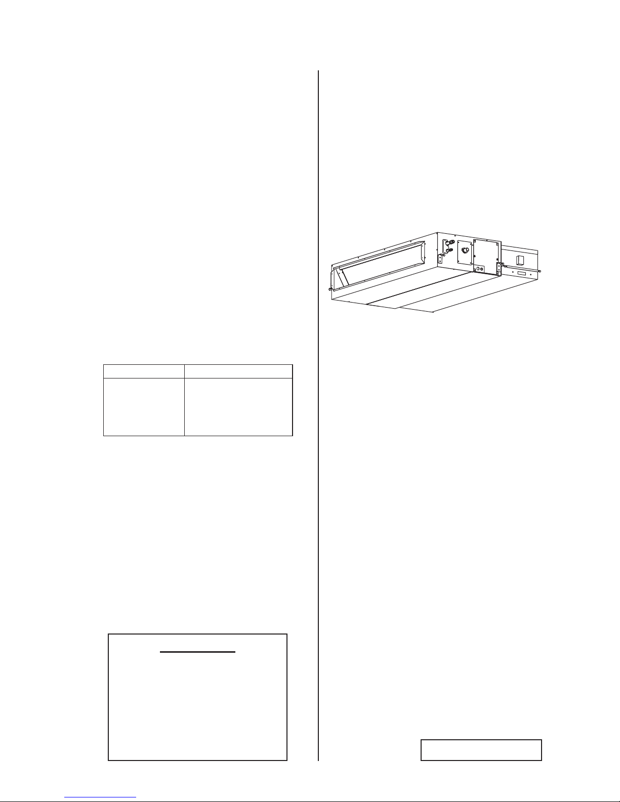
Ducted
(Medium Static)
with
EconoFresh Kit
(H,Y,C)IDM030B21E
(H,Y,C)IDM036B21E
(H,Y,C)IDM048B21E
with
EF-456NE
Page 2

Page 3

PMGB0400B-rev.2
i
Important Notice
● Johnson Controls Inc. pursues a policy of continuing improvement in design and performance in its
products. As such, Johnson Controls Inc. reserves the right to make changes at any time without
prior notice.
● Johnson Controls Inc. cannot anticipate every possible circumstance that might involve a potential hazard.
● This heat pump air conditioning unit is designed for standard air conditioning applications only. Do
not use this unit for anything other than the purposes for which it was intended for.
● The installer and system specialist shall safeguard against leakage in accordance with local
pipetter and electrical codes. The following standards may be applicable, if local regulations are
not available. International Organization for Standardization: (ISO 5149 or European Standard, EN
378). No part of this manual may be reproduced in any way without the expressed written consent of
Johnson Controls Inc.
● This heat pump air conditioning unit will be operated and serviced in the United States of America
and comes with a full complement of the appropriate Safety, Danger, and Caution, Warnings.
● If you have questions, please contact your distributor or dealer.
● This manual provides common descriptions, basic and advanced information to maintain and service
this heat pump air conditioning unit which you operate as well for other models.
● This heat pump air conditioning unit has been designed for a specic temperature range. For optimum
performance and long life, operate this unit within the range limits.
● This manual should be considered as a permanent part of the air conditioning equipment and should
remain with the air conditioning equipment.
Product Inspection upon Arrival
1. Upon receiving this product, inspect it for any damages incurred in transit. Claims for damage, either
apparent or concealed, should be led immediately with the shipping company.
2. Check the model number, electrical characteristics (power supply, voltage, and frequency rating),
and any accessories to determine if they agree with the purchase order.
3. The standard utilization for this unit is explained in these instructions. Use of this equipment for
purposes other than what it designed for is not recommended.
4. Please contact your local agent or contractor as any issues involving installation, performance, or
maintenance arise. Liability does not cover defects originating from unauthorized modications
performed by a customer without the written consent of Johnson Controls, Inc. Performing any
mechanical alterations on this product without the consent of the manufacturer will render your
warranty null and void.
Page 4

ii
PMGB0400B-rev.2
TABLE OF CONTENTS
1. Introduction .....................................................................................................................................................1
2. Safety Instructions ...........................................................................................................................................1
3. Before Installation ...........................................................................................................................................7
3.1 Combination of Outdoor Unit and Indoor Unit ........................................................................................7
3.2 Working Range .......................................................................................................................................7
3.3 Transportation and Handling ..................................................................................................................9
3.4 Factory-Supplied Accessories ................................................................................................................ 9
3.5 Necessary Tools and Instrument List for Installation ..............................................................................9
4. Installation Location ......................................................................................................................................10
5. Installation Work ...........................................................................................................................................11
5.1 Positions of Suspension Bolts and Piping Connections ....................................................................... 11
5.2 Installation of Suspension Bolts ........................................................................................................... 11
5.3 Mounting Indoor Unit ............................................................................................................................12
5.4 Adjusting Level of Unit ..........................................................................................................................13
5.5 Ducting Arrangement ............................................................................................................................13
5.5.1 Pressure Drop of Outdoor Air Duct .............................................................................................13
5.5.2 Pressure Relief Damper ............................................................................................................. 13
5.6 Example of Installation .........................................................................................................................14
5.6.1 Ducting Connection .................................................................................................................... 14
5.6.2 Insulation ....................................................................................................................................14
5.7 Connecting Supply Duct .......................................................................................................................15
5.8 Setting the EconoFresh Pressure Mode ..............................................................................................16
6. Refrigerant Piping Work ................................................................................................................................17
6.1 Piping Materials ....................................................................................................................................17
6.2 Piping Connection Work .......................................................................................................................18
7. Drain Piping ..................................................................................................................................................20
8. Electrical Wiring ............................................................................................................................................22
8.1 General Check .....................................................................................................................................22
8.2 Electrical Wiring Capacity .....................................................................................................................23
8.2.1 Field Minimum Wire Sizes for Power Supply .............................................................................. 23
8.2.2 Details of Electrical Wiring Connection ....................................................................................... 23
8.3 Position of Electrical Wiring Connection ...............................................................................................25
8.4 Wiring Connections ..............................................................................................................................28
8.5 DIP Switch Settings ..............................................................................................................................29
8.6 EconoFresh Pressure Mode Setting ....................................................................................................30
8.7 Function Selection by Wired Controller ................................................................................................31
9. Test Run ........................................................................................................................................................32
9.1 Before Test Run .................................................................................................................................... 32
9.2 Test Run ...............................................................................................................................................32
9.3 Alarm Code ..........................................................................................................................................34
Page 5
PMGB0400B-rev.2
1
● For details on wiring between the indoor unit and the outdoor unit, refer to the "Installation and Maintenance
Manual" for the outdoor unit.
● For details on the econofresh kit, refer to the "Installation Manual" for the econofresh kit.
● For details on the optional controller, refer to the "Installation and Maintenance Manual" for that optional
controller module.
● For details on each optional part, refer to the "Installation and Maintenance Manual" for each optional part.
● For central station, refer to the "Installation and Maintenance Manual" for the central station.
1. Introduction
Forward this information, and the warranty to all installers and users. Ask end users to maintain copies for future
reference.
(Refrigerant Piping Work) (Electrical Wiring Work) (Ref. Charge Work) (Test Run) (User)
2. Safety Instructions
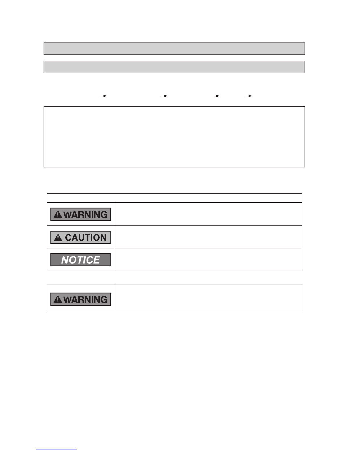
Signal Words
Indicates a hazardous situation that, if not avoided, could result in death
or serious injury.
Indicates a hazardous situation that, if not avoided, could result in minor or
moderate injury.
Indicates information considered important, but not hazard-related (for
example, messages relating to property damage).
General Precautions
To reduce the risk of serious injury or death, read these instructions
thoroughly and follow all warnings or cautions included in all manuals
that accompanied the product and are attached to the unit. Refer back to
these safety instructions as needed.
● This system should be installed by personnel certied by Johnson Controls, Inc. Personnel must be
qualied according to local, state and national building and safety codes and regulations. Incorrect
installation could cause leaks, electric shock, re or explosion. In areas where Seismic ‘’Performance
requirements are specied, the appropriate measures should be taken during installation to guard
against possible damage or injury that might occur in an earthquake if the unit is not installed
correctly, injuries may occur due to a falling unit.
● Use appropriate Personal Protective Equipment (PPE), such as gloves and protective goggles and,
where appropriate, have a gas mask nearby. Also use electrical protection equipment and tools
suited for electrical operation purposes. Keep a quenching cloth and a re extinguisher nearby during
brazing. Use care in handling, rigging, and setting of bulky equipment.
● When transporting, be careful when picking up, moving and mounting these units. Although the
unit may be packed using plastic straps, do not use them for transporting the unit from one location
to another. Do not stand on or put any material on the unit. Get a partner to help, and bend with
your knees when lifting to reduce strain on your back. Sharp edges or thin aluminum ns on the air
conditioner can cut ngers, so wear protective gloves.
Read following sections carefully before installing this product.
Read over the "Installation and Maintenance Manual" for the outdoor unit as well.
Page 6
2
PMGB0400B-rev.2
● Do not touch or adjust any safety devices inside the indoor or outdoor units. All safety features,
disengagement, and interlocks must be in place and functioning correctly before the equipment is put
into operation. If these devices are improperly adjusted or tampered with in any way, a serious accident
can occur. Never bypass or jump-out any safety device or switch.
● Before servicing, turn-OFF the power supply and use accepted lockout and tag out procedures at all
main switches.
● This unit is the pressurized system. Never loosen threaded joints while the system is under pressure
and never open pressurized system parts.
● Johnson Controls will not assume any liability for injuries or damage caused by not following steps
outlined or described in this manual. Unauthorized modications to Johnson Controls products are
prohibited as they…
◦ May create hazards which could result in death, serious injury or equipment damage;
◦ Will void product warranties;
◦ May invalidate product regulatory certications;
◦ May violate OSHA standards;
Take the following precautions to reduce the risk of property damage.
● Be careful that moisture, dust, or variant refrigerant compounds not enter the refrigerant cycle during
installation work. Foreign matter could damage internal components or cause blockages.
● If air lters are required on this unit, do not operate the unit without the air lter set in place. If the air
lter is not installed, dust may accumulate and breakdown may result.
● Do not install this unit in any place where silicon gases can coalesce. If the silicon gas molecules
attach themselves to the surface of the heat exchanger, the nned surfaces will repel water. As a
result, any amount of drainage moisture condensate can overow from the drain pan and could run
inside of the electrical box, possibly causing electrical failures.
● When installing the unit in a hospital or other facility where electromagnetic waves are generated
from nearby medical and/or electronic devices, be prepared for noise and electronic interference
Electromagnetic Interference (EMI). Do not install where the waves can directly radiate into the
electrical box, controller cable, or controller. Inverters, appliances, high-frequency medical equipment,
and radio communications equipment may cause the unit to malfunction. The operation of the unit
may also adversely affect these same devices. Install the unit at least 10 ft. (3m) away from such
devices.
● When a wireless controller is used, locate at a distance of at least 3.3 ft. (1m) between the indoor
unit and electric lighting. If not, the receiver part of the unit may have difculty receiving operation
commands.
● Do not install the unit in any location where animals and plants can come into direct contact with the
outlet air stream. Exposure could adversely affect the animals and plants.
● Do not install the unit with any downward slope to the side of the drain adaptor. If you do, you may
have drain water owing back which may cause leaks.
● Be sure the drain hose discharges water properly. If connected incorrectly, it may cause leaks.
● Do not install the unit in any place where oil can seep onto the units, such as table or seating areas in
restaurants, and so forth. For these locations or social venues, use specialized units with oil-resistant
features built into them. In addition, use a specialized ceiling fan designed for restaurant use. These
specialized oil-resistant units can be ordered for such applications. However, in places where large
quantities of oil can splash onto the unit, such as a factory, even the specialized units cannot be used.
These products should not be installed in such locations.
Installation Precautions
To reduce the risk of serious injury or death, the following installation
precautions must be followed.
● When installing the unit into…
▫ A wall: Make sure the wall is strong enough to hold the unit’s weight. It may be necessary to
construct a strong wood or metal frame to provide added support.
▫ A room: Properly insulate any refrigerant tubing run inside a room to prevent “sweating” that can
cause dripping and water damage to wall and oors.
Page 7

PMGB0400B-rev.2
3
▫ Damp or uneven areas: Use a raised concrete pad or concrete blocks to provide a solid, level
foundation for the unit to prevent water damage and abnormal vibration.
▫ An area with high winds: Securely anchor the outdoor unit down with bolts and a metal frame.
Provide a suitable air bafe.
▫ A snowy area: Install the outdoor unit on a raised platform that is higher than drifting snow. Provide
snow vents.
● Do not install the unit in the following places. Doing so can result in an explosion, re, deformation,
corrosion, or product failure.
▫ Explosive or ammable atmosphere
▫ Where a re, oil, steam or powder can directly enter the unit, such as nearby or above a kitchen
stove.
▫ Where oil (including machinery oil) may be present.
▫ Where corrosive gases such as chlorine, bromine, or sulde can accumulate, such as near a hot
tub or a hot spring.
▫ Where dense, salt-laden airow is heavy, such as in coastal regions.
▫ Where the air quality is of high acidity.
▫ Where harmful gases can be generated from decomposition.
● Do not position the drain pipe for the indoor unit near any sanitary sewers where corrosive gases
may be present. If you do, toxic gases can seep into breathable air spaces and can cause respiratory
injuries. If the drain pipe is installed incorrectly, water leakage and damage to the ceiling, oor,
furniture, or other possessions may result. If the drain pipe becomes clogged, water may drip from the
indoor unit. Do not install the indoor unit where such dripping can cause moisture damage or uneven
locations: Use a raised concrete pad or concrete blocks to provide a solid, level foundation for the unit
to prevent water damage and abnormal vibration.
● Before performing any brazing work, be sure that there are no ammable materials or open ames
nearby.
● Perform a test run to ensure normal operation. Safety guards, shields, barriers, covers, and protective
devices must be in place while the compressor/unit is operating. During the test run, keep ngers and
clothing away from any moving parts.
● Clean up the site when nished, remembering to check that no metal scraps or bits of wiring have
been left inside the unit being installed.
After installation work for the system has been completed, explain the “Safety Precautions,” the proper use
and maintenance of this unit to the customer according to the information in all manuals that came with the
system. All manuals and warranty information must be given to the user or left near the Indoor Unit.
Page 8
4
PMGB0400B-rev.2
Refrigerant Precautions
To reduce the risk of serious injury or death, the following refrigerant
precautions must be followed.
● As originally manufactured, this unit contains refrigerant installed by Johnson Controls. Johnson
Controls uses only refrigerants that have been approved for use in the unit’s intended home country
or market. Johnson Controls distributors similarly are only authorized to provide refrigerants that
have been approved for use in the countries or markets they serve. The refrigerant used in this unit
is identied on the unit’s faceplate and/or in the associated manuals. Any additions of refrigerant into
this unit must comply with the country’s requirements with regard to refrigerant use and should be
obtained from Johnson Controls distributors. Use of any non-approved refrigerant substitutes will void
the warranty and will increase the potential risk of injury or death.
● If installed in a small room, take measures to prevent the refrigerant from exceeding the maximum
allowable concentration in the event that refrigerant gases should escape. Refrigerant gases can
cause asphyxiation (0.026 lbs/ft
3
(0.42 kg/m3) based on ISO 5149 for R410A). Consult with your
distributor for countermeasures (ventilation system and so on). If refrigerant gas has leaked during the
installation work, ventilate the room immediately.
● Before installation is complete, make sure that the refrigerant leak test has been performed. If
refrigerant gases escape into the air, turn OFF the main switch, extinguish any open ames and
contact your service contractor. Refrigerant (Fluorocarbon) for this unit is odorless. If the refrigerant
should leak and come into contact with open ames, toxic gas could be generated. Also, because the
uorocarbons are heavier than air, they settle to the oor, which could cause asphyxiation.
● When installing the unit, and connecting refrigerant piping, keep all piping runs as short as possible,
and make sure to securely connect the refrigerant piping before the compressor starts operating. If
the refrigerant piping is not connected and the compressor activates with the stop valve opened, the
refrigerant cycle will become subjected to extremely high pressure, which can cause an explosion or re.
● Tighten the are nut with a torque wrench in the specied manner. Do not apply excessive force to the
are nut when tightening. If you do, the are nut can crack and refrigerant leakage may occur.
● A compressor/unit comprises a pressurized system. Never loosen threaded joints while the system is
under pressure and never open pressurized system parts.
● When maintaining, relocating, and disposing of the unit, dismantle the refrigerant piping after the
compressor stops.
Electrical Precautions
Take the following precautions to reduce the risk of electric shock, re or
explosion resulting in serious injury or death.
● Highly dangerous electrical voltages are used in this system. Carefully refer to the wiring diagram and
these instructions when wiring. Improper connections and inadequate grounding can cause serious
injury or death.
● Before servicing, open and tag all disconnect switches. Never assume electrical power is
disconnected. Check with meter and equipment.
● Only use electrical protection equipment and tools suited for this installation.
● Use specied cables between units.
● Communication cable should be a minimum of AWG18 (0.82mm
2
), 2-Conductor, Stranded Copper.
Shielded cable must be considered for applications and routing in areas of high EMI and other
sources of potentially excessive electrical noise to reduce the potential for communication errors.
When shielded cable is applied, proper bonding and termination of the cable shield is required as per
Johnson Controls guidelines. Plenum and riser ratings for communication cables must be considered
per application and local code requirements.
● Use an exclusive power supply for the air conditioner at the unit’s rated voltage.
● Be sure to install circuit breakers (ground fault interrupter, isolating switch, molded case circuit
breaker and so on), with the specied capacity. Ensure that the wiring terminals are tightened
securely to recommended torque specications. If a circuit breaker or fuse is frequently activated,
shut down the system and contact your service contractor.
Page 9

PMGB0400B-rev.2
5
● Clamp electrical wires securely with a cable clamp after all wiring is connected to the terminal block.
In addition, run wires securely through the wiring access channel.
● When installing the power lines, do not apply tension to the cables. Secure the suspended cables at
regular intervals, but not too tightly.
● Make sure that the terminals do not come into contact with the surface of the electrical box. If the
terminals are too close to the surface, it may lead to failures at the terminal connection.
● Turn OFF and disconnect the unit from the power supply when handling the service connector. Do not
open the service cover or access panel to the indoor or outdoor units without turning OFF the main
power supply.
● After stopping operation, be sure to wait at least ve minutes before turning off the main power
switch. Otherwise, water leakage or electrical breakdown may result. Disconnect the power supply
completely before attempting any maintenance for electrical parts. Check to ensure that no residual
voltage is present after disconnecting the power supply.
● Do not clean with, or pour water into, the controller as it could cause electric shock and/or damage the
unit. Do not use strong detergent such as a solvent. Clean with a soft cloth.
● Check that the ground wiring is securely connected. Do not connect ground wiring to gas piping,
water piping, lighting conductor, or telephone ground wiring.
● If a circuit breaker or fuse is frequently activated, shut down the system and contact your service
contractor.
● This equipment can be installed with a Ground Fault Circuit Breaker (GFCI), which is a recognized measure for
added protection to a properly grounded unit. Install appropriate sized breakers / fuses / overcurrent protection
switches, and wiring in accordance with local, state and NEC codes and requirements. The equipment installer
is responsible for understanding and abiding by applicable codes and requirements.
Page 10
6
PMGB0400B-rev.2
● Proper handling of this unit requires two people. Safe handling and installing of the indoor unit requires
the strength of two people. Mounting the unit alone may cause injury due to a fall of the unit. Although
the unit may be girded with steel banding, do not use it for transportation. Avoid contact with nned
surfaces of the heat exchanger as sharp edges can cause severe injury to hands and ngers. Use
appropriate work gloves for the job.
NOTICE
● Check to ensure that the drain hose discharges moisture properly. If connected incorrectly, it can result in
leakage and damage to furniture.
● Do not apply an excessive force to the drain pipe connection. This can also compromise the seal
properties of the connection.
● Verify that the installed unit is level with oor and ceiling surfaces. Any variance or inclination can cause
moisture to back up into the drain pan, overow, and seepage onto ceiling or wall surfaces, and cause
damage to carpeted surfaces or furniture below.
● Do not install this system in close proximity to septic sewer lines where ammable and toxic gases can coalesce.
● Inspect the drain pan before the onset of winter to drain away all accumulated moisture in the pan.
● The heat exchanger of indoor unit overheats whenever there is a slight amount of refrigerant circulating
during slowdown or stoppage. As a result, moisture in the drain pan evaporates where it can condense on
ceiling or wall surfaces.
● After the drain check is completed, insert the rubber plug again and seal the gap with a silicone sealant.
Electrical Installation
In some cases, the packaged air conditioner may not be operated normally under the following cases:
● When electrical power for the packaged air conditioner is supplied from the same power transformer
as the device*.
● When the power supply wiring for the device* and the packaged air conditioner are located close to
each other:
Device*(Example): Lift, container crane, rectier for electric railway, inverter power device, arc
furnace, electric furnace, large-sized induction motor, and large-sized switch.
It consumes large quantities of electrical power.
Regarding that mentioned above, surge voltage may be inducted into the power supply wiring for the crated
air conditioner due to a spike in power consumption for this device and an activation of the switch. Check
the eld regulations and standards before performing any electrical work in order to safeguard the power
supply for the crated air conditioning unit.
Page 11
PMGB0400B-rev.2
7
3. Before Installation
NOTES:
● If the Damper Minimum Setting (optional function d7) of this indoor unit is set to higher step then this will
affect the air outlet temperature of other standard indoor units.
● Airow volume must be at lower limit for All Fresh operation.
3.2 Working Range
This heat pump air conditioner has been designed for the following temperatures. Operate the heat pump air
conditioner within this range.
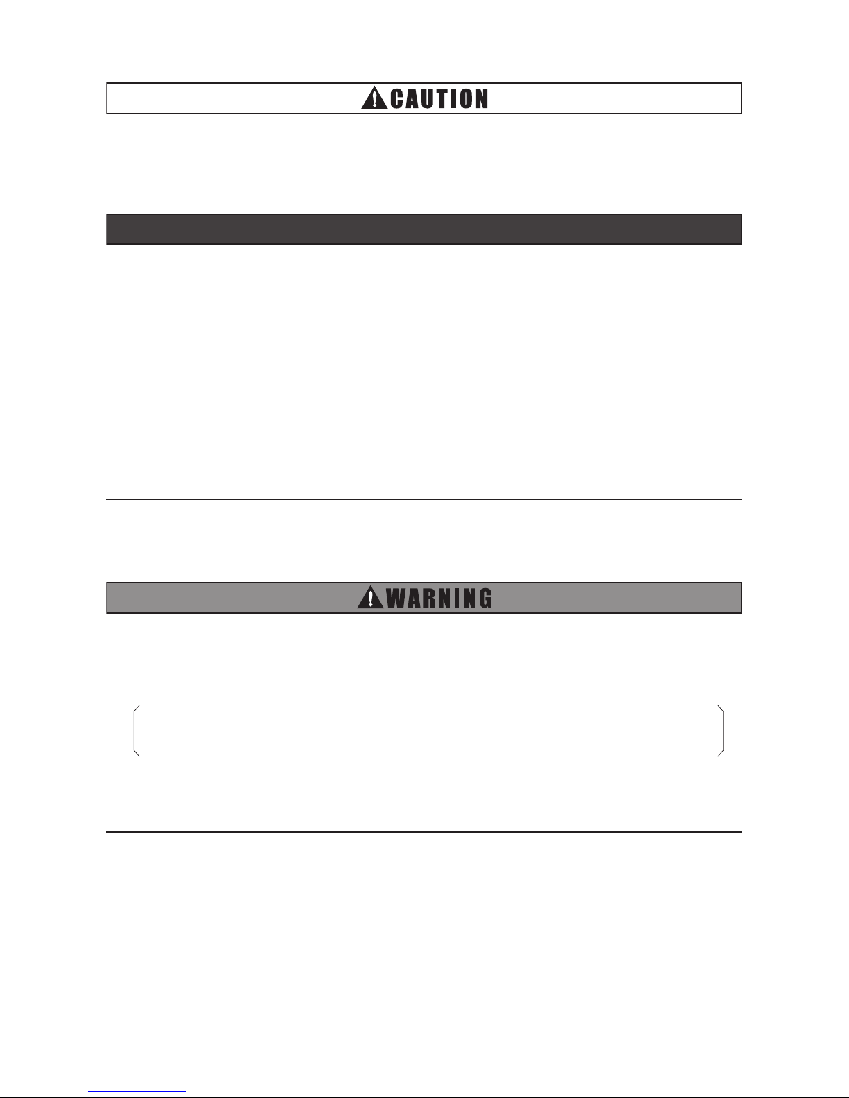
< Cooling Mode Operation Range >
23
(-5
)
32
(0)
50
(10)
(*1) (*2)68
(20)
86
(30)
104
(40)
109
(43)
92
(33.5)95(35)
89 (32)
64
(18)
Air Inlet Wet Bulb Temperature
(Outdoor Temperature) (
o
F (
o
C) WB)
Air Inlet Dry Bulb Temperature
(Outdoor Temperature) (
o
F (oC) DB)
41
(5)
Relative Humidity : 90%RH
Relative Humidity : 30%RH
Normal Cooling
Outdoor Air
Cooling
Normal Cooling
NOTES:
by the unit's outdoor thermistor.
5. Air inlet dry bulb temperature (outdoor temperature) indicates the temperature detected
2. Outdoor air damper of this unit may remain opened at “Damper Minimum Opening” setting
1. Make sure to apply extra insulation on the unit and duct to prevent condensation when the
outdoor temperature is low.
4. Compressor is stopped during outdoor air cooling.
3. Unit may not operate when the outdoor temperature is high for All Fresh mode. (*2)
(optional function d7) or prohibits OA intake for All Fresh mode below 41
o
F (5oC). (*1)
3.1 Combination of Outdoor Unit and Indoor Unit
Indoor units can be connected with the outdoor unit (VRF system).
Outdoor Unit Type Combination of Outdoor Unit and Indoor Unit
VRF Standard
VRF Less Module
VRF Mini
Ducted with
EconoFresh Kit only
Total capacity of Ducted with EconoFresh Kit is
70%~100% of the outdoor unit capacity.
Ducted with
EconoFresh Kit
+
Other Standard
Indoor Unit
Total capacity of Ducted with EconoFresh Kit is
30% or below the outdoor unit capacity.
AND
Total capacity of indoor unit (including Ducted with EconoFresh Kit) is
70%~100% of the outdoor unit capacity.
VRF Low Ambient
Ducted with
EconoFresh Kit only
Total capacity of Ducted with EconoFresh Kit is
55%~80% of the outdoor unit capacity.
Ducted with
EconoFresh Kit
+
Other Standard
Indoor Unit
Total capacity of Ducted with EconoFresh Kit is
20% or below the outdoor unit capacity.
AND
Total capacity of indoor unit (including Ducted with EconoFresh Kit) is
55%~80% of the outdoor unit capacity.
Page 12
8
PMGB0400B-rev.2
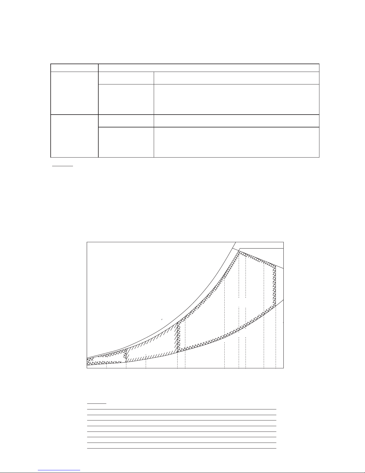
< Heating Mode Operation Range >
23
(-5
)
32
(0)
50
(10)
(*1) (*2)68
(20)
86
(30)
104
(40)
109
(43)
92
(33.5)95(35)
89 (32)
Air Inlet Wet Bulb Temperature
(Outdoor Temperature) (
o
F (
o
C) WB)
Air Inlet Dry Bulb Temperature
(Outdoor Temperature) (
o
F (oC) DB)
75
(24)
41
(5)
Normal Heating
Outdoor Air
Heating
Relative Humidity : 30%RH
Relative Humidity : 90%RH
NOTES:
by the unit's outdoor thermistor.
5. Air inlet dry bulb temperature (outdoor temperature) indicates the temperature detected
the outdoor temperature is low.
6. Make sure to apply extra insulation on the unit and duct to prevent condensation when
1. Make sure the air inlet wet bulb temperature (outdoor temperature) is below 59
o
F WB (15oC WB).
4. Compressor is stopped during outdoor air heating.
3. Unit may not operate when the outdoor temperature is high for All Fresh mode. (*2)
(optional function d7) or prohibits OA intake for All Fresh mode below 41
o
F (5oC). (*1)
2. Outdoor air damper of this unit may remain opened at “Damper Minimum Opening” setting
Page 13

PMGB0400B-rev.2
9
3.4 Factory-Supplied Accessories
Check to ensure that the following accessories are packed with the indoor unit.
3.3 Transportation and Handling
•
Transport the product as close to the installation location as possible before unpacking.
•
Do not lay any objects on the indoor unit.
•
The indoor unit comes crated upside-down with the foam polystyrene drain pan positioned on top.
Do not invert the unit until it is ready to be suspended above the oor. Inverting the unit while on the oor
will crush the drain pan. Do not handle the unit by grabbing at the polystyrene pan and other air outlets
as they are fragile and will sustain damage.
•
The indoor unit handle is fabricated from foam polystyrene and is susceptible to breakage if any
excessive force is applied as a result of mishandling of the unit during installation.
NOTICE
3.5 Necessary Tools and Instrument List for Installation
NOTE:
Use tools and measuring
instruments (vacuum pump, gas
hose, charging cylinder, manifold
gauge) exclusively for refrigerant
R410A.
No. Tool No. Tool
1 Handsaw 11 Wrench
2 Phillips Screwdriver 12 Charging Cylinder
3 Vacuum Pump 13 Manifold Gauge
4 Refrigerant Gas Hose 14 Wire Cutter
5 Megohmmeter 15 Gas Leak Detector
6 Copper Pipe Bender 16 Level
7 Manual Water Pump 17 Clamps for Solderless Terminals
8 Pipe Cutter 18 Hoist (for Indoor Unit)
9 Brazing Kit 19 Ammeter
10 Hex Wrench 20 Voltage Meter
Controller and branch piping are optional accessories which are not included with the indoor unit.
If necessary, please contact your distributor or contractor.
Accessory PurposeQty.
Cable Clamp
5
PVC Tube
2
For Fixing PVC Tube
For Separating Communication Cables and
Wired Controller Cables from Power Supply Wirings
ID 1/2 inch (12mm)
Page 14

10
PMGB0400B-rev.2
4. Installation Location
Figure. 4.1 Operation and Installation Space
(1) Install the indoor unit, allowing for proper
clearance for operation and maintenance
access, as shown in Figure. 4.1.
(2) Consider the air distribution from the indoor unit to the space of the room, and select a suitable location
so that uniform air temperature in the room can be obtained.
(3) Do not leave combustible materials inside the service space of the indoor unit.
(4) Avoid obstacles which may hamper the air intake or the air discharge ow.
(5) Do not install the indoor unit in a machine shop, kitchen, or similar space where vapor from oil or its mist
can reach the indoor unit.
Oil will deposit on the heat exchanger, thereby reducing the indoor unit performance, and may deform
and in the worst case, break the plastic parts of the indoor unit.
(6) Pay attention to the following points when the indoor unit is installed in a hospital or other facilities
where there are electronic waves from medical equipment.
(a) Do not install the indoor unit where the electromagnetic wave is directly radiated to the electrical
box, communication cable or wired controller.
(b) Install the indoor unit and components as far away as practical or at least 9.8ft (3m) from any
electromagnetic wave radiator.
(c) Prepare a steel box and install the wired controller in it. Prepare a steel conduit tube and wire the
controller cable in it. Then, connect the ground wiring with the box and the tube.
(d) Install a noise lter if the power supply emits harmful noises.
(7) To avoid any corrosive action to the heat exchangers, do not install the indoor unit in an acid or alkaline
environment.
Install the indoor unit in a compartment handling air for circulation through a duct supplying
only one room.
Rear Side
≥ 15-3/4
(400)
≥ 39-3/8
(1000)
View from Top
Front Side
(5-1/8 (130))
≥ 23-5/8
(600)
≥ 23-5/8
(600)
Electrical Box
Unit: inch (mm)
Service Access Door
(≥ □17-11/16 (450))
If the ceiling board
cannot be found
for servicing,
prepare a service
access door
below the indoor
unit for removing
the indoor unit.
Page 15

PMGB0400B-rev.2
11
5.1 Positions of Suspension Bolts and Piping Connections
(1) Mark off the positions for the suspension bolts, refrigerant pipe connections, and drain pipe connection.
(2) Installation dimensions are shown in Figure 5.1.
Refer to “Installation Manual” for EconoFresh Kit to install the EconoFresh Kit.
58-1/16 (1474) 13/16 (20)
13-3/4 (350) 13-3/4 (350) 13-3/4 (350)
49-9/16 (1259)
3/8 (10)
Around the Flange
3-3/4 (96)
61-9/16 (1564)
Air Outlet
1-9/16 (39)
6-15/16
(176)
6-7/8 (174)
2-3/8 (60)
3-11/16 (94)
3/8 (10)
10-7/8 (276)
7/8 (23)21-13/16 (554)
(for Suspension Bolt)
7/8 (23)
1-1/4 (31)
23-5/8 (600)
1-1/8 (29)
26 (660)
59-5/8 (1514) (for Suspension Bolt)
(for Suspension Bolt)
Electrical Control Box
Air Inlet (Indoor Air) Air Inlet (Outdoor Air)
Around the Flange for
Outdoor Duct Connection
7-7/8 (200)
Around the Flange for
Indoor Duct Connection
3-1/4
(82)
1-5/16
(34)
4-1/8
(104)
4-1/8
(104)
7-1/8
(181)
13/16
(20)
3-1/4
(82)
3-15/16
(100)
11-13/16 (300)
8 x φ1/4 (7) 10 x φ1/4 (7)
12 x φ1/8 (3)
2 x φ1/8 (3)
4 - φ1-1/4 (31) x 1/2 (12)
4 - φ9/16 (15) x 1/2 (12)
18-1/4 (464)
27-3/8 (696)
1-3/4 (45)
1-7/8 (48)
11-13/16 (300) 11-13/16 (300)
1-7/8 (48)
54-5/16 (1380)
1/4 (7) 12-9/16 (319)
2-3/16 (55)
(for Suspension Bolt)
55-1/2 (1410)
1-1/4 (32)
8-9/16 (217)
7/8 (22)
2-3/8 (60)
10 (254)
53-1/8 (1350)
2-5/16 (59)
A
View from A
A
Drain Pipe Connection
Upper: Refrigerant Gas Pipe Connection
Lower: Refrigerant Liquid Pipe Connection
3-5/8 (92)
10-1/16 (255)
5. Installation Work
Figure 5.1 Installation Dimensions
5.2 Installation of Suspension Bolts
(1) Determine the nal location and installation
orientation of the indoor unit with respect
to the space allowed for piping, wiring, and
maintenance access.
(2) Mount suspension bolts, as shown in Figure
5.2.
5-7/8 to 6-5/16 inches
(150 to 160mm)
Insert
220 to 330 lb
(100 to 150kg)
I Beam
Suspension Bolt
(W3/8 or M10)
Anchor Bolt
(W3/8 or M10)
Steel
Concrete
For Wooden Beam Suspension
Wooden Bar
2-3/8 to 3-9/16 inches Square
(60 to 90mm)
Wooden Beam
Nut
Nut
Square Washer
Square Washer
For Concrete Slab For Steel Beam
Suspension Bolt
(W3/8 or M10)
Figure. 5.2 Mounting of Suspension Bolts
inch (mm)
Page 16

12
PMGB0400B-rev.2
Figure 5.5 Suspended Indoor Unit
(2) Suspending the Indoor Unit
* Hook the suspension bracket to the nut and washer of each hanging bolt as shown, starting at the
opposite side and working over to the service cover side.
* After verifying that the nut and washer are correctly afxed to the retainers on the suspension bracket,
hook the suspension bracket of the service cover side to the nut and washer.
(Install the suspension bolts away from the unit when fastening.)
Figure 5.4 Nuts and Washers
(1) How to install Nuts and Washers on Suspension Bolts
Install nuts and washers on each of the four
suspension bolts, as shown in Figure 5.4.
Approx.
2 inches (50mm)
Washer
Nut
Washer
Indoor Unit
Nut
Suspension Bolt
Suspension Bracket
Suspension
Bracket
Nut and
Washer
Right Side
(Electrical Box Cover Side)
Indoor Unit
Left Side
5.3 Mounting Indoor Unit
Hang the indoor unit as shown in Figure 5.3.
Field-Supplied Parts
* Suspension Bolts: 4-M10 or W3/8
* Nut and Washer: 8-M10 or W3/8
Suspension
Bracket
Suspension Bolts (4-M10 or W3/8)
(Field-Supplied)
False Ceiling Side
Nut & Washer
(8-M10 or W3/8)
(Field-Supplied)
Unit
Figure 5.3 Mounting Indoor Unit
Page 17

PMGB0400B-rev.2
13
5.4 Adjusting Level of Unit
(1) Use a level to verify that the unit base is level with the oor.
3/16 inch
(5mm)
Figure 5.6 Foundation Gradient
(2) The unit should be installed so that the right side of the unit is slightly (0 to 3/16 inch (0 to 5mm)) lower
than the left side to allow and promote drainage discharge.
(3) Tighten the bolts of the suspension nuts with the suspension brackets after adjustment is completed.
Special threadlocking compound must be applied to the bolts in order to prevent them from loosening.
NOTE:
During the installation process, keep the unit well covered with vinyl cover and related components
covered until it is time to hoist into position.
5.5 Ducting Arrangement
This unit has been designed for positive introduction of the outdoor air for free cooling or other control. Check
to ensure that the following points have been previously designed or arranged.
5.5.1 Pressure Drop of Outdoor Air Duct
In order to protect against a shortage of outdoor air intake or excessive intake of outdoor air, which causes
insufcient capacity of free cooling or uncomfortable change of supply air during free cooling operation,
keep the pressure drop of the outdoor air duct within the following guide range:
1/2 P
R
< PO < 4 x P
R
PR: Pressure Loss of Return Air Duct at Designed Supply Air Volume
PO: Pressure Loss of Outdoor Air Duct at Designed Supply Air Volume, Including the Outdoor Air Filter
5.5.2 Pressure Relief Damper
When the building is of an air-tight structure, positive pressure inside the building will be created during the
free cooling or all-fresh operation.
The balance between the outdoor air volume and the return air volume depends on the arrangement of the
discharge air duct, return air duct, and installed duct arrangement.
NOTICE
Page 18

14
PMGB0400B-rev.2
5.6 Example of Installation
5.6.1 Ducting Connection
Pre-drilled duct anges are provided at the supply, return and outdoor air intake connections. It is
recommended that a exible duct connection be installed to minimize sound and vibration transmission.
5.6.2 Insulation
All ducts should be insulated.
● Especially the outdoor air duct, through which the cold outdoor air ows in, must be sufciently insulated.
● The lowest temperature of the entering outdoor air owing through the outdoor air duct is the lowest
temperature for heating operation at the installation site.
● If the unit is used under high relative humidity around the unit or cold outdoor airows in, perform
additional insulation (*) to the unit and ducts or prepare a drain pan underneath the unit.
Figure 5.7 Example of Installation
Ducting arrangement must comply with local codes.
NOTICE
Supply Air Duct
(H,Y,C)IDM***B21E Unit
(*) Insulation (Field-Supplied)
EconoFresh Kit
Return Air
Duct
Return Air Filter
(Field-Supplied)
Pressure Relief
Damper
(If Required)
Rain Hood with
Bird Screen
(Field-Supplied)
Outdoor Thermistor
(Accessory)
Downward
Gradient of Duct
Outdoor Air Duct
(Fully Insulated)
(Field-Supplied)
Thermistor
Cable
Relay Wire for
Damper Motor
(Accessory)
Refrigerant
Piping
(*) (*)
Page 19

PMGB0400B-rev.2
15
5.7 Connecting Supply Duct
(1) An air lter is not included with accessories of the unit. Install the air lters in the duct of air inlet side
which has higher than 50% of dust-collecting efciency.
(2) If reducing the noise by the indoor unit is necessary, install silencers (eld-supplied).
(3) The canvas ducts should be connected between the indoor unit and the supply duct as shown next
page in order to avoid abnormal sound vibration.
(4) Attach vibration-proof rubber gasket (eld-supplied) to suspension bolts in order to avoid abnormal
sound vibration.
(5) Design the duct arrangement as “Unit External Static Pressure = Duct Pressure Loss + Suction/
Discharge Pressure Loss”. If the duct design is not correct, a louder noise, splashing water, etc., will
occur. The damper or the duct fan, etc., should be used to adjust the fresh air volume to let the unit's
external static pressure be approximately within pressure loss of duct.
(6) If pressure loss of duct is excessive, change the installation location of the unit or the shape of ducts in
order to let the design arrangement be within the unit's external static pressure.
(7) Make sure that a service access panel is mounted on the ceiling for the service of electrical parts,
motor, etc. If the service access panel can not be mounted on the ceiling, an alternative opening should
be prepared on the ceiling. It should be a suitable size for the indoor unit to be installed and removed
easily and for a fan, a heat exchanger and a drain pan to be installed through it.
(8) Install thermal insulations over the duct to prevent it from dew condensation.
(9) Do not install the duct in the following places.
- Places where there is direct radiant heat from sunlight or heat sources.
- Places where corrosive gases, volatile gases and explosive gases are generated.
- Places where air intake such as a kitchen or similar where vapor from oil or its mist ows to the indoor
unit.
In addition, install a protection hood and cover the air inlet with a net or similar to stop any insects or
small animals from entering.
(10) Conduct periodic maintenance of the air lter and a periodic check for clogging of condensate piping
carefully when the indoor unit is installed where there is a lot of activity. Be extra mindful when installing
in places where strong salty wind can be present (coast region, etc.). Consult with your distributor for
countermeasures for periodic maintenance and contract to replace the heat exchanger.
(11) Install the ducts with the air inlet being at a lower level than the indoor unit to protect the unit from rain.
(12) If the indoor is negative pressure while this indoor unit stopped, outdoor air may enter the room through
the indoor unit. Outdoor intake shutter should be provided.
Otherwise, following problems may occur.
● Condensation buildup on the ducts and indoor units when outdoor temperature is low.
● Affects air conditioning load and uncomfortableness when outdoor temperature is high.
Page 20

16
PMGB0400B-rev.2
5.8 Setting the EconoFresh Pressure Mode
Refer to Section 8.6 "EconoFresh Pressure Mode Setting".
Model (H,Y,C)IDM030B21E (H,Y,C)IDM036B21E (H,Y,C)IDM048B21E
Static Pressure
in.W.G.
(Pa)
0.15 - 0.11 - 0.09
(37 - 27 - 22)
0.13 - 0.11 - 0.09
(32 - 28 - 22)
0.11 - 0.10 - 0.08
(27 - 25 - 20)
Above values are based on EconoFresh Pressure Mode, OA 100% and at 3 different speeds (Hi, Me, Lo).
Figure 5.8 Duct Connection Example
An air filter which
can collect dust.
Outdoor Air
Damper for
Adjusting Air Volume
DamperSilencer Canvas DuctCanvas Duct
Thermal
Insulation
Damper for
Fine Adjusting
Air Volume
Air Outlet
Horizontal
Air Inlet
(with Air Filter)
EconoFresh Kit
Indoor
Unit
Service Access Panel
(17-11/16 inches x 17-11/16 inches)
Page 21

PMGB0400B-rev.2
17
6. Refrigerant Piping Work
Table 6.1 Piping Size
inch (mm)
Model Gas Piping Liquid Piping
(H,Y,C)IDM030B21E
(H,Y,C)IDM036B21E
(H,Y,C)IDM048B21E
5/8 (15.88) 3/8 (9.52)
(3) Prepare the eld-supplied copper piping.
(4) Select clean copper pipes. Make sure there is no dust and moisture inside.
(5) The refrigerant oil used in combination with refrigerant R410A is susceptible to moisture, oxide lm, oil,
and fat. Exercise special care during the installation so that moisture, particulate contamination, or old
refrigerant oil will not enter the refrigerant cycle. Otherwise, impurities may adhere to the expansion
valve and it may prevent the proper operation.
(6) Caution: When cutting piping, do not use tools such as saws and a grinding wheel. They can produce
harmful metallic lings that can damage a refrigerant system. Use a pipe cutter to eliminate any metal
lings. After the cut is made, blow out each pipe with dry compressed air or nitrogen to remove this
residue before making pipe connections.
6.1 Piping Materials
(1) Tolerances for refrigerant piping lengths depend on the combination with the outdoor unit. Refer to the
“Installation and Maintenance Manual” for the outdoor unit for details.
(2) Select the piping size from the following table.
For details on refrigerant piping work, vacuum pump, and refrigerant charge, refer to the "Installation and
Maintenance Manual" for the outdoor unit.
Use the specied non-ammable refrigerant (HFC R410A) for the outdoor unit. Do not charge the unit
with anything other than HFC R410A, such as hydrocarbon refrigerants (propane and Isobutene),
oxygen, and other ammable gases (acetylene, ammonia, and so forth), or any poisonous gases
when installing, maintaining and moving the unit. These substances are volatile and dangerous and
can result in re, explosion, and serious or fatal injuries.
In Case of Getting the Pipe
Through a Hole in the Wall
Correct
CorrectIncorrect Incorrect
Correct Incorrect
HoleHole
Attach a cap or put a plastic bag
over the pipe end.
Attach a cap or put a plastic
bag over the pipe end.
Attach a cap or put a plastic
bag over the pipe end.
Rubber Band
Do not lay the pipe
directly on the ground.
Rain water
can come in.
In Case of Rain
Page 22

18
PMGB0400B-rev.2
inch (mm)
Diameter
(d)
A
+0
-0.02 (-0.4)
1/4 (6.35) 0.36 (9.1)
3/8 (9.52) 0.52 (13.2)
1/2 (12.7) 0.65 (16.6)
5/8 (15.88) 0.78 (19.7)
(2) Perform the aring work as shown.
6.2 Piping Connection Work
(3) Use the are nut shipped with the unit.
(4) Verify that there are no scratches, burrs stuck to internal surfaces, or surface deformations at the ared
opening.
(5) Before tightening the are nut, apply the refrigerant oil (eld-supplied) in a thin layer over the ared part.
(Do not apply the oil on other areas.) Tighten the are nut for the liquid pipe to the specied torque with
two spanners. Then, tighten the are nut for the gas piping in the same way. After tightening, check that
no refrigerant leakage occurs.
NOTE:
Refrigerant oil is eld-supplied.
[ Ethereal Oil FVC50K, FVC68D (Idemitsu Kousan Co. Ltd.) ]
0.016 ~ 0.031R
φA
φd
90
o
+
2
o
45
o
+
2
o
Required Tightening Torque (JIS B 8607)
Pipe Size Tightening Torque
1/4 inch (6.35 mm) 10.3 - 13.3 ft·lbs (14 - 18 N·m)
3/8 inch (9.52 mm) 25.1 - 31.0 ft·lbs (34 - 42 N·m)
1/2 inch (12.7 mm) 36.1 - 45.0 ft·lbs (49 - 61 N·m)
5/8 inch (15.88 mm) 50.2 - 60.5 ft·lbs (68 - 82 N·m)
3-9/16 (91) (Refrigerant Gas Pipe Connection)
3-3/4 (96) (Drain Pipe Connection)
10-1/16 (255)
3-5/8 (92)
2-3/8
(60)
3-1/16 (78)
4-5/16 (109)
2-3/4 (70) (Refrigerant Liquid Pipe Connection)
6-
Drain Pipe Connection VP25
Refrigerant Liquid Pipe Connection
Refrigerant Gas Pipe Connection
(1) Position of piping connection.
inch (mm)
Do not apply
the refrigerant
oil to the
outside of the
ared opening.
Apply Refrigerant Oil.
Page 23

PMGB0400B-rev.2
19
(6) Wherever buried piping exists on site, make sure there is adequate access to inspect piping sockets
and elbows, and for interconnecting parts.
(7) Piping must be reinforced to not be damaged by an external force.
(8) Make sure that the piping can accommodate expansion and contraction.
(9) Prevent the pipes from touching walls, ceiling, etc.
(10)Test for air-tight integrity. This should be done in accordance with the "Installation and Maintenance
Manual" for the outdoor unit.
(11) If temperature and humidity inside the room exceed 80.6°F (27°C)/RH80%, condensation occurs on
the surface of the insulation (eld-supplied). Wrap additional insulation (approximately 3/16~3/8 inch
(5~10mm) thickness) around the insulation (eld-supplied) of the refrigerant pipe as a preventive
measure.
(12) Insulate each are connection without gap with insulations (eld-supplied) to prevent condensation. Also
insulate each refrigerant pipe as well.
Fasten with cable clamps
at three locations along the pipe
(Field-Supplied).
Affix vinyl tape position at the vertical part
(Insulation for Refrigerant Pipe (Field-Supplied)).
Securely fasten cable clamps and vinyl tape
in order to prevent the accumulation of moisture.
Unit
Side
Check for any gap between
the indoor unit and the insulation.
Insulation Material
(Field-Supplied)
Insulation for
Refrigerant Pipe
(Field-Supplied)
Refrigerant Pipe
(Field-Supplied)
● Do not apply excessive force to the are nut when tightening. The are nut may crack due to stress
fracture and refrigerant leakage may occur. Use the correct torque specications.
● Make sure that a refrigerant leak test has been performed. Refrigerant (uorocarbon) for this unit
is non-ammable, non-toxic, and odorless. If the refrigerant should escape and come into contact
with ame, toxic gas will form. This gas is heavier than air and will settle near oor areas and
spread where it can cause asphyxiation to people.
Page 24

20
PMGB0400B-rev.2
(1) Figure 7.1 shows all drain piping connections.
(2) Prepare a PVC (Polyvinyl chloride) piping with 1-1/4 inches (32mm) outer diameter.
(3) Fasten the tube to the drain hose with glue and the eld-supplied clamp.
The drain piping must be done with a down-slope pitch of 1/25 to 1/100.
(4) Insulate the drain piping after connecting the drain hose.
7. Drain Piping
Perform drain piping work and attach the insulation before attempting any refrigerant piping work.
9-1/4 (235)
14-15/16 (380) 1 (25)
2-5/16
(58)
2-5/16
(58)
1 (25)
6-9/16
(166)
11-7/16 (291)
1-15/16 to 6-15/16
(50 to 176) (Max.)
14-3/4 to 19-11/16 (374 to 500) (Max.)
(Drain-Up Length)
Drain Piping (PVC Tube)
(Field-Supplied)
1/25 to 1/100 Down-Slope
inch (mm)
Suspension Bracket
(Field-Supplied)
90o Elbow Pipe
(Field-Supplied)
Lift Piping for Drain-Up
(PVC Tube)
(Field-Supplied)
Indoor Unit
Drain Pump
Drain
Pan
Drain Hose (L: 11-13/16 (300))
(Field-Supplied)
1 (25)
Figure 7.1 Drain Piping
Common
Drain Piping
Connection
1/25 to 1/100 Down-Slope
Common Drain Piping
This Drain pipe shall be
separated from other pipes.
Incorrect: Upward Slope
Unit
Rising Part
Incorrect
Correct
Indoor Unit
Auxiliary Drain Pan
(Field-Supplied)
To the Atmosphere
Figure 7.2 Auxiliary Drain Pan
NOTE:
If the relative humidity of ambient air exceeds
80%, install a (eld-supplied) auxiliary drain
pan beneath the indoor unit as shown in
Figure 7.2, if required.
Do not run drain piping into underground areas near sanitary or sewage lines where toxic and
corrosive gases can seep into the system. This can create a pathway for poisonous gas to penetrate
inhabited areas.
NOTICE
● Check to ensure that the drain hose discharges moisture properly. If connected incorrectly, it can cause
structural damage to the indoor wall and ceiling surfaces and damage the property.
● Avoid sloping the drain pipe upward as it will prevent drainage. Moisture may cause water leakage when
the unit operation stops.
● Do not connect drainage with sanitary or sewer lines or any other drain pipe.
● When the common drain pipe is connected with other indoor units, the connected position of each indoor
unit must be higher than the common pipe. The pipe size of the common drain pipe must be large enough
according to the drain from all the units.
● After performing drain piping work and electrical wiring, check to ensure that water ow follows.
Page 25

PMGB0400B-rev.2
21
After all drain piping work and electrical wiring is complete, verify that water ows correctly as follows:
Verication using a Float Switch
a. Turn ON the power supply.
b. Pour approximately 61oz (1.8 liters) of water into the drain pan.
c. Check to ensure that water ows correctly with no leaks. If no water is present at the end of the drain
pipe opening, pour another 61oz (1.8 liters) of water into the drain pan.
d. Turn OFF the power supply after nishing verication.
NOTICE
Page 26

22
PMGB0400B-rev.2
8. Electrical Wiring
8.1 General Check
(1) Make sure that any eld-supplied electrical components: (main power switches, circuit breakers, wires,
conduit connectors, and wire terminals) have been properly labeled in accordance with electrical data
as specied in the Engineering Manual. Make sure that the installation complies with the National
Electrical Code (NEC).
(2) Check to ensure that the power supply voltage is within ±10% of the rated voltage.
(3) Check the capacity of the electrical wires.
If the power supply capacity is too low, the system cannot be started due to a voltage drop.
(4) Verify that the ground wiring is securely connected.
● All electrical work must be done as outlined in this manual and in accordance with this manual.
Substandard work can result in re and damage to the unit.
● Use specied cables between units and choose the cables correctly. If not, an electrical shock or
re may occur.
● Do not open the service cover or access panel for the indoor or outdoor units without turning OFF
the main power supply. It can result in an electrical shock.
● Turn OFF the main power switch of the indoor unit and the outdoor unit before attempting any electrical
wiring work or a periodical check is performed. If not, it will result in an electric shock or a re.
● Check to ensure that the indoor fan and the outdoor fan have stopped before attempting any
electrical wiring work or for any scheduled electrical work that is being performed.
● Tighten screws according to the following torque.
M3.5: 0.9 ft·lbs (1.2 N·m)
M4: 0.7 to 1.0 ft·lbs (1.0 to 1.3 N·m)
● Secure all cables together with cable clamps and seal the connecting hole against moisture and
insects.
● Run the electrical wiring through the connecting hole in the side cover when using conduit.
● Secure the wired controller cable using the cable clamp inside the electrical box.
Page 27

PMGB0400B-rev.2
23
8.2 Electrical Wiring Capacity
8.2.1 Field Minimum Wire Sizes for Power Supply
•
This equipment can be installed with a Ground Fault Circuit Interrupter (GFCI), which is a recognized
measure for added protection to a properly grounded unit. Install appropriate sized breakers / fuses /
overcurrent protection switches and wiring in accordance to local, state and NEC codes and requirements.
The installer is responsible for understanding and following applicable codes and requirements. Failure to
use a GFCI can result in electrical shock or re.
•
Do not operate the system until all check points have been cleared.
(A) Verify that electrical resistance is more than one megaohm by measuring the resistance between
ground and the terminals of the various electrical components. If less than one megaohm, do not
activate the system until the fault is found and repaired.
(B) Check to ensure that the stop valves for the outdoor unit are fully opened, and then start the system.
(C) Apply power to the outdoor unit(s) at least 12 hours prior to operation of the system for preheating of
the compressor oil.
•
Do not touch any of the parts by hand at the discharge gas side, since the compressor chamber and
the pipes at the discharge side are warmed higher than 194oF (90oC).
< Heat Pump System > < Heat Recovery System >
8.2.2 Details of Electrical Wiring Connection
The electrical wiring capacity of the outdoor unit should be according to the "Installation and Maintenance
Manual" for the outdoor unit. Adjusting DIP switches may be required depending on the arrangement with
the outdoor unit.
Select wiring capacity according to Table 8.1. Install a GFCI (Ground Fault Circuit Interrupter) and main
switch as shown in the system diagrams below.
Outdoor
Unit
Indoor
Unit
Switchbox
Outdoor Unit
Power Supply
Indoor Unit
Power Supply
Indoor
Unit
Indoor
Unit
GFCI
Main
Switch
GFCI
Main
Switch
Refer to the “Installation and Maintenance Manual”
for the connected outdoor unit for details of wire,
GFCI and main switch for outdoor unit.
Outdoor Unit
Power Supply
Outdoor
Unit
Change-Over
Box
Indoor Unit
Power Supply
Indoor
Unit
Switchbox
Indoor
Unit
Indoor
Unit
GFCI
Main
Switch
GFCI
Main
Switch
Refer to the “Installation and Maintenance Manual”
for the connected outdoor unit for details of wire,
GFCI and main switch for outdoor unit.
Page 28

24
PMGB0400B-rev.2
Table 8.1 Recommended Wiring Capacity and Size
Model
Power
Supply
Minimum Wire Thickness
[AWG (mm
2
)]
GFCI
<Ground Fault
Circuit Interrupter>
Main Switch
MCA
<Minimum
Circuit
Ampacity>
Power
Supply
Wiring Size
< Main >
Ground
Wiring
Size
Communication
Cable Size
Nominal
Current
Nominal
Sensitive
Current
Nominal
Current
Fuse
[A] [mA] [A] [A] [A]
(H,Y,C)IDM030B21E
1~,
208/230V
60Hz
18
(0.82)
18
(0.82)
18
(0.82)
15 30 15 15
1.7
(H,Y,C)IDM036B21E 2.2
(H,Y,C)IDM048B21E 2.3
NOTES:
1) Follow local codes and regulations when selecting eld wiring.
2) Select a GFCI with an activation speed of (0.1 second or less).
3) Total operating current is less than 12A.
NOTICE
● Check for the recommended size GFCI as shown in Table 8.1.
● Communication cabling shall be a minimum of AWG18 (0.82mm
2
), 2-Conductor, Stranded Copper.
Shielded cable must be considered for applications and routing in areas with high EMI and other sources
of potentially excessive electrical noise to reduce the potential for communication errors. When shielded
cabling is applied, proper bonding and termination of the cable shield is required as per Johnson
Controls guidelines. Plenum and riser ratings for communication cables must be considered per
application and local code requirements. Total cable length should not exceed 3281 ft (1000m).
● Select the wiring size, Ground Fault Circuit Interrupter (GFCI) in accordance with the regulations for
each region, the "Installation and Maintenance Manual", and the dedicated electrical circuit that must be
used.
● Outside of the indoor unit, installation of the power supply wiring, communication cable, and wired
controller cable should be spaced as far apart as possible.
Page 29

PMGB0400B-rev.2
25
8.3 Position of Electrical Wiring Connection
● The electrical wiring connection for the indoor unit is shown in Section 8.2.2. For details regarding
connections between the indoor unit and the econofresh kit, refer to the installation manual for the
econofresh kit.
● The connection at the terminal block for the indoor unit is shown in the gure below. Check the
arrangement for the outdoor unit before performing any wiring. Tighten screws in the terminal block as
indicated in the torque specication table shown below.
(A)
(B)
(C)
Screw
Tightening Torque for Terminals
Screw Size Tightening Torque
TB1 M4
0.7 - 1.0
(1.0 - 1.3
ft·lbs
N·m)
TB2 M3.5
0.9
(1.2
ft·lbs
N·m)
Terminal Block for
Power Supply Wiring
TB1 (black)
Terminal Block for
Communication Cable
TB2 (white)
Mp/N
S/L2R/L1
AB
12
NOTICE
● Do not connect the main power supply wiring to the communication line
(Terminals A, B, 1, and 2 of TB2). If connected, the printed circuit board
(PCB) will be destroyed.
● Be aware of the following when wires are connected at the terminal block:
▫ Attach a piece of insulation tape or a sleeve at each terminal.
▫ Maintain the recommended distance between the electrical box and
the terminals to prevent a short circuit.
▫ Maintain the recommended distance between terminals.
Page 30

26
PMGB0400B-rev.2
(1) Connect the cable for the optional controller or the optional extension cable to the terminals inside the
electrical box through the connecting hole of the cabinet.
(2) Connect the power supply and the ground wiring to the terminals in the electrical box.
(3) Connect the cables between the indoor unit and the outdoor unit to the terminals inside the electrical box.
(4) Connect cables to their corresponding terminal number and the similarly marked band.
(5) Connect the communication cable between those indoor units connected to the same outdoor unit.
(6) Do not connect the main power supply wiring to the communication line (Terminals A, B, 1 and 2 of
TB2). If connected, the printed circuit board (PCB) will be destroyed.
(7) Tightly clamp the power supply wiring and communication cables using the cable clamp inside the
electrical box.
NOTE:
When standard wire is used for the eld-wiring
connection, the M4 crimping terminal should be used.
When the single wire is used, shape it as shown at
the right and connect it in order to tighten the washer
uniformly. The screws at the terminal block should
be tightened according to the torque specication as
shown in the table above.
Stranded Wire Single Wire
Connect it with
Crimping Terminal.
Connect it Direct
As Shown Below
.
(8) All electrical work should be performed in accordance with electrical schematics in the "Installation and
Maintenance Manual".
(9) If Power Supply Voltage (208V/230V) is introduced into the Communication Line:
If 208V/230V are applied to the communication line at (Terminals 1 and 2 of TB2) by mistake, the fuse
on the PCB for the communication line will blow. In this case, perform the recovery work as shown in
the diagrams below.
(a) Reconnect the wirings correctly.
(b) Set the No.1 pin at DSW7 (on the PCB) to ON.
Upon PCB recovery after the fuse has been replaced, if 208V / 230V is reintroduced into the
communication line, the PCB will be seriously damaged and will not recover.
L1RL2
A
C 208V/230V
Incorrect Wiring Reconnect wirings correctly.
5V
AB12
S
L1RL2
AC 208V/230V
5V
AB12
S
ON
OFF
DSW7
Set No.1 Pin
at ON side.
PCB
12
Page 31

PMGB0400B-rev.2
27
The DIP switch settings for the outdoor unit should be performed according to the "Installation and
Maintenance Manual" for the outdoor unit.
NOTICE
● VRF Systems
(b) Wired Controller connections between different refrigerant systems
(a) Wired Controllers at each unit for individual operation setting
Individual
Simultaneous
(Thermo ON / OFF individually)
Individual
Indoor Unit
with EconoFresh Kit
Standard
Indoor Unit
A B
Outdoor Unit Outdoor Unit
Wired
Controller
Wired
Controller
Indoor Unit
with EconoFresh Kit
Standard
Indoor Unit
A BA
BA
B
Wired
Controller
Indoor Unit
with EconoFresh Kit
Indoor Unit
with EconoFresh Kit
A B
Outdoor Unit
A B
Wired
Controller
Wired
Controller
(10) Wired Controller Connection
NOTE:
This unit must be operated with single wired controller only.
Failure to do so can affect comfort and control.
NOTE:
This indoor unit must be operated using single wired controller (individual) only.
Failure to do so can affect the comfort and control.
Thermo-ON: The outdoor unit and some indoor units are running.
Thermo-OFF: The outdoor unit and some indoor units stay on, but don’t run.
< Caution for Electrical Wiring >
● Do not connect the power supply wiring and the communication cable to the same terminal.
● A manual switchbox is required when communication cable is required.
Indoor Unit
Switchbox
S
Indoor Unit Indoor Unit Indoor Unit
Indoor UnitIndoor Unit
S
G
F
C
I
G
F
C
I
RL1SL2Mp
N
RL1SL2Mp
N
RL1SL2Mp
N
RL1SL2Mp
N
RL1SL2Mp
N
RL1SL2Mp
N
Page 32

28
PMGB0400B-rev.2
8.4 Wiring Connections
(1) Wiring connections for the indoor unit are shown below.
PCB1
PCB2
Terminal Block TB2 (White)
Terminal Block TB1 (Black)
Ground Terminal
Power Supply Wiring and Ground Wiring
Communication CableWired Controller Cable
PVC Tube
(Accessory)
Bottom Side
Air Inlet
A
ir Outlet
Wiring Holes Plate
Electrical Box Cover
φ1/2 inch (13mm) Connecting Hole
for Communication Cable and
Wired Controller Cable
φ7/8 inch (22.2mm) Conduit Hole
for Power Supply Wiring
(2) Pass the communication cable and the wired controller cable through the connecting hole for the
communication cable.
Connect the communication cable to terminals 1, 2 of TB2 inside the electrical box.
Connect the wired controller cable to terminals A, B of TB2 inside the electrical box.
(3) Pass the power supply wiring and the ground wiring through the conduit hole for power supply wiring.
Connect the power supply wiring to terminals L1, L2 of TB1 inside the electrical box.
Connect the ground wiring to the ground terminal inside the electrical box.
(When connecting the power supply wiring and the ground wiring from outside the unit, run through the
conduit tube.)
(4) Tightly clamp the power supply wiring, the ground wiring, the wired controller cable and the
communication cable utilizing the cable clamp.
Install and secure all electrical wiring correctly through the connecting hole, to the terminal blocks
using the cable clamps provided. Wiring should be spaced appropriately and rmly fastened to
guarantee against electrical short, sparks, and ame.
Communication
Cable
Fix the PVC Tube by
Cable Clamp (Accessory)
PVC Tube
“VW-1 600V”
(Accessory)
Wired Controller
Cable
Power Supply Wiring
TB2
TB1
S/L2
R/L1
Mp/N
12
AB
•
Insert the communication cable and wired controller
cable into the PVC tube “VW-1 600V” (accessory)
to separate from the power supply wiring for the
indoor unit.
•
Afx both ends of the PVC tube by cable clamp
(accessory).
•
If shielded cable is used, terminate at the ground
terminal.
NOTE
Refer to “Installation Manual” for EconoFresh Kit to connect the EconoFresh Kit.
Page 33

PMGB0400B-rev.2
29
(4) Capacity Code Setting (DSW3)
No setting is required, due to setting at the factory. This switch is utilized for setting the capacity code
which corresponds to the capacity of the indoor unit.
1234
ON
OFF
Indoor Unit Capacity
(MBH)
Setting Position
30 36 48
1 2 3 4 5 6
ON
OFF
1 2 3 4 5 6
ON
OFF
1 2 3 4 5 6
ON
OFF
(5) Unit Model Code Setting (DSW4)
No setting is required. It is for setting the model code of the indoor unit.
8.5 DIP Switch Settings
(1) Turn OFF the power supply to both indoor and outdoor units before adjusting DIP switch settings.
Otherwise, the setting will not be entered and not take effect.
(2) Positions of DIP switches on the PCB are shown below.
0
9
8
7
6
5
4
3
2
1
0
9
8
7
6
5
4
3
2
1
ON
123456
ON
1234
ON
12
ON
123456
ON
123456
ON
12
ON
123
DSW3
RSW1
RSW2
DSW6
DSW5
DSW9
DSW4DSW7
DSW8
(3) Unit No. Setting
Setting is not required.
Indoor unit numbers are set by the auto-address
function. If an indoor unit number setting is
required, set the unit number of all indoor units
respectively and sequentially by following setting
positions. It is recommended that you assign a
number to each indoor unit from “1”. A maximum
of 64 indoor units per refrigerant cycle can be
connected to an H-LINK ll System. Though the
available numbers range from zero to 63, the
applicable number for the 64th indoor unit in
theory supplants the number "zero".
For the centralized control, this setting is
required.
1 2 3 4 5 6
ON
OFF
1 2 3 4 5 6
ON
OFF
DSW6 (Tens Digit)
Unit No. Setting
RSW1 (Units Digit)
Setting
Position
Set by inserting
slotted screwdriver
into the groove.
Ex.) Set at No.16 Unit
DSW6
RSW1
Set No.1 Pin at ON side
Set at "6"
3
4
1
0
8
9
2
5
6
7
3
4
1
0
8
9
2
5
6
7
Before shipment, DSW6 and RSW1 are set at "0".
For the units supporting H-LINK II,
the unit No. can be set for Max. 64 indoor units
(No.0~63).
Page 34

30
PMGB0400B-rev.2
(7) Fuse Recovery (DSW7)
* Factory Settings
* In the case of applying high voltage to terminals 1 and 2 of TB2,
the 0.5A fuse on the PCB is cut. In such a case, rst reconnect the
wirings correctly to TB2, and then set the No. 1 pin to ON.
(8) Function Setting (DSW8)
No setting is required, due to setting at the factory.
(9) Optional Function Setting (DSW9)
No setting is required.
12
ON
OFF
12
ON
OFF
2
13
ON
OFF
12
ON
OFF
Turn OFF all power to the indoor and outdoor units prior to adjusting DIP switch settings. Otherwise, the
setting will be invalidated and not take effect.
NOTES:
● The “■” mark indicates setting for DIP switches. The two illustrations above show settings in the OFF
position.
● When the unit number and the refrigerant system are set, record the unit number and refrigerant system
to facilitate service and maintenance thereafter.
NOTICE
8.6 EconoFresh Pressure Mode Setting
Make sure to enable the EconoFresh Pressure Mode (optional function C5) on the wired controller before
operation. Otherwise, this unit will not operate effectively.
EconoFresh Pressure Mode is "01". (Optional function C5 on the wired controller is set to "00" by default)
Refer to the “Operation Manual” for this indoor unit for details.
(6) Refrigerant System No. Setting (RSW2 & DSW5)
This setting is required. The unit comes from the
factory with all settings in the OFF position.
3
4
1
0
8
9
2
5
6
7
3
4
1
0
8
9
2
5
6
7
1 2 3 4 5 6
ON
OFF
1 2 3 4 5 6
ON
OFF
DSW5 (Tens Digit)
Refrigerant Cycle No. Setting
RSW2 (Units Digit)
Setting
Position
Set by inserting
slotted screwdriver
into the groove.
Ex.) Set at No.5 Cycle
DSW5
RSW2
Set All Pins OFF
Set at "5"
Before shipment, DSW5 and RSW2 are set at "0".
For the units supporting H-LINK II,
the ref. cycle No. can be set for Max. 64 cycles.
(No. 0~63)
Wired Controller Set Description
C5 01 EconoFresh Pressure Mode
C5 00 Not Available (Factory Setting)
C5 02 Not Available
Page 35

PMGB0400B-rev.2
31
8.7 Function Selection by Wired Controller
Each function can be selected with the wired controller. Refer to the “Installation and Maintenance Manual”
for the wired controller and the “Engineering Manual” for details.
< Circulator Function at Heating Thermo-OFF >
This function maintains fan operation by the set airow volume at the heating Thermo-OFF.
It improves temperature distribution when the unit is mounted on a high ceiling.
Page 36

32
PMGB0400B-rev.2
9. Test Run
Test Run Screen
9.1 Before Test Run
Verify there are no problems with the installation. Do not perform Test Run until all the following conditions
have been resolved.
Refer to the "Installation and Maintenance Manual" for the outdoor unit for details on Test Run operations
from the outdoor unit.
Verify that refrigerant piping and the communication cable are connected to the same refrigerant system. If
not, it will cause an abnormal operation and damage to instrumentation.
(1) Verify that electrical resistance is more than one megaohm, by measuring the resistance between
ground and the terminal the terminus for electrical components. If the electrical resistance is less than
one megaohm, do NOT operate the system until the ground fault is detected and repaired. Do not
introduce any high voltage to the terminals of the communication cables
(TB2 [A, B, 1 and 2]).
(2) Verify that each wire is connected correctly at the correct phase for the power supply. If it is incorrectly
connected, the unit will not operate and the wired controller will display the alarm code “05”. In this case,
check the phase for the primary power supply according to the “Attention” label afxed to the back side
of the service cover. Then, with the power supply turned OFF at the power supply, re-do the necessary
connections.
(3) Apply power to the outdoor unit(s) at least 12 hours prior to operation of the system for preheating of the
compressor oil.
(4) Verify that all DIP switch settings are correct. Refer to Section 8.6 “DIP Switch Settings”.
9.2 Test Run
After all installation work is completed, a test run should be performed.
(1) Check to ensure that stop valves (gas and liquid) for the outdoor unit are fully opened.
(2) Whenever indoor units are connected to the VRF system, perform the test run for the indoor units one
by one sequentially and then check the refrigerant piping system and the electrical wiring system for
conformity. (If multiple indoor units are operated simultaneously, system conformity cannot be veried.)
(3) Perform the test run in accordance with the following procedures. Ensure that the test run is carried out
without any problem. The following procedures show a case where a wired controller is utilized. If other
controllers are activated instead, refer to the "Installation and Maintenance Manual" for those other
controllers.
NOTE:
The outdoor unit may not be operated depending on the indoor and outdoor temperature conditions.
Refer to the "Installation and Maintenance Manual" for outdoor units for details.
(a) Press and hold “Menu” and “Back/Help” simultaneously for at least three seconds.
The Test Run menu will be displayed.
Back
Adj.Sel. ON Rtrn
Test Run Setting: 2 units
MODE
SPEED
AUTO
COOL
NOTE
When the “00 unit” is displayed, the auto-address
function may be working.
Cancel “Test Run” mode and reset.
Page 37

PMGB0400B-rev.2
33
● The total number of connected indoor units is indicated on the Liquid Crystal Display (LCD). In
the case of two indoor units, the total number of the connected indoor units is displayed as “2
units”, and where there is a set of three indoor units, the total number of the connected indoor
units is displayed as “3 units”.
● If the number indicated is not equal to the actual number of connected indoor units, the auto-
address function is not performing correctly due to incorrect wiring or electrical interference. Turn
OFF the power supply, and resolve the wiring issue after verifying the following items. (Do not
repeat turning ON and OFF within a 10-second timespan.)
◦ The power supply to the indoor unit is not turned ON or there is an incorrect wiring issue.
◦ Incorrect connection of the interconnecting cable between indoor units or a poorly connected
controller cable.
◦ Incorrect setting of the rotary switch and DIP switch for the indoor unit printed circuit board
(PCB). (The setting is overlapped.)
● Press “
On/Off” to start the Test Run.
● Press “
” and set each item.
(b) Press “
On/Off”.
The RUN indicator turns ON and the operation starts. At this time, a two-hour OFF timer will be set
automatically.
(c) Though temperature recordings by the thermistors are invalid during the Test Run phase, the
protection devices are valid.
(d) For VRF System
According to the label, “Checking Method by 7-Segment Display” afxed to the inside of the front
cover of the outdoor unit, check temperature, pressure, and operation frequency, and interconnected
indoor unit numbers by 7-Segment displays.
(e) To complete Test Run, press “
On/Off” again or wait for the
set Test Run time to pass.
When changing the Test Run time, press “ ” or “ ” to select
“TEST TIME”. Then, set the test run time (30 to 600 minutes)
by pressing “ ” or “ ”.
Adj.Sel. OFF
Test Run: 2 units
MODE
SPEED
AUTO
COOL
Test Time 120min
Inverter 60Hz
● The RUN indicator on the wired controller for the indoor unit will ash orange (0.5 second ON/ 0.5
second OFF), indicative of a fault or error having been generated with activation of protection devices
during the Test Run phase. Alarm code, unit model code, and the number of interconnected indoor
units will be displayed on the LCD as shown below. If the RUN indicator on the wired controller
ashes for two seconds ON and two seconds OFF, the source of the problem could be a failure in the
communication cable between the indoor unit and the wired controller (a loose or severed connection).
In this case, verify Section 9.3 “Alarm Code” and perform the appropriate troubleshooting measures.
Consult with an authorized service engineer if the problem cannot be resolved at your end.
< Unit Model Code >
The relationship between the unit model code
and the unit model is shown in the table below.
Indication Unit Model
F VRF System
E Except Above Models
Sel. OP MODE
I.U. :
RCI-3.0FSN3
MODEL : F .02
Alarm Code: 22
O.U. :
RAS-3HVRNM2
01-02
AlarmRst
Address
Entr
IDU :
******
ODU :
******
Chek
OK
Refrigerant Cycle No.
of Indoor Unit Having
Tr
ouble
Indoor Unit No. of Indoor Unit
Having Trouble
MODEL : F . 02
Alarm Code:
22
Alarm Code No.
Total No. of Indoor Units in the
Same Refrigerant Cycle as the
Indoor Unit Having Trouble
01 - 02
Unit Model Code
Page 38

34
PMGB0400B-rev.2
9.3 Alarm Code
● When the RUN indicator ashes every four seconds, there is a communication failure between the indoor
unit and the wired controller (loose connector, disconnected or incorrect wiring, or a severed connection).
● The indication of the alarm code “EE” means serious abnormality to burn out the compressor.
Refer to the "Installation and Maintenance Manual" for the indoor/outdoor unit connections.
Alarm (Troubleshooting) Code Table
Code
No.
Category Nature of Problem Likely Cause
01 Indoor Unit
Activation of a protection device
(Float switch)
Activation of the oat switch; (High water level present in
the drain pan.) A problem exists in the piping.
02 Outdoor Unit
Activation of protection device;
(Except for Alarm Code: 41, 42)
High Pressure Cut; (R410A: 601 psi (4.15MPa)), fan
motor lockup during the outdoor unit cooling operation.
03 Communication
Communication failure between
indoor and outdoor units
Incorrect wiring, loose terminals, disconnected wiring or a
blown fuse.
04-09 Problem with the outdoor unit. (Refer to the "Installation and Maintenance Manual" for outdoor units.)
11
Sensor on
Indoor Unit
Inlet Air Thermistor failure
Loosely connected, disconnected, or a severed
connection.
12 Outlet Air Thermistor failure
13 Freeze Protection Thermistor failure
14 Gas Piping Thermistor failure
19 Fan Motor Problem with Indoor Fan
Fan motor lockup, fan motor protection control device for
indoor unit activated.
20-29 Problem with the outdoor unit. (Refer to the "Installation and Maintenance Manual" for outdoor units.)
31
System
Incorrect capacity setting for indoor
and outdoor units.
Incorrect capacity code setting for combination, excessive
or insufcient total indoor unit capacity code.
32
Incorrect setting of other indoor unit
number
Problem with a different Indoor Unit in the same refrigerant
cycle; (Failure at the power supply, defective PCB).
35 Incorrect setting of indoor Indoor unit number duplicated in same refrigerant group.
38-59 Problem with the outdoor unit. (Refer to the "Installation and Maintenance Manual" for the outdoor unit.)
b0
System
Incorrect setting for unit capacity Incorrect setting for unit capacity
b1
Incorrect setting of unit and
refrigerant cycle number
Unit number or refrigerant cycle > 64
b5
Incorrect setting of indoor unit
number for H-LINK type
Interconnected indoor units are not supporting
H-LINK II > 17
EE Compressor Compressor protection alarm
This alarm code displays when the alarms such as
damage to the compressor occur three times within a six
hour period.
Routine Preventive Maintenance
Perform routine preventative maintenance on the system to ensure high efciency performance and
containment of refrigerant over the life of the product. During installation, record the results of the following eld
procedures for future reference:
1. Pressure and leak testing of eld-installed piping.
2. Triple evacuation and nitrogen purge of eld-installed piping.
3. Total refrigerant quantity in the system including factory charge and trim charge volumes.
This information should be included in the owner's nal documentation including operation and maintenance
(O&M) manuals for project close-out. All technical service and maintenance procedures must be performed by
trained and authorized personnel only.
All the installation work of the air conditioning is completed.
Hand over this information to the building owner and request to maintain all the equipment
manuals and warranty.
Do NOT operate the air conditioning just to run checks on electrical wiring until preparations for the Test Run
phase are completed.
NOTICE
Page 39

Page 40

PMGB0400B-rev.2
Code No. LIT-12012224
Revised January 2018
© 2016 Johnson Controls, Inc.
 Loading...