

Page 1

R-410A
INSTALLATION MANUAL
®
OUTDOOR SPLIT-SYSTEM
HEAT PUMP
MODELS:
CHJD FLEX SERIES
LIST OF SECTIONS
GENERAL . . . . . . . . . . . . . . . . . . . . . . . . . . . . . . . . . . . . . . . . . . . . . . 1
SAFETY . . . . . . . . . . . . . . . . . . . . . . . . . . . . . . . . . . . . . . . . . . . . . . . .1
UNIT INSTALLATION . . . . . . . . . . . . . . . . . . . . . . . . . . . . . . . . . . . . .2
ELECTRICAL CONNECTIONS . . . . . . . . . . . . . . . . . . . . . . . . . . . . . .5
LIST OF FIGURES
Typical Installation with Required Clearances . . . . . . . . . . . . . . . . . . . 2
Minimum Suction Line Form . . . . . . . . . . . . . . . . . . . . . . . . . . . . . . . . 3
Excess Tubing . . . . . . . . . . . . . . . . . . . . . . . . . . . . . . . . . . . . . . . . . . .3
Insulation of Vapor Line . . . . . . . . . . . . . . . . . . . . . . . . . . . . . . . . . . . .4
Typical Quick Connect Refrigerant Line Set . . . . . . . . . . . . . . . . . . . .4
Quick Connect Coupling Connections . . . . . . . . . . . . . . . . . . . . . . . . . 4
LIST OF TABLES
TEST Input Functionality . . . . . . . . . . . . . . . . . . . . . . . . . . . . . . . . . . .6
X/L Output Categories . . . . . . . . . . . . . . . . . . . . . . . . . . . . . . . . . . . . .6
SECTION I: GENERAL
These outdoor heat pump units are designed to be connected to a
matching UPG indoor coil. They are equipped with a solid core filterdrier located in the discharge line and a high pressure switch.
These units are supplied with quick-connect coupling connections that
are factory charged with refrigerant to be matched with the appropriate
pre-charged line set, and UPG indoor coil.
The outdoor unit is designed to be placed near the perimeter of the
home, typically alongside or at the back of the home, remote from the
indoor coil. The outdoor unit has been factory run-tested and all components of the system are ready for easy, immediate installation.
SYSTEM OPERATION . . . . . . . . . . . . . . . . . . . . . . . . . . . . . . . . . . . . 6
INSTRUCTING THE OWNER . . . . . . . . . . . . . . . . . . . . . . . . . . . . . . 9
WIRING DIAGRAM . . . . . . . . . . . . . . . . . . . . . . . . . . . . . . . . . . . . .10
Outdoor Unit Control Box . . . . . . . . . . . . . . . . . . . . . . . . . . . . . . . . . . 5
Typical Wiring with Thermostat and Furnace / Air Handler . . . . . . . . 5
Demand Defrost Control Module . . . . . . . . . . . . . . . . . . . . . . . . . . . . 6
Defrost Operation Curves . . . . . . . . . . . . . . . . . . . . . . . . . . . . . . . . . . 8
Heat Pump Flow Diagram . . . . . . . . . . . . . . . . . . . . . . . . . . . . . . . . . . 9
Wiring Diagram . . . . . . . . . . . . . . . . . . . . . . . . . . . . . . . . . . . . . . . . .10
Defrost Initiate Curves . . . . . . . . . . . . . . . . . . . . . . . . . . . . . . . . . . . . 7
Improper installation may create a condition where the operation of
the product could cause personal injury or property damage.
Improper installation, adjustment, alteration, service, or maintenance
can cause injury or property damage. Refer to this manual for assistance or for additional information, consult a qualified contractor,
installer, or service agency.
SECTION II: SAFETY
This is a safety alert symbol. When you see this symbol on
labels or in manuals, be alert to the potential for personal
injury.
Understand and pay particular attention to the signal words DANGER,
WARNING, or CAUTION.
DANGER indicates an imminently hazardous situation, which, if not
avoided, will result in death or serious injury
WARNING indicates a potentially hazardous situation, which, if not
avoided, could result in death or serious injury
CAUTION indicates a potentially hazardous situation, which, if not
avoided may result in minor or moderate injury. It is also used to
alert against unsafe practices and hazards involving only property damage.
.
.
This product must be installed in strict compliance with the enclosed
installation instructions and any applicable local, state, and national
codes including, but not limited to building, electrical, and mechanical
codes.
INSPECTION
As soon as a unit is received, it should be inspected for possib le damage during transit. If damage is evident, the extent of the damage
should be noted on the carrier’s delivery receipt. A separate request for
inspection by the carrier’s agent should be made in writing. See Local
Distributor for more information.
LIMITATIONS
The unit should be installed in accordance with all National, State, and
Local Safety Codes and the limitations listed below:
1. Limitations for the indoor unit, coil, and appropriate accessories
must also be observed.
2. The outdoor unit must not be installed with any duct work in the air
stream. The outdoor fan is the propeller type and is not designed to
operate against any additional external static pressure.
3. The maximum and minimum conditions for operation must be
observed to assure a system that will give maximum performance
with minimum service.
689103-BIM-B-1012
Page 2
689103-BIM-B-1012
NOTICE
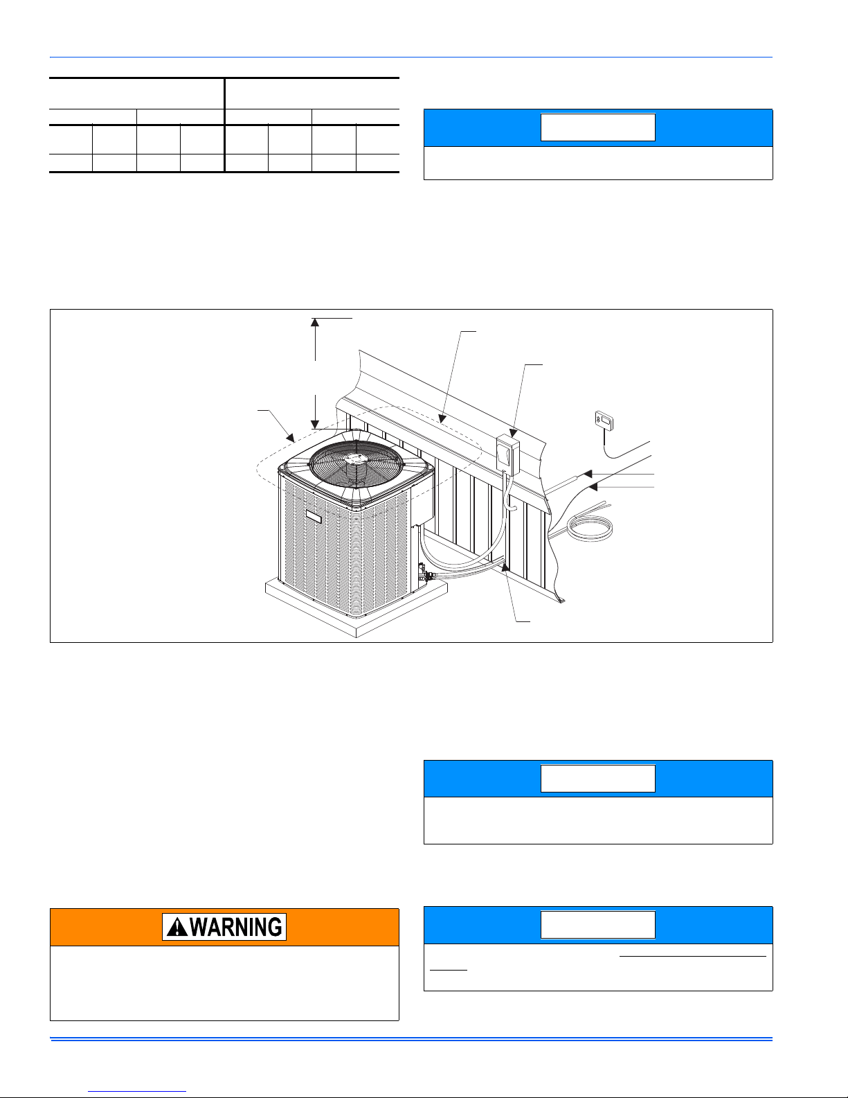
60" OVERHEAD
CLEARANCE
NOTE: ALL OUTDOOR WIRING
MUST BE WEATHERPROOF
TO INDOOR COIL
THERMOSTAT
TO FURNACE OR
AIR HANDLER
TERMINAL BLOCK
MINIMUM 18" SERVICE ACCESS
CLEARANCE ON ONE SIDE
WEATHERPROOF
DISCONNECT
SWITCH
SEAL OPENING(S) WITH
PERMAGUM OR EQUIVALENT
6" CLEARANCE
COIL AREA
NEC CLASS 1 WIRING
NEC CLASS 2 WIRING
NOTICE
NOTICE
AIR TEMPERATURE AT
OUTDOOR COIL, °F
Min. Max. Min. Max.
DB
Cool
50 -10 115 75 57
1. Operation below this temperature is permissible for a short period of time,
2. The maximum allowable line length for this product is 75 feet.
DB
HeatDBCool
during morning warm-up.
DB
Heat
AIR TEMPERATURE AT
INDOOR COIL, °F
WB
Cool
DB
Heat
50
1
WB
Cool
72 80
DB
Heat
SECTION III: UNIT INSTALLATION
LOCATION
Before starting the installation, select and check the suitability of the
location for both the indoor and outdoor unit. Observe all limitations and
clearance requirements.
The outdoor unit must have sufficient clearance for air entrance to the
condenser coil, for air discharge, and for service access. See Figure 1.
For multiple unit installations, units must be spaced a minimum of 18
inches apart (coil face to coil face).
If the unit is to be installed on a hot sun exposed roof or a black-topped
ground area, the unit should be raised sufficiently above the roof or
ground to avoid taking the accumulated layer of hot air into the outdoor
unit.
Provide an adequate structural support.
FIGURE 1: Typical Installation with Required Clearances
GROUND INSTALLATION
The unit may be installed at ground level on a solid base that will not
shift or settle, causing strain on the refrigerant lines and possible leaks.
Maintain the clearances shown in Figure 1 and install the unit in a level
position.
Normal operating sound levels may be objectionable if the unit is placed
directly under windows of certain rooms (bedrooms, study, etc.).
Condensate will drain from beneath the coil of the outdoor unit during
the defrost cycle. Normally this condensate may be allowed to drain
directly on the ground.
Elevate the unit sufficiently to prevent any blockage of the air entrances
by snow in areas where there will be snow accumulation. Check the
local weather bureau for the expected snow accumulation in your area.
Isolate the unit from rain gutters to avoid any possible wash out of the
foundation.
The outdoor unit should not be installed in an area where mud or ice
could cause personal injury. Remember that condensate will drip
from the unit coil during heat and defrost cycles and that this condensate will freeze when the temperature of the outdoor air is below
32°F.
UNIT PLACEMENT
1. Provide a base in the pre-determined location.
2. Remove the shipping carton and inspect for possible damage.
3. Compressor tie-down bolts should remain tightened.
4. Position the unit on the base provided.
Heat pumps will defrost periodically resulting in water drainage. The
unit should not be located where water drainage may freeze and create a hazardous condition - such as sidewalks and steps.
LIQUID LINE FILTER-DRIER
The heat pumps have a solid core bi-flow filter/drier located on the liquid
line.
Replacements for the liquid line drier must be exactly the same as
marked on the original factory drier. See Source 1 for O.E.M.
replacement driers.
2 Johnson Controls Unitary Products
Page 3

Failure to do so or using a substitute drier or a granular type may
12“
12“
Center Point
NOTICE
result in damage to the equipment.
689103-BIM-B-1012
Filter-Drier
Source 1 Part No.
S1-52636219000 All
*As listed on the “Energy Guide yellow sticker on the unit.
Apply with Models
OUTDOOR THERMOSTATS
(All installations of this heat pump in Manufactured Homes built
per HUD standards SHALL have an outdoor thermostat installed at
the time of installation by the installer. In accordance with HUD
std. 3280.714 (a) (1) (ii). Outdoor thermostat, Part number 30246881/D or equivalent shall be used and should be ordered at your
nearest UPG Parts Source). See last page of these instructions.
Select the proper location for mounting the outdoor thermostat (see
instructions packed with outdoor thermostat).
INDOOR UNITS
Install the indoor coil in the furnace or air handler according to the
installation instructions packed with each component.
REFRIGERANT LINE
Do not remove protective caps from couplings until pre-charged lines
are routed and ready for final connection. Protective caps prevent dirt
from entering couplings and contaminating system when connected
together.
1. Refer to the tabular data sheet for the correct line set kit part number for your unit.
a. Check the size of the pre-charged refrigerant lines to insure that
they are correct for the model being installed.
b. Check the final routing of the tubing, and insure tubing will be of
adequate length, with allowance for connection at the coil and
outdoor unit.
The line set part number, size, and length are shown in the tabular data
sheet. Do not use any line sets other than those shown. Refer to the
appropriate line set Installation Manual.
2. Copper tubing will work-harden (for copper tubing only).
a. The pre-charged tubing should be handled carefully.
b. Do not bend or work the tubing any more than necessary. (The
larger size tubing 3/4" for example, will work-harden rapidly as it
is formed. As the tubing becomes harder, it is more susceptible to
kinking and damage).
3. Forming Copper (for copper tubing only).
a. No attempt should be made to bend the suction line in a shorter
radius than 12". See Figure 2.
FIGURE 2: Minimum Suction Line Form
4. How to dispose of excess tubing.
a. Tubing may be longer than required. Coil excess tubing nearer
the indoor coil rather than the outdoor unit.
b. Excess tubing must be coiled horizontally so the flow of refriger-
ant is from top to bottom of the coil and toward the outdoor unit.
Another method is to form a horizontal “U” large enough to take
care of excess. See Figure 3.
FIGURE 3: Excess Tubing
5. Slope tubing toward outdoor unit.
a. When the coil is above the outdoor unit, the suction line should be
sloped with a fall of a least 1/4" per foot toward the outdoor unit.
b. When the outdoor unit is above the coil, the tubing should be
sloped downward along lateral distance to the bottom, or from the
vertical riser.
6. Insulation of suction line.
a. Standard suction lines come pre-insulated from the factory with 3/
8" closed cell insulation, adequate for average installations.
In regions of extreme temperatures and humidity, additional insulation may be required to prevent excessive condensation and serious
loss of capacity.
b. Do not insulate liquid and suction lines together.
c. Liquid lines should not be insulated.
d. Liquid lines should not be in bare contact with suction line. See
Figure 4.
Johnson Controls Unitary Products 3
Page 4

689103-BIM-B-1012
Liquid
Line
Incorrect
Correct
Tape
Sheet Metal Hanger
Insulated Vapor Line
FIRST CONNECTION
TO INDOOR COIL
SECOND CONNECTION
TO OUTDOOR COIL
INSULATION
TIGHTEN
BACK UP
BACK UP
TIGHTEN
FIGURE 4: Insulation of Vapor Line
Liquid refrigerant under pressure. Liquid refrigerant can cause
severe frostbite. To avoid possible loss of sight and/or frostbite use
eye protection (safety glasses or safety face shield). Wearing leather
gloves will offer protection to hands.
7. Install refrigerant lines to indoor coil first. The couplings without
Schrader Valves are to be connected to the indoor coil. See Figure
5.
a. Form the tubing so it is properly aligned with the connections on
the coil.
b. Remove plugs and caps from connections.
c. Check that the rubber seals in connection ends are intact.
d. Be sure surfaces are clean.
e. Lubricate the rubber seals with clean POE oil and make connec-
tions.
f. Thread couplings together by hand to be sure they are not cross
threaded. Tighten coupling so diaphragms are touching (do not
puncture diaphragms at this time).
FIGURE 6: Quick Connect Coupling Connections
9. Tightening couplings (for Flexi Fit & Copper only).
a. Tighten indoor coil couplings with wrenches; using wrench on sta-
tionary fitting of coupling and liquid line fitting at coil while nut is
being tightened. See Figure 6. Tighten the nut until the coupling
bottoms out.
b. Then tighten an additional 1/6 turn to complete the knife edge
seal.
c. Tighten outdoor unit couplings, with wrenches using a wrench on
the stationary fitting of the coupling while nut is being tightened.
Tighten the nut until the coupling bottoms out.
d. Then tighten an additional 1/6 turn to complete the knife edge
seal.
10.Check for leaks.
a. After the line set connections have been made they should be
checked for leaks.
b. If the valves were kept clean and lubricated per instruction no
leaks should be found.
c. Use leak detect solution or soap solution for leak testing. An elec-
tronic leak detector is recommended.
FIGURE 5: Typical Quick Connect Refrigerant Line Set
8. Install refrigerant line to outdoor unit. The couplings with Schrader
Valves are to be connected to the outdoor unit.
a. Form the tubing so it is properly aligned with the connections on
the outdoor unit. Insure the Schrader Valves are accessible.
b. Check that the rubber seals in connection ends are intact.
c. Be sure surfaces are clean.
d. Lubricate the rubber seals with clean POE oil and make connec-
tions.
e. Thread couplings together by hand to be sure they are not cross
threaded. Tighten coupling so diaphragms are touching (do not
puncture diaphragms at this time).
4 Johnson Controls Unitary Products
IT IS UNLAWFUL TO KNOWINGLY VENT, RELEASE OR DISCHARGE REFRIGERANT INTO THE OPEN AIR DURING REPAIR,
SERVICE, MAINTENANCE OR THE FINAL DISPOSAL OF THIS
UNIT.
WHEN THE SYSTEM IS FUNCTIONING PROPERLY AND THE
OWNER HAS BEEN FULLY INSTRUCTED, SECURE THE
OWNER’S APPROVAL.
REFRIGERANT LINE SUPPORT
Refrigerant lines should be supported in a way that no dips or sags
occur. We recommend four feet between supports. If refrigerant lines
are to be attached to the home structure, care should be taken to eliminate the transmission of vibrations. Attach the refrigerant lines to the
indoor coil first. Remove plugs from the indoor coil, then clean joints to
be brazed. Braze refrigerant lines to the indoor coil. Attach refrigerant
lines to the outdoor unit.
CHARGING AND LEAK TESTING
On systems with or without service valves the refrigerant should be
recovered or recycled in accordance with EPA regulations. In some
cases this may require putting piercing valves on both the high and low
sides of the system.
Page 5

DO NOT vent refrigerant to the outdoors.
Start
Relay
(Optional)
Defrost
Control
Board
Start Capacitor
(Optional)
Ground
Lug
“Fingered”
Bushing
Low
Voltage
Box
Reversible High
Voltage Conduit Plate
Contactor
Dual
Run/Fan
Capacitor
NOTICE
NOTICE
Y
O
R
L
X
W2
G
Y
O
R
X/L
C
W
YEL
ORG
RED
PUR
BLK
BRN
WHT
WALL
THERMOSTAT
YEL (NOT USED)
YEL (NOT USED)
MANUFACTURED HOUSING
ELECTRIC FURNACE
WITH 4 WIRE CONTROL BOX
TYPICAL MANUFACTURED HOUSING INSTALLATION
W / SINGLE STAGE OUTDOOR THERMOSTAT 3024-6881/D
E
G
R
C
W
WHT
GRN
WHT
BLK
RED
+
2
4
5
1
2
+
Confirm that wire is connected
to terminal 2, not terminal 5.
If not, then move wire from
terminal 5 to terminal 2.
W1/66
SINGLE-STAGE OUTDOOR THERMOSTAT
HEAT
PUMP
When recovering refrigerant from a system, with a burnout, follow a
safe procedure due to possible contamination.
Avoid getting the refrigerant in the eyes or on the skin.
Contaminated refrigerant must be recovered and returned to the local
refrigeration supply house for proper disposition.
SECTION IV: ELECTRICAL CONNECTIONS
GENERAL INFORMATION & GROUNDING
Check the electrical supply to be sure that it meets the values specified
on the unit nameplate and wiring label.
Power wiring, control (low voltage) wiring, disconnect switches and over
current protection must be supplied by the installer. Wire size should be
sized per NEC requirements.
All field wiring must USE COPPER CONDUCTORS ONLY and be in
accordance with Local, National, Fire, Safety & Electrical Codes.
This unit must be grounded with a separate ground wire in accordance with the above codes.
The complete connection diagram and schematic wiring label is located
on the inside surface of the unit service access panel.
FIELD CONNECTIONS POWER WIRING
1. Install the proper size weatherproof disconnect switch outdoors and
within sight of the unit.
2. Remove th e screws from the control box cover and remove from
unit.
3. Run power wiring from the disconnect switch to the unit.
4. Route wires from disconnect through power wiring opening provided
and into the unit control box as shown in Figure 7.
5. Install the proper size time-delay fuses or circuit breaker, and make
the power supply connections.
689103-BIM-B-1012
FIGURE 7: Outdoor Unit Control Box
FIELD CONNECTIONS CONTROL WIRING
1. Route low voltage wiring into bottom of control box as shown in Figure 7. Make low voltage wiring connections inside the low voltage
box per Figure 8.
2. The complete connection diagram and schematic wiring label is
located on the inside surface of the unit service access panel.
3. Replace the control box cover removed in Step 2.
4. All field wiring to be in accordance with national electrical codes
(NEC) and/or local-city codes.
5. Mount the thermostat about 5 feet above the floor, where it will be
exposed to normal room air circulation. Do not place it on an outside
wall or where it is exposed to the radiant effect from exposed glass
or appliances, drafts from outside doors or supply air grilles.
6. Route the 24-volt control wiring (NEC Class 2) from the outdoor unit
to the indoor unit and thermostat.
To eliminate erratic operation, seal the hole in the wall at the thermostat with permagum or equivalent to prevent air drafts affecting the
operation of in the thermostat.
FIGURE 8: Typical Wiring with Thermostat and Furnace / Air Handler
Johnson Controls Unitary Products 5
A Start Assist Kit is available and recommended for long line set
applications or in areas of known low voltage problems.
Page 6

689103-BIM-B-1012
TEST
AMBIENT
AMBG
COIL G
COIL
1
2
3
4
COND
FAN
HIGH VOLTAGE
PRESSURE
M
SWITCH
REV
VALVE
X/L
R
C
Y
O
W
W1/66
X/L
R
C
Y
O
W
W1/66
DEMAND
DEFROST CURVE
SELECTION JUMPER
P
SECTION V: SYSTEM OPERATION
ANTI-SHORT CYCLE DELAY
The control includes a five-minute anti-short cycle delay (ASCD) timer
to prevent the compressor from short cycling after a power or thermostat signal interruption. The ASCD timer is applied when the control is
first powered from the indoor unit thermostat and immediately following
the completion of a compressor run cycle. The compressor and the out-
TEST INPUT
The control includes a TEST input connector that can be used for various testing functions during installation and service. The TEST input
connector is shown in Figure 9. The following table summarizes the
behavior of the control when the two TEST pins are connected. More
detailed descriptions of the various functions are included in other sections of this document.
door fan will not operate during the five minutes that the timer is active.
The ASCD timer can be bypassed by connecting the TEST terminals
for three seconds while the thermostat is calling for compressor operation (Y input signal energized).
LOW VOLTAGE DETECTION
The control monitors the transformer secondary (24 VAC) voltage and
provides low voltage protection for the heat pump and its components.
In particular, the control prevents contactor chatter during low voltage
conditions. If the voltage drops below approximately 19 VAC, the control will continue to energize any relays that are already energized but
will not energize any additional relays until the voltage level increases.
If the voltage drops below approximately 16 VAC, the control will immediately de-energize the relay outputs and will not energize any relays
until the voltage level increases.
FIGURE 9: Demand Defrost Control Module
TABLE 1:
TEST Input Functionality
Duration of connection (seconds) Control behavior
Less than 2 No response
2-6
Bypass ASCD. If Y is present and pressure switch is
closed, contactors will be energized.
Clear lockout
More than 6
Initiate defrost cycle ignoring the liquid line and outdoor ambient temp.
Energize X/L with active defrost curve flash code
Connection removed Terminate defrost as normal.
Connection not removed Continue defrost cycle and X/L flash code until TEST connection removed.
FAULT CODE DISPLAY
X/L Output
The X/L terminal of the heat pump control is typically connected to the
X/L input of the room thermostat. The thermostat uses this signal to
notify the homeowner of a problem with the heat pump using an LED or
LCD display. When the control energizes the X/L terminal, the thermostat displays the flash code so the homeowner can see it.
TABLE 2:
Condition X/L
Pressure Switch lockout - last mode of operation was heating 2 flashes
Pressure Switch lockout - last mode of operation was defrost 3 flashes
When the control locks out the compressor because of a pressure
switch lockout, it will energize the X/L output as shown in Table 2. The
control has a three second delay between fault code flashes.
DEFROST OPERATION
General
The control maintains proper airflow through the outdoor coil during
heating operation by melting frost and ice that may form on the coil.
Frost may accumulate unevenly in different sections of the coil because
of the arrangement of the refrigeration circuit within the coil. The control
may initiate a defrost cycle even when the coil is not completely covered with frost. This is normal operation.
6 Johnson Controls Unitary Products
X/L Output Categories
The control regulates the defrost operation of the heat pump.
• Defrost is based on accumulated compressor run time, outdoor
coil temperature, and outdoor ambient temperature.
The control will cause the unit to operate in the normal heating mode
until it determines that a defrost cycle is needed.
All defrost timings are based on accumulated compressor run time.
Operation
The defrost mode is equivalent to the cooling mode except that the outdoor fan motor is de-energized. The control shall do the following to initiate a defrost cycle.
• De-energize the outdoor fan
• Energize the reversing valve
• Energize the auxiliary heat output through the W1/66 terminal.
• Begin the maximum defrost cycle length timer
If the call for heating (Y) is removed from the control during the defrost
cycle, it will terminate the defrost cycle and de-energize the compressor. The control will also stop the defrost cycle length timer but not reset
it. When the control receives another call for heating, it will restart the
defrost cycle and the timer at the point at which the call for heating was
removed. This will happen only if the liquid line temperature conditions
allow defrost to occur.
Page 7

689103-BIM-B-1012
Defrost Curves
The control uses a set of defrost curve parameters that are selected
using the defrost curve selection jumper. The location of the defrost
curve selection jumper is shown in Figures 10. Table 3 shows the
jumper position that is appropriate for each heat pump model. Jumper
position 4 is not used and the control will not allow the compressor to
operate when the jumper is in this position.
Defrost Curve Selection
The factory activates the correct defrost curve during production. They
will place the defrost curve selection jumper in the P position or in a
numbered position appropriate for the specific heat pump model. You
should not have to change the defrost curve selection jumper during initial installation.
If the jumper is inadvertently moved, it should be placed in the appropriate numbered location based on the model number and Table 3. If the
factory has activated the curve using the P position, the jumper may
also be returned to that position. If, however, the factory has not activated the curve in the P position and the jumper is placed in the P position, the control will not energize the compressor. The control will also
not energize the compressor if the defrost curve selection jumper is in a
numbered position that is not described in Table 3 or if the defrost curve
selection jumper is missing. The control will display the proper fault
code when a defrost curve jumper error is present. If the jumper is missing, the control will behave as if the jumper was in the P position. If the
jumper is placed in a numbered position, the defrost curve selected by
the jumper will override the defrost curve activated at the factory until
the jumper is returned to the P position. The control will display the
active defrost curve using the X/L terminal when the heat pump is operating in a defrost cycle that has been forced using the TEST inputs.
It will also display the active defrost curve using the X/L terminal when
the operational mode is being displayed using the LED’s. For instance,
the X/L output will be energized with two flashes when defrost curve 2 is
active. The control only reads the jumper input when the Y and W thermostat inputs are de-energized. If a jumper position is changed while
either of these inputs is energized, the control will not act upon the
jumper changes until the thermostat calls are de-energized or power
(24 VAC) to the control is cycled.
Defrost Cycle Initiation
The control will allow the heat pump to operate in the heating mode until
the combination of outdoor ambient and outdoor coil temperatures indicate that a defrost cycle is necessary.
The control will initiate a defrost cycle when the liquid line temperature
is below the initiate point for the measured ambient temperature (See
Figure 10) continuously for 4-1/2 minutes. This delay eliminates unnecessary defrost cycles caused by refrigeration surges such as those that
occur at the start of a heating cycle.
The control will initiate a defrost cycle every 6 hours (accumulated compressor run time) to recirculate refrigerant lubricants. This forced
defrost timer will be reset and restarted following the completion or termination of a defrost cycle.
The control will also initiate a defrost cycle when the TEST terminals
are shorted. This feature allows an installer or service technician to start
a defrost cycle immediately as required. When the TEST terminals are
shorted for more than six seconds with a Y input energized and the
pressure switch input is closed, the ASCD will be bypassed and the
compressor and the W1/66 terminal to auxiliary heat will be energized.
When the TEST inputs are used to force a defrost cycle, the control will
ignore the state of the liquid line temperature and outdoor ambient temperature inputs. The coil does not have to be cold and the outdoor temperature does not have to be within a certain range for the heat pump to
be forced into a defrost cycle. After the TEST input jumper is removed,
the defrost mode will be terminated as normal. The defrost cycle length
timer will not be started until the TEST input is removed. If the TEST terminals remain shorted, the control will keep the unit in defrost mode.
Defrost Inhibition
The control will not initiate a defrost cycle if the liquid line temperature is
above 40F unless the defrost cycle is forced using the TEST input.
The control will not initiate a defrost cycle when the outdoor ambient
temperature is below –25F or above 55F unless the defrost cycle is
forced using the TEST input.
The control will also prevent a defrost cycle from being initiated too
soon after the initiation of the previous defrost cycle. When power is
applied to the control and after the completion or termination of each
defrost cycle, the control will start a 40-minute timer. When this timer
expires, the control will allow another defrost cycle when needed. The
timer is based on accumulated compressor run time.
Defrost Termination
The control will terminate the defrost cycle immediately after the liquid
line temperature reaches 80F or after eight minutes of defrost operation.
The control will do the following to terminate a defrost cycle.
• Energize the outdoor fan
• De-energize the reversing valve
• De-energize the auxiliary heat output through the W1/66 terminal
• Reset and restart the 40-minute defrost inhibit timer
TABLE 3:
Defrost Curve Selection Jumper Position1234
All Units All None None None
Defrost Initiate Curves
Johnson Controls Unitary Products 7
Page 8

689103-BIM-B-1012
REGION C
TERMINATE CURVE
INHIBIT CURVE
INITIATE CURVE
REGION A
REGION B
REGION D
REGION E
AMBIENT TEMPERATURE
LIQUID LINE (COIL) TEMPERATURE
Defrost prevented from starting
No call for defrost
Time Defrost (6 hour) prevented
No call for Defrost
Time Defrost (6 hour) allowed
Call for Defrost
Defrost Terminated
FIGURE 10: Defrost Operation Curves
COOLING OPERATION
During cooling operation, the control will receive thermostat signals at
the Y and O input terminals. The control will energize the M compressor
output terminal. This signal energizes the coil of the compressor contactor causing the compressor to run. The control also delivers power to
the COND FAN terminals causing the outdoor fan to operate. The control energizes the REV VALVE terminal with 24VAC to switch the
reversing valve.
HEATING OPERATION
During normal heating mode, the control will receive a thermostat signal
at the Y input terminal. The control will energize the M compressor output terminal. This signal energizes the coil of the compressor contactor
causing the compressor to run. The control also delivers power to the
COND FAN terminals causing the outdoor fan to operate. The reversing
valve is not energized in heating mode.
EMERGENCY HEAT
When the thermostat calls for emergency heat operation (W signal without a Y signal), the control will de-energize the compressor and energize the W1/66 terminal immediately.
PRESSURE SWITCH FAULT & LOCKOUT
The heat pump is equipped with a pressure switch and an optional low
pressure switch that are connected to the control at the pressure switch
terminals. If the pressure switch input opens for more than 40 milliseconds, the control will de-energize the compressor. If the pressure switch
closes and a thermostat call for compressor operation is present, the
control will apply the five-minute anti-short cycle delay timer and start
the compressor when the timer expires.
When the compressor is started following a pressure switch fault, the
control will start a six-hour timer based on accumulated compressor run
time. If the control senses another opening of the pressure switch
before the timer expires, it will cause a soft lockout condition. The second opening of the pressure switch must be greater than 160 milliseconds for the lockout to occur. If the second opening is between 40 and
160 milliseconds, the control will de-energize the compressor but not
cause a soft lockout condition. If the control does not sense a second
pressure switch opening before the six-hour timer expires, the timer and
counter will be reset.
During the soft lockout mode, the control will de-energize the compressor and energize the X/L output with the appropriate flash code.
The control will reset the soft lockout condition when any of the following occur following removal of the fault condition.
1. Power is cycled to the R or Y inputs of the control. This will cause
the soft lockout condition to be reset when the thermostat is satisfied or when the thermostat is set to SYSTEM OFF and back to
HEAT or COOL mode.
2. The TEST terminals are shorted for more than two seconds.
When the soft lockout condition is reset, the control will stop displaying
the fault code and will respond to thermostat inputs normally.
8 Johnson Controls Unitary Products
Page 9

FIGURE 11: Heat Pump Flow Diagram
CHARGE COMPENSATOR
(Empty in cooling / full in heating)
(Not included in all Units)
FIELD
CONNECTED LINE
INDOOR COIL
OUTDOOR
COIL
4-WAY
REVERSING
VALV E
FILTER DRYER
(Solid core)
SUCTION
ACCUMULATOR
LIQUID
SENSOR
COMPRESSOR
FIELD CONNECTED LINE
SHOWN IN COOLING POSITION.
COOLING CYCLE FLOW
HEATING CYCLE FLOW
BI-FLOW
TXV/CHECK
VALVE (Cooling) **
** NOTE: The indoor coil is shipped
with an orifice. The orifice must be
replaced with a TXV Kit.
BI-FLOW TXV/CHECK
VALVE OR ORIFICE (Heating)
LOW PRESSURE SWITCH
HIGH
PRESSURE
SWITCH
689103-BIM-B-1012
SECTION VI: INSTRUCTING THE OWNER
Assist owner with processing warranty cards and/or online registration.
Review Owners Guide and provide a copy to the owner and guidance
on proper operation and maintenance. Instruct the owner or the operator how to start, stop and adjust temperature setting.
When applicable, instruct the owner that the compressor is equipped
with a crankcase heater to prevent the migration of refrigerant to the
compressor during the “OFF” cycle. The heater is energized only when
the unit is not running. If the main switch is disconnected for long periods of shut down, do not attempt to start the unit until 8 hours after the
switch has been connected. This will allow sufficient time for all liquid
refrigerant to be driven out of the compressor.
The installer should also instruct the owner on proper operation and
maintenance of all other system components.
MAINTENANCE
1. Dirt should not be allowed to accumulate on the outdoor coils or
other parts in the air circuit. Clean as often as necessary to keep the
unit clean. Use a brush, vacuum cleaner attachment, or other suitable means.
2. The outdoor fan motor is permanently lubricated and does not
require periodic oiling.
3. If the coil n eeds to be cleaned, it should be washed with Calgon
Coilclean (mix one part Coilclean to seven parts water). Allow solution to remain on coil for 30 minutes before rinsing with clean water.
Solution should not be permitted to come in contact with painted
surfaces.
4. Refer to the furnace or air handler instructions for filter and blower
motor maintenance.
5. The ind oor coil a nd dra in pan should be inspected and cleaned regularly to prevent odors and assure proper drainage.
Johnson Controls Unitary Products 9
Page 10

SECTION VII: WIRING DIAGRAM
FIGURE 12: Wiring Diagram
Subject to change without notice. Published in U.S.A. 689103-BIM-B-1012
Copyright © 2012 by Johnson Controls, Inc. All rights reserved. Supersedes: 689103-BIM-A-0412
York International Corp.
3110 N Mead
Wichita, KS 67219
 Loading...