

Page 1
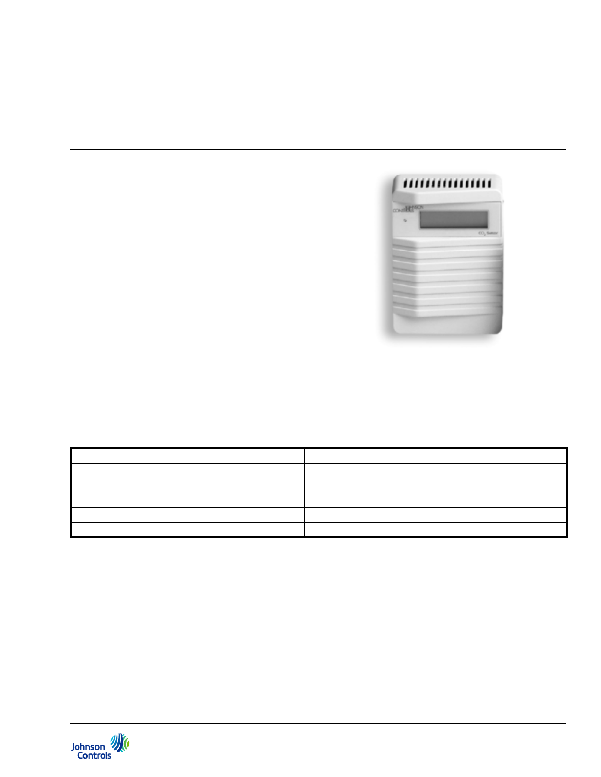
Figure 1: Wall Mount CO2 Transmitter with
Display
CD-Wxx-00-0 Series Wall Mount CO2 Transmitter
Product Bulletin
CD-Wxx-00-0
Refer to the QuickLIT Web site for the most up-to-date version of this document.
Johnson Controls offers a full line of Carbon Dioxide
(CO
) transmitters for measuring and transmitting CO2
2
levels, ranging from 0 to 2,000 parts per million (ppm),
within Heating, Ventilating, and Air Conditioni ng
(HVAC) CO
applications include Demand Control Ventilation
(DCV), fresh air and Indoor Air Quality (IAQ), and
rooftop air handling Economizer controls systems.
These compact, wall mounted devices output 0 to 10 V
(default), 0 to 20 mA, or 4 to 20 mA signals and feature
analog temperature outputs, relay outputs, and/or a
digital display as (optional) features. They are designed
to work:
• in standalone mode
applications. Specific HVAC CO2
2
Code No. LIT-216527
Supersedes June 1, 2001
Issued July 14, 2011
• connected to Metasys® system
• as part of any integrated Building Automation
System (BAS)
These new CO
transmitters are easy to install, offer a
2
full three year warranty, and require no maintenance or
field calibration.
Table 1: Features and Benefits
Features Benefits
Energy Savings from DCV Strategies Offer potential for 10 to 70% energy savings.
CARBOCAP® Single-Beam, Dual-Wavelength Design Provides superior performance compared to other technologies.
CARBOCAP Silicon, Micro-machined Construction Provides reliable CO
Calibration Reliability Offers 5 years of reliable calibration.
Stable Infrared Reference Compensates for light-source drift.
measurement in room environments.
2
CD-Wxx-00-0 Series Wall Mount CO2 Transmitter Product Bulletin 1
Page 2

Product Overview
This transmitter uses a completely new CO2 sensing
technology. The silicon based CARBOCAP® sensor
provides stability and reliability.
The CARBOCAP sensor operates in accordance with
the single beam, dual wavelength method. This
patented sensor has unique reference measurement
capabilities, offering excellent stability over both time
and temperature. The monolithic Fabry-Perot
Interferometer (FPI) chip uses the optical, mechanical,
and electronic properties of silicon at the same time.
The transmitter is factory set to measure CO
to 2,000 ppm. It requires a Class 2, 24 VDC/V AC power
source and generates an output signal proportional to
the CO
level detected. One simple wire to a screw
2
terminal and a jumper on the Printed Circuit Board
(PCB) combine to select the analog output signal from
the following options:
• 0 to 20 mA
• 4 to 20 mA
• 0 to 10 V (default)
IMPORTANT: The CD-Wxx-00-0 CO
is intended to provide an input to equipment under
normal operating conditions. Where failure or
malfunction of the transmitter could lead to personal
injury or property damage to the controlled
equipment or other property, additional precautions
must be designed into the control system.
Incorporate and maintain other devices, such as
supervisory or alarm systems or safety or limit
controls, intended to warn of or protect against
failure or malfunction of the transmitter.
levels up
2
Transmitter
2
Calibration
Johnson Controls® CO2 transmitters are calibrated
using certified gases for the following:
• output signal (0 to 10 V) proportional to CO
2
concentration (0 to 2,000 ppm)
• altitude range of 0 to 2,000 ft (0 to 600 m) above
sea level without compensation
• relay output trigger point set for 1,000 ppm (in
models featuring the optional relay output)
CARBOCAP Technology
Johnson Controls is licensed to integrate the new,
silicon based CARBOCAP CO
sensor into HVAC or
2
Building Automation Systems. This sensor has several
advantages: high accuracy, excellent stability,
negligible temperature dependence, and ease of
installation.
The structure of the diffusion aspirated, single-beam
dual-wavelength sensor is remarkably simple. It
consists of an Infrared (IR) source, a sample cell, a
tunable interference filter, and an IR detector. The
tunable interference filter enables measurements at
two wavelengths. As a result, references are measured
accurately, without the typically broad tolerances
inherent in dual-beam sensors.
Dust, water vapor, and most chemicals do not affect
the measurement accuracy of the sensor. No special
software compensation patches are required, and the
device requires no maintenance.
Versatile Transmitter
Designed for use with a standard U.S. wallbox or
mounting directly to a wallboard surface, the CO
transmitter generates considerable savings in
installation, operation, and maintenance with no
recalibration costs. Johnson Controls includes a
Drywall Spring-Clip Mounting Kit with each unit.
2
CD-Wxx-00-0 Series Wall Mount CO2 Transmitter Product Bulletin2
Page 3

Energy Efficiency
Figure 2: Cover Dimensions, in. (mm)
Figure 3: Wall Mount Base Dimensions, in. (mm)
Johnson Controls® CO2 transmitters, when used with
BAS/Economizer controllers (featuring DCV
strategies), can generate energy savings ranging up to:
• 20 to 40% in office buildings
• 20 to 60% in restaurants/light retail facilities
• 10 to 70% in educational/business settings
Optional Features
Analog Temperature Module
For applications requiring measurements and outputs
for both CO
transmitter. Th is model includes an analog temperature
module that plugs into the main PCB and has an active
temperature output, linear from 0 to 10 VDC for
32 to 122
and temperature, order the CD-W A0-00-0
2
°F (0 to 50°C).
Dimensions
See Figure 2 and Figure 3 for CO2 transmitter and
mounting flange dimensions.
Relay Module
Order the CD-WR0-00-0 transmitter for applications
where On/Off ventilation or fan control is required to
provide fresh air. This model includes a relay output
module that plugs into the main PCB offering a 30 V,
0.5A Class 2 output with configurable On and Off trip
points. Default On is 1,000 ppm, and default Off is
950 ppm.
Note: To redefine the relay On and Off trip points to
suit the application, use the ACC-CD-S Relay Setpoint
Software.
Relay and Display Module
For applications where the display of the measured
CO
level and a relay output and relay On notification
2
are required, order the CD-WRD-00-0. This module
contains a relay and a digital display. The unit plugs
into the transmitter PCB. The display includes a 4-digit
display and a Light-Emitting Diode (LED), which
indicates when the relay is On.
Note: To redefine the relay On and Off trip points to
suit the application, use the ACC-CD-S Relay Setpoint
Software.
Repair Information
If the CD-Wxx-00-0 Series Wall Mount Tr ansmitter fails
to operate within its specifications, replace the unit. For
a replacement CO
Johnson Controls representative.
transmitter, contact the nearest
2
Altitude Compensation
These devices are intended for an altitude range of
0 to 2,000 ft (0 to 600 m) without compensation. To
compensate for higher altitudes, refer to the installation
instructions for this device.
CD-Wxx-00-0 Series Wall Mount CO2 Transmitter Product Bulletin3
Page 4

Ordering Information
Contact the nearest Johnson Controls representative to
order a CO
product code number from Table 2. See Table 3 for
replacement parts and Table 4 for acce sso rie s
available for the duct mount CO
Table 2: CO2 Wall Mount Transmitters
Product Code Number Description
CD-WA0-00-0
CD-WR0-00-0
CD-WRD-00-0
Table 3: Replacement Parts for Wall Mount CO2 Transmitters
Product Code Number Description
ACC-DWCLIP-0 Drywall Spring-Clip Mounting Kit
ACC-CD-R Relay Output Module for CD-WR0-00-0
Table 4: Accessories for Wall Mount CO2 Transmitters
Product Code Number Description
ACC-CD-S Relay Setpoint Software Kit; includes software and interface cable to reset
Y65T31-0 Multiple Primary Transformer, 40 VA, 102/208/240 V Primary 24 V Class 2
transmitter, and specify the desired
2
transmitter.
2
Transmitter with Analog Temperature Output
Transmitter with Relay
Transmitter with Relay and Display
the On and Off relay setpoints for CD-WR0-00-0 and CD-WRD-00-0
Secondary with Screw Terminals, Foot Mounting or 4 x 4 in.
(101.6 x 101.6 mm) Plate
Technical Specifications
CD-Wxx-00-0 Wall Mount CO2 Transmitter (Part 1 of 2)
Measuring Range 0 to 2,000 ppm CO
CO2 Accuracy at 77°F (25°C) ±(40 ppm CO2 + 2.0% of reading) (includes manufacturing deviation and drift). All
accuracy specifications reflect the testing of transmitters using high-grade,
certified gases. Transmitters are intended for an altitude range of 0 to 2 ,000 ft
(0 to 600 m) above sea level without compensation.
Non-Linearity <1.0% of Full Scale (FS)
CO
2
Temperature Dependence of CO
Output
Long-Term CO
Response Time (0 to 63%) 1 Minute
CO
2
Operating Temperature Range 23 to 113°F (-5 to 45°C)
Storage Temperature Range -4 to 158°F (-20 to 70°C)
Humidity Range 0 to 85% RH (noncondensing)
Transmitter Output Signals
CO
2
Relay Contact Rati ngs (Optional) 30 V, 0.5 A Class 2
Analog Temperature Module
(Optional)
Stability ±5% of Full Scale/5 Years
2
2
<0.083% of Full Scale/F°(<0.15% of Full Scale/C°)
Jumper Selectable: 0 to 20 mA and 4 to 20 mA or 0 to 10 VDC (Default)
Maximum Output Current: 25 mA; Maximum Output Voltage: 12.5 V
Linear 0 to 10 VDC for 32 to 122°F (0 to 50°C)
2
CD-Wxx-00-0 Series Wall Mount CO2 Transmitter Product Bulletin4
Page 5

Metasys® and Johnson Controls® are registered trademarks of Johnson Controls, Inc.
All other marks herein are the marks of their respective owners. © 2011 Johnson Controls, Inc.
Building Efficiency
507 E. Michigan Street, Milwaukee, WI 53202
CD-Wxx-00-0 Wall Mount CO2 Transmitter (Part 2 of 2)
Resolution of CO2 Display 10 ppm
Recommended External Load (CO
Power Supply Range 20 to 30 VAC (18 to 30 VDC), Class 2
Power Consumption <2.5 W Average, 4.1 VA
Warm-Up Time 1 Minute, 15 Minutes for Full for CO
Dimensions (H x W x D) 3-5/32 x 4-9/32 x 1-3/8 in. (80 x 108.5 x 35 mm)
Shipping Weight 3.5 oz. (100 g)
Compliance United States UL Listed, File E27734, CCN XAPX
Canada UL Listed, File E27734, CCN XAPX7
Europe CE Mark – Johnson Controls, Inc., declares that this product is in compliance with
The performance specifications are nominal and conform to acceptable industry standards. For application at conditions beyond these
specifications, consult the local Johnson Controls office. Johnson Controls, Inc. shall not be liable for damages resulting from misapplication or
misuse of its products.
United States Emissions Compliance
This equipment has been tested and found to comply with the limits for a Class A digital device pursuant to Part 15 of the FCC Rules. These
limits are designed to provide reasonable protection against harmful interference when this equipment is operated in a commercial
environment. This equipment generates, uses, and can radiate radio frequency energy and, if not installed and used in accordance with the
instruction manual, may cause harmful interference to radio communications. Operation of this equipment in a residential area is likely to cause
harmful interference, in which case the user will be required to correct the interference at his/her own expense.
) Current Output: Maximum 500 ohm Load Resistance
2
Voltage Output: Minimum 1,000 ohm Load Resistance
Specification, 30 Minutes for Temperature
2
Measurement
FCC Compliant to CFR47, Part 15, Subpart B, Class A
Industry Canada Compliant, ICES-003
the essential requirements and other relevant provisions of the
EMC Directive 2004/108/EC.
Canadian Emissions Compliance
This Class (A) digital apparatus meets all the requirements of the Canadian Interference-Causing Equipment Regulations.
Cet appareil numérique de la Classe (A) respecte toutes les exigences du Règlement sur le matériel brouilleur du Canada.
CD-Wxx-00-0 Series Wall Mount CO2 Transmitter Product Bulletin 5
Published in U.S.A. www.johnsoncontrols.com
 Loading...