

Page 1
24-10864-11, Rev. B
!
CD-W00-x0-2 Series Wall Mount CO2 and Temperature
Transmitters
Installation Instructions
CD-W00-00-2, CD-W00-N0-2
Refer to the QuickLIT website for the most up-to-date version of this document.
Part No. 24-10864-11, Rev. B
Issued March 2016
North American Emissions Compliance
United States
This equipment has been tested and found to comply with
the limits for a Class A digital device pursuant to Part 15 of
the FCC Rules. These limits are designed to provide
reasonable protection against harmful interference when
this equipment is operated in a commercial environment.
This equipment generates, uses, and can radiate radio
frequency energy and, if not installed and used in
accordance with the instruction manual, may cause
harmful interference to radio communications. Operation
of this equipment in a residential area may cause harmful
interference, in which case users will be required to
correct the interference at their own expense.
Canada
This Class (A) digital apparatus meets all the
requirements of the Canadian Interference-Causing
Equipment Regulations.
Cet appareil numérique de la Classe (A) respecte toutes
les exigences du Règlement sur le matériel brouilleur du
Canada.
Installation
IMPORTANT: The CD-W00-x0-2 Series Wall Mount CO2
and Temperature Transmitters are intended to provide
an input to equipment under normal operating conditions.
Where failure or malfunction of the transmitter could lead
to personal injury or property damage to the controlled
equipment or other property, additional precautions must
be designed into the control system. Incorporate and
maintain other devices, such as supervisory or alarm
systems or safety or limit controls, intended to warn of or
protect against failure or malfunction of the transmitter.
IMPORTANT : Le CD-W00-x0-2 Series Wall Mount CO
and Temperature Transmitters est destiné à transmettre
des données entrantes à un équipement dans des
conditions normales de fonctionnement. Lorsqu'une
défaillance ou un dysfonctionnement du CD-W00-x0-2
Series Wall Mount CO2 Transmitters risque de provoquer
des blessures ou d'endommager l'équipement contrôlé ou
un autre équipement, la conception du système de
contrôle doit intégrer des dispositifs de protection
supplémentaires. Veiller dans ce cas à intégrer de façon
permanente d'autres dispositifs, tels que des systèmes de
supervision ou d'alarme, ou des dispositifs de sécurité ou
de limitation, ayant une fonction d'avertissement ou de
protection en cas de défaillance ou de dysfonctionnement
du CD-W00-x0-2 Series Wall Mount CO
Temperature
Transmitters.
and
2
2
CAUTION: Risk of Electric Shock.
Disconnect the power supply before making
electrical connections to avoid electric shock.
MISE EN GARDE : Risque de décharge
électrique.
Débrancher l'alimentation avant de réaliser tout
raccordement électrique afin d'éviter tout risque
de décharge électrique.
CD-W00-x0-2 Series Wall Mount CO2 and Temperature Transmitters
Installation Instructions
1
Page 2
!
CAUTION: Risk of Property Damage.
!
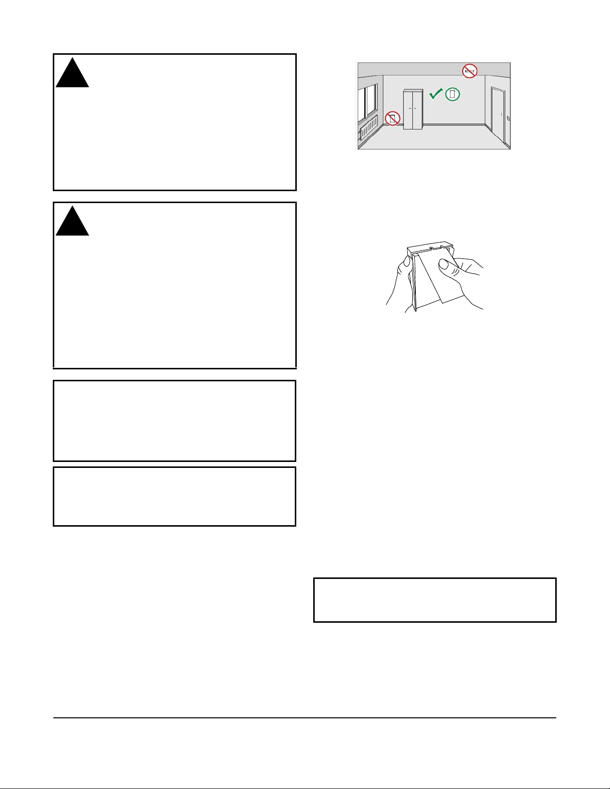
Figure 1: Location Selection
Figure 2: Pull Outward on the Paper Tab
Do not apply power to the system before
checking all wiring connections. Short circuited
or improperly connected wires may result in
permanent damage to the equipment.
MISE EN GARDE : Risque de dégâts
matériels.
Ne pas mettre le système sous tension avant
d'avoir vérifié tous les raccords de câblage. Des
fils formant un court-circuit ou connectés de
façon incorrecte risquent d'endommager
irrémédiablement l'équipement.
CAUTION: Risk of Property Damage.
Do not run low voltage cable in the same conduit
or wiring troughs with high voltage wires.
Running low and high voltage wires in the same
conduit or wiring troughs may damage the
equipment or cause system malfunction.
MISE EN GARDE : Risque de dégâts
matériels.
Ne pas faire courir un câble basse tension dans
les mêmes gaines ou goulottes électriques que
des câbles haute tension. L'installation de fils
basse tension et haute tension dans les mêmes
gaines ou goulottes électriques risque
d'endommager l'équipement ou de provoquer
des dysfonctionnements du système.
IMPORTANT: Use copper conductors only. Make all
wiring in accordance with local, national, and regional
regulations. Do not exceed the CD-W00-x0-2 Series Wall
Mount CO
ratings. Exceeding transmitter electrical ratings can result
in permanent damage to the transmitter and void any
warranty.
IMPORTANT: When using multi-stranded wire cable,
apply a cable ferrule to the cable end. If the distance
between the sensor and the controller is over 3 meters
(9.8 feet), use shielded cable. Connect the shield at the
controller end of the cable.
and Temperature Transmitters electrical
2
Location Selection
When mounting wall model transmitters:
• Select a location that well represents the area of
interest.
• Do not install the transmitter on the ceiling.
• Avoid placing the transmitter near heat and
moisture sources, close to the discharge of the
supply air ducts, and in direct sunlight.
Installing the Mounting Base and Cable
1. Open the transmitter by pulling outward on the
paper tab that holds the cover and mounting base
together (Figure 2).
2. Pull the mounting base away from the cover,
starting from the top.
3. Pull out approximately 6 in. (152 mm) of wire from
the wall and insert the wire through the hole in the
mounting base.
Note: Route the cable through the hole in the
mounting base if possible. You can also bring the cable
to the housing from above or below, but you have to
break off the small plastic tab that covers the hole on
top or bottom of the mounting base.
Note: Do not route the cable through the area marked
NO CABLES on the mounting base (Figure 3). That
space is taken up by the CO
when the cover is attached.
4. Align the mounting base on the wall, and confirm
that the arrow imprinted on the mounting base is
pointing up (Figure 3).
IMPORTANT: Proper orientation is important. Air
must flow through the vents on the bottom and the
top.
5. Secure the mounting base to the wall, using at
least two field-supplied screws (Figure 3).
measurement module
2
CD-W00-x0-2 Series Wall Mount CO2 and Temperature Transmitters Installation Instructions
2
Page 3
Note: When you bring the cable through the wall, seal
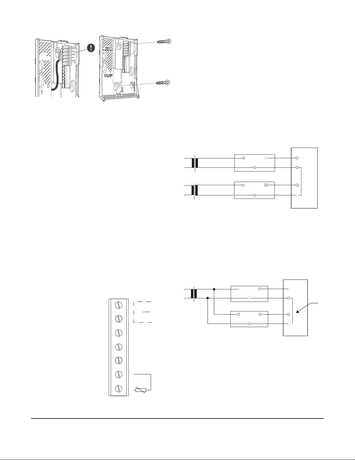
Figure 3: Route the Cable From Behind (Left)
and Mount the Wall Plate (Right)
N
O
C
A
B
L
E
S
U
P
Figure 4: Screw Terminals
+CO2
4...20mA
+CO2
0...10 V
-CO2
VS
~
Signal Out 0 to 10 V (+)
Signal Common (-)
Power Supply Common (-)
Power Supply 24 VAC/DC (+)
Temperature Sensor
Temperature Sensor Common
FIG:CO2_wrng
Figure 5: Connecting Separate AC Supplies
(Recommended)
Supply
voltage
24 VAC
mA or V
Common
Signal
output
CO2 Transmitter/
Module
CO2 Transmitter/
Module
24V
Commo n
Supply
voltage
24 VAC
F
I
G
:
c
o
n
n
_
s
e
p
a
c
Figure 6: Connecting One AC Supply to Several
Transmitters (Not Recommended)
Supply
voltage
24 VAC
mA or VA
Common
Signal
output
CO2 Transmitter/
Module
CO2 Transmitter/
Module
24V
mA or VA
Common
Supply
voltage
Signal
output
F
I
G
:
c
o
n
n
_
s
n
g
s
e
v
LINE
the cable opening. If left unsealed, the hole allows air
from outside the room into the transmitter and affects
the measurement readings. For example, fresh
concrete binds CO
and may cause low readings,
2
especially in new buildings.
Connecting the Cable to the Mounting Base
Connect the wires from the cable to the screw
terminals on the mounting base. The terminal
assignments are marked next to the screw terminals.
Maximum wire size is 2 mm
2
(AWG 14).
Note: The transmitter is capable of generating both
voltage and current output. Each output has its own
individual positive screw terminal.
Power Supply Requirements
The transmitter requires a 24 VAC/VDC, Class 2 power
supply. Although the power input includes a halfwave
rectifier, we recommend using a DC supply to avoid
excessive current peaks.
Connections to a 24 VAC Power Supply
Connecting more than one transmitter to a single
24 VAC transformer forms a common loop and
increases the risk of a short circuit. We recommend
that you use a separate floating supply for each
transmitter (see Figure 5).
CONTROLLER
24V
mA or V
Signal
output
1. Strip 1/4 in. (6.35 mm) of insulation from the ends
of the power and output signal wires.
Note: To prevent a short circuit from occurring, make
sure that the wires are stripped to the correct length
and fully inserted into the terminal blocks. If using
shielded cable, ensure that the shield is protected from
contact with components on the top or bottom side of
the printed circuit board. Failure to follow proper wiring
procedures may cause the transmitter to fail.
2. Connect the wires to the mounting base screw
terminals as shown in Figure 4.
Signal Out 4 to 20 mA (+)
CD-W00-x0-2 Series Wall Mount CO2 and Temperature Transmitters Installation Instructions
If several transmitters share a common transformer,
always connect the transmitter common (-) to the same
side of the transformer to maintain the polarity. A
shared common line at the controller may cause a
short circuit if the phase is not the same (Figure 6).
CONTROLLER
24V
SHARED
COMMON
+
-
Completing the Installation
Install the cover on the mounting base:
t+
1. Slide the bottom of the cover onto the tabs at the
bottom of the mounting base.
2. Tilt the top of the cover toward the mounting base.
3
Page 4

3. Insert the locking screw on the top of the
CF
Altitude (Feet)
1.25
1.20
1.15
1.10
1.05
1.00
0.95
0.90
1,000 2,000 3,000 4,000
5,000
6,000
7,000
0
F
I
G
:
a
l
t
c
o
m
p
_
f
t
Figure 7: Altitude Compensation, Feet above Sea Level
CF
Altitude (Meters)
1.15
1.10
1.05
1.00
0.95
0.90
1.20
1.25
F
I
G
:
a
l
t
c
o
m
p
_
m
Figure 8: Altitude Compensation, Meters above Sea Level
transmitter and secure the locking screw with a
#1 Phillips-Head screwdriver.
If power is supplied to the screw terminals, the
transmitter starts when you close the cover.
Setup and Adjustments
Commissioning
CD-W00-x0-2 Series Wall Mount CO2 and
Temperature Transmitters come from the factory
calibrated for the following:
• output signal (0 to 10 V and 4 to 20 mA)
proportional to CO
per million [ppm])
concentration (0 to 2,000 parts
2
1.30
• altitude range of 0 to 2,000 ft (0 to 600 m) without
compensation
For altitudes above 2,000 ft (600 m) where optimum
accuracy of the CO
concentration measurement is
2
essential, modify the Building Automation System
(BAS) controller’s analog input (AI) high range to
compensate for sensor placement at other than the
standard calibration altitude.
To do this, reset the 2,000 ppm value using the
controller’s compensation factor (CF) shown in
Figure 7 or Figure 8.
Calculate the corrected value:
Corrected Value = CF x 2,000
For example, if the sensor is situated at an altitude of
3,000 ft (914.4 m) above sea level, the CF is 1.10 (see
Figure 7 or Figure 8). The corrected value is:
Corrected Value = (1.10)(2,000 ppm) = 2,200 ppm
Note: For altitude compensation, only adjust the AI
high range. The AI low range should remain at zero.
1.30
0 200 400 600 800 1,000 1,200 1,400 1,600 1,800 2,000 2,200
CD-W00-x0-2 Series Wall Mount CO2 and Temperature Transmitters Installation Instructions
4
Page 5

Troubleshooting
The CO2 transmitter is not field repairable. In the event
the unit is not functioning properly, identify the
symptoms and determine a solution:
1. Verify that the unit is mounted properly.
2. Verify that all wiring is correct.
3. Verify that the power supply voltage level is
20 to 30 VAC or 18 to 30 VDC.
If the CO
completing these steps, replace the unit.
Repair Information
If the CD-W00-x0-2 Series Wall Mount CO2 and
Temperature Transmitters fail to operate within their
specifications, replace the units. For a replacement
CO
2
Johnson Controls® representative.
transmitter does not operate after
2
transmitter, contact the nearest
Technical Specifications
CD-W00-x0-2 Series Wall Mount CO2 and Temperature Transmitters
CO2 Measuring Range 0 to 2,000 ppm CO
CO2 Accuracy Across Temperature
Range
Long-Term Stability ±(15 ppm +2% of reading) over 5 years
Response Time (0 to 63%) 1 minute
Platinum Temperature Sensor Temperature Sensor: 1,000 ohm, Class F0.15 IEC60751 (Class A), thin-film
Operating Temperature Range 32 to 122°F (0 to 50°C)
Storage Temperature Range -40 to 158°F (-40 to 70°C)
Operating Humidity Range 0 to 95% RH (noncondensing), 86°F (30°C) maximum dew point
Transmitter CO
Resolution of Analog Outputs 0.3 ppm CO
Recommended External Load Minimum 1,000 ohms load resistance for 0 to 10 V
Power Supply Range 24 VAC ±20%, 50/60 Hz (18 to 30 VDC), Class 2
Power Consumption <1.0W Average, excluding current output consumption
Current Consumption 100 mA Peak on AC power; 45 mA Peak on DC power
Warm-Up Time <1 minute
Dimensions (H x W x D) 5 x 3-3/16 x 1-1/32 in. (127 x 81 x 26 mm)
Shipping Weight 0.25 lb (114 g)
Compliance United States UL Listed, File E107041, CCN PAZX, UL 916, Energy Management Equipment,
Output Signal 4 to 20 mA and 0 to 10 VDC
2
Europe CE Mark - Johnson Controls, Inc. declares that this product is in compliance with
Canada UL Listed, File E107041, CCN PAZX7, CAN/CSA C22.2 No. 205-12, Energy
Australia and
New Zealand
68 to 86°F (20 to 30°C): ±(30 ppm +3% of reading)
50 to 68°F (10 to 20°C), 86 to 104°F (30 to 40°C): ±(35 ppm +3.7% of reading)
32 to 50 °F (0 to 10°C), 104 to 122°F (40 to 50°C): ±(40 ppm +4.8% of reading)
platinum
Temperature Coefficient: Approximately 2 ohms per F° (3.9 ohms per C°)
Reference Resistance: 1,000 ohms at 32°F (0°C)
Accuracy: ±0.34F° at 70°F (±0.18C° at 21°C)
Maximum Output Current: 21 mA; Maximum Output Voltage: 11 V
Maximum 600 ohm load resistance for 4 to 20 mA
<10 minutes for full specification
FCC Compliant to CFR 47, Part 15, Subpart B, Class A
the essential requirements and other relevant provisions of the EMC directive.
Management Equipment, Industry Canada Compliant, ICES-003
RCM Mark, Australia/NZ Emissions Compliant.
2
2
The performance specifications are nominal and conform to acceptable industry standards. For application at conditions beyond these
specifications, consult the local Johnson Controls office. Johnson Controls, Inc. shall not be liable for damages resulting from misapplication or
misuse of its products.
CD-W00-x0-2 Series Wall Mount CO2 and Temperature Transmitters Installation Instructions
5
Page 6

Global Safety Information
English
• Make sure that the line power supply is in accordance
with the power supply specified in the Technical
Specifications section.
• This sensor / transmitter is to be used mounted on the
wall only.
• All wiring should conform to local codes and must be
carried out by authorized personnel only.
• Keep high and low voltage wiring separated.
• When using multi-stranded wire apply a cable ferrule to
the cable end.
• Check all wiring connections before applying power to the
system.
• Contact with components carrying hazardous voltage can
cause electric shock and may result in severe injury or
death.
• Short-circuited or improperly connected wires may result
in permanent damage to the equipment.
• Not adhering to these operational instructions could
cause injury or damage the equipment.
• If the cable between the sensor and the controller is over
3 meters, it should be shielded. The shield would be
connected at the controller end of the cable.
• Retain this document.
Français
• Assurez-vous que la source électrique est conforme à
l’alimentation spécifiée à la section Caractéristiques
techniques.
• Ce(tte) sonde / transmetteur doit être monté(e) en
position murale uniquement.
• Le raccordement électrique doit être réalisé par le
personnel autorisé conformément aux prescriptions
locales.
• La tension d’alimentation et la basse tension doivent être
amenées séparément
• En cas d’utilisation de câbles flexibles, il faut utiliser des
cosses de câble
• Contrôlez toutes les liaisons par câble avant de mettre le
vérin en circuit
• Le contact avec des composants porteurs de tensions
dangereuses peut causer une décharge électrique et peut
entraîner des blessures graves ou la mort.
• Des fils en court-circuit ou mal branchés peuvent
entraîner des dommages permanents pour l'équipement
• Ne pas respecter le présent mode d'emploi peut
provoquer des blessures ou endommager le matériel
• "Si le câble entre la capteur et le régulateur dépasse
3 mètres, il doit être blindé. Le blindage devra être
connecté vers l'extrémité du câble coté régulateur."
• Conserver ce document
Deutsch
• Stellen Sie sicher, dass die Spannungsversorgung den
Anforderungen im Abschnitt Technische Daten entspricht.
• Dieser Sensor / Transmitter kann nur wandmontiert
eingesetzt werden.
• Der elektrische Anschluß ist nach den örtlichen
Vorschriften durch autorisiertes Personal durchzuführen.
• Versorgungsspannung und Niederspannung sind
getrennt zuzuführen
• Bei Verwendung von flexiblen Leitungen sind
Kabelschuhe zu verwenden
• Überprüfen Sie alle Kabelverbindungen bevor Sie den
Antrieb einschalten.
• Der Kontakt mit Komponenten, auf denen gefährliche
Spannung anliegt, kann zu einem Stromschlag führen
und schwere Körperschäden oder sogar den Tod zur
Folge haben
• Kurzgeschlossene oder falsch angeschlossene Drähte
können bleibende Schäden am Gerät verursachen
• Die Missachtung dieser Bedienungsanleitung könnte zu
Verletzungen oder zu Beschädigungen des Equipments
führen.
• Wenn das Kabel zwischen die Fühler und dem Regler
länger als 3 m ist, sollte ein abgeschirmtes Kabel
verwendet werden, dessen Abschirmung reglerseitig
anzuschließen ist
• Bewahren Sie dieses Dokument auf
Italiano
• Assicurarsi che la tensione di alimentazione sia in
accordo con quanto indicato nel paragrafo Specifiche
Tecniche.
• Questo sensore / trasmettitore deve essere installato solo
a parete.
• L’allacciamento elettrico deve essere eseguito da
personale autorizzato e conformemente alle normative
locali.
• La tensione di alimentazione e la bassa tensione devono
essere alimentate separatamente
• In caso di impiego di conduttori flessibili usare degli
ancoraggi per cavi
• Prima di inserire l’azionamento controlare tutti gli
allacciamenti dei cavi
• Il contatto con componenti sottoposti a tensioni pericolose
può causare scosse elettriche con conseguenti lesioni
gravi o morte.
• I cavi in corto circuito o collegati impropriamente
potrebbero causare danni permanenti
all'apparecchiatura.
• Non attenersi alla presente istruzione operativa potrebbe
causare danni alle persone o alle attrezzature
• Se la lunghezza del cavo tra il sensore e il controllore è
superiore ai 3 metri, il cavo stesso dovrebbe essere
schermato. La schermatura deve essere collegata
all'estremità del cavo dalla parte del controllore.
• Conservare questo documento
Español
• Asegúrese de que la alimentación de red coincide con las
especificaciones de alimentación en el apartado de
Especificaciones técnicas.
• Este sensor / transmisor solo puede utilizarse si está
montado en pared.
• La conexión eléctrica deberá ser realizada según las
disposiciones locales y por personal autorizado.
• La tensión de alimentación y la baja tensión deben
tenderse por separado.
CD-W00-x0-2 Series Wall Mount CO2 and Temperature Transmitters Installation Instructions
6
Page 7

• Al usar cables flexibles, deberán utilizarse terminales de
cable.
• Comprobar todas las conexiones de cables, antes de
conectar el accionamiento.
• El contacto con elementos portadores de alto voltaje
puede provocar una descarga eléctrica y producir
lesiones graves o incluso la muerte
• Los cables cortocircuitados o mal conectados pueden
provocar daños permanentes en el equipo
• El incumplimiento de estas instrucciones de
funcionamiento puede causar lesiones personales o
daños en el equipo
• En caso de que la longitud del cable conectado entre el
sensor y el controlador sea superior a 3 metros, entonces
este deberá ser apantallado. El apantallamiento deberá
estar conectado en la parte del controlador.
• Conserve este documento
Nederlands
• Zorg ervoor dat de elektrische voeding overeenkomt met
de elektrische voeding zoals vermeld in het Technische
Specificaties-gedeelte.
• Deze opnemer alleen gemonteerd aan de muur
toepassen.
• De elektrische aansluiting moet volgens de plaatselijke
voorschriften door geautoriseerd personeel uitgevoerd
worden.
• Voedingsspanning en laagspanning moeten afzonderlijk
toegevoerd worden.
• Bij het gebruik van flexibele leidingen moeten
kabelschoenen gebruikt worden.
• Controleer alle kabelverbindingen voor u de aandrijving
inschakelt
• Contact met onderdelen met een gevaarlijke spanning
kan elektrische schokken veroorzaken en ernstig letsel of
de dood tot gevolg hebben
• Kortsluitingen of verkeerd aangesloten bedradingen
kunnen permanente schade aan de apparatuur tot gevolg
hebben
• Het niet naleven van deze gebruiksinstructies kan leiden
tot persoonlijk letsel of schade aan de apparatuur
• Wanneer de kabel tussen de voeler en de Controller
langer is dan 3 meter is het noodzakelijk om
afgeschermde kabel te gebruiken. De kabel afscherming
moet aangesloten worden aan de Controller.
• Bewaar dit document.
Svenska
• Försäkra dig om att strömförsörjningen är i enlighet med
strömförsörjningen som anges I tekniska specifikations
sektionen.
• Denna givare är endast för väggmontage.
• Elanslutningen ska utföras av behörig personal i enlighet
med de lokala föreskrifterna.
• Försörjningsspänning och lågspänning ska tillföras åtskilt
• Vid användning av flexibla ledningar ska kabelskor
användas
• Kontrollera alla kabelförbindelser innan du tillkopplar
ställdonet
• Kontakt med komponenter med farlig spänning kan ge
elektriska stötar som kan orsaka allvarliga eller
livshotande personskador
• Kortslutna eller felaktigt anslutna kablar kan resultera i
varaktiga skador på utrustningen.
• Om innehållet i den här bruksanvisningen inte efterföljs
kan det leda till skada på person eller utrustning.
• Om anslutningskabeln mellan temperaturgivare och
styrenheten är längre än 3 meter, bör man använda
skärmad kabel. Skärmen ansluts i den ändan som
kopplas in i styrenheten
• Behåll det här dokumentet.
Cesky
• Zkontrolujte, že napájecí zdroj odpovídá požadavkům na
napájení, uvedených v části Technické údaje.
• Tento snímač / převodník je určen pouze pro montáž na
stěnu.
• Veškerá zapojení by měla odpovídat místním předpisům
a musí být prováděna pouze oprávněnými pracovníky.
• Vysokonapěťová a nízkonapěťová vedení oddělte
• Pri použití vícežilového kabelu instalujte do pruchodky
gumový tesnicí kroužek
• Před připojením systému ke zdroji napájení proveďte
kontrolu všech zapojení.
• Kontakt se součástmi, které jsou pod napětím, může
způsobit zasažení elektrickým proudem a vážný úraz
nebo smrt.
• Zkratované nebo nesprávně připojené vodiče mohou
způsobit nevratné poškození zařízení.
• Nedodržení těchto provozních pokynů by mohlo způsobit
zranění nebo poškození zařízení
• Pokud je délka kabelu mezi čidlo a kontrolérem větší než
3 metry, kabel musí být stíněný. Stínění by mělo být
uzeměno pouze na jednom konci u kontroléru.
• Tento dokument uschovejte.
Polski
• Upewnij się, czy napięcie zasilania jest zgodne z
napięciem wyspecyfikowanym w odpowiedniej sekcji
dokumentacji technicznej.
• Ten czujnik/nadajnik przeznaczony jest tylko do
zamontowania na ścianie.
• Okablowanie musi być zgodne z lokalnymi przepisami i
jego montaż musi być przeprowadzany wyłącznie przez
uprawniony personel.
• Należy odseparować kable niskiego napięcia od
okablowania wysokiego napięcia.
• W przypadku stosowania kabla wielożyłowego należy
założyć tulejkę na jego koniec
• Przed włączeniem zasilania systemu należy sprawdzić
wszystkie połączenia kabli.
• Dotknięcie elementów będących pod niebezpiecznym
napięciem może spowodować porażenie i poważne
obrażenia lub nawet śmierć.
• Zwarcia lub nieprawidłowo podłączone kable mogą
spowodować trwałe uszkodzenie urządzeń
• Nieprzestrzeganie niniejszych instrukcji użytkowania
może spowodować obrażenia lub uszkodzenie sprzętu.
• Jeżeli przewód pomiędzy czujnik i sterownikiem jest
dłuższy niż 3 mietry, powinien być ekranowany. Ekran
.
CD-W00-x0-2 Series Wall Mount CO2 and Temperature Transmitters Installation Instructions
7
Page 8

Metasys® and Johnson Controls® are registered trademarks of Johnson Controls, Inc.
All other marks herein are the marks of their respective owners. © 2016 Johnson Controls, Inc.
Building Efficiency
507 E. Michigan Street, Milwaukee, WI 53202
powinien być wtedy podłączony jedynie po stronie
sterownika.
• Niniejszy dokument należy zachować.
Russian
• Убедитесь что линия питания соответствует питаннию
указанному в разделе Технической Спецификации
• данный передатчик\сенсор используется только для
монтажа на стене.
• "Все электрические цепи и соединения должны
соответствовать местным нормам и правилам и
должны выполняться только уполномоченным
персоналом."
• Прокладывайте цепи высокого и низкого напряжения
отдельно
• В случае применения много жильного
заключите конец провода в наконечник.
• Проверьте все проводные соединения, прежде чем
подавать питание на систему.
• Прикосновение к частям и элементам, находящимся
под опасным напряжением, может привести к
серьезному увечью или смерти в результате
поражения электротоком.
• Короткое замыкание или неправильное подключение
электрических цепей может привести к
неустранимому повреждению оборудования
•
Несоблюдение настоящих указаний может стать
причиной несчастного случая или повреждения
оборудования.
• если кабель между Датчик и контроллером
составляет более 3 метров, то должен быть
экранирован. Экран следует заземлять в одной точке
на стороне контроллера.
• Сохраните этот документ
провода
Portuguese
• Certifique-se que a fonte de alimentação é compatível
com a fonte de alimentação especificada na secção de
Especificação Técnica.
• Este sensor / transmissor foi projetado para montagem
somente em parede.
• Toda a fiação eletrica devera ser realizadas segundo a
disposicão locais e apenas por pessoal autorizado
• Manter os fios de alta tensão e baixa separados
• Ao usar fio flexivel aplicar na extremidade do cabo
terminais
• Verifique todas as ligações antes de ligar para o sistema
• Contato com os componentes portadores de alte tensão
pode provocar choque elétrico e podem resultar
ferimentos graves ou morte
• Curto-circuito ou fios mal conectados podem provocar
danos permanentes no equipamento.
• Não aderir a estas instruções operacionais pode provocar
ferimentos ou danos ao equipamento
• Se o cabo entre o sensor e o controlador é superior a
3 metros,este deve ser protegido. O escudo deve ser
ligado no lado do controlador na extremidade do cabo
• Guarde este documento
Chinese
• 确保线电源与技术规格章节中要求的电源保持一
致。
• 该传感器 / 变送器仅被用于安装在墙壁上。
• 毖 : 该传感器仅适用于风管 .
• 所有接线必须符合当地电器规范,并由具有资质的
人员进行接线
• 将高压和低压线分离
• 当使用多股线时,请在电缆末端安装金属套圈
• 确保所接的电源规格符合产品所规定的电源要求
• 系统通电前检查所有接线是否准确
• 触碰带有危险电压的部件可能引起触电,并可导致
人员受伤或死亡
• 短路或者错误接线会导致设备永久性损坏
• 不遵守这些操作指南会导致人员受伤或者机器损坏
• 如果传感器和控制器的距离超过 3 米,需采用屏蔽
线
• 保存此文档
•
European Single Point of Contact: NA/SA Single Point of Contact: APAC Single Point of Contact:
JOHNSON CONTROLS
WESTENDHOF 3
45143 ESSEN
GERMANY
CD-W00-x0-2 Series Wall Mount CO2 and Temperature Transmitters Installation Instructions8
Published in U.S.A. www.johnsoncontrols.com
JOHNSON CONTROLS
507 E MICHIGAN ST
MILWAUKEE WI 53202
USA
JOHNSON CONTROLS
C/O CONTROLS PRODUCT
MANAGEMENT
NO. 22 BLOCK D NEW DISTRICT
WUXI JIANGSU PROVINCE 214142
CHINA
 Loading...