

Page 1
24-9601-0, Rev. C
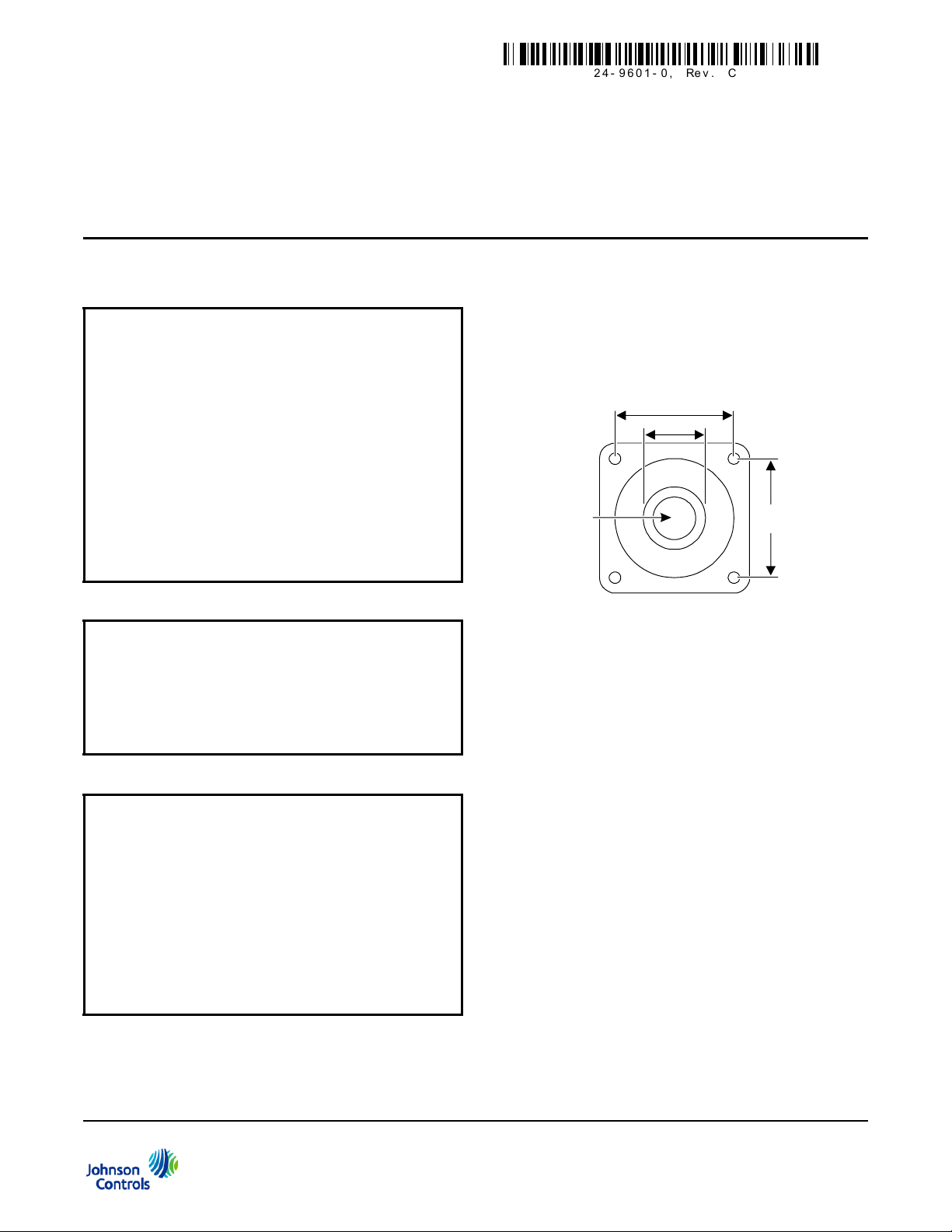
Figure 1: Mounting Holes on the Flange
Dimensions in. (mm)
0.87 (22)
Center
Hole
1.65 (42)
1.54 (42)
FIG:dim
CD-Pxx-00-0 Series Duct Mount CO2 Transmitter
Installation Instructions
CD-Pxx-00-0
Refer to the QuickLIT website for the most up-to-date version of this document.
Part No. 24-9601-0, Rev. C
Issued April 2016
North American Emissions Compliance
United States
This equipment has been tested and found to
comply with the limits for a Class A digital device
pursuant to Part 15 of the FCC Rules. These limits
are designed to provide reasonable protection
against harmful interference when this equipment is
operated in a commercial environment. This
equipment generates, uses, and can radiate radio
frequency energy and, if not installed and used in
accordance with the instruction manual, may cause
harmful interference to radio communications.
Operation of this equipment in a residential area is
likely to cause harmful interference, in which case
the user will be required to correct the interference
at his/her own expense.
Canada
This Class (A) digital apparatus meets all the
requirements of the Canadian Interference-Causing
Equipment Regulations.
Cet appareil numérique de la Classe (A) respecte
toutes les exigences du Règlement sur le matériel
brouilleur du Canada.
Installation
Parts Included
The duct mount CO2 transmitter is shipped assembled.
It consists of three main pa rts: ba se and Pr inted Circuit
Board (PCB), cover, and mounting flange with four
screws (for probe depth adjustment). A conduit adaptor
is also included.
Dimensions
Mounting
Location Considerations
When selecting a location for the transmitter, note the
following:
• The transmitter is designed for duct mounting in
any position.
IMPORTANT: The CD-Pxx-00-0 Duct Mount CO
Transmitter is intended to provide an input to
equipment under normal operating conditions.
Where failure or malfunction of the transmitter could
lead to personal injury or property damage to the
controlled equipment or other property, additional
precautions must be designed into the control
system. Incorporate and maintain other devices,
such as supervisory or alarm systems or safety or
limit controls, intended to warn of or protect against
failure or malfunction of the transmitter.
CD-Pxx-00-0 Series Duct Mount CO2 Transmitter Installation Instructions
2
• The probe is best mounted in the return airstream.
• The device should penetrate the duct by a
minimum of 3.0 in. (76.2 mm) to ensure the
sensing part of the element is fully in the airstream.
• The transmitter should be placed in an area free of
condensation.
The transmitter is duct mounted using a flange. The
mounting flange adjusts the distance betwee n the
probe and the inner duct wall. Fasten the mounting
flange with the four screws as follows:
1. Loosen the probe retention screw, and separate
the flange from the assembled unit.
2. Drill a hole 7/8 to 1 in. (22 to 25 mm) diameter in
the duct for the transmitter’s probe.
1
Page 2
3. Using the mounting flange as a template centered
Figure 2: Connecting Separate AC Supplies
(Recommended)
~
+
~
-
~
+
~
-
0
Shared
Common
Line
24 VAC
Supply
Voltage
CO Transmitter
2
24 VAC
Supply
Voltage
Output
SignalsCO Transmitter
2
Controller
V
0
mA
or
V
mA
or
FIG:conn ac1
0
Line
Supply
Voltage
CO Transmitter
2
24 VAC
Supply
Voltage
SignalsCO Transmitter
2
Controller
~
+
~
-
~
+
~
-
mA
or
mA
or
FIG:conn_ac2
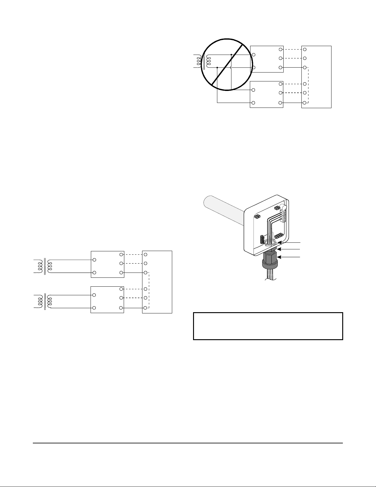
Figure 3: Connecting One AC Supply to Several
Transmitters (Not Recommended)
Figure 4: Inserting the Conduit Adaptor
Nut
Adaptor Body
Adaptor
FIG:ins_cond
on the hole, drill four 1/8 in. (3.18 mm) holes for the
mounting screws positioned as in Figure 1.
4. Fasten the mounting flange onto the duct using the
four screws provided.
5. Insert the probe a minimum of 3.0 in. (76 .2 mm) ,
and tighten the probe retention screw on the
mounting flange.
Wiring
Power Supply Requirements
The transmitter requires a 24 VAC/VDC, Class 2 power
supply maintaining voltages of 18 to 30 VDC or 20 to
30 VAC. Although the power input includes a halfwave
rectifier, we recommend using a DC supply to avoid
excessive current peaks (current consumption: peak,
170 mA; average, 85 mA).
24 VAC Power Supply Connections
When more than one transmitter is connected to one
24 VAC transformer, a common loop is formed at the
controller, an d the risk of a short circuit increases.
All commons must be at the same potential.
Output
V
0
Shared
V
Common
Connecting the Conduit Adaptor
1. Align the nut with the opening inside the enclosure,
and hold it in place.
2. Insert the adaptor body into the transmitter conduit
opening.
3. Manually tighten the adaptor into the nut, turning in
a Clockwise (CW) direction (see Figure 4).
Note: To avoid a short circuit, isolate the 24 V power
supply by providing a separate transformer for each
transmitter as shown in Figure 2.
If several transmitters share one transformer, the
phase (~) must always be the same at each transmitter
to maintain polarity and avoid a short circuit via a
shared common line at the controller, as shown in
Figure 3.
IMPORTANT: Do not overtighten the conduit
adaptor. Overtighting the conduit adaptor may
damage or displace the PCB.
4. Insert the wires through the conduit adaptor body
opening.
5. Tighten the adaptor onto the adaptor body by
turning the adaptor in a CW direction.
Wiring the PCB
To wire the PCB’s input and output connections:
CD-Pxx-00-0 Series Duct Mount CO2 Transmitter Installation Instructions
1. Open the transmitter cover.
2
Page 3
2. Insert the wire carefully through the conduit
S
V7
X3
X6
X5
FIG:trans_PCB
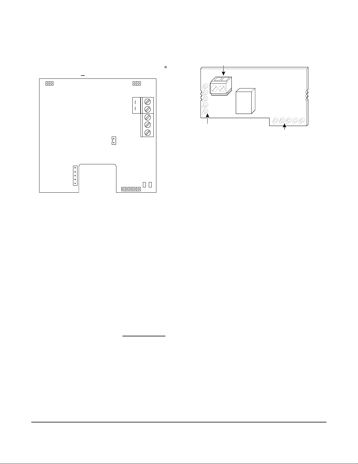
Figure 5: Transmitter PCB
Screw Terminals
Connect to X5
FIG:Rel_PCB
Figure 6: Relay PCB
adaptor and then strip 1/4 in. (6.35 mm) of the wire
insulation to prepare the wire for connection to the
terminal block.
3. Connect the 24V supply between the po sitiv e ( )
and negative ( ) terminals as shown in Figure 5.
~
X7
— +
~
Wiring the Relay
Model CD-PR0-00-0 is shipped with a relay module. To
wire the relay, see Figure 6, and attach the relay wires
to the relay PCB's two screw terminals.
mA V 0
0/4mA
ERIAL COM
V10
Configuring the Output
The transmitter is capable of generating either voltage
or current output. To select, refer to Figure 5 and:
1. Connect the common wire to Terminal 0.
2. Connect the other wire to:
• Terminal V (for voltage output)
• Terminal mA (for current output) and configure
the pins marked 0/4mA as follows:
- 4 to 20 mA: connect the jumper so that it
shorts the pins (default)
- 0 to 20 mA: disconnect (do not discard) the
jumper
Connect to X3
The relay has two setpoint values: the On level and the
Off level. These levels provide hysteresis and desired
control function. The On level must be higher than the
Off level. When CO
concentration is increasing; the
2
relay closes at the On level, and the relay opens when
concentration is reduced to the Off level.
Note: The default relay setpoints are 1,000 ppm On
and 950 ppm Off. Change these settings by entering
new values using the Relay Setpoint Software
ACCCDS.
Setup and Adjustments
Commissioning
Johnson Controls® Carbon Dioxide (CO2) transmitters
come from the factory calibrated for the following:
• output signal (0 to 10 V) proportional to CO
concentration (0 to 2,000 parts per million [ppm])
• altitude range of 0 to 1,969 ft (0 to 600 m) above
sea level without compensation
• default relay output trigger point of 1,000 ppm
2
3. If the unit has an optional relay accessory, follow
the procedure described in the Wiring the Relay
section and then reposition the cover .
CD-Pxx-00-0 Series Duct Mount CO2 Transmitter Installation Instructions
3
Page 4

Altitude Compensation
CF
Altitude (Feet)
1.25
1.20
1.15
1.10
1.05
1.00
0.95
0.90
01,000
2,000
3,000
4,000
FIG:alt_ft
Figure 7: Altitude Compensation in Feet Above Sea Level
CF
Altitude (Meters)
0200
400
600 800 1,000 1,200 1,400 1,600
1,800 2,000 2,200
1.25
1.20
1.15
1.10
1.05
1.00
0.95
0.90
FIG:alt_mtr
Figure 8: Altitude Compensation in Meters Above Sea Level
The sensors are calibrated for an altitude of 984 ft
(300 m) above sea level and are intended for
applications within the range of 0 to 1,969 ft
(0 to 600 m) without compensation.
For altitudes above 1,969 ft (600 m) where optimum
accuracy of the CO
essential, modify the Building Automation System
(BAS) controller’s Analog Input (AI) high range to
compensate for sensor placement at other than the
standard calibration altitude.
Note: For altitude compensation, only adjust the AI
high range. The AI low range should remain at zero.
1.30
concentration measurement is
2
To modify the controller’s AI, reset the 2,000 ppm value
using the controller's Compensation Factor (CF) shown
in Figure 7 or Figure 8 as follows:
Corrected Value = CF x 2,000
For example, if the sensor is situated at an altitude of
3,000 ft (914.4 m) above sea level, CF, from either
Figure 7 or Figure 8, is 1.10.
The new value is calculated as follows:
Corrected Value = (1.10)(2,000 ppm) = 2,200 ppm
1.30
CD-Pxx-00-0 Series Duct Mount CO2 Transmitter Installation Instructions
4
6,000
7,000
Page 5

Troubleshooting
The transmitter is not field repairable.
In the event the unit is not functioning properly, perform
the following to identify the symptoms and determine a
solution; verify that:
1. the unit is mounted properly and the ap pr o pr iate
output jumper is selected
2. all wiring is correct
3. the power supply voltage level is 20 to 30 VAC or
18 to 30 VDC
Note: The diagnostic Light Emitting Diodes (LEDs)
shown in the lower right-hand corner of Figure 5
indicate operational status:
• V7 lights up if the self-diagnostics procedure
detects an abnormality.
• V10 pulses to indicate that the device is
operational.
If the transmitter does not operate after completing
these steps, replace the unit.
5. Determine whether the contacts are open or
closed.
• If the contacts are closed, the relay is
functioning properly, and no further testing is
necessary.
• If the contacts are open, increase the CO
concentration by exhaling near the probe,
looking for a change in the resistance value.
• If no change is noted, confirm that the CO
concentration has been raised above the trip
point.
- Check the transmitter output signal with a
voltmeter to make sure the signal has risen
above the 1,000 ppm relay trip point.
- If the output signal has not reached the trip
point, it may be necessary to further
increase the CO
concentration.
2
• If the contacts are open after exceeding the trip
point, replace the unit with the appropriate
module, and restart this procedure.
2
2
Testing the Relay Module
To confirm that the relay is operating correctly, perform
the following procedure:
IMPORTANT: To expose the sensing portion of the
probe, loosen the probe retention screw, and
remove the probe from the duct. After testing is
complete, reinstall the probe, and tighten the probe
retention screw.
1. Temporarily shut off power to the unit.
2. Temporarily remove wires connected to the relay
screw terminal.
3. Connect a multimeter to the relay terminals.
4. Read the resistance level to determine whether the
contacts are open or closed.
• If the contacts are closed, replace the unit with
the appropriate relay module, and restart this
procedure.
• If the contacts are open, apply power to the
transmitter.
6. Disconnect power to the transmitter.
7. Disconnect the multimeter from the relay terminals.
8. Reconnect the wires to the relay screw terminal.
9. Reconnect power to the transmitter.
10. Reposition the cover.
Repair Information
If the CD-Pxx-00-0 Series Duct Mount CO2 Transmitter
fails to operate within its specifications, replace the
unit. For a replacement transmitter, contact the nearest
Johnson Controls representative.
CD-Pxx-00-0 Series Duct Mount CO2 Transmitter Installation Instructions
5
Page 6
Metasys® and Johnson Controls® are registered trademarks of Johnson Controls, Inc.
All other marks herein are the marks of their respective owners. © 2016 Johnson Controls, Inc.
Building Efficiency
507 E. Michigan Street, Milwaukee, WI 53202
Technical Specifications
CD-Pxx-00-0 Series Duct Mount CO2 Transmitter
Measuring Range 0 to 2,000 ppm CO
Accuracy at 77°F (25°C) < ±[30 ppm CO2 + 2.0% of reading] (includes manufacturing deviation and drift). All
accuracy specifications reflect testing the transmitters using high-grade, certified
gases. Transmitters are intended for an altitude range of 0 to 1,969 ft (0 to 600 m)
above sea level without compensation
Non-Linearity < 0.5% of Full Scale
Temperature of Dependence of
Output
Long-Term Stability < ±5.0% of Full Scale/5 Years
Response Time (0 to 63%) 1 Minute
Operating Temperature Range 23 to 113°F (-5 to 45°C)
Storage Temperature Range -4 to 158°F (-20 to 70°C)
Humidity Range 0 to 85% non-condensing
Transmitter Output Signal CO
Recommended External Load Current Output: Maximum 500 ohms Load Resistance
Power Supply Range 20 to 30 VAC (18 to 30 VDC), Class 2
Power Consumption < 2.5 W Average, 4.1 VA
Warm-up Time < 5 minutes
Airflow Range 0 to 7,500 ft/Minute (0 to 2,286 m/Minute)
Duct Probe Material Duct Probe Meets Plenum Rating Requirements of UL 1995, Heating and Cooling
Housing Material ABS Plastic
Dimensions (H x W x D) 3-5/32 x 3-3/16 x 8 in. (80 x 81 x 204 mm)
Shipping Weight 0.3 lb (140 g)
Compliance United States UL Listed, CCN XAPX
Canada UL, LIsted XAPX7
Europe CE Mark – Johnson Controls, Inc. declares that the CD-Pxx-00-0 Duct Mount CO2
2
< 0.56% of Full Scale/F° (<0.1% of Full Scale/C°)
Jumper Selectable: 0 to 20 mA or 4 to 20 mA or 0 to 10 VDC (Default)
Maximum Output Current: 25 mA; Maximum Output Voltage: 12.5 V
Maximum 30 V, 0.5 A, Class 2
Voltage Output: Minimum 1,000 ohms Load Resistance
Equipment
Transmitters are in compliance with the essential requirements and other relevant
provisions of the EMC Directive.
2
European Single Point of Contact: NA/SA Single Point of Contact: APAC Single Point of Contact:
JOHNSON CONTROLS
WESTENDHOF 3
45143 ESSEN
GERMANY
CD-Pxx-00-0 Series Duct Mount CO2 Transmitter Installation Instructions 6
Published in U.S.A.
www.johnsoncontrols.com
JOHNSON CONTROLS
507 E MICHIGAN ST
MILWAUKEE WI 53202
USA
JOHNSON CONTROLS
C/O CONTROLS PRODUCT MANAGEMENT
NO.22 BLOCK D NEW DISTRICT
WUXI JIANGSU PROVINCE 214142
CHINA
 Loading...