

Page 1

Figure 1: System 450 Module
Dimensions, mm (in.)
127
(5)
4
Screw
Slots
11
(7/16)
(2-3/8)
75
(2-15/16)
1/2 in. Nominal
Trad e Size
Conduit Hole
22
(7/8)
40
(1-9/16)
DIN Rail
Clips
FIG:sys450_dims
System 450™ Series Control Modules with Relay Outputs
Installation Instructions
C450CBN-2
C450CCN-2
Part No. 24-7664-2845, Rev. B
Issued January 23, 2012
Supersedes December 15, 2011
Application
IMPORTANT: Use this System 450 Series Control
Module with Relay Output only as an operating
control. Where failure or malfunction of the System
450 control module could lead to personal injury or
property damage to the controlled equipment or
other property, additional precautions must be
designed into the control system. Incorporate and
maintain other devices, such as supervisory or
alarm systems or safety or limit controls, intended to
warn of or protect against failure or malfunction of
the System 450 control module.
System 450™ is a family of modular, digital electronic
controls that is easily assembled and set up to provide
reliable temperature, pressure, and humidity control for
a wide variety of Heating, Ventilating, Air Conditioning,
and Refrigeration (HVACR) and commercial/industrial
process applications.
The System 450 control modules allow you to
configure custom application-specific control systems
with up to three input sensors and ten (relay and/or
analog) outputs, including control systems that can
monitor and control temperature, pressure, and
humidity applications simultaneously.
Beginning with firmware Version 2.00, standard
System 450 control modules include the High
Input-Signal Selection and Differential Control fe atures.
See High Input-Signal Selection
Differential Control
on page 16 for more information.
on page 9 and
Installation
13
(1/2)
(3/16)
(Four)
61
61
(2-3/8)
You can easily install and quickly configure a
stand-alone System 450 control module and sensor in
the field as a replacement control for almost any
temperature, pressure, and humidity control.
C450CxN-2 models are Single-Pole, Double-Throw
(SPDT) relay control modules with Liquid Crystal
Display (LCD) and four-button touch pad User Interface
(UI) that allows you to set up a System 450 control
system. C450CBN-2 models provide one SPDT relay.
C450CCN-2 models provide two SPDT relays.
Refer to the System 450 Series Technical Bulletin
(LIT-12011459) for more detailed information on
designing, installing, setting up, and troubleshooting
System 450 Series control systems. The System 450
technical bulletin can be accessed and downloaded on
the Johnson Controls® Online Product Litera tu re Web
site at the following Web address:
http://cgproducts.johnsoncontrols.com/default.aspx
Location Considerations
Observe the following System 450 location guidelines:
• Ensure that the mounting surface can support the
module assembly, mounting hardware, and an
(
user-supplied) panel or enclosure.
• Mount the modules upright and plugged together
a h
orizontal row where po ssible (Figure 3). DI
m
ounting is highly recommended.
• Mount modules on flat even surf
Allow sufficient space for wires and connections.
•
• Mount the modules in locations free of corr
vapors and observe the ambient operating
conditions listed in the Technical Specifications
System 450™ Series Control Modules with Relay Outputs Installation Instructions 1
aces.
y
in
N rail
osive
.
Page 2
• Do not mount the modules on surfaces that are
!
prone to vibration or in locations where radio
frequency or electromagnetic emissions may
cause interference.
Note: If you mount the modules on an uneven
surface, do not damage the housings when
tightening mounting screws. Use shims/washers to
mount module assembly evenly on the surface.
• Do not install the modules in airtight enclosures.
• Do not install heat-generating devices in an
enclosure with the modules that may cause the
temperature to exceed the ambient operating limit.
Mounting
Mount System 450 modules on 35 mm DIN rail
(recommended) or directly to an even wall surface. To
mount modules on DIN rail:
1. Provide a section of 35 mm DIN rail that is longer
than the module assembly width, and mount the
DIN rail horizontally in a suitable location using
appropriate mounting hardware/fasteners.
2. Clip the control module on the rail, position the
upper DIN rail clips on the top rail, and gently snap
the lower clips onto the rail.
3. Clip the remaining power and/or expansion
modules to the right of the control module on to the
DIN rail and plug the 6-pin module connectors
together (Figure 3).
Note: If your System 450 control system uses a
power module, the power module must be plugged
into the right-hand side of the control module.
To direct-mount modules to wall surfaces:
Refer to the control sensor installation instructions for
information on locating and mounting control sensors.
Wiring
See Figure 2 and Table 1 for electrical termination
locations and wiring information. See Technical
Specifications on page 23 for electrical ratings.
WARNING: Risk of Electric Shock.
Disconnect or isolate all power supplies
before making electrical connections.
More than one disconnect or isolation
may be required to completely
de-energize equipment. Contact with
components carrying hazardous voltage
can cause electric shock and may result
in severe personal injury or death.
IMPORTANT: Use copper conductors only. Make
all wiring in accordance with local, national, and
regional regulations.
IMPORTANT: Do not exceed the System 450
module electrical ratings. Exceeding module
electrical ratings can result in permanent da mage to
the modules and void any warranty.
1. Plug the modules together, remove the module
covers, place the assembly against wall surface
horizontally in a suitable location and mark the
mount hole locations on the surface (Figure 1).
2. Install appropriate screw fasteners, leaving screw
heads approximately one to two turns away from
flush to the surface.
3. Place the assembly over screw heads on the
mounting slots, and carefully tighten the mounting
screws.
IMPORTANT: Do not connect 24 VAC supply
power to the System 450 modules before finishing
wiring and checking all wiring connections. Short
circuits or improperly connected wires can result in
damage to the modules and void any warranty.
IMPORTANT: Run all low-voltage wiring and
cables separate from all high-voltage wiring.
Shielded cable is strongly recommended for input
(sensor) and analog output cables that are exposed
to high electromagnetic or radio frequency noise.
System 450™ Series Control Modules with Relay Outputs Installation Instructions2
Page 3

Figure 2: C450CxN-2 Wiring Terminals
C
5V
C
C
are connected
internally.
Internal
SPDT Relay
Normally Closed/Off
Position
LNC1
LNO1
LC1
Low Voltage (<30 V)
Dry-Contact, Line-Voltage
Relay Output Terminals
(See
for Electrical Ratings.)
Technical S pecificatio ns
Some models have
and termi nal block labeled
LNC2, LNO2, and LC 2.
FIG:sys450_rly_cntrl_wir
not
relay and do supply any power to the application.
Note:
The relay output terminals connect to an internal SPDT
Supply Power and
Control Sen sor Term inals
24V
Sn2
Sn3
Sn1
6-Pin
Module
Connector
a second output relay
Table 1: System 450 Terminal Wiring Information
Label Terminal Function Wire Sizes
24V Accepts 24 V AC supply power , when a C450YNN power module is not connected,
and provides power terminal for 24 VAC (humidity) sensors.
5V Provides 5 VDC power for active sensors.
Sn-1, Sn-2,
Sn-3
C
(Three
Terminals)
LNC1, LNC2 Connects control circuit to the Normally Closed (N.C.) contact on the SPDT relay.
LNO1, LNO2 Connects control circuit to the Normally Open (N.O.) contact on the SPDT relay.
LC1, LC2
Accepts passive or active (0–5 VDC) input signals from sensors.
Note: You must position the Active/Passive Sensor Jumper (Figure 3 and
Figure 6) correctly for each sensor in your control system before operating the
system. See Setting Active/Passive Sensor Jumpers for more information.
Provide low-voltage Common connections for 24 VAC power and passive or active
sensors connected to the 5V, Sn1, Sn2, and Sn3 terminals.
Note: The three C terminals are connected internally and can be connected to
ground in the field.
1
Connects line (power) to Common (C) on the SPDT
relay.
Common (C) terminals
0.08 mm
28 AWG to 16 AWG
0.08 mm
28 AWG to 14 AWG
2
to 1.5 mm
2
to 2.5 mm
2
2
1. See Internal SPDT Relay insert in Figure 2 for more System 450 relay contact and terminal information. See T echnical
Specifications for SPDT relay electrical ratings.
System 450™ Series Control Modules with Relay Outputs Installation Instructions 3
Page 4
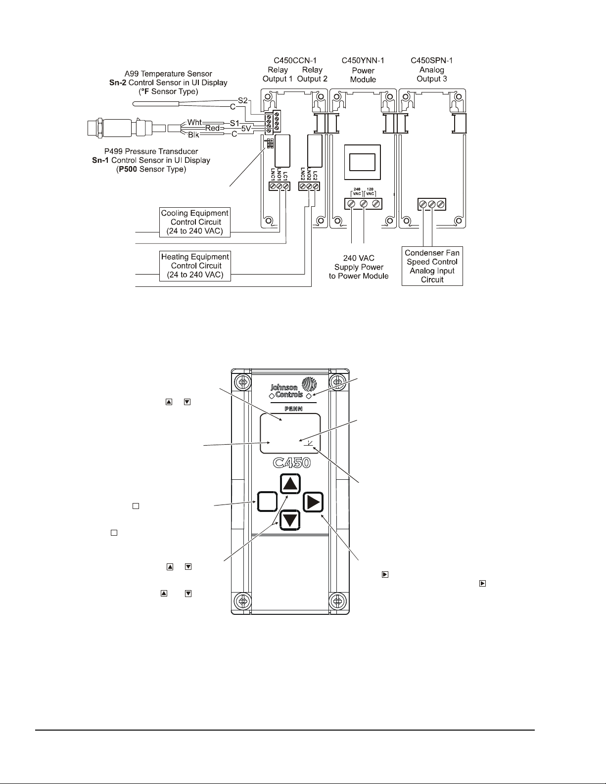
Figure 3: Example System 450 Heat/Cool System with Condenser Fan Speed Control
L2
L1
L2
L1
4-20 mA
Signal
L1 L2
Note:
Sn-1
Sn-2
Sn-3
Active/ P assive Sens or Jumpers
Figure 4: System 450 Control Module Output Relay LEDs,
LCD, Four-Button Touch Pad User Interface
Output Number:
with the stat us or setup va lue shown
on the scr een. Output nu m bers are
automati cally determi ned by the outp uts'
physical positions (left to right) in the
modul e as sembly. (Here, 4 = Output 4.)
Control Ramp Icon:
Displays whether an
or reverse acting, and w hether the out put
signal str ength is at minimum or maximum
when the sensed prop er t y is at Setpoint .
The control ramp icon displayed i s
determi ned by the outp ut's SP, E P, OSP,
and OEP setup values .
Menu Button:
Press to move through the
sensor and output setup start screens.
When moving through the status or setup
screens, press to return to the status start
screen or set up start scr een.
M
M
Status or Setup Id entifier:
or
OSP
Displays the
unit of me asurement, out put, sensor number,
setup parameter for th e di splayed status or
setup val ue. ( Here, the set up identifier
represents % output signal strength at setpoint.)
Up and Down Buttons:
Press or to select
a differ ent value for an y fl ashing value in the
setup val ue f ield. In the Mai n ( sensor status)
screens, pr ess and hold both and for
5 second s to access the Set up Start screen s.
Status or Setup Value:
or
Displays th e current
input stat us, output status setup param et er
value for t he displayed i nput sensor, outp ut
and/or setup parameter. select
a differ ent paramet er value when th e value
is flashing. (Here, 1 00 = 100%.)
Press or to
M
Green LEDs
associat ed relay output is on or off .
In the Main s c reens,
the (flashing) setup value and go to the
next setu p screen.
1
OSP
4
In 120 VAC app li c ations, L1 mu st be the Hot lead
and L2 must be the Neutral/Common lead.
0-10 VDC or
Analog Output
COM
AO2
AO1
FIG:sys450_app_exmpl
Light-Emitting Diode (LED):
on Relay Control Mod ul e and Relay
Expansion Modules (only) indicates if the
System 450™ Series Control Modules with Relay Outputs Installation Instructions4
00
value tha t identifies the output associ at ed
analog out put (only) is set a s direct-acti ng
FIG:sys450cntrl_m odul
Next Button:
press to scroll through the system st atus
screens. In a setup screen, p r ess to save
Displays a numerical
Page 5

Setup and Adjustments
Figure 5: Active/Passive Sensor Terminal Pin
Block Set Up for the Example in Figure 3
Sensor 2:
(or removed) sets Sn-1 to Active (Pressure).
Jumper positioned across two
pins sets Sn-2 to Passive (Temperature).
Jumper positioned across two
pins sets Sn-3 to Passive (Temperature).
Sensor 3:
Sn-1
Sn-2
3
Sys450_jmprs
System 450 Component Requirements
A System 450 control system consists of one control
module, one to three control sensor inputs, and one to
ten outputs that provide On/Off control and/or analog
control. Figure 3 shows an example System 450
module assembly with two input sensors and three
outputs (two relay outputs and one analog output).
Sn-
Sensor 1:
Jumper positioned on one pin
Setting Up a System 450 Module Assembly
To set up a System 450 module assembly:
1. Determine the controlled conditions, sensor types,
and value ranges required for your application, and
select the appropriate System 450 sensor types.
2. Determine the number and type (rela y or analog) of
outputs required to control your application, and
select the appropriate System 450 control module
and expansion modules to provide the outputs.
3. Assemble the control and expansion modules in
the proper order, starting with the control module
on the left.
Note: If you use a C450YNN-1 power module, it
must be plugged into the control module. Plug in
any expansion modules (for your control system) to
the right of the power module.
4. Apply supply power to the module assembly.
You can now set up your control system in the
System 450 reset control module UI.
Note: After you power on your module assembly, you
can set up your control system in the control module UI
before wiring the sensors or outputs to your assembly.
Setting Active/Passive Sensor Jumpers
Before putting your System 450 reset control system
into operation, you must set up each sensor in your
system as either passive or active by positioning the
jumper on the terminal pins on the terminal block
located below the sensor terminal block. See Figure 3.
Temperature sensors are passive (two-wire) sensors
and the corresponding jumpers must be positioned
across both pins. Humidity and pressure transducers
are active (three-wire) sensors and corresponding
jumpers must be positioned on one pin (or removed
completely). Figure 5 shows the jumper positions for
the System 450 example shown in Figure 3.
Setting Up a Control System in the User Interface
System 450 control modules have a backlit LCD and a
four-button touch pad UI (Figure 4) that enable you to
set up your control system. To set up a control system
in the System 450 UI:
1. Build your control system module assembly and
connect it to power. See Setting Up a System 450
Module Assembly on page 5.
Note: Every time a module assembly is powered
ON, the control module polls all of the modules to
identify output type (relay or analog) and assigns a
sequential output number (1 to 9 [0 = 10]) to each
output starting with the control module output on
the left. The output numbers identify each output’s
setup screens in the UI. (See Figure 4.)
2. Access the System 450 setup screens in the UI.
See Accessing the System 450 Setup Start
Screens on page 7.
3. Set up the control system inputs in the UI. See
Setting Up System 450 Sensors
4. Set up the control system outputs in the UI. See
Setting Up System 450 Outputs
IMPORTANT: Do not change the module positions
after a System 450 control system is set up in the UI.
System 450 control logic is set up in the UI according
to the Sensor Types, the o utput types, an d the outpu t
numbers. Changing modules or module positions in a
module assembly that is already set up in the UI can
change the output numbers, output type s, an d the
setup values of the assembly outputs, which requires
setting up the outputs again.
Use the worksheet provided on page 24 to plan and
record the settings for your System 450 control system.
on page 7.
on page 10.
System 450™ Series Control Modules with Relay Outputs Installation Instructions 5
Page 6
Viewing the Startup, Main, and System Status
xxxx
.
2
00
1
74
2
F
OUT
1
On
61
OUT
3
SENS
-- -
OUTR
1
-- -
OUTA
3
-- -
Screens
Every time you connect power to a System 450 control
module, the Startup screen appears for several
seconds before the Main screens appear. The Startup
screen displays the current firmware version for the
module. See Table 2 and System 450 Firmware
Versions for more information.
After you install, wire, power on, and set up your control
system in the UI, the Main screens appear on the LCD,
immediately after the Startup screen. During normal
operation, the Main screens automatically scroll
through the current status of each sensor in your
control system. See Table 2 for more information.
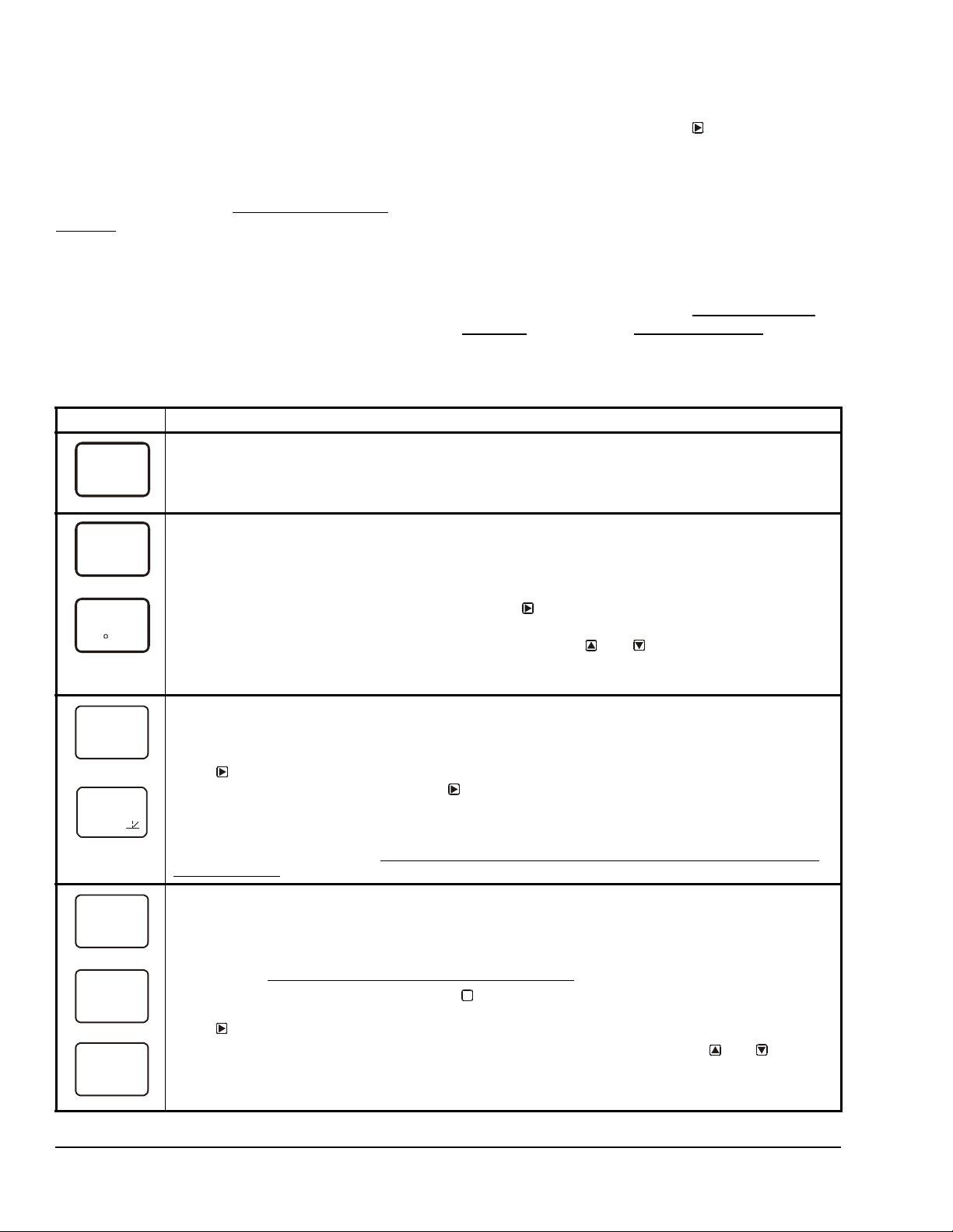
Table 2: System 450 Startup Screen, Main Screens, Status Screens, and Setup Start Screens Information
and Procedures
LCD Screen Name, Description/Function, User Action, and Example
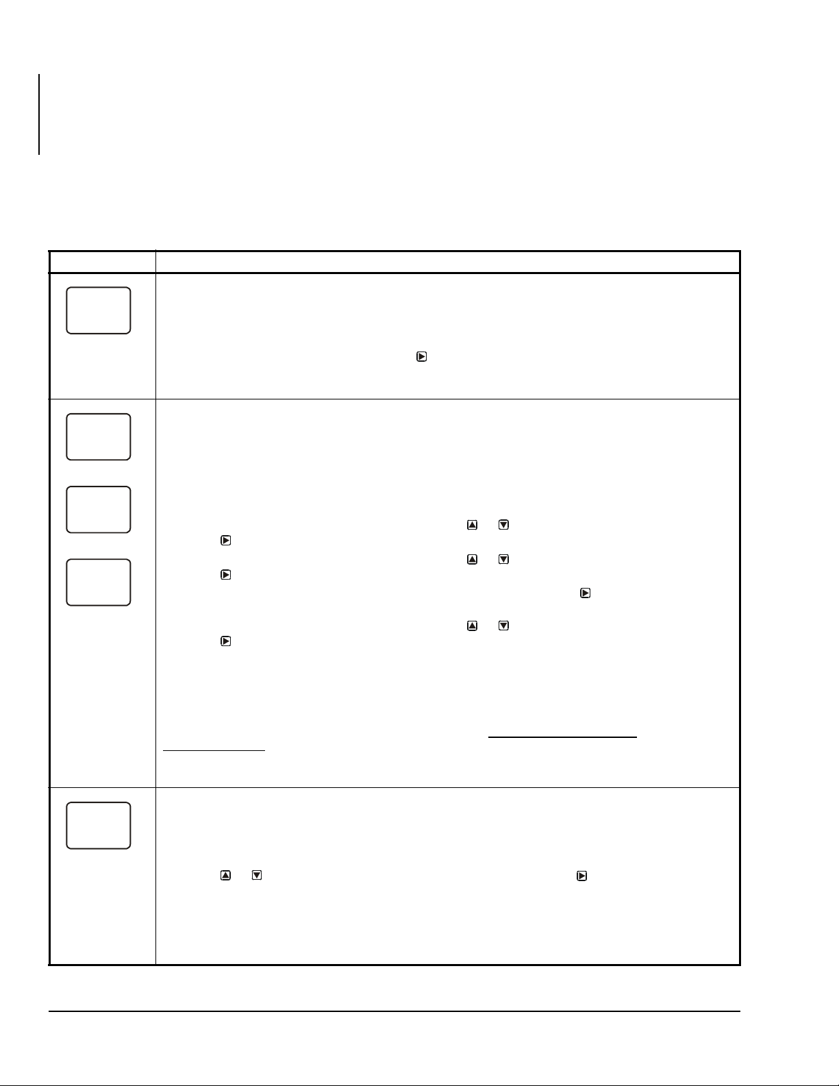
Startup Screen: When you power a System 450 control module, the LCD displays the control module’s
current firmware version for approximately five seconds before it displays the Main (Input Status) screen.
Screen example shows System 450 firmware version number 2.00 on the top of the screen. The number on
the bottom of the screen (indicated in this example with xxxx) identifies the Johnson Controls firmware.
Main (Input Status) Screens: During normal operation, the Main screens automatically scroll through the
232
PSI
current status of each input sensor in your control system and display the sensor number, the unit of
measurement, and the sensed condition value. See Figure 7 and Figure 8 for example Main screens.
Note: Main screens are view-only; selections are not made in Main screens. The Main screens are the
System 450 default screens. After 2 minutes of inactivity in any screen, the UI reverts to the Main screens.
While the Main screens are scroll in g, you can press
System Status screens for all inputs and outputs in your control system.
While the Main Screens are scrolling, you can press and hold and for 5 seconds to access
your control system’s Setup Start screens.
The screen examples show Sensor 1 sensing 232 psi and Sensor 2 sensing 74°F.
System Status Screens: The System Status screens display current status of all inputs and outputs in
your control system. System Status screens are view-only; selections are not made in Status screens.
Relay output status screens display output number and relay status (On/Off). Analog output status screens
display output number, signal strength, and control ramp icon.
Press
control system. When you stop pressing
remains displayed for 2 minutes before returning to the Main Screens.
The screen examples show Output 1 relay is On and Output 3 signal strength is 61% of the total signal
strength. The control ramp icon in the bottom screen example indicates that the Analog Output is set up
with SP<EP and OSP<OEP. See S
Selection Control for information about ramp icons.
Setup Start Screens: Setup Start screens are view-only screens, from which you can access the setup
screens for the sensors or the displayed output; selections are not made in Setup Start screens.The Sensor
Setup Start screen is the first screen displayed when you access the System 450 setup screens.
Note: The numerical order and type of Output Setup Start screens are determined by the modules
selected for your System 450 control system and their physical order in the control system module
assembly. See Setting Up a Control System in the User Interface
From the Sensor Setup Start screen, press repeatedly to scroll through the Output Setup Start
screens for all of the outputs in your control system. When a Setup Start screen is displayed,
press
Note: In any Setup Start screen, you can return to the Main screens by pressing both
simultaneously. Also, the UI returns to the Main screen after 2 minutes of inactivity in any screen.
The screen examples show the Sensor, Relay Output 1, and Analog Output 3 Setup Start screens.
repeatedly to scroll and view the System Status screens for the inputs and outputs in your
etting Up an Analog Output for Standard Control or High Input-Signal
to go to the setup screens for the sensors or the output displayed in the screen.
The System Status screens display the current status
of each input and output in your control system. With
the Main screen displayed, press repeatedly to scroll
through and view all of the status screens in your
control system. See Table 2 for more information about
the System Status screens.
System 450 Firmware Versions
System 450 firmware versions identify the features
available on System 450 modules. Standard System
450 control modules with Version 2.00 firmware and
later include the High Input-Signal Selection and
Differential Control features. See High Input-Signal
Selection on page 9 and Differential Control on page
16 for more information.
repeatedly to scroll through and view the
, the displayed Status screen refreshes its value and
on page 5 for more information.
M
and
System 450™ Series Control Modules with Relay Outputs Installation Instructions6
Page 7
Accessing the System 450 Setup Start Screens
Access the System 450 Setup Start screens from the
Main screen. See Table 2 for more information about
the Setup Start screens.
To access the System 450 setup screens:
1. Apply power to your module assembly. After the
Startup screen appears briefly (displaying the
control module firmware version), the Main screen
appears on the LCD.
3. Press
M
repeatedly to scroll through the Output
Setup Start screens. See Figure 7.
Note: The UI returns to the Main screens after 2
minutes of inactivity in any screen in the UI.
Setting Up System 450 Sensors
You must set up the input sensors for your control
system before you can set up any of outputs. T o set up
the input sensors you must access the setup screens.
See Accessing the System 450 Setup Start Screens
.
2. In the Main screen, press and hold
and
simultaneously for 5 seconds to access the setup
screens and to go to the Sensor Setup Start
screen.
The Sensor Setup Start screen is the first screen
displayed when you access the system setup screens.
Table 3 provides information about System 450
sensors, Sensor Types, parameter values, and
specified sensor/transducer product code numbers.
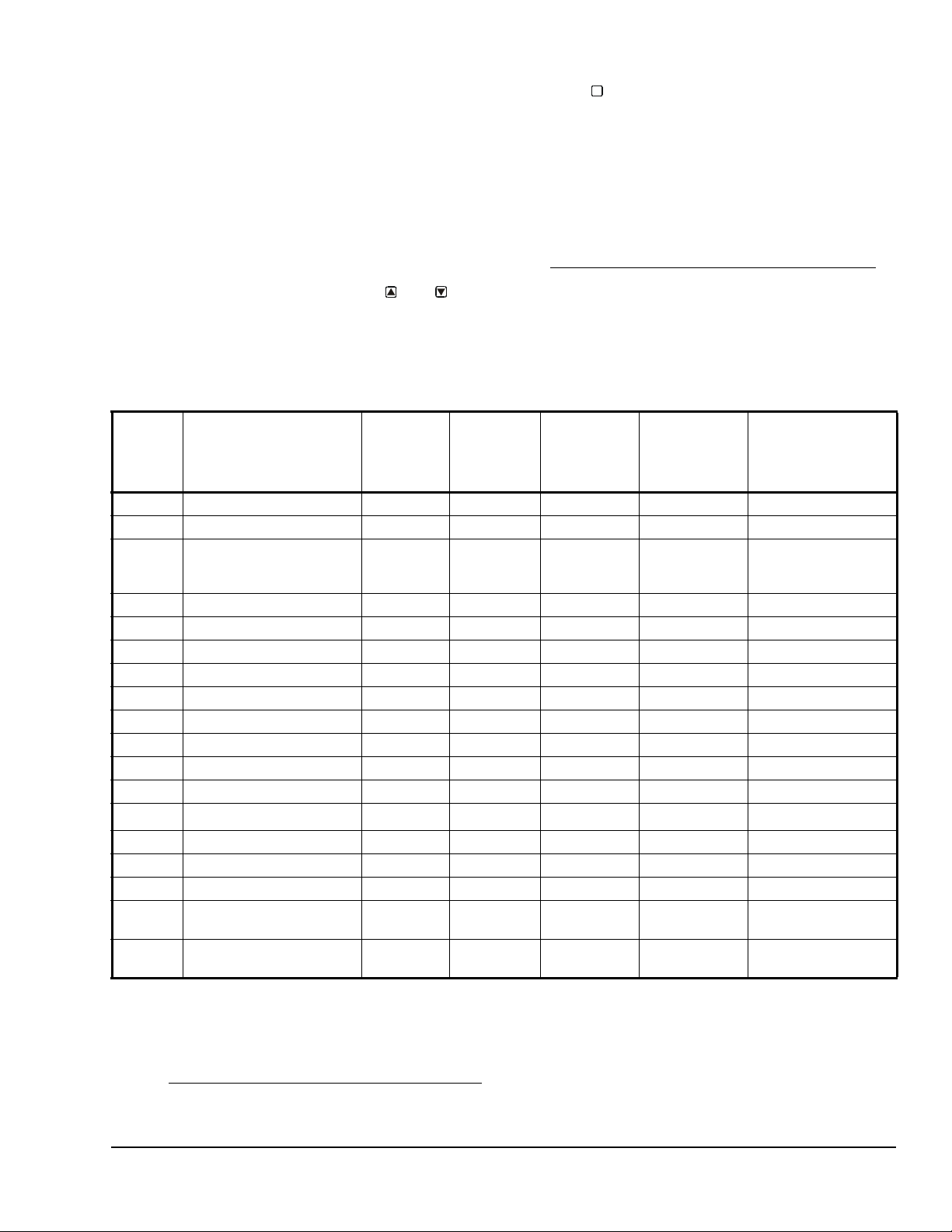
Table 3: System 450 Sensor Types, Setup Values, and Sensor/Transducer Product Codes
Sensor
Type
Unit of Measurement
Value
(Condition/Units)
Effective
Sensing
Range
Range of
Usable
Values
1
Resolution
Increment
Value
Minimum
Proportional
or Control
Sensor Product
Type Number
Band
°F °F (Temperature/degrees) -46 to 255 -40 to 250 1 1 A99B-xxx
°C °C (Temperature/degrees) -43 to 124 -40 to 121 0.5 0.5 A99B-xxx
rH % (Humidity/%RH) 1 to 100 10 to 95 1 2 HE-67Sx-xxxxx
P 0.5 INWC (Pressure/in. W.C.) 0 to 0.5 0.025 to 0.5 0.005 0.025 DPT2650-0R5D-AB
P 2.5 INWC (Pressure/in. W.C.) 0 to 2.5 0.1 to 2.5 0.02 0.1 DPT2650-2R5D-AB
P 5 INWC (Pressure/in. W.C.) 0 to 5.0 0.25 to 5.0 0.05 0.25 DPT2650-005D-AB
P 8 bAR (Pressure/bar) -1 to 8 -1 to 8 0.05 0.1 P499Rxx-401C
P 10 INWC (Pressure/in. W.C.) 0 to 10 0.5 to 10 0.05 0.2 DPT2650-10D-AB
P 15 bAR (Pressure/bar) -1 to 15 -1 to 15 0.1 0.2 P499Rxx-402C
P 30 bAR (Pressure/bar) 0 to 30 0 to 30 0.1 0.4 P499Rxx-404C
P 50 bAR (Pressure/bar) 0 to 50 0 to 50 0.2 0.4 P499Rxx-405C
P100 PSI (Pressure/psi) 0 to 100 0 to 100 0.5 1 P499Rxx-101C
3
P110
P200 PSI (Pressure/psi) 0 to 200 0 to 200 1 1 P499Rxx-102C
P500 PSI (Pressure/psi) 0 to 500 90 to 500 1 5 P499Rxx-105C
P750 PSI (Pressure/psi) 0 to 750 150 to 750 2 6 P499Rxx-107C
HI°F °F (Temperature/degrees) -50 to 340
HI°C °C (Temperature/degrees) -45.5 to
Hg/PSI (Pressure/Hg-psi) -10 to 100 -10 to 100 0.5 1 P499Rxx-100C
4
1 1 TE-631x, TE-6000-x
4
0.5 0.5 TE-631x, TE-6000-x
170
-40 to 340
-40 to 170
HE-67Nx-xxxxx
HE-68Nx-0N00WS
TE-68NT-0N00S
TE-68NT-0N00S
2
1. Because of the way that the System 450 Differential Sensor (Sn-d) is set up and calculated with two identical sensors (Sn1 and Sn-2), the Range of Usable Values is twice as large as a single sensor. Each Sensor Type has an equal number of
positive and negative values. See Table 9 for the Range of Usable Values when an output references Sn-d.
2. Refer to the System 450 Series Modular Controls Product Bulletin (LIT-12011458), Catalog Page (LIT-1900549), or
Technical Bulletin (LIT-120114 59) for additional ordering information for System 450 compatible sensors and transducers.
3. See Setting Up Outputs
reference the P110 Sensor Type.
That Reference a P110 Sensor on page 9 for information on setting up System 450 outputs that
System 450™ Series Control Modules with Relay Outputs Installation Instructions 7
Page 8
4. Many of the 1,000 ohm Nickel temperature sensors that can be set up as HI°F or HI°C Sensor Types are not designed for
SENS
-- -
P500
Sn-1
°F
Sn-2
--
Sn-3
-3
OFFS
use across the entire Range of Usable Values for HI°F and HI°C Sensor Types. Refer to the Technical Specifications
sections in the TE-6000 Series Temperature Sensing Elements Product Bulletin (LIT-216288), the TE-6300 Series
Temperature Sensors Product Bulletin (LIT-216320), and the TE-6800 Series Temperature Sensor Product Bulletin
(LIT-12011542) to determine the temperature range that the various 1,000 ohm Nickel temperature sensors are specified to
operate in.
T ab le 4 provides sensor setup information, procedures,
and example screens. Figure 7 on page 21 provides a
System 450 UI setup example.
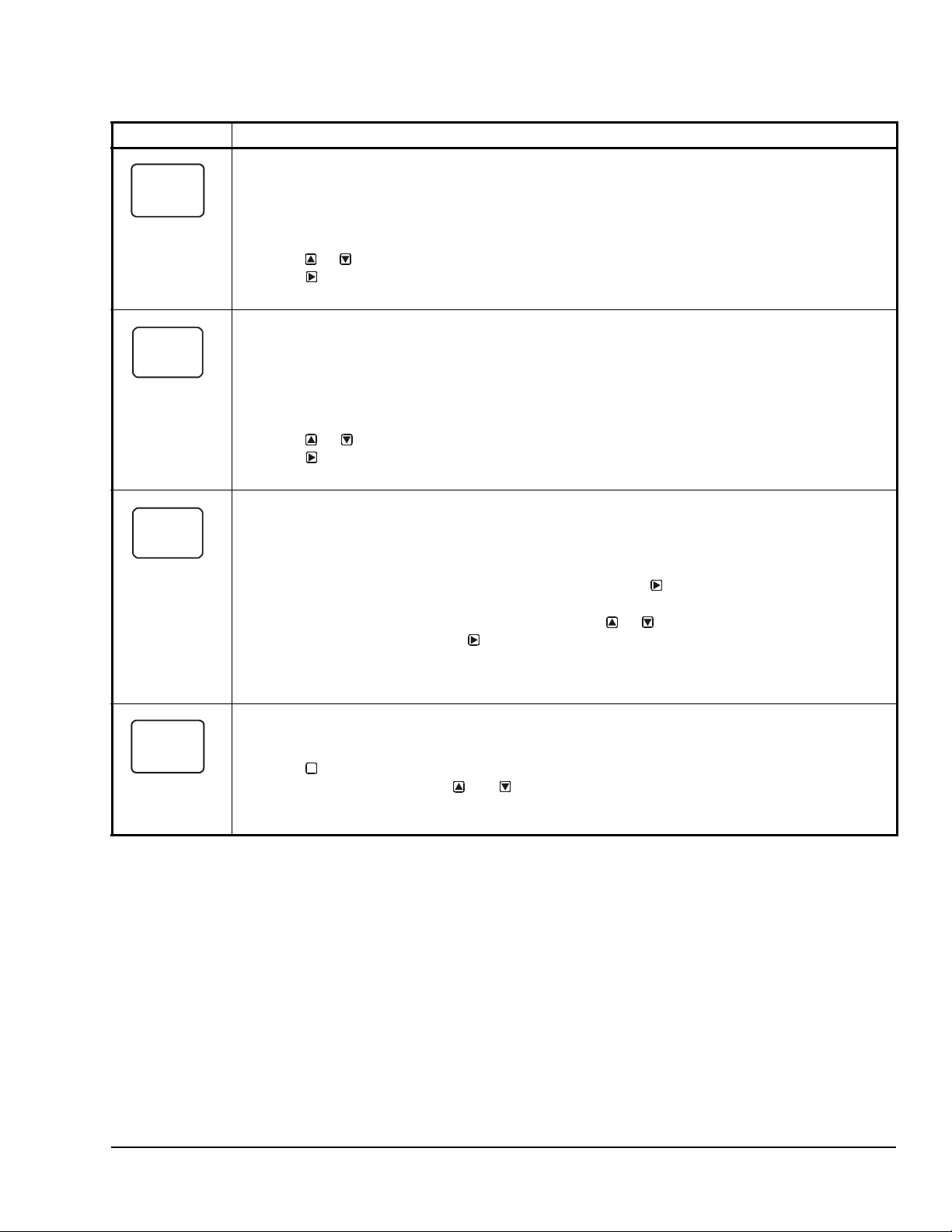
Table 4: System 450 Sensor Setup Screen Information and Procedures (Part 1 of 2)
LCD Screen Name, Description/Function, User Action, and Example
Sensor Setup Start Screen: The Sensor Setup Start screen is the first screen displayed when you
access the System 450 setup screens. From the Sensor Setup Start screen you can navigate to the
Output Setup Start screens or the Sensor Setup screens. See Figure 7.
Note: You must set up the input sensors before you can set up the control system outputs. The Sensor
Setup Start screen is view-only; selections are not made in Setup Start screens.
1. In the Sensor Setup Start screen, press
(Sn-1) and begin setting up the sensors in your control system.
The screen example shows the Sensors Setup Start screen with flashing dashes.
Sensor Type Selection Screens: The Sensor Type you select for an input sensor automatically
determines the setup parameters and values for each output that is set up to reference that sensor. See
Table 3 for information about System 450 sensors/transducers, Sensor Types, condition type, units of
measurement, minimum control band or proportional band, setup values, value ranges, and product code
numbers.
Note: For outputs to operate properly, the selected Sensor Type must match the sensor/transducer
model wired to the control module, and the sensor/transducer must be wired to the proper control module
input terminals.
2. In the Sn-1 Sensor Type Selection screen, press or to select the desired Sensor Type.
Press
3. In the Sn-2 Sensor Type Selection screen, press or to select the desired Sensor Type.
Press to save your selection and go to the Sn-3 Sensor Type Selection screen.
Note: If your control system does not use three input sensors, simply press
flashing in a Sensor Type Selection screen to save no Sensor Type and go to the next setup screen.
4. In the Sn-3 Sensor Type Selection screen, press or to select the desired Sensor Type.
Press
• go to the Temperature Offset Setup screen for the first temperature sensor in your system.
• return to the Sensor Setup Start Screen, if your control system has no temperature sensors.
Note: Beginning with firmware Version 2.00, if you select the same Sensor Type for Sn-1 and Sn-2, two
additional functional sensors (Sn-d and HI-2) are available for selection when you set up the control
system outputs. If you select the same Sensor Type for Sn-1, Sn-2 and Sn-3, then functional sensor HI-3
is also available for selection when you set up outputs. See High Input-Signal Selection
Differential Control
The screen examples show Sn-1 with the P500 Sensor Type selected; Sn-2 with the °F Sensor Type
selected; and Sn-3 with the no Sensor Type selected.
T emperature Offset Selection Screens: Select a temperature offset for the temperature inputs (only) in
your control system.
2
Sensor Type °F enables an offset of +/- 5°F in 1 degree increments.
Sensor Type °C enables an offset of +/- 2.5°C in 0.5 degree increments.
Note: The temperature offset changes the displayed temperature value by the selected offset value.
5. Press or to select the desired temperature offset value. Press :
• to go to the next Temperature Offset Selection screen (if there are additional temperature
sensors in your control system) and repeat this step for each temperature sensor.
• to return to the Sensor Setup Start screen.
The screen example shows an OFFS value of -3 (°F) for Sensor 2. Therefore a sensed temperature value
of 75 (°F) at Sensor 2 is displayed as 72 (°F).
to save your selection and go to the Sn-2 Sensor Type Selection screen.
to save your selection and either:
on page 16 for more information.
to go to the first Sensor Type Selection screen
while the two dashes are
on page 9 and
System 450™ Series Control Modules with Relay Outputs Installation Instructions8
Page 9
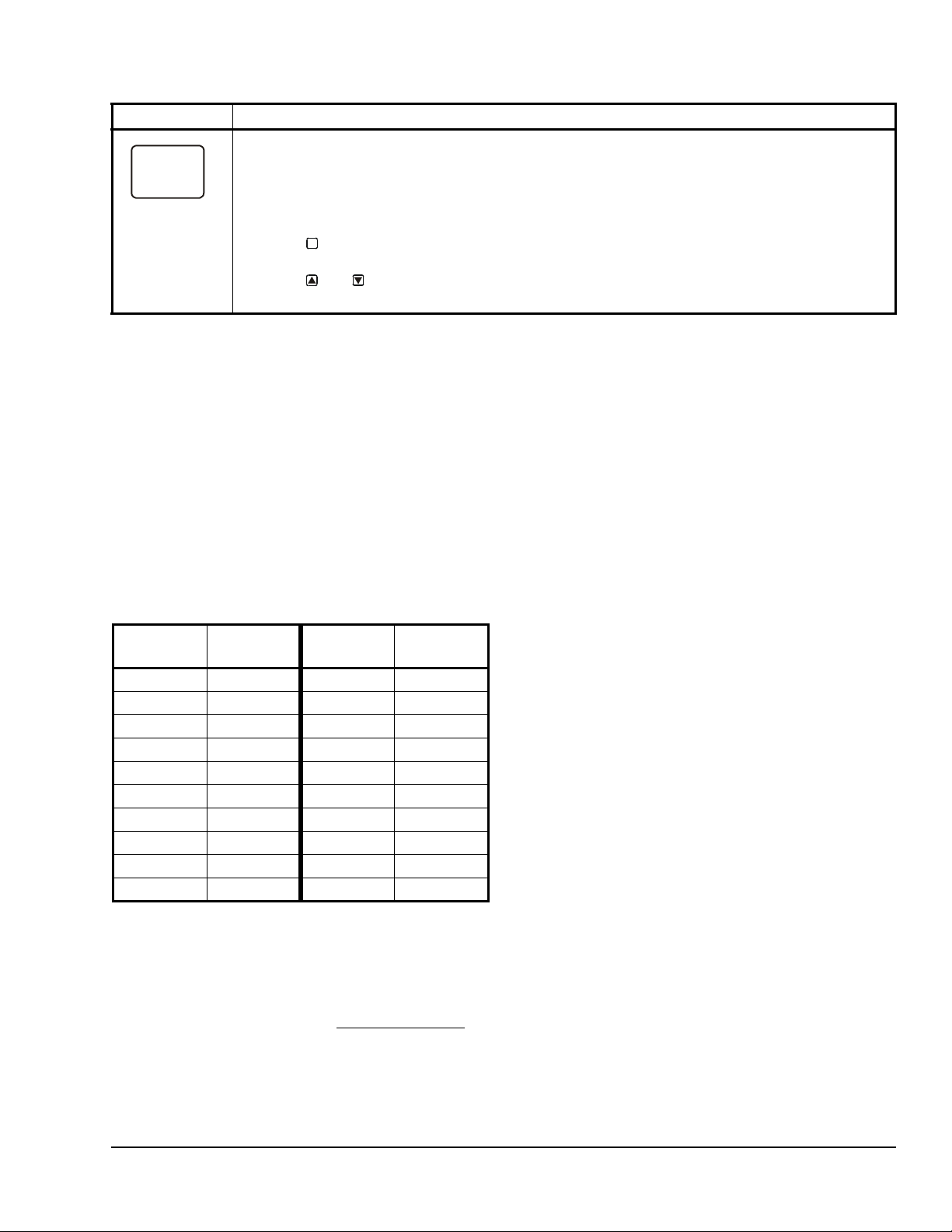
Table 4: System 450 Sensor Setup Screen Information and Procedures (Part 2 of 2)
SENS
-- -
LCD Screen Name, Description/Function, User Action, and Example
Sensor Setup Start Screen: When you have finished setting up all of the sensors for your control
system, the display returns to the Sensor Setup Start screen.
Note: Y ou can edit the sensor set up values at any time, if required. However, changing the Sensor Type
for a sensor that is referenced by an output requires setting up the output again to the new Sensor Type
values.
After the sensors are set up for your control system, you can:
• Press to scroll through the Output Setup Start sc ree n s and begin setting up your system
• Press and simultaneously to return to the Main screens.
The screen example shows Sensors Setup Start screen with flashing dashes.
M
outputs.
Setting Up Outputs That Reference a P110 Sensor
The P110 Sensor Type can monitor negative pressure
down to 20 InHg (-10 psi). When referencing a P110
sensor, System 450 displays negative pressure values
in InHg on the Main and System Status screens.
But when you set up an output that references a P110
sensor and the setup value is a negative pressure
value, you must select a pressure value in negative psi.
Use Table 5 to determine the negative PSI setup value
that corresponds to your InHg target value. For
example, if you want a relay output to go off when the
sensed pressure reaches 7 InHg, you select the value
-3.5 (psi) in the output’s Relay OFF Selection screen.
Table 5: InHg Target Values/PSI Setup Values
InHg
Value
1 -0.5 11 -5.5
2 -1.0 12 -6.0
3 -1.5 13 -6.5
4 -2.0 14 -7.0
5 -2.5 15 -7.5
6 -3.0 16 -8.0
7 -3.5 17 -8.5
8 -4.0 18 -9.0
9 -4.5 19 -9.5
10 -5.0 20 -10.0
psi Setup
Value
InHg
Value
psi Setup
Value
Note: When an output references the P110 Sensor
Type and the output is set up for Differential Control
(Sn-1 and Sn-2 are P110 Sensor Type), the negative
pressure values displayed in the differential pressure
System Status screen (dIFP) are displayed as negative
psi values, not InHg values. See Differential Control
on
page 16 for more information.
High Input-Signal Selection
Beginning with firmware V ersion 2.00, standard System
450 control modules include the High Input-Signal
Selection control capability.
The High Input-Signal Selection feature enables a
System 450 control system to monitor a condition
(temperature, pressure, or humidity) with two or three
sensors (of the same type) and control relay and/or
analog outputs based on the highest condition value
sensed by the two or three referenced sensors.
In two sensor applications (HI-2), Sn-1 and Sn-2 must
be the same Sensor Type. In three sensor applications
(HI-3), Sn-1, Sn-2, and Sn-3 must be the same Sensor
Type.
A System 450 control system, using High Input-Signal
Selection, can monitor the outlet pressures of two
condenser coils in a multi-circuit condensing unit using
two pressure sensors of the same type; one connected
to each coil outlet.
If the multi-circuit condensing unit has single speed fan
motors, multiple relay outputs can be set up to
reference the high input-signal and System 450 can
stage the fans on and off based on the pressure
sensed at the coil with the highest pressure.
If the multi-circuit condensing unit has variable speed
fan motors, one or more analog outputs can be set up
to reference the high input-signal and control the fan
motor speeds based on the pressure sensed at the coil
with the highest pressure.
System 450™ Series Control Modules with Relay Outputs Installation Instructions 9
Page 10

Setting Up System 450 Outputs
OUTR
1
-- -
SENS
SENS
Sn-d
SENS
1
HI-2
SENS
1
After you build and connect power to your control
system module assembly, the output numbers and
output types for your control system are auto m at ica lly
assigned in the UI.
Note: You must set up the input sensors for your
control system before you can set up the outputs. See
Setting Up System 450 Sensors
information.
To set up System 450 outputs in the UI:
1. Apply power to your module assembly. After the
Startup screen appears briefly (displaying the
control module firmware version), the Main screen
appears on the LCD.
2. In the Main screen, press and hold
simultaneously for 5 seconds to access the setup
screens and to go to the Sensor Setup Start
screen.
3. At the Sensor Setup Start screen, press
repeatedly to scroll through and select the desired
Output Setup Start screen. The Output Setup
Start screen indicates the output number and the
output type for the selected output.
on page 7 for more
and
M
4. To set up standard Relay Outputs and Relay
Outputs with High Input-Signal Selection, see
Setting
High Input-Signal Selection Control and T able6 for
setup information and procedures.
5. For standard Analog Outputs and Analog Outputs
with High Input-Signal Selection, see S
Analog Output for Standard Control or High InputSignal Selection Control and Table 8 for setup
information and procedures.
6. For Relay Outputs with Differential Control, see
Setting
page 16 and Table 10.
7. For Analog Outputs with Differential Control, see
Setting
page 16 and Table 11.
Setting Up a Relay Output for Standard Control or High Input-Signal Selection Control
Table 6 provides information, procedures, guidelines,
and screen examples for setting up relay output s for
standard or High Input-Signal Selection control. Se e
Figure 7 on page 21 for example menu flow of the
Relay Output 1 set up in Table 6.
Up a Relay Output for Standard Control or
etting Up an
Up an Output for Differential Control on
Up an Output for Differential Control on
Table 6: System 450 Setup Screen Information and Procedures for Relay Outputs with Standard Control
and High Input-Signal Selection Control (Part 1 of 3)
LCD Screen Name, Description/Function, User Action, and Example
Relay Output Setup Star t Scr e en: The output numbers and the output type (relay or analog ) are
determined by the module types and configuration of your control system’s module assembly and are
automatically assigned when you connect power to the module assembly. (See Setting Up a Control
System in the User Interface on page 5.)
Note: You must set up the control system input sensors before you can set up the outputs.
--
Sn-2
1. In the Relay Output Setup Start screen, press
The screen example shows a Relay Output Setup Start screen for Output 1.
Sensor Selection Screen: The sensor you select here determines the output’s setup parameters and
values, including condition type, unit of measurement, minimum control band, default setup values, and
setup value ranges for several of the remaining output setup screens. If a sensor is not selected, the
remaining output setup screens do not appear. If a sensor is already selected for this output, the Sensor
Selection screen does not appear here and the Relay ON Selection (ON or dON) screen appears instead.
Note: Y ou must select a sensor in this Sensor Selection screen and the selected sensor must be already
set up in the System 450 UI. (See Setting Up System 450 Sensors
Note: Beginning with firmware Version 2.00, the functional sensors Sn-d and HI-2 are available, if Sn-1
and Sn-2 are the same Sensor Type. If Sn-1, Sn-2, and Sn-3 are the same Sensor Type, the functional
sensor HI-3 is also available.
2. Press or to select the sensor that this output references:
• For standard control action, select Sn-1, Sn-2, or Sn-3.
• For standard control action with High Input-Signal Selection, select HI-2 or HI-3.
Then press
Note: For Differential Control, select Sn-d and go to Table 10 on page 17 for information, procedures,
guidelines, and screen examples for setting up outputs for Differential Control.
The top screen example shows the initial Sensor Selection screen for Relay Output 1 before a sensor is
selected. The remaining screen examples show some of the sensors that may be available for selection.
For the Output Relay example, Sn-2 is selected as the Sensor for Output 1 as shown in the second
screen.
to save your sensor selection and go to the Relay ON Selection screen.
to go to the output’ s Sensor Se lection scre en.
.)
System 450™ Series Control Modules with Relay Outputs Installation Instructions10
Page 11

Table 6: System 450 Setup Screen Information and Procedures for Relay Outputs with Standard Control
ON
1
78
OFF
1
ONT
1
0
OFFT
1
120
SNF
1
OFF
SENS
and High Input-Signal Selection Control (Part 2 of 3)
LCD Screen Name, Description/Function, User Action, and Example
Relay ON Selection Screen: Select the value at which the relay turns On. Relay ON is defined as relay
LED On/Lit, relay contacts N.O. to C are closed, and N.C. to C contacts are open.
Note: The value ranges and minimum control band are determined by the Sensor Type selected for the
sensor that the output references and are enforced in the Relay ON and Relay OFF Selection screens.
Sn-2
3. Press or to select the value at which the output relay turns On, then press
selection and go to Relay OFF Selection screen.
The screen example shows an ON value of 78 (°F) selected for Relay Output 1.
Relay OFF Selection Screen: Select the value at which the relay turns Off. Relay OFF is defined as
relay LED Off, relay contacts N.C. to C are closed, and N.O. to C contacts are open.
Note: The value ranges and minimum control band are determined by the Sensor Type selected for the
sensor that the output references and are enforced in the Relay ON and Relay OFF Selection screens.
4. Press or to select the value at which output relay turns Off, then press
selection and go to Minimum Relay ON TIme Selection scree n.
The screen example shows an OFF value of 75 (°F) selected for Relay Output 1.
Minimum Relay ON Time Selection Screen: Minimum ON T ime range is 0 to 300 seconds.
5. Press or to select the minimum time that the output relay remains On after reaching the
Relay ON value, then press
Selection screen.
Screen example shows an ONT value of 0 (seconds) selected for Output 1.
Minimum Relay OFF Time Selection Screen: Minimum OFF Time range is 0 to 300 seconds.
6. Press or to select the minimum time that this output relay remains Off after reaching the
Relay OFF value. Press
screen.
The screen example shows an OFFT value of 120 (seconds) selected for Output 1.
Sensor Failure Mode Selection Screen: Select the output’s mode of operation if a referenced sensor or
sensor wiring fails. If the output references functional sensors HI-2 or HI-3, the output enters the Sensor
Failure mode whenever a referenced sensor or sensor wiring fails. The output operates in the selected
Sensor Failure mode until the failure is remedied. Sensor Failure mode selections for Relay Outputs
include:
• ON = Output relay remains On during sensor failure.
• OFF = Output relay remains Off during sensor failure.
7. Press or to select this output’s mode of operation if the sensor or sensor wiring fails.
Press
The screen example shows OFF selected as the Sensor Failure mode for Output 1.
Edit Sensor Screen: This screen displays the sensor that this output currently references. Typically, no
action is taken in this screen. But if you need to change the sensor that this output references, you can
select a different sensor for this output in this screen.
Note: If you change the sensor that an output references to a sensor with a different Sensor Type, the
default setup values for the output change, and you must set the output up again.
8. If you do not need to change this output’s sensor, simply press to save the current sensor
selection and return to the Relay Output Setup Start screen.
To change the sensor this output references, press or to select the new sensor that this
output references. Then press to save the new sensor selection and return to the Relay ON
Selection screen (ON or dON). If the new sensor has a different Sensor Type from the
previously referenced sensor, repeat the output setup procedure for this output.
This Relay Output is now set up in the System 450 UI.
The screen example shows Sn-2 is selected Sensor for Output 1.
to save your sensor failure mode selection and go to the Edit Sensor screen.
to save your selection and go to the Minimum Relay OFF Time
to save your selection and go to the Sensor Failure Mode Selection
to save your
to save your
System 450™ Series Control Modules with Relay Outputs Installation Instructions 11
Page 12

Table 6: System 450 Setup Screen Information and Procedures for Relay Outputs with Standard Control
OUTR
1
-- -
0%
100%
Less Greater
65°F
10%
70°F
SP > EP
SP = 70 ( )
EP = 65 ( )
OSP = 10 (%)
°F
°F
OSP < OEP
OEP
Band
Fig:sys450_c ntrl_rmp_exmpl
Figure 6: Control Ramp Example for a Typical
Heating Application (SP > EP and OSP < OEP)
and High Input-Signal Selection Control (Part 3 of 3)
LCD Screen Name, Description/Function, User Action, and Example
Relay Output Setup Start Screen
After you have set up this Relay Output, you can go to another Output Setup Start screen, the Sensor
Setup Start screen, or return to the Main screens.
9. Press to scroll through the remaining Output Setup Start screens and return to the Sensor
The screen example shows a Relay Output Setup Start screen for Output 1.
M
Setup Start screen, or press and simultaneously to return to the System 450 Main
screens.
Setting Up an Analog Output for Standard Control or High Input-Signal Selection Control
Analog outputs provide an analog signal to control
equipment in you application based on the input from a
standard fixed setpoint sensor (Sn-1, Sn-2, or Sn-3) or
a High Input Signal Selection sensor (HI-2 or HI-3).
Note: The differential sensor, Sn-d, is used to set up
analog and relay outputs for Differential Control. See
Setting
Up an Output for Differential Control on page
16 for more information.
Analog outputs provide an auto-selecting analog sign al
that is proportional to the sensed input condition. The
System 450 analog output senses the impedance of
the controlled equipment’s analog input circuit and
automatically delivers either a 0–10 VDC or 4–20 mA
signal to the controlled equipment.
Figure 6 shows an example of the analog output setup
values and the resulting output signal in a typical spac e
heating application (SP > EP and OSP < OEP).
Proportional
EP
SP
System Output
OSP
Condition Value
OEP = 10 0 ( % )
The control action between the input signal and the
output signal can be set up four ways, depending on
the values selected for the Setpoint (SP), End Point
(EP), Percent Output Signal Strength at Setpoint
(OSP), and Percent Output Signal Strength at End
Point (OEP). The LCD displays different Control Ramp
icons for the four control actions.
System 450™ Series Control Modules with Relay Outputs Installation Instructions12
Page 13

Ta ble 7 shows the four Control Ramp icons and the
P
r
o
p
o
r
t
i
o
n
B
a
n
d
OEP=100%
OSP=0%
F
P
r
o
p
o
r
t
i
o
n
a
l
B
a
n
d
OEP=100%
OSP=0%
OSP=100%
OEP=0%
OSP=100%
OEP=0%
P
r
o
p
o
r
t
i
o
n
a
l
B
a
n
d
associated analog output setup value relationships.
Table 7: Analog Output Control Ramp Icons
Control Ramp
Displayed on
LCD
Control Action Set the Analog Output Value
Relationships for the Desired Control
Action and Corresponding Control
Ramp
SP < EP
OSP < OEP
Output Minimum at SP
SP=50°F EP=60°
l
a
SP > EP
Output Minimum at SP
EP=50°F SP=60°F
OSP < OEP
SP > EP
OSP > OEP
Output Maximum at SP
EP=50°F SP= 60°F
l
a
n
o
i
t
r
d
o
n
p
a
o
r
B
P
SP < EP
OSP > OEP
Output Maximum at SP
SP=50°F EP=60°F
Table 8 provides information, procedures, guidelines,
and screen examples for setting up analog outputs that
reference standard or High Input-Signal Selection
sensors. See Figure 7 on page 21 for example menu
flow of the Analog Output 3 set up in Table 8.
System 450™ Series Control Modules with Relay Outputs Installation Instructions 13
Page 14

T able 8: System 450 Setup Screen Information and Procedures for Analog Output with St andard and High
OUTA
3
-- -
SENS
SENS
Sn-d
SENS
3
HI-2
SENS
3
SP
3
200
EP
3
250
OSP
3
10
OEP
3
90
Input-Signal Selection Control (Part 1 of 2)
LCD Screen Name, Description/Function, User Action, Example
Analog Output Setup Start Screen: The output numbers and the output type (relay or analog) are
determined by the module types and configuration of your control system’s module assembly and are
automatically assigned when you connect power to the module assembly. (See Setting Up a Control
System in the User Interface on page 5.)
Note: You must set up the system’s sensors before you can set up the outputs.
--
Sn-1
1. Press
The screen example shows the Analog Output Setup Start screen for Output 3.
Sensor Selection Screen: The sensor you select here determines this output’s setup parameters and
values, including condition type, unit of measurement, minimum proportional band, default setup values,
and setup value ranges for several of the remaining output setup screens. If a sensor is not selected here,
this output’s remaining setup screens do not appear. If a sensor is already selected for this output, the
Sensor Selection screen does not appear here, and the Setpoint Selection (SP or dSP) screen appears
instead.
Note: You must select a sensor in this Sensor Selection screen and the selected sensor must be already
set up in the System 450 UI. (See Setting Up System 450 Sensors
Note: Beginning with firmware Version 2.00, the functional sensors Sn-d and HI-2 are available if Sn-1
and Sn-2 are the same Sensor Type. If Sn-1, Sn-2, and Sn-3 are the same Sensor Type, the functional
sensor HI-3 is also available.
2. Press or to select the sensor that this output references:
• For standard control ac t io n, select Sn-1, Sn-2, or Sn-3.
• For standard control action with High Input-Signal Selection, select HI-2 or HI-3.
Then press
Note: For Differential Control, select Sn-d and go to Table 11 on page 18 for information, procedures,
guidelines, and screen examples for setting up an Analog Output for Differential Control.
The top screen example shows the initial Sensor Selection screen for Analog Output 3 before a sensor is
selected. The remaining screen examples show some of the sensors that may be available for selection.
For the Analog Output example, Sn-1 is the selected Sensor for Output 3 as shown in the second screen.
Setpoint Selection Screen: Setpoint is the target value that the controlled system drives towards and
along with End Point, defines this output’s proportional band.
Note: An output’s minimum proportional band (between Setpoint and End Point) is automatically
enforced in the output’s Setpoint and End Point Selection screens.
3. Press or to select this output’s Setpoint value. Press
selection and go to the End Point Selection screen.
The screen example shows a SP value of 200 (psi) selected for Output 3.
End Point Selection Screen: End Point is the (condition) value that the controlled system drives away
from (towards Setpoint) and, along with Setpoint, defines this output’s proportional band.
Note: An output’s proportional band (between Setpoint and End Point) is automatically enforced in the
output’s Setpoint and End Point Selection screens.
4. Press or to select this output’s End Point value. Press
selection and go to the %Output Signal Strength at Setpoint Selection screen.
The screen example shows an EP value of 250 (psi) selected for Output 3.
Output Signal Strength at Setpoint Selection Screen: Select the strength of the signal that this output
generates when the sensed condition is at the Setpoint value. The signal strength range is 0 to 100 (%).
5. Press or to select this output’ s %Output Signal Strength at Setpoint (OSP) value. Press
to save your selection and go to the %Output Signal Strength at End Point Selection screen.
The screen example shows an OSP value of 10 (%) selected for Output 3. Therefore Output 3 generates
10% of the total signal strength (1 V or 5.6 mA) when the input is at the Setpoint value of 200 (psi).
Output Signal Strength at End Point Selection Screen: Select the strength of the signal that this output
generates when the sensed condition is at the End Point value. The signal strength range is 0 to 100 (%).
6. Press or to select this output’s %Output Signal Strength at End Point value. Press
save your selection and go to the Integration Constant Selection screen.
The screen example shows an OEP value of 90 (%) selected for Output 3. Therefore Output 3 generates
90% of the total signal strength (9 V or 18.4 mA) when the input is at the End Point value of 250 (psi).
to go to this output’s Sensor Selection screen.
.)
to save your sensor selection and go to the Setpoint Selection screen.
to save your Setpoint value
to save your End Point value
to
System 450™ Series Control Modules with Relay Outputs Installation Instructions14
Page 15
T able 8: System 450 Setup Screen Information and Procedures for Analog Output with St andard and High
I-C
3
0
SNF
3
OFF
SENS
3
Sn-2
OUTA
3
-- -
Input-Signal Selection Control (Part 2 of 2)
LCD Screen Name, Description/Function, User Action, Example
Integration Constant Selection Screen: An integration constant allows you to set up proportional plus
integral control for this analog output. proportional plus integral control can drive the load cl oser to
Setpoint than proportional only control.
Note: Initially, you should select the I-C value of 0 (zero) for no integration constant. Refer to the System
450 Series Technical Bulletin (LIT-12011459) for more information on proportional plus integral control
and setting an integration constant in the System 450 UI.
7. Press or to select this output’s Integration Constant for proportional plus integral control.
Press
The screen example shows an I-C value of 0 (zero) selected for Output 3.
Sensor Failure Mode Selection Screen: Select the output’s mode of operation if a referenced sensor or
sensor wiring fails. If the output references functional sensors HI-2 or HI-3, the output enters the Sensor
Failure mode whenever one of the referenced sensors or sensor wiring fails. The output operates in the
selected Sensor Failure mode until the failure is remedied. Sensor Failure mode selectio ns for Analog
Outputs include:
• ON = Output generates the selected OEP signal strength during sensor failure.
• OFF = Output generates the selected OSP signal strength during sensor failure.
8. Press or to select this output’s mode of operation if the sensor or sensor wiring fails.
Press to save your selection and go to the Edit Sensor Selection screen.
The screen example shows OFF selected as the Sensor Failure mode for Output 3.
Edit Sensor Selection Screen: This screen displays the sensor that this output currently references.
Typically, no action is taken in this screen. But if you need to change the sensor that this output
references, you can select a different sensor for this output in this screen.
Note: If you change the sensor that an output references to a sensor with a different Sensor Type, the
default setup values for the output change, and you must set the output up again.
9. If you are not changing this output’s sensor, simply press to save the current sensor
selection and return to the Analog Output Setup Start screen.
To change the sensor this output references, press or to select the new sensor that this
output references. Then press to save the new sensor selection and return to the Setpoint
Selection screen (SP or dSP). If the new sensor has a different Sensor Type from the previously
referenced sensor, repeat the output setup procedure for this output.
The screen example shows Sn-2 as the selected Sensor for Output 3.
Analog Output Setup Start Screen
After you have set up this Analog Output, you can go to another Output Setup Start screen, the Sensor
Setup Start screen, or return to the Main screens.
10. Press to scroll through the remaining Output Setup Start screens and return to the Sensor
Setup Start screen, or press and simultaneously to return to the System 450 Ma in
screens.
The screen example shows the Analog Output Setup Start screen for Output 3.
to save your selection and go to the Sensor Failure Mode Selection screen.
M
System 450™ Series Control Modules with Relay Outputs Installation Instructions 15
Page 16

Differential Control
Beginning with V ersion 2.00 firmware, standard System
450 control modules include Differential Control
capability. Differential control is used to monitor and/or
maintain a given difference in a condition (temperature,
pressure, or humidity) between two sen so r po ints
within a system, process, or space.
The Differential Control feature enables a System 450
control system to monitor the temperature, pressure, or
humidity differential between two sensors of the same
type (Sn-1 and Sn-2) and control relay and/or analog
outputs based on the sensed differential value relative
to user-selected differential values (dON, dOFF, dSP,
and dEP).
When a Differential Control sensor (Sn-d) is set up, the
displayed differential sensor value is a calculated
variable value; (Sn-d) = (Sn-1) – (Sn-2).
Note: The System 450 Differential Control sensor
(Sn-d) value is always equal to Sn-1 minus Sn-2.
Therefore, depending on the intended control action of
the output, the differential value may be either a
positive or negative value.
The Sn-d value is displayed in the System S tatus
screens as either a temperature differentia l value
(dIFT), pressure differential value (dIFP), or humidity
differential value (dIFH). The unit of measurement
associated with the displayed differential value is
determined by the Sn-1 and Sn-2 Sensor Type. See
Table 3 on page 7 for Sensor Types and their units of
measurement.
The relay output setup values dON and dOFF are also
condition differential values.
• When a relay output is set up for differential
control, System 450 controls the relay state (On or
Off) based on the difference between Sn-1 and
Sn-2 (Sn-d) relative to the user-selected dif ferential
On (dON) and differential Off (dOFF) values.
• When an analog output is set up for differential
control, System 450 controls the analog signal
strength (0 to 100%) based on the difference
between Sn-1 and Sn-2 (Sn-d) relative to the userselected differential setpoint (dSP) and differential
endpoint (dEP) values.
Differential Sensor Failure Mode
Any output set up to reference the Differential Sensor
(Sn-d) enters the selected Sensor Failure mode when
either Sn-1 sensor, Sn-2 sensor, or the sensor wiring
fails.
Differential Sensor Range of Usable Values
Because of the way that the System 450 Differential
Sensor (Sn-d) is set up and calculated with two
identical sensors (Sn-1 and Sn-2), the Range of Usable
Values is twice as large as a single sensor. Each
Sensor Type has an equal number of positive and
negative values. See Table 9 for the Range of Usable
Values when an output references Sn-d.
Table 9: Ranges of Usable Values for Sensor
Types in Differential Control Applications
Sensor
Type
°F -290 to 290 P 30 -30.0 to 30.0
°C -161.0 to 161.0 P 50 -50.0 to 50.0
rH -95 to 95 P100 -100.0 to 100.0
P 0.5 -0.500 to 0.500 P110 -110.0 to 110.0
P 2.5 -2.50 to 2.50 P200 -200 to 200
P 5 -5.00 to 5.00 P500 -500 to 500
P 8 -9.00 to 9.00 P750 -750 to 750
P 10 -10.00 to 10.00 HI°F -380 to 380
P 15 -16.0 to 16.0 HI°C -210.0 to 210.0
Sn-d Range
of Usable
Values
Sensor
Type
Sn-d Range
of Usable
Values
Setting Up an Output for Differential Control
Table 10 provides information, procedures, guidelines,
and screen examples for setting up relay outputs that
reference the Differential Control sensor.
Table 11 provides information, procedures, guidelines,
and screen examples for setting up analog output s that
reference the Differential Control sensor.
Figure 8 on page 22 shows the menu flow used to set
up the output examples in Table 10 and Table 11.
System 450™ Series Control Modules with Relay Outputs Installation Instructions16
Page 17

T able 10: System 450 Setup Screen Information and Procedures for Relay Outputs with Differential Control
OUTR
1
-- -
SENS
SENS
1
1
ONT
1
0
OFFT
1
30
(Part 1 of 2)
LCD Screen Name, Description/Function, Procedures, and Example
Relay Output Setup Start Screen: The output numbers and the output type (relay or analog) are
determined by the module types and configuration of your control system’s module assembly and are
automatically assigned when you connect power to the module assembly. (See Setting Up a Control
System in the User Interface on page 5.)
Note: Y ou must set up the sy stem’s sensors before you can set up the system outputs, and you must set
up the Differential Control sensor (Sn-d) before you can set up an output with Differential Control. (See
--
Sn-d
dON
dOFF
Setting Up System 450 Sensors
1. Press to go to this output’s Sensor Selection screen.
The screen example shows the Relay Output Setup Start screen for Output 1.
Sensor Selection Screen: Selecting th e Differential Control sensor (Sn-d) here establishes this output
as a Differential Control output. Differential Control outputs have several different setup parameters and
value ranges from standard and High Input-Signal Selection outputs.
Note: To set up an output for Differential Control, the Differential Control sensor (Sn-d) must be already
set up in the System 450 UI (See Setting Up System 450 Sensors
select Sn-d in the Sensor Selection screen. If Sn-d is not selected here, the Differential Control setup
screens do not appear. If a sensor is already selected for this output, the Sensor Selection screen does
not appear here, instead the Relay ON Selection screen (ON or dON) appears.
2. Press or to select the Differential Control sensor (Sn-d) as the sensor this output
references. Press to save your sensor selection and go to the Relay dON Selection Screen.
The screen example shows Sn-d is the selected Sensor for Output 1.
Relay dON Selection Screen: Select the dON value at which the relay turns on. The dON value is a
differential value that represents the intended difference in the condition (temperature, pressure, or
humidity) between Sn-1 and Sn-2 (Sn-1 minus Sn-2) at which the relay is turned on. Depending on the
intended control action and the physical location of Sn-1 and Sn-2 sensors in the condition process, dON
may be a positive or negative value. Relay dON is defined as relay LED On/Lit, relay contacts N.O. to C
are closed, and N.C. to C contacts are open.
Note: The unit of measurement, resolution increment, minimum control band, and range of usable
values for dON and dOFF are determined by the Sensor Type selected for Sn-1 and Sn-2. (See Table 3
and Table 9 for more information.)
3. Press or to select the differential value at which the output relay turns On. Press to
save your selection and go to Relay dOFF Selection Screen.
The screen example shows a dON value of 28 (psi) selected for Relay Output 1.
Relay dOFF Selection Screen: Select the dOFF value at which the relay turns off. The dOFF value is a
differential value that represents the intended difference in the condition (temperature, pressure, or
humidity) between Sn-1 and Sn-2 (Sn-1 minus Sn-2) at which the relay is turned off. Depending on the
intended control action and the physical location of Sn-1 and Sn-2 sensors in the condition process,
dOFF may be a positive or negative value. dOFF is defined as relay LED Off, relay contacts N.C. to C are
closed, and N.O. to C contacts are open.
Note: The unit of measurement, resolution increment, minimum control band, and range of usable
values for dON and dOFF are determined by the Sensor Type selected for Sn-1 and Sn-2. (See Table 3
and Table 9 for more information.)
4. Press or to select the differential value at which output relay turns Off. Press to save
your selection and go to Minimum Relay ON TIme Selection Screen.
The screen example shows a dOFF value of 30 (psi) selected for Relay Output 1.
Minimum Relay ON Time Selection Screen: Minimum ON T ime range is 0 to 300 seconds.
5. Press or to select the minimum time that the output relay remains On after reaching the
Relay dON value. Press to save your selection and go to the Minimum Relay OFF Time
Selection Screen.
The screen example shows an ONT value of 0 (seconds) selected for Output 1.
Minimum Relay OFF Time Selection Screen: Minimum OFF Time range is 0 to 300 seconds.
6. Press or to select the minimum time that this output relay remains Off after reaching the
Relay dOFF value. Press to save your selection and go to the Sensor Failure Mode Selection
screen.
The screen example shows an OFFT value of 30 (seconds) selected for Output 1.
for information on setting up the Differential Control sensor.)
for more information.), and you must
System 450™ Series Control Modules with Relay Outputs Installation Instructions 17
Page 18

T able 10: System 450 Setup Screen Information and Procedures for Relay Outputs with Differential Control
SNF
1
OFF
SENS
OUTR
1
-- -
OUTA
2
-- -
SENS
2
Sn-d
(Part 2 of 2)
LCD Screen Name, Description/Function, Procedures, and Example
Sensor Failure Mode Selection Screen: Select the differential output’s mode of operation if either of the
referenced sensors (Sn-1 or Sn-2) or the sensor wiring fails. The ou tput operates in the selected mode
until the failure is remedied. Sensor Failure mode selections for Relay Outputs include:
• ON = Output relay remains On during sensor failure.
• OFF = Output relay remains Off during sensor failure.
7. Press or to select this output’s mode of operation if a referenced sensor or sensor wiring
fail. Press to save your sensor failure mode selection and go to the Edit Sensor Screen.
The screen example shows OFF selected as the Sensor Failure mode for Output 1.
Edit Sensor Screen: This screen displays the Differentia l Sens or (Sn - d) tha t th is ou tput currently
Sn-d
references. Typically, no action is taken in this screen. But if you need to change the sensor th at this
output references, you can select a different sensor for this output in this screen.
Note: If you change the Sn-d sensor to a different sensor, the output is no longer a Differential Control
output and you must set the output up again for the new sensor selection.
8. If you do not need to change this output’s sensor, simply press to save the current sensor
selection and return to the Relay Output Setup Start screen.
To change the sensor this output references, press or to select the new sensor that this
output references. Then press to save the new sensor selection and return to the Relay ON
Selection screen (ON or dON). If the new sensor has a different Sensor Type from the
previously referenced sensor, repeat the output setup procedure for this output.
This Relay Output is now set up in the System 450 UI.
The screen example shows Sn-d as the selected Sensor for Output 1.
Relay Output Setup Star t Scr e en: After you have set up this Relay Output, you can go to another
Output Setup Start screen, the Sensor Setup Start screen, or return to the Main screens.
9. Press to scroll through the remaining Output Setup Start screens and return to the Sensor
The screen example shows the Relay Output Setup Start screen for Output 1.
M
Setup Start screen, or press and simultaneously to return to the System 450 Main
screens.
Table 11: System 450 Setup Screen Information and Procedures for Analog Outputs with Differential
Control (Part 1 of 3)
LCD Screen Name, Description/Function, User Action, Example
Analog Output Setup Start Screen: The output numbers and the output type (relay or analog) are
determined by the module types and configuration of your control system’s module assembly and are
automatically assigned when you connect power to the module assembly. (See Setting Up a Control
System in the User Interface on page 5.)
Note: You must set up the system’s sensors before you can set up the system outputs, and you must set
up the Differential Control sensor (Sn-d) before you can set up an output with Differential Control. (See
Setting Up System 450 Sensors
1. Press
The screen example shows the Analog Output Setup Start screen for Output 2.
Sensor Selection Screen: Selecting the Differential Control sensor (Sn-d) here establishes this output as
a Differential Control output. Differential Control outputs have several different setup parameters and
value ranges from standard and High Input-Signal Selection outputs.
Note: To set up an output for Differential Control, the Differential Control sensor (Sn-d) must be already
set up in the System 450 UI (See Setting Up System 450 Sensors
select Sn-d in the Sensor Selection screen. If Sn-d is not selected here, the Differential Control setup
screens do not appear. If a sensor is already selected for this output, the Sensor Selection screen does
not appear here, instead the Setpoint Selection screen (SP or dSP) appears instead.
2. Press or to select the Differential Control sensor (Sn-d) as the sensor this output
references. Press
The screen example shows Sn-d as the selected Sensor for Output 2.
to go to this output’s Sensor Selection screen.
for information on setting up the Differential Control sensor.)
for more information.), and you must
to save your sensor selection and go to the Setpoint Selection screen.
System 450™ Series Control Modules with Relay Outputs Installation Instructions18
Page 19

Table 11: System 450 Setup Screen Information and Procedures for Analog Outputs with Differential
2
2
OSP
2
0
OEP
2
100
I-C
2
0
Control (Part 2 of 3)
LCD Screen Name, Description/Function, User Action, Example
Differential Setpoint Selection Screen: Differential Setpoint (dSP) is the target value that the controlled
30.0
dSP
25.0
dEP
system drives towards and along with Differential End Point (dEP), defines this output’s proportional band.
The dSP value is a differential value that represents a (selected) difference in the condition (temperature,
pressure, or humidity) between Sn-1 and Sn-2 (Sn-1 minus Sn-2). Depending on the intended
proportional control action and the physical location of Sn-1 and Sn-2 sensors in the condition process,
dSP may be a positive or negative value.
Note: The unit of measurement, resolution increment, minimum proportional band, and range of usable
values for dSP and dEP are determined by the Sensor Type selected for Sn-1 and Sn-2. (See T able3 and
Table 9 for more information.) The output’s minimum proportional band (between dSP and dEP) is
automatically enforced in the output’s Setpoint and End Point Selection screens.
3. Press or to select this output’s Differential Setpoint value. Press
Differential Setpoint value selection and go to the End Point Selection screen.
The screen example shows a dSP value of 25 (psi) selected for Output 2.
Differential End Point Selection Screen: Differential End Point (dEP) is the target value that the
controlled system drives towards and along with Differential Setpoint (dSP), defines this output’s
proportional band. The dEP value is a differential value that represents a (selected) difference in the
condition (temperature, pressure, or humidity) between Sn-1 and Sn-2 (Sn-1 minus Sn-2). Depending on
the intended proportional control action and the physical location of Sn-1 and Sn-2 sensors in the
condition process, dEP may be a positive or negative value.
Note: The unit of measurement, resolution increment, minimum proportional band, and range of usable
values for dSP and dEP are determined by the Sensor Type selected for Sn-1 and Sn-2. (See T able3 and
Table 9 for more information.) The output’s minimum proportional band (between dSP and dEP) is
automatically enforced in the output’s Setpoint and End Point Selection screens.
4. Press or to select this output’s Differential End Point value. Press
Differential End Point value selection and go to the %Output Signal Strength at Setpoint
Selection screen.
The screen example shows a dEP value of 30 (psi) selected for Output 2.
Output Signal Strength at Setpoint Selection Screen: Select the strength of the signal that this output
generates when the sensed condition is at the Differential Setpoint (dSP) value. The signal strength range
is 0 to 100 (%).
5. Press or to select this output’s %Output Signal Strength at Setpoint value. Press
save your selection and go to the %Output Signal Strength at End Point Selection screen.
The screen example shows an OSP value of 10 (%) selected for Output 2. Therefore Output 3 generates
10% of the total signal strength (1 V or 5.6 mA) when the input is at the Setpoint value of 200 (psi).
Output Signal Strength at End Point Selection Screen: Select the strength of the signal that this output
generates when the sensed condition is at the Differential End Point (dEP) value. The signal strength
range is 0 to 100 (%).
6. Press or to select this output’s %Output Signal Strength at End Point value. Press
save your selection and go to the Integration Con stant Selection screen.
The screen example shows an OEP value of 90 (%) selected for Output 2. Therefore Output 3 generates
90% of the total signal strength (9 V or 18.4 mA) when the input is at the End Point value of 250 (psi).
Integration Constant Selection Screen: An integration constant allows you to set up proportional plus
integral control for this analog output. proportional plus integral control can drive the load cl oser to
Setpoint than proportional only control.
Note: Initially, you should select the I-C value of 0 (zero) for no integration constant. Refer to the System
450 Series Technical Bulletin (LIT-12011459) for more information on proportional plus integral control
and setting an integration constant in the System 450 UI.
7. Press or to select this output’s Integration Constant for proportional plus integral control.
Press
The screen example shows an I-C value of 0 (zero) selected for Output 2.
to save your selection and go to the Sensor Failure Mode Selection screen.
to save your
to save your
to
to
System 450™ Series Control Modules with Relay Outputs Installation Instructions 19
Page 20
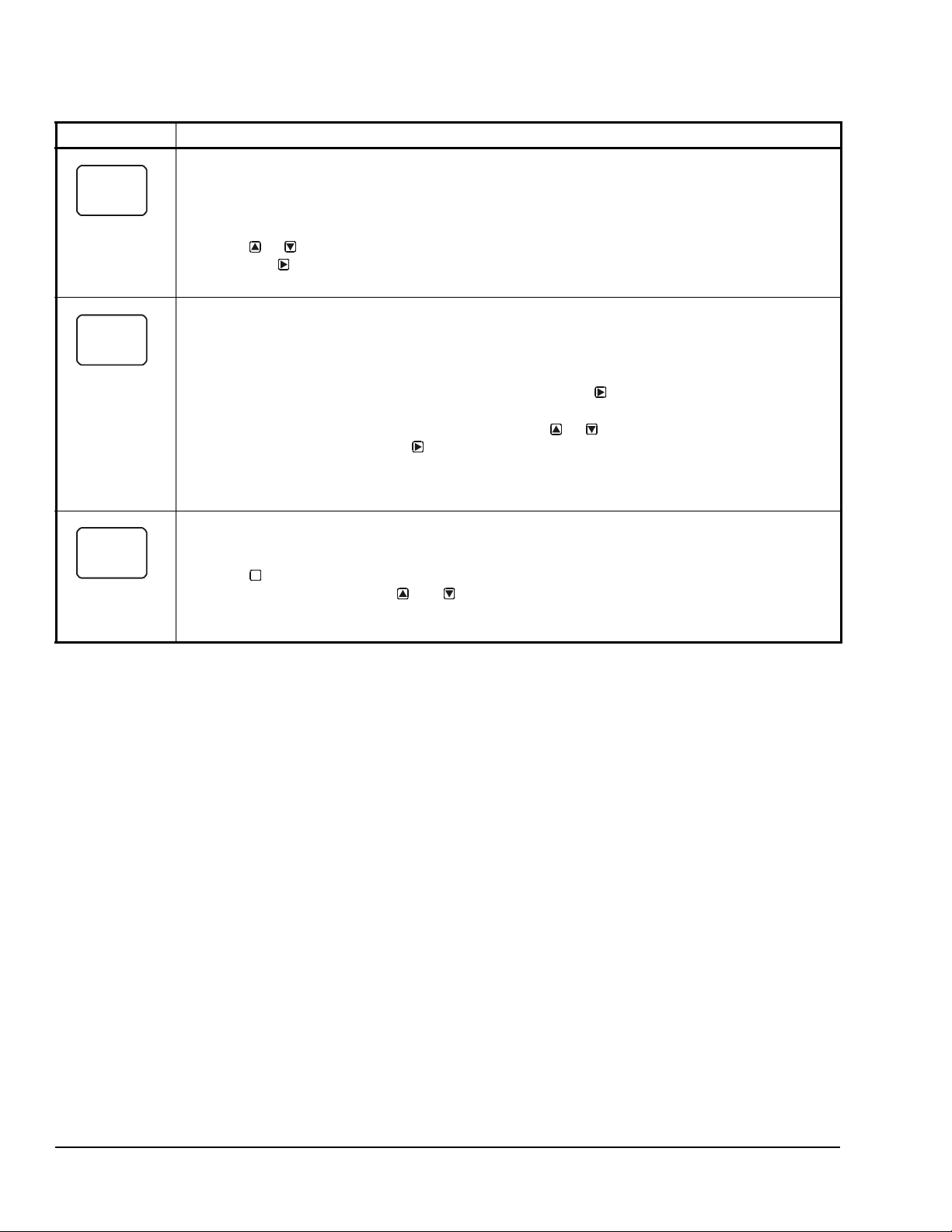
Table 11: System 450 Setup Screen Information and Procedures for Analog Outputs with Differential
SNF
2
OFF
SENS
2
Sn-d
OUTA
2
-- -
Control (Part 3 of 3)
LCD Screen Name, Description/Function, User Action, Example
Sensor Failure Mode Selection Screen: Select the differential output’s mode of operation if either of the
referenced sensors (Sn-1 or Sn-2) or the sensor wiring fails. The output operates in the selected mode
until the failure is fixed. Sensor Failure Mode selections for Analog Outputs include:
• ON = Output generates the selected OEP signal strength during sensor failure.
• OFF = Output generates the selected OSP signal strength during sensor failure.
8. Press or to select this output’s mode of operation if a referenced sensor or sensor wiring
fail. Press
The screen example shows OFF selected as the Sensor Failure mode for Output 2.
Edit Sensor Screen: This screen displays the Differential Sensor (Sn-d) that this output currently
references. Typically, no action is taken in this screen. But if you need to change the sensor that this
output references, you can select a different sensor for this output in this screen.
Note: If you change the Sn-d sensor to a different sensor, the output is no longer a Differential Control
output and you must set the output up again for the new sensor selection.
9. If you are not changing this output’s sensor, simply press to save the current sensor
selection and return to the Analog Output Setup Start screen.
To change the sensor this output references, press or to select the new sensor that this
output references. Then press to save the new sensor selection an d return to the Setpoint
Selection screen (SP or dSP). If the new sensor has a different Sensor Type from the previously
referenced sensor, repeat the output setup procedure for this output.
The screen example shows Sn-d as the selected Sensor for Output 2.
Analog Output Setup Start Screen
After you have set up this Analog Output, you can go to another Output Setup Start screen, the Sensor
Setup Start screen, or return to the Main screens.
10. Press to scroll through the remaining Output Setup Start screens and return to the Sensor
Setup Start screen, or press and simultaneously to return to the System 450 Main
screens.
The screen example shows the Analog Output Setup Start screen for Output 2.
to save your selection and go to the Edit Sensor Selection screen.
M
System 450™ Series Control Modules with Relay Outputs Installation Instructions20
Page 21
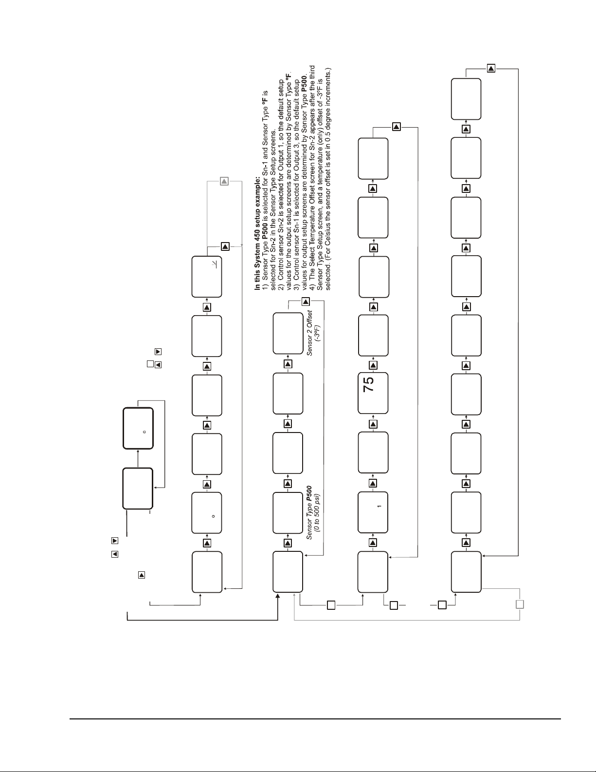
Figure 7: System 450 Status Screens, Setup Screens, and Menu Flow Example
Relay Output
Setup Start
OUTR
1
-- -
Sensor 2 Sel ected.
(Displayed only when a
Sensor is selected.)
not
Up to
ten
Outputs
can be
connected
and
set up.
M
Relay
Output
1
OUTA
3
OutputAnalog
Setup Start
Analog
Output
3
Select Relay ON
Value
ON
1
78
Relay
at ºF
1ON
78
OFF
1
Select Relay OFF
Value
Relay
at ºF
1OFF
75
Select Min
Relay ON
ONT
1
0
Relay
Seconds
(Minimum)
1ON
0
Select
Setpoint Value
Prop. Band
SP
3
200
Analog Output
Prop. Band
Setpoint psi
3
200
Sele
End
Ana
End
FIG:menu_flw_chrt
M
232
PSI
1
Main Screen
Sensor 2 Status
74
2
F
Sensor 1 Status
Up to ten Outp
can be set up
displayed.
Relay Output 2
Status
OFF
OUT
2
Output 2 Relay
OFF
Relay Output 1
Status
OUT
1
Output 1 Relay
On
Analog Output 3
Status
61
OUT
3
Output 3 Signal
at % of Range
61
Control Sensor 3
Status
----
3
Control Sensor 3
Not Set Up
Control Sen s or 2
Status
74ºF
74
2
F
232
PSI
1
Control Sensor 1
Status
232 psi
Sensor Set up
Screens
System Status
Screens
Main Screens
(Sensor Status)
Relay Output
Setup Screens
Analog Output
Setup Screens
M
Press and hold +
for 5 seconds to go to
the Setup Start screens.
Press to scroll through
Sensor Status screens and
Output Status screens.
Select
Control Sensor
Sn-2
SENS
SENS
Sensor Type
Setup Start
-- -
Select Sensor 2
Type
°F
Sensor Type
(-40 to 25 0ºF)
ºF
Select S ensor 3
Type
--
No
Sensor Type
Selected
Select Sensor 1
Type
P500
Sn-1
Sn-2 Sn-3
3
Select
Control Sensor
SENS
3
Sensor 1 Selected
(Displayed only
when a Sensor
is selected.)
not
Sn-1
Select
Temperature (on
Offset De gree
-3
OFFS
During normal op eration, the display au to m ati c
for all sensors set up in the UI .
After a 2 m inute pause in any set up or statu s s
Main (Sensor St at us ) scr ee ns.
Press in any Setup scree n t o go to the asso
Press + simultaneously in any Setup Star
M
On
2
M
-- -
Output 2
Setup Start
Screen
3
Edit
Control Sensor
1
1
Sn-2
1
SENS
2
Failure Mode
Sensor (Sn-2)
Controls Relay
1OFF
Select Se nsor
Edit
uts
and
Control S en sor
OFF
Relay
Failure Mode
ally scrolls through the Sensor Status screens
Main Screen
ciated Setup Start screen.
creen (below), the display returns to the
t screen to return to the Main screen.
ly)
s
Select S ensor
Select Minimum
Relay OFF T ime
Time
imum
SNF
1
120
if Sensor 2 Fails
1OFF
Seconds
(Minimum)
120
OFFT
Relay
Constant Value
Select Integration
at End Point
Signal Value
Select % Output
at Setpoint
Signal Value
Select % Output
Point Value
ct Prop. Band
1
Sn-1
SENS
Sensor (Sn-1)
3
3
OFF
SNF
Analog Output
3
0
3
I-C
Analog Output
90
3
90
OEP
Output Signal %
10
3
10
OSP
Output Signal %
3
3
250
EP
log Output Prop. Band
Controls
if
OFF
Integration
No
of Range at
of Range at
Analog Output
Sensor 1 Fails
Constant
Value
End Point
Value
Setpoint
250
Point psi
System 450™ Series Control Modules with Relay Outputs Installation Instructions 21
Page 22
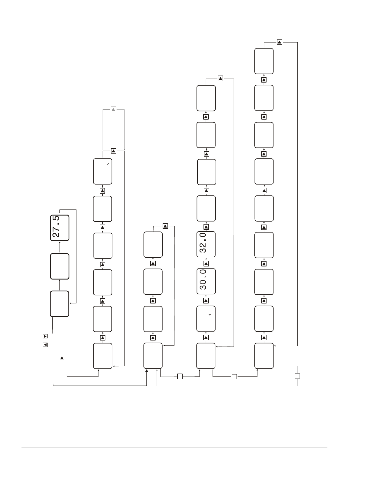
Figure 8: System 450 Status Screens, Setup Screens, and Menu Flow Example for Differential Control
Relay Output
Setup Start
OUTR
1
-- -
Up to
ten
Outputs
can be
connected
and
set up.
M
Relay
Output
1
OUTA
2
OutputAnalog
Setup Start
Analog
Output
2
Select Relay ON
Diffe r en ti al Value
dON
1
dOFF
1
Select Relay OFF
Diff er ential Value
Select Minim
Relay ON T
ONT
1
0
Select
Setpoint Value
Differential
dSP
2
30.0
Sele
End
2
FIG:Sys450_diffcontrol_menu_flow_chart
M
Main Screen
Sensor 2 Status
Sensor 1 Status
Relay Output 1
Status
OUT
1
Analog Output 3
Status
50
OUT
2
Sensor 3 St at us
----
3
Sensor 2 Status Sensor 1 Status
Sensor Setup
Screens
System Status
Screens
Main Screens
(Sensor Status)
Relay Output
Setup Screens
for Differential
Control
Analog Output
Setup Screens
for Differential
Control
M
Press and hold +
for 5 seconds to go to
the Setu p St ar t screens.
Press to scroll throug h
Sensor Status screens and
Output St atus screens.
Select
Control Sensor
Sn-d
SENS
SENS
Sensor Type
Setup Start
-- -
Selec t Sensor 2
Type
P100
Select Sensor 3
Type
Select Sensor 1
Type
--
Sn-1
Sn-2 Sn-3
2
Select
Control Sensor
SENS
2
Sn-d
On
-- -
P100
62.5
1
PSI
35.0
PSI
2
62.5
PSI
1
35.0
PSI
2
Selections for Setting Up Relay Output 1 to Enable/Disable Variable Speed Drive for Booster Pump by Pressure Differen
(Drive On when Sn-d repor ts a 28 psi or less di f ferential and dri ve Off when Sn-d repo r ts a 30 psi or grea t e r di ff erentia l .)
(No Sensor)
Selections for Setting Up Analog Output 2 to Control Variable Speed Drive for Booster Pump by Pressure Dif
(Drive delivers 5% output at 25 psi or greater differential and ramps up 100% outp
as pressure d ifferential decreases, deliveri ng
Because the sam e Sesnor T ype (P100) is selected for Sn-1 and
the Differential Contro l sensor (Sn-d) is ava ilable fo r s election wh
outputs for this con trol system are set up.
The High Input-Signal Selection sensor for two sensor app
(HI-2) is also available for selection when Sn-1 and Sn-2 are the
Sensor Type.
Note:
DIfP
Differential Control
Sensor Status
DIfP
Differential Control
Sensor Stat us
Main Screens show status of Sn-1, Sn-2, and Sn-d.
(Sn-d is Status screen is labeled DIfP (Di ff erential
Pressure) beca use Sn-1 and Sn-2 are th e same
pressure Sens or Type (P100).
Up to ten Ou
can be set up
displayed
27.5
Note:
For mor e i nformat ion on setting up Rel ay O utput 1 an d Anal og Output 2 see Table 10 and Table
Edit
Sn-d
Control Sensor
en the
Sn-2,
and
.
tputs
lications
same
Edit
Control Sensor
1
Sn-d
SENS
1
tial
Failure Mode
Select Sensor
SENS
2
OFF
SNF
0
2
ferential
ut at 20 ps i or less.)
11.
OFF
Failure Mode
Select Sensor
SNF
Consta nt Value
Select Integration
I-C
1
30
Select Minimum
Relay OFF Time
um
ime
OFFT
Signal Value
Select % Output
2
100
at End Point
OEP
2
0
at Setpoint
Signal Value
Select % Output
Point Value
ct Differential
Main Screen
OSP
2
5.0
dEP
System 450™ Series Control Modules with Relay Outputs Installation Instructions22
Page 23

Technical Specifications
C450CxN-2
Product C450CxN-2: System 450 Control Modules are sensing controls and operating controls
with LCD, four-button touch pad, and On/Off relay output.
C450CBN-2: Control Module with one SPDT output relay
C450CCN-2: Control Module with two SPDT output relays
Supply Power C450YNN-1 Power Supply Module or 24 (20-30) VAC Safety Extra-Low Voltage (SELV)
(Europe) Class 2 (North America), 50/60 Hz, 10 VA minimum
Ambient Operating Conditions Temperature: -40 to 66°C (-40 to 150°F)
Humidity: Up to 95% RH noncondensing; Maximum Dew Point 29°C (85°F)
Ambient Shipping and Storage
Conditions
Input Signal 0 to 5 VDC; 1,035 ohms at 25°C (77°F) for an A99 PTC Temperature Sensor;
Output Relay Contacts General: 1/2 HP at 120/240 VAC, SPDT
Analog Input Resolution: 14 bit
Control Construction Independently mounted control, surface mounted with Lexan® 950 enclosure suitable
Dimensions (H x W x D) 127 x 61 x 61 mm (5 x 2-3/8 x 2-3/8 in.)
Weight C450CBN-2: 209 gm (0.46 lb)
Compliance North America: cULus Listed; UL 60730, File E27734, Vol. 1; FCC Compliant to
The performance specifications are nominal and conform to acceptable industry standards. For application at conditions beyond these
specifications, consult Johnson Controls Application Engineering at (414) 524-5535. Johnson Controls, Inc. shall not be liable for damages
resulting from misapplication or misuse of its products.
United States Emissions Compliance
This equipment has been tested and found to comply with the limits for a Class B digital device, pursuant to Part 15 of the FCC Rules. These
limits are designed to provide reasonable protection against harmful interference in a residential installation. This equipment generates, uses
and can radiate radio frequency energy and, if not installed and used in accordance with the instructions, may cause harmful interference to
radio communications. However, there is no guarantee that interference will not occur in a particular installation. If this equipment does cause
harmful interference to radio or television reception, which can be determined by turning the equipment off and on, the user is encouraged to try
to correct the interference by one or more of the following measures:
- Reorient or relocate the receiving antenna.
- Increase the separation between the equipment and receiver.
- Connect the equipment into an outlet on a circuit different from that to which the receiver is connected.
- Consult the dealer or an experienced radio/TV technician for help.
Canadian Emissions Compliance
This Class (B) digital apparatus meets all the requirements of the Canadian Interference-Causing Equipment Regulations.
Cet appareil numérique de la Classe (B) respecte toutes les exigences du Règlement sur le matériel brouilleur du Canada.
T emperature: -40 to 80°C (-40 to 176°F)
Humidity: Up to 95% RH noncondensing; Maximum Dew Point 29°C (85°F)
1,000 ohms at 21.1°C (70°F) for a Nickel Temperature Sensor
Specific: AC Motor Ratings 120 VAC 208/240 VAC
AC Full-Load Amperes: 9.8 A 4.9 A
AC Locked-Rotor Amperes: 58.8 A 29.4 A
_____________________________________
10 Amperes AC Non-Inductive at 24/240 VAC
Pilot Duty: 125 VA at 24/240 VAC
for DIN rail mounting or direct mounting to a hard, even surface.
C450CCN-2: 222 gm (0.49 lb)
CFR47, Part 15, Subpart B, Class B
Industry Canada (IC) Compliant to Canadian ICES-003, Class B limits
Europe: Mark: CE Compliant; Low Voltage Directive (2006/95/EC); EMC Directive
(2004/108/EC); RoHS Directive (2002/95/EC); WEEE Directive (2002/9 6/EC)
Australia: Mark: C-T ick Compliant (N1813)
System 450™ Series Control Modules with Relay Outputs Installation Instructions 23
Page 24

System 450™ Series Control Modules with Relay Outputs Installation Instructions24
Metasys® and Johnson Controls® are registered trademarks of Johnson Controls, Inc.
All other marks herein are the marks of their respective owners. © 2012 Johnson Controls, Inc.
Building Efficiency
507 E. Michigan Street, Milwaukee, WI 53202
Published in U.S.A. www.johnsoncontrols.com
 Loading...