

Page 1

BACnet Controller Integration Technical
Bulletin
Building Technologies & Solutions
www.johnsoncontrols.com
2021-02-05
LIT-1201531
Release 11.0
Page 2

2 BACnet Controller Integration Technical Bulletin
Page 3

Contents
Contents
Introduction.................................................................................................................................................... 5
Summary of changes.......................................................................................................................... 5
BACnet Controller Integration overview..................................................................................................... 5
BACnet Integration.............................................................................................................................. 5
BACnet Integration/Field Bus Integration object............................................................................ 7
Focus view................................................................................................................................................... 7
Diagnostics view......................................................................................................................................... 7
Engineering view........................................................................................................................................ 7
Summary view............................................................................................................................................ 8
Hardware view (Field Bus integration only)........................................................................................... 8
BACnet Integration and Field Bus Integration Auto Discovery filtering....................................... 8
BACnet Integration Auto Discovery filters.............................................................................................. 8
Field Bus Integration Auto Discovery filters........................................................................................... 9
BACnet object support...................................................................................................................... 10
Unique device object identifiers............................................................................................................. 11
Items in the Navigation tree on the SMP UI.................................................................................. 11
Commands................................................................................................................................................ 12
Alarming.................................................................................................................................................... 16
Performance considerations for third-party BACnet devices...................................................... 16
Exposing network engine data to M-Series Workstations........................................................... 17
Supported network engine objects................................................................................................. 18
Exposing data as standard BACnet objects to other BACnet devices......................................... 19
Adjusting the poll rate for third-party BACnet devices................................................................. 19
Configuring a Network Engine as a BACnet/IP to MS/TP Router................................................ 19
Auto-Created States Text.................................................................................................................. 19
Detailed procedures.................................................................................................................................... 23
Connecting to BACnet devices......................................................................................................... 23
Exposing BACnet information.......................................................................................................... 23
Adding a BACnet Integration object............................................................................................... 24
Mapping BACnet/IP Devices using Auto Discovery....................................................................... 26
Mapping BACnet/IP devices manually............................................................................................ 27
Mapping BACnet Field Points using Auto Discovery..................................................................... 28
Mapping BACnet Field Points manually.......................................................................................... 31
Using the Relearn feature................................................................................................................ 33
Using the Engineering view to View and Edit Device Attributes (BACnet
Properties)................................................................................................................................ 33
Field Bus Integration object — detailed procedures............................................................................... 34
Adding BACnet MS/TP (Field Bus) Integrations............................................................................. 34
Manually adding BACnet MS/TP (Field Bus) Field Devices (online or offline)............................ 35
Adding BACnet MS/TP Field Devices online using Auto Discovery............................................. 37
Adding BACnet Devices to the BACnet and MSTP Integrations using the Import
Integration Wizard................................................................................................................... 37
BACnet Controller Integration Technical Bulletin 3
Page 4

Adding extensions to an object....................................................................................................... 38
Adding a Trend Extension....................................................................................................................... 38
Adding a Totalization Extension............................................................................................................. 39
Adding an Alarm Extension.................................................................................................................... 40
Adding a Load Extension........................................................................................................................ 41
Adding an Averaging Extension............................................................................................................. 42
Deleting extensions from an object................................................................................................ 42
Copying extensions to a Field Device or Field Point (offline only).............................................. 42
Enabling the routing mode.............................................................................................................. 43
BACnet routing considerations.................................................................................................................. 43
Related documentation............................................................................................................................... 44
Troubleshooting........................................................................................................................................... 45
BACnet System Integration troubleshooting guide...................................................................... 45
Product warranty......................................................................................................................................... 49
Software terms............................................................................................................................................. 49
Patents........................................................................................................................................................... 49
Single point of contact................................................................................................................................. 49
Contact information..................................................................................................................................... 49
BACnet Controller Integration Technical Bulletin4
Page 5

Introduction
This document describes how BACnet® controllers, both those from Johnson Controls and thirdparty suppliers, are integrated into the Metasys system through the NAE, NCE, SNE, and SNC series
network engines, OAS series Open Application Server, or ODS series Open Data Server all hereafter
referred to as supervisory devices. This capability provides two major functions:
• First, this BACnet integration allows the objects within BACnet controllers to be interfaced with
the Site Management Portal.
• Second, this BACnet integration enables the supported supervisory controllers to provide
supervisory control and monitoring functions for objects integrated from connected BACnet
controllers. BACnet controllers can integrate with a supervisory controller using either BACnet/
IP or MS/TP communications.
Note: In this document, all NCE25, NAE35, and NAE45 content relates to Release 9.0.8. NAE55/
NAE85/LCS85 are supported at Release 11.0. All SNE and SNC content relates to 11.0.
The functions provided by the supervisory controllers for BACnet controllers are similar to those
provided to integrated N2 and LonTalk® controllers. The major difference is that the supervisory
controller behaves as a BACnet gateway to the non-BACnet controllers, converting their data into
BACnet objects that reside within the supervisory controller. For integrated BACnet controllers,
the supervisory controller provides BACnet mapper objects, which supplement the standard
BACnet object data of the integrated controllers with additional attributes needed to perform the
workstation and building controller functions within the Metasys system. This document describes
those additional attributes.
Note: The term supervisory controller is used throughout this document to refer to the
variants of controllers that support BACnet controller integration, including NAE, NCE, SNE,
and SNC series network engines, the OAS series Open Application Server, and the ODS series
Open Data Server.
Summary of changes
Updated Metasys Release references to 11.0 throughout the document.
BACnet Controller Integration overview
As a BACnet integrator, the supervisory controller monitors and supervises a network of BACnet
devices and acts as a BACnet operator workstation for all integrated controllers. Data is presented
to the operator through the Site Management Portal UI of the supervisory controller. Other BACnet
devices on the network can read from and write to the BACnet objects within the supervisory
controller.
BACnet Integration
The BACnet Integration allows the integration of BACnet devices into the Metasys system. Figure 1
shows an example of this type of configuration. As shown, third-party BACnet devices can reside on
the IP Network and on the MS/TP Field Bus.
5BACnet Controller Integration Technical Bulletin
Page 6
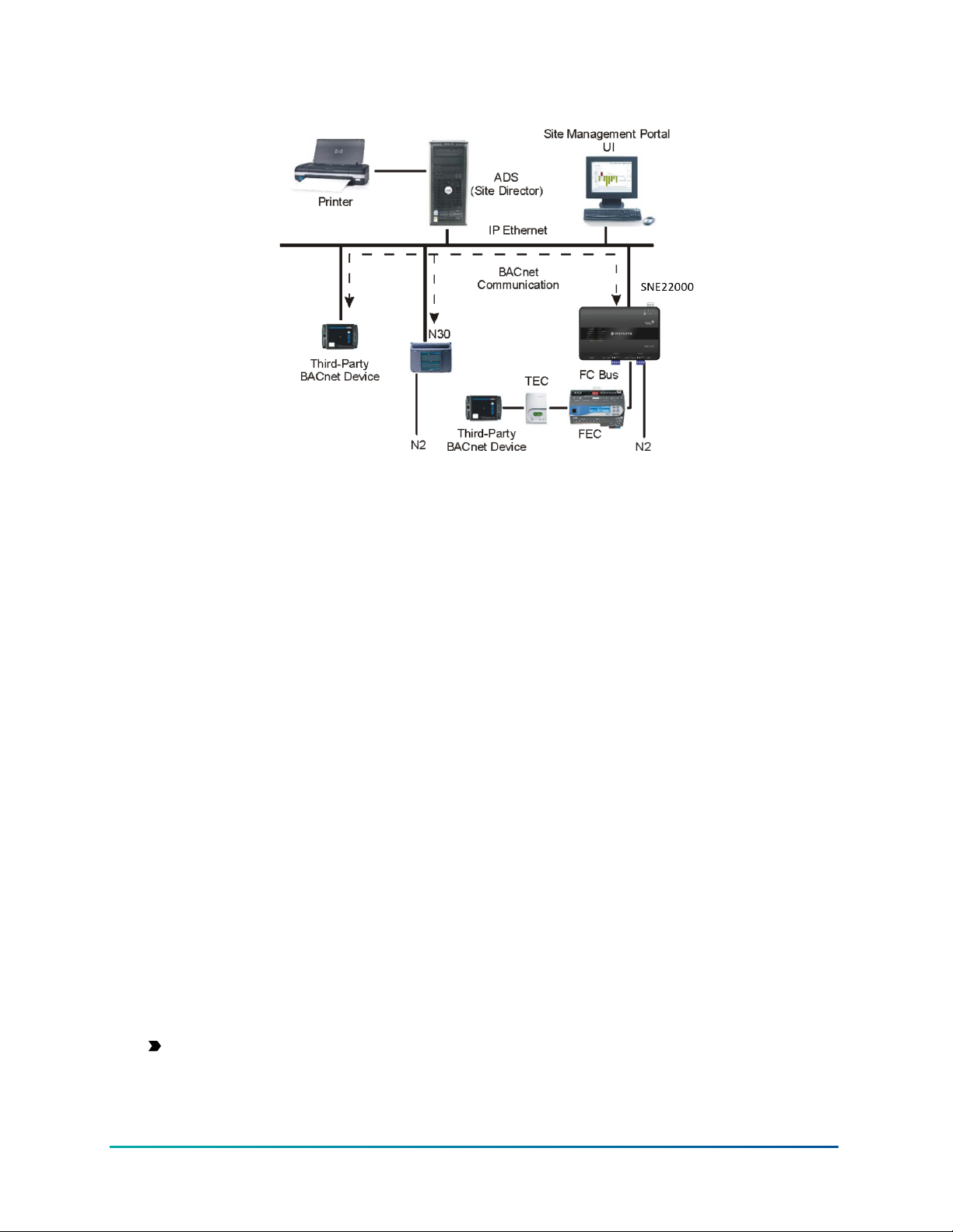
Figure 1: BACnet system integration configuration example
Two software objects in the supervisory controllers enable integration to BACnet controllers:
• The BACnet IP Integration supports the connection of BACnet/IP devices.
• The Field Bus MSTP Integration supports the connection of BACnet MS/TP devices via a
local Field Bus or a Remote Field Bus connection. Field Bus integrations on trunk 1 and 2 are
exposed as BACnet Network Port objects.
The supervisory controller, with the Site Management Portal as its UI, serves as a BACnet
workstation on which to view and command standard BACnet objects in BACnet devices. It maps
the BACnet system data to create integrated objects to use in Metasys system applications, and to
use in features such as interlocking and demand limit/load rolling.
By using the BACnet Integration and Field Bus Integration in a supervisory controller, you can map
the desired BACnet devices and objects.
Notes:
• BACnet devices that auto-discover the objects in a supervisory controller, such as a third-party
BACnet workstation, identifies the mapper objects, not the actual BACnet objects in the field
devices. The mapper objects have all the same standard attribute values of the original objects
of the integrated devices, except for the BACoid, for which the mapper object has a unique
number that is different from that of the original object. The Device Objects themselves of
the integrated devices do not have mapper objects. Thus, the BACnet device recognizes the
supervisory controller as a single device with a large collection of all the integrated standard
objects that are mapped from the integrated devices. FX products are treated as third-party
devices on the BACnet integrations.
• The BACnet devices can discover MS/TP field devices and objects by enabling the BACnet/IP
to MS/TP routing feature in the NAE. See the Configuring a Network Engine as a BACnet/IP to
MS/TP Router section.
Important: BACnet routing can greatly increase the amount of message traffic on
the MS/TP bus. This can, in turn, cause a major reduction in performance. Refer to the
Adjusting NAE network sensitivity section in the NAE Commissioning Guide (LIT-1201519) for
ways to improve performance by adjusting network parameters.
BACnet Controller Integration Technical Bulletin6
Page 7

BACnet Integration/Field Bus Integration object
In most instances, the supervisory controller has a BACnet integration. Use the BACnet Integration
to configure the parameters for BACnet integration in the supervisory controller that is monitoring
BACnet/IP devices. For more information about the BACnet Integration object, including attributes
and commands, refer to the Object Help in the Metasys SMP Help (LIT-1201793).
Note: NxE/SNx's can only have one BACnet/IP Integration.
Use the Field Bus MSTP Integration to connect BACnet MS/TP devices to a supervisory controller.
The specific model of supervisory controller must either have an available RS-485 communication
connection or use the remote field bus integration if the MS/TP devices are accessible through a
BACnet/IP to MS/TP router. In this case, the router provides the RS-485 communication instead of
the supervisory controller.
Note: Make sure you map field devices under a remote field bus to only one supervisory
controller. If you map the same remote controllers to multiple supervisors, these devices
may cycle online and offline and you may experience slow startup performance. For more
background on the remote field bus, refer to the MS/TP Communications Bus Technical Bulletin
(LIT-12011034).
The BACnet Integration object offers four views, while the Field Bus Integration object adds a fifth
view:
• Focus view
• Diagnostics view
• Engineering view
• Summary view
• Hardware view (Field Bus integration only)
Note: Only the focus view is available during offline configuration with the SCT.
Focus view
The focus view contains basic user data including the name of the object and the device name of
the host supervisory controller for the BACnet integration object.
Diagnostics view
The diagnostics view displays BACnet protocol diagnostic properties for troubleshooting purposes.
Note: This view is not available during offline configuration with the SCT.
Engineering view
The engineering view of the BACnet Integration allows scanning the entire IP network to discover
and view data in BACnet devices that are connected on the network, whereas the Field Bus object’s
engineering view shows the devices connected to the corresponding MS/TP bus. Advanced users
(with the appropriate access authority) use this view to see and change data in BACnet devices
directly, whether or not the objects have been integrated to the supervisory controller. A user can
then view and command many more BACnet devices than just those that have been integrated and
are visible in the Site Management Portal All Items navigation tree.
The engineering view contains the Integration Tree and Integration View panels. The Integration
Tree panel contains a list of known BACnet devices and their objects that are connected to the
supervisory controller. The Integration View panel displays the details about the BACnet device or
objects selected in the Integration Tree.
7BACnet Controller Integration Technical Bulletin
Page 8

After you create a new BACnet Integration or Field Bus Integration, the Integration Tree is empty
until you add the BACnet devices by using auto discovery.
Note: This view is not available for offline configuration with the SCT.
Summary view
The Summary view shows a list of all mapped devices and the current values of key data about each
device.
Note: This view is not available for offline configuration with the SCT.
Hardware view (Field Bus integration only)
The hardware view shows the Field bus trunk number, baud rate and network address.
BACnet Integration and Field Bus Integration Auto Discovery filtering
When you map BACnet/IP devices or Field Bus integration devices using auto discovery, the list of
devices may become so long that it is difficult to find a device in the list. You can use a number of
attributes in the Advanced Focus view to filter your view and make the list more manageable. You
can configure this filtering using a collection of attributes located on the Advanced Focus view of
the BACnet integration object or Field Bus Integration object.
When devices are discovered, the discovery list displays the devices previously mapped by default.
Additional devices are then added as they are discovered.
BACnet Integration Auto Discovery filters
• Device Discovery Range—This attribute is a list of filters arranged so that a device that
matches any of the list entries displays in the Auto Discovery list. The default attribute value
is no entries, which allows all reachable devices to be discovered. Each list entry has the
following parts:
- Broadcast Type - This entry filters the scope of the device discovery process at a BACnet
network level. This entry has three options:
- Local - Discovers devices only on the local BACnet/IP network (network number
zero [0] is defined by BACnet as the local network).
- Remote - Discovers devices only on a particular BACnet network that must be
specified.
- Global - Discovers devices on all BACnet networks that are reachable (network
number 65535 is defined by BACnet as the global broadcast network number).
- Network Number - The network number can only be entered when the Broadcast Type is
set to Remote.
- Device Instance Low Limit - Each BACnet device is required to have a unique instance
number at a site. The Device Instance Low Limit value specifies the lowest device instance
number discovered on a network. The range for this value is 0 to 4194303. A device with
an instance number zero is not discovered when using this filter.
- Device Instance High Limit - The Device Instance High Limit value specifies the highest
device instance number discovered on a network. The range for this value is 1 to 4194303
and must be at least one number greater than the Device Instance Low Limit. A device
cannot have an instance number higher than the range limit.
BACnet Controller Integration Technical Bulletin8
Page 9

• Preserve Discovered Devices—This attribute determines whether devices discovered
during a previous Auto Discovery operation are preserved during subsequent Auto Discovery
operations. If the attribute is set to True, devices previously discovered are preserved. If the
attribute is set to False, then devices previously discovered are not preserved. By default, this
attribute is set to True.
Set the attribute to True to collect an inclusive list of devices by performing discovery multiple
times with different filter settings.
Set the attribute to False to narrow the discovery list to the current filter settings.
• Discover All As General BACnet Device— If the attribute is set to True, the BACnet/IP
integration allows for the discovery of JCI supervisory controllers. On both IP and MS/TP
integrations the devices are discovered as general BACnet devices rather than JCI Family
BACnet devices and this prevents you from using JCI enhanced BACnet features. However,
setting the attribute to False does not prevent the discovery of JCI IP field devices as JCI IP field
devices are always discovered on the BACnet/IP integration.
Note: If you change the attribute after running Auto Discovery, we recommend you restart
the supervisory controller when configuration is complete.
• Requested Vendor ID—The BACnet Vendor ID is a numerical value assigned to the vendor of
the device. By default, this attribute is empty (or at zero), allowing all vendors to be discovered.
If a number other than zero is entered, only devices with a matching vendor ID display in the
discovery list. BACnet maintains a list of vendor IDs at http://www.bacnet.org.
• Page Size—This attribute filter applies only to point object discovery within a single device,
and limits the number of displayed objects to a quantity within the display capability of the Site
Management Portal (SMP) UI. When the page size reaches the limit, click Restart on the object
discovery list to move to the next page. If you click Restart on the last page of the discovery
list, the object discovery runs again and produces a new page 1. The range of point objects
displayed per page is 10 to 1,000.
Field Bus Integration Auto Discovery filters
Field Bus integrations are associated with a particular BACnet network number. During Auto
Discovery, only devices connected directly to that particular BACnet network are discovered. A
device is classified as either a General BACnet Device or as a JCI Family BACnet Device. General
BACnet Devices are managed using standard BACnet services and properties. JCI Family BACnet
Devices are managed using enhanced BACnet services and include proprietary properties in order
to improve performance and to display additional details about the device and its objects. Devices
that are not JCI Family devices are always managed as General BACnet Devices.
• Discover All As General BACnet Device—This attribute determines whether a Johnson
Controls Device in the FEC/FAC/VMA or CGM/CVM series family is classified as a JCI BACnet
Device or as a General BACnet Device. By default, this attribute is set to False, and classifies
the device as JCI BACnet Devices so that performance is optimized and proprietary properties
display. When this attribute changes, any previous discovery information clears and Auto
Discovery must run again.
Note: If you change the attribute after running Auto Discovery, we recommend you
restart the NxE when configuration is complete.
• Requested Vendor ID—The BACnet Vendor ID is a numerical value assigned to the vendor of
the device. By default, this attribute is empty (or at zero), allowing all vendors to be discovered.
If a number other than zero is entered, only General BACnet Devices with matching vendor
IDs display in the discovery list. JCI BACnet devices always display on the discovery list. BACnet
maintains a list of vendor IDs at http://www.bacnet.org.
9BACnet Controller Integration Technical Bulletin
Page 10

BACnet object support
The Metasys system integrates and exposes objects as standard BACnet object types. The user
configures and enables the BACnet Integration and Field Bus Integration feature in the supervisory
controllers.
The Metasys system supports a subset of standard BACnet object types, but does not support
integration of any proprietary object types in other BACnet devices. Of the supported standard
BACnet objects, only the required and optional properties are viewable for non Metasys Series
controllers (referred to as General BACnet Device in this document); proprietary properties are not
supported.
The following list of BACnet object types are both those supported in the Metasys supervisory
controllers for BACnet/Field Bus integration, and those exposed as BACnet objects to third-party
BACnet devices that discover the supervisory controller. Refer to the Object Dictionary in online Help
or the Network Engine Protocol Implementation Conformance Statement Technical Bulletin (LIT-1201532)
for further details on objects supported.
Important: Electric Demand Control, Electric Demand Monitoring, and Generator Load Control
objects are intended for use only in Japan.
• Accumulator
• Analog Input (AI)
• Analog Output (AO)
• Analog Value (AV)
• Averaging
Note: Averaging objects created in the NAE appear as extensions to the object that the
average is associated with. When exposed to a third-party BACnet device, the extension
appears as its own BACnet Averaging object.
• Binary Input (BI)
• Binary Output (BO)
• Binary Value (BV)
• Bitstring Value (ODS only)
• Calendar
• Characterstring Value
• Command
• Date Pattern Value (ODS only)
• Date Time Pattern Value (ODS only)
• Date Time Value (ODS only)
• Date Value (ODS only)
• Device (only the NAE/NCE/SNE/SNC exposes the Device object)
• Event Enrollment
• Electric Demand Control
• Electric Demand Monitoring
• File
• Generator Load Control
• Group
BACnet Controller Integration Technical Bulletin10
Page 11

• Integer Value
• Large Analog Value (ODS only)
• Life Safety Point
• Life Safety Zone
• Load Control
• Loop
• Multistate Input (MI)
• Multistate Output (MO)
• Multistate Value (MV)
• Notification Class (Notification)
• Octet String Value (ODS only)
• Positive Integer Value
• Program (the Metasys Control System object qualifies as a BACnet Program object)
• Pulse Converter
• Schedule
• Time Pattern Value (ODS only)
• Time Value (ODS only)
• Trend
Note: Trend objects created in the supervisory controllers appear as extensions to the object
that the trend is associated with. When exposed to a third-party BACnet device, the extension
appears as its own BACnet Trend object.
• Trend Log Multiple
In the network engine, all mapped field points, including those on the N2 Bus, LonWorks® trunk as
well as all field bus and BACnet integrated points are exposed as the corresponding BACnet objects
types (AI, AO, BI, BO, MSI and so on) to third party BACnet devices. By default, the network engines
do not allow routing messages to MS/TP devices connected to a network engine field bus. If you
do enable routing, third party devices can map devices and their points connected to the local field
buses.
Important: Do not enable routing during normal operation on NCE25, NAE35 or NAE45 series
network engines as the increased traffic will likely increase offline/online event reporting.
See Enabling the routing mode.
Unique device object identifiers
Each BACnet device object at a site must have a unique instance number and name. The BACnet
device object instance number and name are assigned in the field as part of the installation
configuration. When assigning instance numbers and names to device objects at a site, we
recommend maintaining a list of devices and their assigned BACnet device object unique instance
numbers and names.
Items in the Navigation tree on the SMP UI
When an object appears in the Navigation tree that represents an object located in other devices, it
is called an integrated (mapped) BACnet object. The integrated BACnet object has a new BACnet ID
that is different from the ID of the physical BACnet object being mapped.
11BACnet Controller Integration Technical Bulletin
Page 12

BACnet objects that appear in the Navigation tree on the Site Management Portal UI can be used
as object references to other objects on the Metasys site (for example, scheduling, trend study, and
DL/LR), allowing the integrated object to be referenced as any other Metasys system object.
Discovered BACnet/IP and MS/TP devices are not automatically added to the Navigation tree. The
following rules apply when adding BACnet device objects and BACnet objects to the Navigation
tree.
Add the:
• BACnet/IP device under the BACnet Integration object, or BACnet MS/TP device under the Field
Bus Integration object
• Folder (container) objects under the BACnet device to group BACnet objects within a BACnet
device
Note: Adding folder objects is optional. For the easiest reference, put more important
information points in the root directory and other information points into folders.
• BACnet objects directly under a BACnet device, or in folders under a BACnet device
When you select an integrated BACnet object from the navigation tree, the Focus view displays the
BACnet properties in an available panel of the UI.
While most of the properties are directly inherited from the actual BACnet object in the integrated
device, the mapped object in the NAE may have additional or different properties.
Commands
Only those Metasys system commands that can be implemented by a standard BACnet service
are supported on an integrated BACnet object. Some BACnet objects support commands that are
handled by writing to the remote BACnet object’s properties.
The following table lists the commands that are available for each of the BACnet object types that
are supported in the supervisory controller for BACnet/Field Bus integration.
Table 1: Command name table
Adjust
Temp Override
Temp Out of Service
In and Out of Service
Command Name
Accumulator X X X
Analog Input
(AI)
Analog
Output (AO)
Analog
Value(AV)
Averaging
Override/ Override Release
X X X
X X X X X X X
X X X X X X
Reset Field Device
Sync Field Device Times
Release
State N, or Set State
Route
Release All
Enable and Disable Alarms
Preset Value
Add/Remove Recipient
Clear and Execute
Rediscover Text Strings
Restore Controller States Text
Program Changes
Shed
BACnet Controller Integration Technical Bulletin12
Page 13

Table 1: Command name table
Command Name
BACnet
Character
String Value
BACnet
Electric
Demand
Control (EDC)
BACnet
Electric
Demand
Monitoring
(EDM)
BACnet
Generator
Load Control
(GLC)
BACnet
Integer Value
BACnet
Positive
Integer Value
Binary Input
(BI)
Binary
Output (BO)
Binary Value
(BV)
BitString
11
Value
Adjust
Temp Override
Temp Out of Service
In and Out of Service
Reset Field Device
Sync Field Device Times
Override/ Override Release
Release
State N, or Set State
Route
Release All
Enable and Disable Alarms
Preset Value
Add/Remove Recipient
Clear and Execute
Rediscover Text Strings
X X X X X X
X X
X X
X X
X X X X X X
X X X X X X
X X X X
X X X X X X X X
X X X X X X X
X X X X X X
Restore Controller States Text
Program Changes
Shed
Calendar
Command X X
Date Pattern
Value
1
X X X X X
13BACnet Controller Integration Technical Bulletin
Page 14

Table 1: Command name table
Route
Release All
Enable and Disable Alarms
Preset Value
Add/Remove Recipient
Clear and Execute
Temp Override
Command Name
Override/ Override Release
Temp Out of Service
In and Out of Service
Reset Field Device
Sync Field Device Times
Adjust
Release
State N, or Set State
Date Time
Pattern
1
Value
X X X X X
Date Time
1
Value
Date Value
X X X X X
1
X X X X X
Device X X X
Electric
Demand
X X X
Control
Electric
Demand
X X X
Monitoring
Event
Enrollment
(EEO)
Generator
Load Control
X X X
Rediscover Text Strings
Restore Controller States Text
Program Changes
Shed
Group
Large Analog
Value
Life Safety
Point (LSP)
Life Safety
Zone (LSZ)
X X X X X X
X X
X X
Load Control X X X
Loop X X X
Multistate
Input (MI)
Multistate
Output (MO)
X X X X X X X X
X X X X
BACnet Controller Integration Technical Bulletin14
Page 15

Table 1: Command name table
Route
Release All
Enable and Disable Alarms
Preset Value
Add/Remove Recipient
Clear and Execute
Rediscover Text Strings
Restore Controller States Text
X
Command Name
Multistate
Value (MV)
Notification
Class (NCO)
Adjust
Release
Temp Override
Temp Out of Service
In and Out of Service
Reset Field Device
State N, or Set State
Sync Field Device Times
Override/ Override Release
X X X X X X X
Octet String
Value
1
X X X X X
Program X
Pulse
Converter
X X
Schedule X
Time Pattern
1
Value
Time Value
X X X X X
1
X X X X X
Trend X X X
Program Changes
Shed
Trend Log
Multiple
1 Applicable to ODS only
X X
Operation for most of these commands can be found in Metasys SMP Help (LIT-1201793). The
following command operations are unique to the BACnet integration:
• Restore Controller States Text: For objects supporting the States Text attribute, if the User
Selected States Text attribute is true, the object's States Text is no longer synchronized with
the States Text, Action Text, Active/Inactive, or Shed Level Description property. Use the
Restore Controller States Text to set User Selected States Text to false. The field point's States
Text attribute is then updated to match the remote object's States Text property.
Note: If the dictionary cannot be updated to match the field device, the States Text Error
Status attribute indicates the cause of the error.
• State N: The State N Command is used by the Command object to write the Present Value
attribute by selecting a state. The first state in the drop-down box indicates No Action, and the
remainder of the states indicate an Action from the Action array. If you choose to define your
own custom enumeration set for this object, be sure to enter No Action for the first entry.
15BACnet Controller Integration Technical Bulletin
Page 16

• Add Recipient and Remove Recipient for the Notification Object: Use this command to add
or remove the parent supervisory device as a notification recipient for the selected Notification
object.
• Adjust: For the Loop object, the Adjust command writes the Setpoint attribute.
• Out of Service and Temporary Out of Service: If you want to write and make reliable Present
Value, first select an out of service or temporary out of service command to the input object,
then set the Value before issuing the command. Objects that include this functionality include
Accumulator, AI, BI, MSI, Pulse Converter, and Schedule mappers.
Alarming
The supervisory controller accepts alarms from BACnet devices if those devices have a Notification
Class object with the supervisory controller specified as a recipient for the alarms, and if the
sources of the alarms are mapped as integrated BACnet objects.
The remote BACnet device notification class object has a destination Process ID for each recipient
entry. By default, the supervisory controller accepts alarms for all valid Process ID values. For each
supervisory controller, you can filter alarms and accept only those matching specific Process IDs.
The supervisory controller's device object contains an attribute under the BACnet section of the
Focus tab called Process Id List. Adding Process ID values to this attribute tells the supervisory
controller to only accept alarms matching those Process IDs values. There are two special cases that
tell the supervisory controller to accept alarms for any Process ID: if the list is empty (which is the
default) or if the list contains a Process ID of 0.
You can also configure the supervisory controller's Notification Class objects to send alarms to
remote BACnet devices. The Metasys system audit trail then records the Alarm acknowledgments
from the BACnet device.
Performance considerations for third-party BACnet devices
Network performance can degrade when you add third-party devices on the same IP network or
MS/TP trunk if those devices do not meet the Required recommendations in Table 2. Actual job
experience has shown as few as five devices can create significant performance issues; although
other variables can affect performance, such as the number of objects per device. To improve
network performance, we recommend that third-party devices also meet the Highly Desired
recommendations in Table 2.
Table 2: Third-Party BACnet Device Performance Recommendations
MS/TP Trunk, IP Network, and BACnet Services Recommendation
Devices On MS/TP Trunk
MS/TP Master Device Required
At least 38,400 bps Highly Desired
Application Layer Protocol Data
Unit (APDU) size 480 bytes
APDU size >200 Highly Desired
Segmentation on MS/TP Desired
Segmentation on IP devices Highly DesiredDevices On IP Network
Minimum APDU size 1024 Highly Desired
Desired
BACnet Controller Integration Technical Bulletin16
Page 17

Table 2: Third-Party BACnet Device Performance Recommendations
MS/TP Trunk, IP Network, and BACnet Services Recommendation
BACnet Services
Conform at a minimum to
BACnet Version 1 Revision 4
specification
Device supports a minimum of
a B-SA profile or a B-SS profile.
BACnet listed or Certified Highly Desired
+ Read Property Multiple,
Execute
+ Subscribe COV, Execute Highly Desired
+ Write Property Multiple,
Execute
Protocol revision 15 or higher is
desired.
Required
Highly Desired
Highly Desired
Exposing network engine data to M-Series Workstations
To allow the M-Series Workstation or third-party BACnet devices to interface to network engine
devices, you must follow specific guidelines when configuring the network engine.
All network engine objects that are exposed as BACnet standard objects can be accessed from
other BACnet devices and the M3 Workstation or M5 Workstation software.
Note: The network engine must be configured to expose General BACnet Device controllers
to other third-party BACnet devices, such as a workstation. For example, for an M-Series
workstation to recognize the objects in a network engine that are mapped from a TEC
controller, the network engine's device object’s BACnet Integrated Objects attribute in the
network tab must be set to Include in Object List.
For information on configuring the network engine, refer to the Metasys SMP Help (LIT-1201793).
For M-Series Workstations, configure the network engine with the following considerations.
These considerations may or may not apply to other third-party BACnet devices. Consult the
documentation for the third-party BACnet device for more information.
• Use ASCII text strings for BACnet Encoding Type in the Site object.
• Make the network engine Item Reference as short as possible because the network engine
Item Reference is used as the basis for building up the BACnet OLE for Process Controls tag
name in the M-Series Workstations.
• Enable BACnet Intrinsic Alarming or set up Event Enrollment Alarming, including BACnet event
notification (Notification Class objects), in the network engine for all objects that should report
event messages to M-Alarm.
• Do not set up a domain name for the network engine's Device Object. Setting up a domain
name causes name changes for every NAE point object, making them unavailable to the MSeries Workstation.
• For the standard M-Series workstations, use only supported enumeration sets, or the data
does not appear correctly. For the list of enumeration sets, refer to the Metasys® System
Enumeration Sets Technical Bulletin (LIT-12011361).
• The safest alternative is to use the States set for the attributes that need enumerations.
17BACnet Controller Integration Technical Bulletin
Page 18

• The generic integration object (GIO) is not a BACnet standard object. Do not use the GIO for
network engine objects accessed by other BACnet devices or the M-Series Workstation. Use
standard analog and binary objects for interfacing points from the network engine to other
BACnet devices or the M-Series Workstation.
• If more than one network engine device is interfaced to the M5 Workstation or M3
Workstation, and if these interfaced devices need to exchange information between each
other, the network engines must be set up as a Metasys system site, with one NAE defined as
the Site Director.
Table 3 details the versions of the network engine that the M-Series Workstation can interface. This
table does not apply to the M3 integral and M5i workstations available in Europe.
Table 3: Supported network engine models and firmware revisions
Order codes Product description Firmware version
MS-NAE5510-x
Metasys NAE with two FC Buses Release 1.0 or later
MS-NAE5511-x
MS-NAE5520-x
Metasys NAE with two FC Buses
Release 1.1 or later
and one LonWorks bus
MS-NAE5521-x
Note: Starting at R10.0, NxE55-1 versions are not supported.
Supported network engine objects
Note: The M-Series Workstation Interface to the network engine supports access to the
network engine objects listed in the following table, with the exception of the Averaging object
extension.
Table 4: Supported supervisory controller objects
Analog Value (AV)
Binary Value (BV)
Event Enrollment (EEO)
Binary Output
Multistate Input
Multistate Output
Interlock Notification Class
Multiple Command Accumulator object
Analog Input
Analog Output
Binary Input
1 With N2 or LonWorks Hardware Tab (points can be interfaced from N2 devices as well as LonWorks devices).
2 Object extensions appear as a separate object within third-party BACnet devices.
1
1
1
Trend Log object extension
Totalization object extension
Averaging object extension
Objects from the following devices are not available to the M-Series Workstation:
11
1
1
22
2
2
• NIE55
• ADS
• ADX
• ODS
BACnet Controller Integration Technical Bulletin18
Page 19

• OAS
Exposing data as standard BACnet objects to other BACnet devices
Observe the following considerations when configuring the supervisory controller to third-party
BACnet devices:
• For BACnet Encoding Type in the Site object, specify a text string format that is supported by
the other BACnet Devices (either ISO 10646 [UTF-8}, ISO 10646 [UCS-2], or Microsoft® doublebyte character sets [DBCS] code page 932 [Japanese Shift JIS]). For older BACnet equipment,
ANSI X3.4 [ASCII] is still supported.
Note: Starting at Release 10.1, UTF-8 is the default. The recommendation is to use UTF-8
unless other devices do not support it. This is not a per engine setting and impacts all engines
on the site.
• For mapped objects that do not support intrinsic reporting at the remote device, enable
BACnet Intrinsic Alarming or set up Event Enrollment Alarming, including BACnet Notification
Class objects, for all NAE/SNx objects that should report event messages to other BACnet
workstations.
• The Generic Integration Object (GIO) is not a BACnet standard object. Do not use the GIO for
NAE/SNx objects interfaced by BACnet devices. Use standard analog and binary NAE objects
instead.
Adjusting the poll rate for third-party BACnet devices
The device’s poll rate governs how frequently a third-party BACnet device communicates with the
supervisory controller. A too fast poll rate may adversely affect the performance of the supervisory
controller. By increasing the number of seconds the network engine waits before flagging a field
device as offline, you can minimize the number of false offline reports. Three different sensitivity
options, each with a different set of values, are available: high, medium, and low. The default
setting for all network engines upgraded to Release 10.0 is medium. For further information on
poll rate, refer to the section Adjusting NAE network sensitivity in the NAE Commissioning Guide
(LIT-1201519).
Note: The supervisory controller supports client Change of Value (COV) subscription, which
reduces the need for polling. The remote BACnet device must be capable of executing COV
subscription to take advantage of this service.
Configuring a Network Engine as a BACnet/IP to MS/TP Router
In its default configuration, third-party BACnet/IP devices can only see the integrated BACnet
objects of the network engine. If the BACnet Routing mode is set to Enabled in the network engine,
then other BACnet devices on the IP network are able to communicate directly with BACnet MS/TP
devices. See Enabling the routing mode.
Note: In most cases, enabling routing is not recommended.
Auto-Created States Text
In addition to the standard enumeration sets (which define the text displayed for each state of
a Binary and Multistate object) provided with the Metasys system, Auto-Created States Text can
be automatically added when a non-Johnson Controls device or select Johnson Controls-labeled
19BACnet Controller Integration Technical Bulletin
Page 20

BACnet device is discovered and added to a supervisory controller. An Auto-Created States Text can
be automatically assigned to the States Text field of a mapped object.
The BACnet State_Text property is read when an online supervisory controller discovers BACnet
objects (BI, BO, BV, MSI, MSO, and MSV), and when a user views the object. When the value of the
integrated point's States Text attribute is updated and the user-selected states attribute is false, the
Metasys system checks to see if the BACnet State_Text property associated with the object matches
a standard enumeration set used with Metasys States Text. Existing Auto-Created States Text are
also checked.
If a match occurs, the Metasys system automatically assigns the matching States Text value to
the object. If no match occurs, the Metasys system automatically creates and assigns a new
enumeration set. All new sets added at each supervisory controller are copied to the Site Director.
New States Text added have the following limitations:
• 1,000 new enumeration sets maximum
• 260 Kb memory for all sets
• For any multi-value BACnet object (MSI, MSO, MSV), the number of states can be between 2
and 500, with a maximum of 60 characters for any one state. Using the Command window, you
can only manually select from the first 32 states.
• Auto-Created States Text can only be automatically assigned to one object and cannot be
edited using the Metasy system.
• Auto-Created States Text is saved in the Site Director, and cached in the other devices.
• The Rediscover Text Strings device level command allows you to reset the States Text across
an entire Metasys supervisory device; It rediscovers text strings from all the mapped BACnet
objects.
Table 5: Auto-Created Enumeration Sets Usage by Metasys Product
Metasys Product
Metasys Advanced Reporting
Uses Auto-Created
Enumeration Sets
Yes Yes
Makes Changes to AutoCreated Enumeration Sets
System with Energy
Essentials
ADS/ADX/ODS/OAS Yes Yes
NAE, NCE, SNE, SNC Yes Yes
SCT, SCT Simulation Yes No
CCT No No
Auto-Created Enumeration Sets are not translatable and do not appear in the dictionary viewer
tool. They are local to the site where they are defined.
Important: When using Auto-Created Enumeration Sets, you must upload the Site Director
first, then the network engine where you mapped the object. If you download from SCT,
download the Site Director first, and then the network engine. You must do the procedure
in this order, or the enumeration set text files do not match, and the state values are not
indicated correctly.
For Binary Values and Multistate Variables, Auto-Created States Text is indicated by an asterisk at
the beginning of the States Text value, as shown in Figure 2.
BACnet Controller Integration Technical Bulletin20
Page 21

Important: If you edit an Auto-Created States Text value to choose a standard enumeration
set, you lose the option to reselect the Auto-Created Enumeration Set. To restore the AutoCreated Enumeration Set, you can execute the Restore Controller States Text or use the
Rediscover Text Strings supervisory device level command to reset all of the mapped objects.
Figure 2: Auto-Created Text For Binary Value
21BACnet Controller Integration Technical Bulletin
Page 22
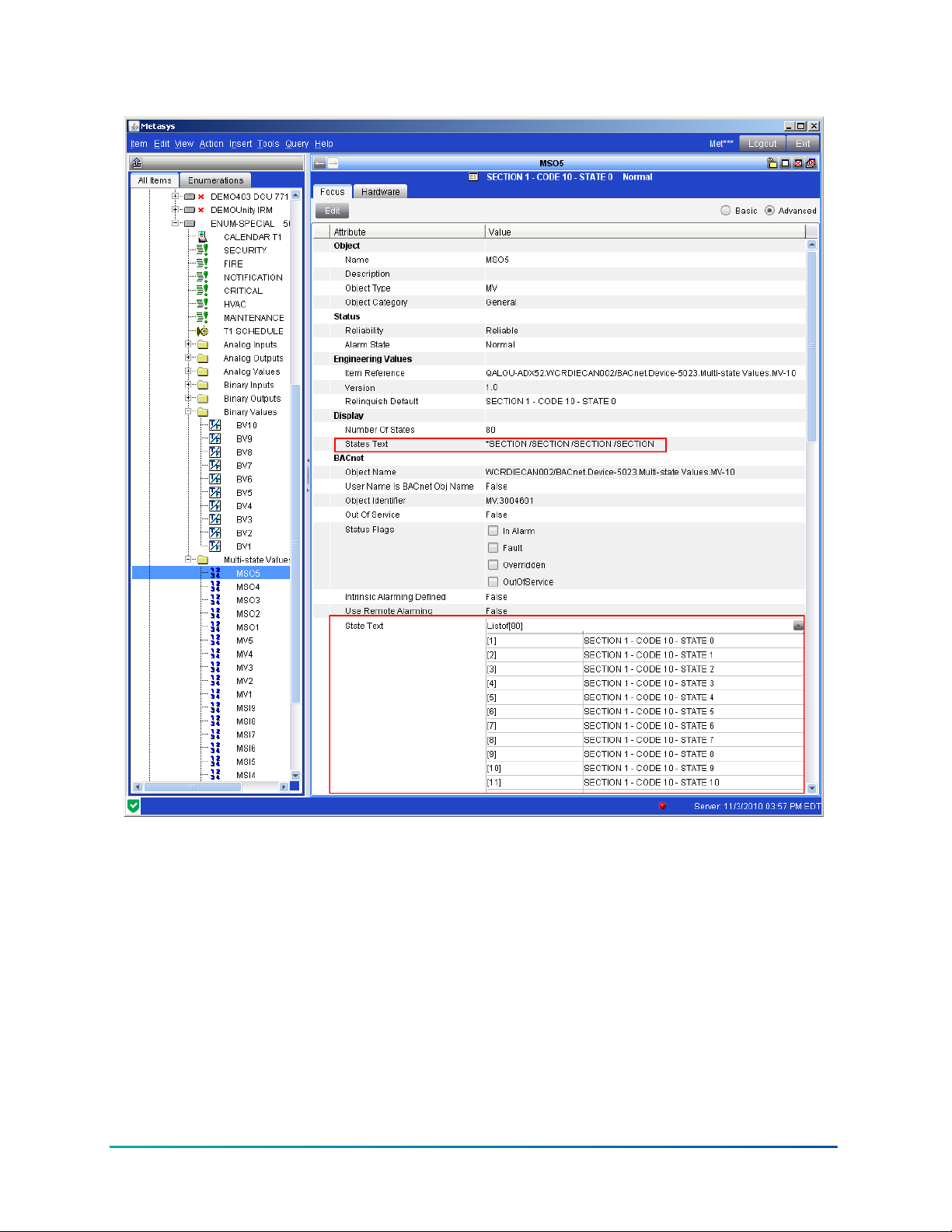
Figure 3: Auto-Created Text for Multistate Variable Objects
After a multi-value BACnet object from a third-party device is mapped to Metasys, in a rare instance
the SMP UI might display its enumeration set ID with the current value of the object (for example,
1031:10 (text not found) Normal). The first number in this example (1031) is the enumeration set
ID and the second number is the enumeration value counting from 0. If you see the current value
of the object represented in this manner, either the UserDictionary on the site is out of sync or the
number of states property at the third party device has changed. To resolve, perform a Rediscover
Text Strings command at the network engine to which the third-party device reports. This action
flushes the locally saved auto-discovered text and updates all objects with the current text.
BACnet Controller Integration Technical Bulletin22
Page 23
Detailed procedures
Connecting to BACnet devices
To connect and integrate BACnet devices into the Metasys system, connect the BACnet devices to
the same IP network as the supervisory controller used for the BACnet system integration.
The devices must have the same BACnet Network Address and BACnet/IP Port number (UDP port)
as assigned to the supervisory controller to which the device is to be integrated. These values can
be seen in the NAE Focus tab.
Exposing BACnet information
About this task:
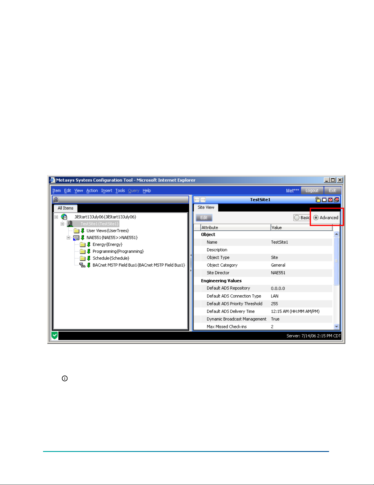
1. Log in to the supervisory controller or open an archive database in the SCT.
2. Right-click the Site Object and select View. The Site View screen appears.
Figure 4: Site view screen
3. On the right side of the Site View screen, click Advanced.
4. Click Edit on the left side of the Site View screen and scroll down to the BACnet section
(Figure 5).
Note: The BACnet section is visible only when the Advanced option is selected.
23BACnet Controller Integration Technical Bulletin
Page 24
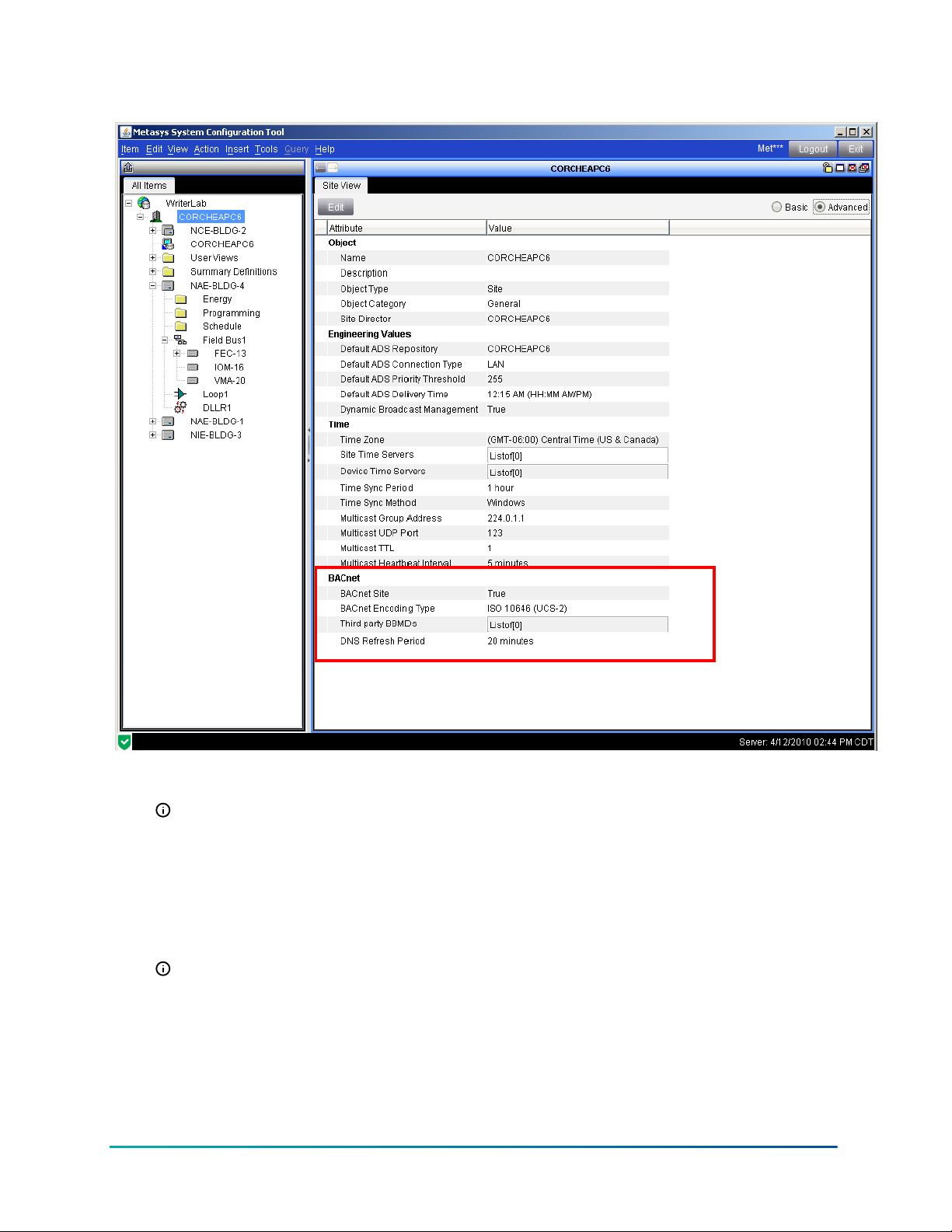
Figure 5: BACnet section enabled in site view
5. Set the BACnet Site field to True and set the BACnet Encoding Type for the encoding used
by the BACnet devices.
Note: The default BACnet Encoding Type is UTF-8. Many BACnet devices, including the
N30 Supervisory Controller, use ASCII for the BACnet Encoding Type. When connecting
to an N30 Network, choose ANSI X3.4 (US_ASCII) for the BACnet Encoding Type.
Many devices supplied in Japan use Microsoft DBCS code page 932 (Japanese Shift JIS).
If connecting to another BACnet device, verify the BACnet Encoding Type with the
manufacturer or supplier of the device. Selection of the wrong BACnet Encoding Type
can result in unaccepted entries of text at the BACnet device, such as failed BACnet
object descriptions and alarm acknowledgments from the Metasys system UI.
Note: The UTF-8 BACnet Encoding Type is also compatible with ASCII as long as
extended characters (for example, Çä╣ß ) are not used with ASCII devices.
6. Click Save. The NAE is now enabled to work with BACnet networks.
Adding a BACnet Integration object
About this task:
BACnet Controller Integration Technical Bulletin24
Page 25
The following process is applicable to online configuration in the Site Management Portal UI or
offline configuration in the SCT. These procedures assume both an online configuration and a
connection between the NAE and the same network as the BACnet system or the integrating
devices.
The SCT contains no Engineering or Diagnostics views, as these are online features. In addition, to
use Auto Discovery, the system must be online and connected to a BACnet network of devices.
Note: At startup of the supervisory controller, the BACnet Integration binds with the BACnet
OID and uses the IP address from that bind. If you move a device to a different subnet,
change the IP address of the device, or change the device's BACnet OID, you must restart the
supervisory controller to bind the BACnet OID with the new IP address.
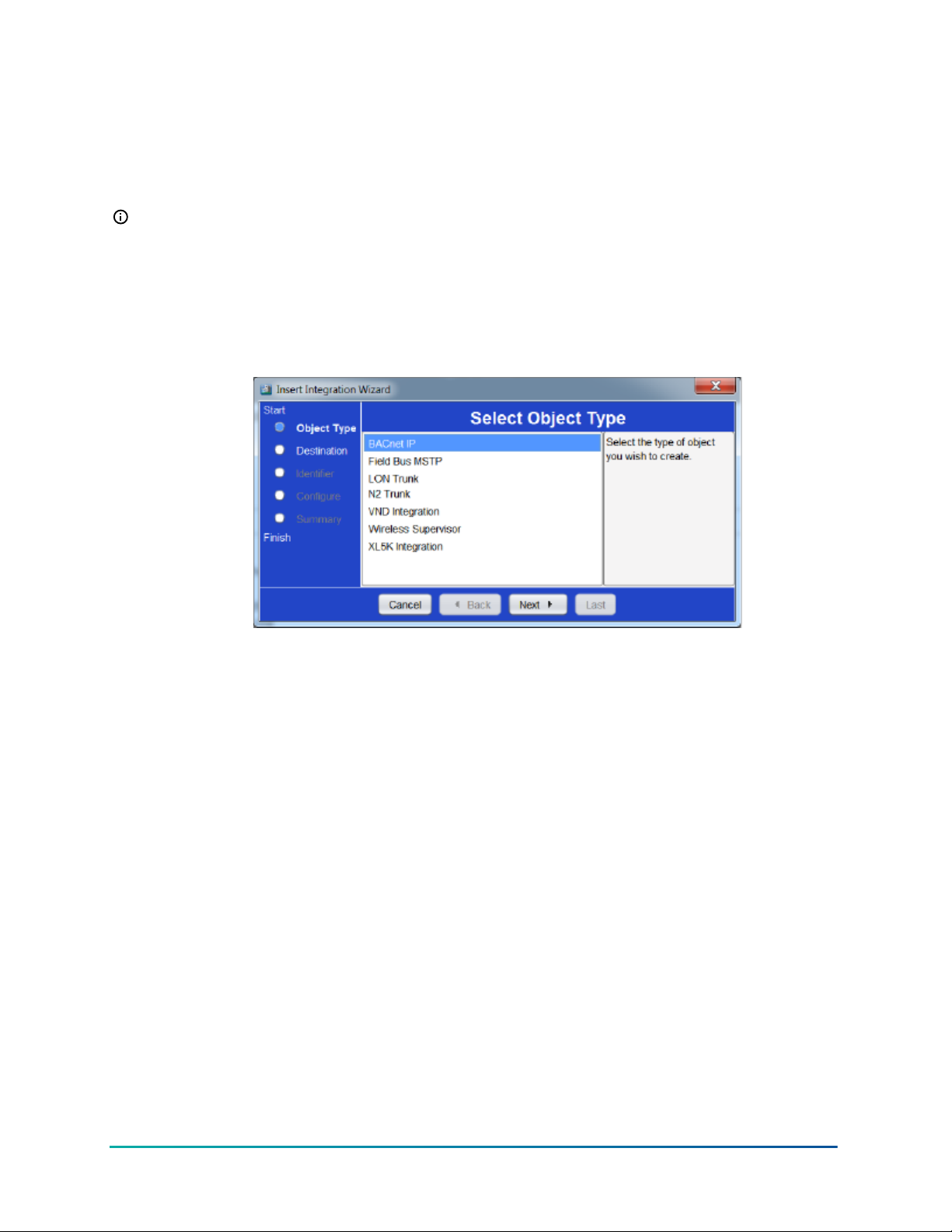
1. On the Insert menu, select Integration. The Insert Integration Wizard, Select Object Type
screen appears.
Figure 6: Insert Integration Wizard (Select Object Type)
2. Select BACnet IP and click Next. The Destination screen appears.
3. Select the NAE/SNx to which to add the BACnet Integration object. After selecting the device,
click Next. The Identifier screen appears.
4. Enter a unique name for the BACnet network of devices to integrate and click Next. The
Configuration screen appears.
5. In most cases, accept the default Configuration parameters. (Refer to the BACnet Integration
object in Metasys SMP Help (LIT-1201793) for a complete definition of the parameters.) Click
Next to accept the defaults. The Summary screen appears.
6. To change anything, click Back. If the Summary looks acceptable, click Finish to create the
BACnet Integration object. You can now add extensions to the new object.
7. Add extensions as desired and click Done when finished. The Wizard closes.
25BACnet Controller Integration Technical Bulletin
Page 26

Figure 7: Ethernet IP Datalink Integration
8. After adding a BACnet Integration object, map the BACnet devices on the network to the
NAE. Verify that the network address and port for this integration match the devices you are
adding to this integration. See Figure 7.
Mapping BACnet/IP Devices using Auto Discovery
About this task:
1. Select the BACnet Integration object within the supervisory controller.
2. On the Insert menu, select Field Device. The Insert Field Device Wizard, Destination
screen appears. Select the BACnet Integration item and click Next. The Insert Field Device
Wizard, Select Definition Mode screen appears.
Note: If no BACnet Integration object appears, follow the procedures in Adding a BACnet
Integration object.
3. Select Assisted and click the Invoke Auto Discovery bar. The Wizard Auto Detect Utility
starts. If auto discovery has not already been performed, it begins immediately. If the Wizard
Auto Detect Utility does not start automatically, click Restart.
BACnet Controller Integration Technical Bulletin26
Page 27

Note: The supervisory controller must be online with the devices on the BACnet/IP
network to use Auto Discovery. When Auto Discovery is complete, a list of discovered
devices appears.
Figure 8: Auto Detect Utility screen
4. Select a device from the list to start the item creation process for that device.
5. Follow the wizard’s prompts. At the configuration screen of the BACnet device, the Instance
Number, Name, and Item Reference fields fill in automatically with the auto-discovered
data from the BACnet device. The Item Reference comes from the remote device BACnet
Object Identifier, and the Name defaults to the BACnet Object Name of the BACnet device
object. The NAE Navigation Tree uses the Name. Change the Name field manually, if desired,
by clicking the Edit button. The BACnet Object Name in the device is not changed.
6. Complete the Insert Field Device screens by accepting the defaults. The Add Extensions
Wizard starts.
7. Add extensions by clicking New for the desired extension and completing the wizard prompts
that appear.
Note: Adding extensions to attributes of the BACnet device is uncommon so most users
can skip this step.
8. When finished adding extensions, click Done. The Insert Field Points Wizard starts.
9. Go to Mapping BACnet Field Points using Auto Discovery or Mapping BACnet Field Points
manually.
Mapping BACnet/IP devices manually
1. Select the BACnet Integration object within the supervisory controller.
2. On the Insert menu, select Field Device. The Insert Field Device Wizard, Destination
screen appears. Select the BACnet Integration item and click Next.
Note: If no BACnet Integration object appears, follow the procedures in Adding a BACnet
Integration object.
3. Select Manual and click Next.
27BACnet Controller Integration Technical Bulletin
Page 28

4. Follow the wizard’s prompts. At the configuration screen of the BACnet device:
- Fill in the Instance Number manually.
- Fill in the Name field manually if the default data for the BACnet device is not
satisfactory.
The Navigation Tree uses the field device name. Change the Name field manually,
if desired, by clicking the Name field. The BACnet Object Name in the device is not
changed.
5. Complete the Insert Field Device screens by accepting the defaults. The Add Extensions
Wizard starts.
6. Add extensions by clicking New for the desired extension and completing the wizard prompts
that appear.
7. When finished adding extensions, click Done. The Insert Field Points Wizard starts.
Note: If no BACnet Integration object appears, follow the procedures in Adding a BACnet
Integration object.
8. Go to Mapping BACnet Field Points using Auto Discovery or Mapping BACnet Field Points
manually.
Mapping BACnet Field Points using Auto Discovery
About this task:
Once one or more BACnet devices are configured, add BACnet field points that are mapped to
BACnet objects in the BACnet device.
The supervisory controller must be online with the devices on the BACnet/IP network to use Auto
Discovery. For mapping points offline, see Mapping BACnet Field Points manually.
1. On the Insert menu, select Field Points. The Insert Point Wizard, Destination screen
appears.
Figure 9: Insert Point Wizard (Destination)
The Insert Field Points Wizard starts automatically after inserting a Field Device.
Because it selects the newly added device as the destination, the wizard opens to the
Select Definition Mode screen bypassing the Destination screen.
Add BACnet devices during the Mapping BACnet Field Points using Auto Discovery
procedure. To view the selectable devices, click the plus sign next to the BACnet
Integration object to open the list of mapped BACnet devices.
2. Select the BACnet device to which objects are to be integrated and click Next. The Insert
Point Wizard, Select Definition Mode screen appears.
BACnet Controller Integration Technical Bulletin28
Page 29

3. Click Assisted and then click Invoke Auto Discovery. The Wizard Auto Detect Utility starts.
If an auto discovery has not already run, it begins immediately. If the Wizard Auto Detect
Utility fails to start automatically, click Restart.
When Auto Discovery finishes, a list of discovered BACnet objects appears. The fields
automatically fill in with the auto discovered data from the BACnet device. The Native
Object Name is the BACnet Object Name in the device.
Note: If the total number of discovered points exceeds the limit, then the returned
discovery indicates Page 1 of X, where X is the total number of pages. A restart
increments the page and displays the next set of discovered points. Each completion
of the point mapping process also increments the page. After the last page, the point
mapping process begins again at Page 1.
Figure 10: Auto Detect Utility screen
The Identifier derives from the remote device BACnet Object Identifier and indicates
both the object type and instance number. The Name defaults to the Native BACnet
Object Name; you can change the Name field during the configuration process if
desired. The Name appears in the navigation tree. The BACnet Object Name in the
device is unchanged. The Instance Number comes from the BACnet Object Identifier.
4. Close the window by clicking the X in the upper-right corner of the screen.
29BACnet Controller Integration Technical Bulletin
Page 30

5. When the auto discovery window is closed, the point mapping utility dialog box appears as
shown in Figure 11. The Assisted Identity/Configure screen appears. Use this screen to
select which points to map from the BACnet device.
Figure 11: (Part 1 of 2) Insert Point Wizard (Assisted Identity/Configuration)
6. Select points individually by double-clicking on them, or use the Map All function. When an
item is selected to be mapped, a green check mark appears next to it, and the right side of
the screen displays a summary of the mapping items. A blue check mark represents an item
that has been previously mapped.
Note: Deselecting a folder in the tree does not deselect the objects under the folder.
Use this feature if the objects should appear directly under the controller in the
navigation tree. Map All is not recommended. Mapping objects that you do not need will
impact performance.
BACnet Controller Integration Technical Bulletin30
Page 31

Figure 12: (Part 2 of 2) Insert Point Wizard (Assisted Identity/Configuration)
7. After selecting all the points to map, click Next. The Insert Point Wizard summary screen
appears.
8. Review the Summary screen and click Finish.
Mapping BACnet Field Points manually
After adding a BACnet device, add BACnet Field Points mapped to BACnet objects in the BACnet
device, if desired.
1. On the Insert Menu, select Field Points. The Insert Point Wizard, Destination screen
appears (Figure 9).
The Insert Field Points Wizard starts automatically after inserting a Field Device. Because
it selects the newly added device as the destination, the wizard opens to the Select
Definition Mode screen, bypassing the Destination screen.
2. Select the BACnet device from which to map the points and click Next. The Insert Point
Wizard, Select Definition Mode screen appears.
Note: Add BACnet devices during the Mapping BACnet/IP Devices using Auto Discovery
procedure in this document. If the screen displays no selectable device, click the plus sign
next to the BACnet Integration object to open the list of mapped BACnet devices.
3. Select Manual point definition; the screen changes to the manual mode with a list of point
object types to add.
31BACnet Controller Integration Technical Bulletin
Page 32

Figure 13: Insert Point Wizard (Select Definition Mode)
Distinguish the Manual point definition from the Assisted point definition by the list of steps
on the left side of the screen. The Manual definition display adds a Data Source step and
separates the Identify and Configure steps.
4. Select the type of point to create and click Next. The remaining steps of the Insert Point
Wizard - manual mode are listed in the following table.
BACnet Controller Integration Technical Bulletin32
Page 33

Table 6: Insert Point Wizard - manual mode screens
Screen Purpose
Select the Data Source
Identifier Allows entry of a unique name for each mapped
Configure Allows field point configuration. Click Advanced
Summary Provides a summary of the entered information.
5. Click Finish.
Enter the Instance Number associated with the
point you are mapping.
field point.
to see the BACnet object identifier. Be sure to
fill in the Instance Number on the Hardware
tab of the Configuration screen and to match
the configuration to the Instance Number of
the BACnet Object Identifier in the host BACnet
device.
Click Back to make any corrections.
Using the Relearn feature
About this task:
The Relearn feature uses Auto Discovery and requires that the supervisory controller be online with
the BACnet network to discover Field Devices and Field Points.
1. Select the BACnet Integration object from the Navigation tree.
2. Click the Engineering tab and click the Relearn button that appears below the tab.
3. Discovery begins automatically and finds all new BACnet devices on the network. After
Discovery, the new devices appear in the Integration Tree and in the Integration View.
4. When Discovery is complete, close the Auto Discovery box.
Using the Engineering view to View and Edit Device Attributes (BACnet Properties)
About this task:
When online with a BACnet device, use the Engineering view of the BACnet Integration object
to View and Edit Device Attributes (known as properties in BACnet terms). Act on these devices
whether or not the BACnet devices have been mapped to the Navigation tree.
1. Right-click the BACnet Integration object on the Navigation tree and select View. The BACnet
Integration object appears.
2. Click the Engineering tab, and navigate to either a field device or a field point in the
Integration Tree.
3. Double-click the selected field device or field point. The Details screen for the selected field
device or object appears.
4. Click Edit. The editable fields from this screen appear in a box with a heavy line border.
The BACnet device displays only the required and optional attributes of the BACnet
point object. Vendor-specific proprietary attributes do not appear.
For attributes that support a command priority, such as the Present Value of an Analog
Output (AO), the BACnet device displays the active value and priority. To change a
33BACnet Controller Integration Technical Bulletin
Page 34

value, enter an equal or higher priority. Clearing the value at the specified priority
releases this priority and displays the value for the next highest priority.
5. Make the desired changes and click Save.
Field Bus Integration object — detailed procedures
Adding BACnet MS/TP (Field Bus) Integrations
1. On the Insert menu, click Integration. The Insert Integration Wizard starts.
2. Follow the prompts to configure the integration using the information in the following table.
Table 7: Insert Integration Wizard
Screen Purpose
Object Type Select the type of integration, Field Bus MSTP.
Destination Select the network engine that connects to the
integrating trunk.
Identifier Type a unique name for the trunk. Each
integration under a device requires a unique
name. By default, the name of the newly
entered object has a number appended to keep
it unique; therefore, if adding a BACnet MS/TP
Configure
trunk to a device for the first time, the default
name is Field Bus.
22
Configure information about the integration
such as trunk number33 and a brief description.
11
1
Note: If BACnet routing is enabled for this
network engine, the Network Address on
the Hardware tab must be unique from
all other Field Bus and BACnet/IP network
addresses on the site.
Summary View the basic parameters of the integration
just added.
1 The local MS/TP trunks are 1 and 2. Some supervisory products support two MS/TP trunks. Numbers greater then 2
are for a remote field bus. When selecting or adding a second BACnet MS/TP trunk, change the default trunk number
(which is 1) on the Hardware tab to 2 and change the Network Address to a value not already used on the network
engine, typically one greater than the default value.
2 Typically, use the default values for Baud Rate Selection and Network Address. Change the Network Address if the
activity at the site also includes integrating third-party BACnet networks into the network engine. If BACnet routing is
enabled for this network engine, the Network Address on the Hardware tab must be unique from all other network
addresses on the site.
3 Trunk numbers 1 and 2 are used for local directly wired BACnet MS/TP trunks. Trunks that communicate through the
BACnet IP connection to a BACnet/IP to MS/TP router (which provides the MS/TP wiring connection) use higher trunk
numbers between 3 and 20. You must configure the router with an MS/TP network address number that is unique from
all other network address numbers on the site. You must set the BACnet network address of the field bus to match the
BACnet MS/TP network address number of the router. The BACnet/IP network address of the router must match the
BACnet/IP network address of the NxE. In addition, one or more BBMDs may be required to allow BACnet/IP broadcast
messages to reach the router. For more information on field bus capacity and quantity limits, refer to Metasys® SMP
Help (LIT-1201793).
3. Click Finish.
BACnet Controller Integration Technical Bulletin34
Page 35

Manually adding BACnet MS/TP (Field Bus) Field Devices (online or offline)
About this task:
Use the Insert Field Device Wizard to manually add BACnet MS/TP (field bus) field devices,
whether the system is online or offline.
1. On the Insert menu, click Field Device. The Insert Field Device Wizard starts.
2. Select the trunk to which the field device is connected and click Next. The Insert Field Device
Wizard Select Definition Mode screen appears.
3. Click Manual. You are then prompted to select the class of device (JCI Family BACnet Device
or General BACnet Device).
Note: When using the SCT, the Assisted option appears dimmed because that method
is unavailable when the system is offline. When devices and objects are added in SCT,
mapper instance numbers are not assigned. The Supervisory Device assigns instance
numbers to mapper objects when archive is loaded. If you add devices or objects in
SCT, upload the Supervisory Device back into SCT to capture mapper instance numbers.
Failure to upload could result in conditions where mapper instance numbers could
change.
4. For JCI Family BACnet Device, select a BACnet MS/TP address for the new device. All BACnet
MS/TP addresses in the list are available because the address list updates each time a
new controller object is created. After choosing a BACnet MS/TP address, click Next. Auto
Discovery is available only for online field devices. See the Adding BACnet MS/TP Field Devices
online using Auto Discovery section in this document.
Note: With JCI Family BACnet Device selected, you are prompted to enter the MAC
Address, which is the physical hardware address of the device as determined by its
address switch settings. With General BACnet Device selected, you must enter the
BACnet Instance Number, which is determined by software settings in the device. This
value is entered on the Hardware tab of the Identifier screen of the Wizard.
5. Click Next. The Insert Field Device Wizard Identifier screen appears.
6. Choose a unique name (within the parent object) for the new controller object and click
Next. The Insert Field Device Wizard Configure screen appears. The fields of the Configure
screen have default data based on the previous information entered. This information
includes the object type and naming parameters of the new controller just created.
35BACnet Controller Integration Technical Bulletin
Page 36
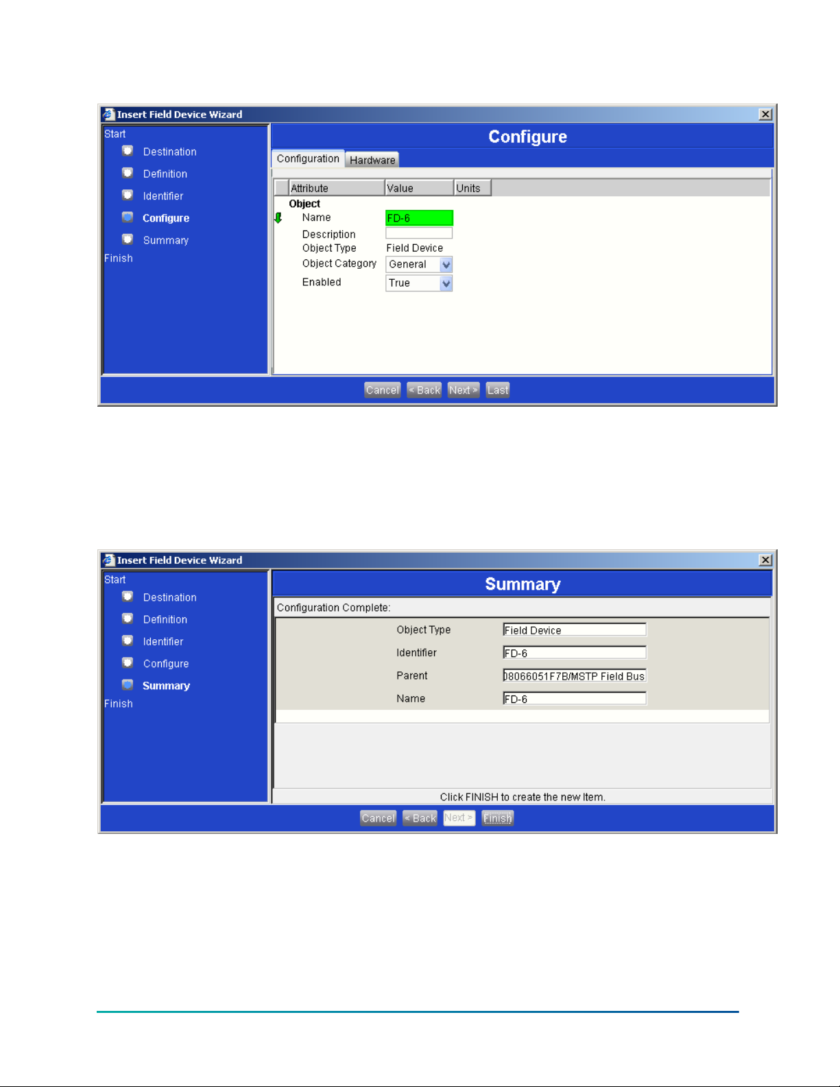
Figure 14: Insert Field Device Wizard (Configure screen)
When using the Manual device definition, the default name is always FD plus an
incremental number for field devices. The incremental number provides a suggested
name that is unique within the context of the parent object, in this case a BACnet MS/
TP (field bus) integration.
7. Click Next. The Insert Field Device Wizard, Summary screen appears.
Figure 15: Insert Field Device (Summary screen)
8. If satisfied with the Summary, click Finish (otherwise, click Back and correct any problems).
9. Add extensions to the newly created controller object, if needed. See Adding extensions to an
object for more information.
BACnet Controller Integration Technical Bulletin36
Page 37
Adding BACnet MS/TP Field Devices online using Auto Discovery
About this task:
When logged in to a network engine through the Metasys system, you can automatically discover
field devices. SCT does not support the Auto Discovery process. However, with SCT you can upload
devices discovered on the network and added to the NAE database for archive and editing.
1. On the Insert menu, select Field Device. The Insert Field Device Wizard Destination screen
appears.
2. Select the BACnet MS/TP trunk to map the field devices to and click Next. The Select
Definition Mode screen appears.
The Assisted Mode and Invoke Auto Discovery options are not available from the SCT.
Upload any relevant online-generated information to an archive database in the SCT.
3. Click Invoke Auto Discovery. The Auto Detect Utility starts.
4. After Auto Discovery is complete, select the device to map. If the device is already mapped, a
notification message appears. If the device is not mapped, the Insert Field Device Identifier
screen appears.
5. Enter a unique identifier for the device and click Next. The Insert Field Device Wizard
Configure screen appears.
6. Click Next. The Insert Field Device Summary screen appears.
7. If the Summary is satisfactory, click Finish (otherwise, click Back and correct any problems).
This action creates the object and enables the process for adding extensions to the new
controller object. See Adding extensions to an object for more information.
8. After adding all discovered devices, use the SCT to upload the NAE database to an archive
database in the SCT.
Note: See Troubleshooting (BACnet Trend Logs cannot be discovered) if the auto
discovery fails to find third-party Trend Log objects.
Adding BACnet Devices to the BACnet and MSTP Integrations using the Import Integration Wizard
About this task:
1. On the navigation tree, click the integration you want to add a device to.
2. On the Action menu, select Import Integration. The Open files screen appears.
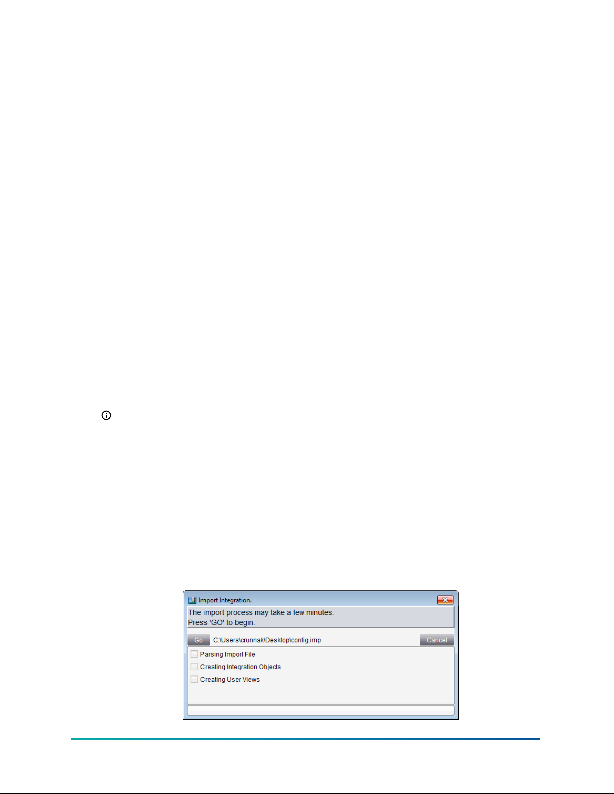
3. Locate and select the import file that matches the integration. Then click Open. The Import
Integration screen appears.
Figure 16: Import Integration Screen
37BACnet Controller Integration Technical Bulletin
Page 38

4. Click Go. The Import Integration starts.
5. After the Import Integration is complete, a notification message appears.
If the import file does not match the integration, an Alert notice appears.
6. Click OK. Repeat this process for each device you want to add.
Adding extensions to an object
About this task:
Add trend, totalization, alarm, load, and averaging extensions to increase the functionality of a field
device or field point object.
After creating a field device object or a field point object, the Extension Wizard automatically starts
(skip to Step 3).
1. Select an object.
2. On the Action menu, select Show Extensions. The Extension Wizard starts.
3. Click New in the row next to the desired type of extension. Follow the prompts on the Wizard
that appears. See Adding a Trend Extension, Adding a Totalization Extension, or Adding an
Alarm Extension for more information.
4. Follow the prompts to configure the extension and click Finish when done. The Extension
Wizard appears with the new extension listed in the appropriate row.
5. Click Done after adding the needed extensions. If the Extension Wizard launches
automatically after creating the new field device object, the Field Device Extension screen
opens next.
6. Add field points under the newly created controller object by clicking New in the Field Points
panel of the Field Device Extension Wizard. See Manually adding BACnet MS/TP (Field Bus)
Field Devices (online or offline) for instructions on adding BACnet MS/TP points.
Adding a Trend Extension
About this task:
Adding trend extensions to objects allows the user to collect historical data for one or more
attributes of an object. Afterwards, view that data or forward the data to a Metasys Application
Server for long-term storage. Use Trend Study to view Trend extensions from multiple items at the
same time.
1. In the Extensions Wizard, click New in the Trend row. The Insert Trend Wizard Select
Attribute screen appears.
The trended attribute defaults to Present Value. To trend a different attribute, click
other. The attribute list appears.
BACnet Controller Integration Technical Bulletin38
Page 39

Figure 17: Insert Trend Wizard (Select Attribute Screen)
2. Select an attribute and follow the prompts in the Wizard to complete the addition of a Trend
Extension.
3. Click Finish. The Extensions Wizard appears with the new attribute listed under Trend.
Adding a Totalization Extension
About this task:
1. In the Extensions Wizard, click New in the Totalization row. The Insert Totalization Wizard
Select Attribute screen appears.
39BACnet Controller Integration Technical Bulletin
Page 40

Figure 18: Insert Totalization Wizard (Select Attribute Screen)
2. Select an object in the top of the screen and an attribute in the bottom and click Next.
Note: Click other to display a list of available attributes.
3. Select Totalization type from the available options on the right (if available).
4. Follow the prompts in the Wizard to complete the addition of a Totalization Extension.
5. Click Finish. The Extensions Wizard appears with the new attribute listed under the
Totalization tab.
Adding an Alarm Extension
About this task:
Note: To add a BACnet intrinsic alarm, refer to the M-Series Workstation Interface to the NAE
Application Note (LIT-1201655).
1. In the Extensions Wizard, click New in the Alarm row. The Insert Alarm Wizard Select
Attribute screen appears.
BACnet Controller Integration Technical Bulletin40
Page 41

Figure 19: Insert Alarm Wizard (Select Attribute Screen)
2. Next.
Note: Click other to display a list of available attributes. Select an object in the top of
the screen and an attribute in the bottom of the screen and click
3. Follow the prompts in the Wizard to complete the addition of an Alarm Extension.
4. Click FinishSelect an object in the top of the screen and an attribute in the bottom of the. The
Extensions Wizard appears with the new attribute listed under the Alarm tab.
Adding a Load Extension
About this task:
1. In the Extensions Wizard, click New in the Load row. The Insert Load Wizard Select
Attribute screen appears.
2. Select an object in the top of the screen and an attribute in the bottom of the screen and click
Next.
Note: Click other to display a list of available attributes.
3. Follow the prompts in the Wizard to complete the addition of a Load Extension.
4. Click Finish. The Extensions Wizard appears with the new attribute listed under Load.
41BACnet Controller Integration Technical Bulletin
Page 42

Adding an Averaging Extension
About this task:
1. In the Extensions Wizard, click New in the Averaging row. The Insert Averaging Wizard
Select Attribute screen appears.
Figure 20: Insert Averaging Wizard (Select Attribute Screen)
2. Select an object in the top of the screen and an attribute in the bottom of the screen and click
Next.
Note: Click other to display a list of available attributes.
3. Follow the prompts in the Wizard to complete the addition of an Averaging Extension.
4. Click Finish. The Extensions Wizard appears with the new attribute listed under Averaging.
Deleting extensions from an object
About this task:
1. Select a field device or a field point that contains the extensions to delete.
2. On the Action menu, select Show Extensions. The Extension Wizard starts.
3. Select the check boxes next to the extensions you want to delete.
4. Click Delete for each extension.
Clicking Delete in any extension row deletes only the checked extensions in that row.
For example, in the Extension Wizard, click both Resource Delete and Alarm Delete to
delete both checked extensions.
5. Click Done when finished.
Copying extensions to a Field Device or Field Point (offline only)
About this task:
1. Select a field device or a field point that contains the extensions to copy.
2. On the Action menu, click Show Extensions. The Extension Wizard starts.
BACnet Controller Integration Technical Bulletin42
Page 43

3. Select the check boxes for the extensions that you want to copy and click Copy Checked
Extensions at the bottom of the Wizard.
4. Click Done.
5. In the Navigation Tree, select the desired field device or field point destination.
6. On the Edit menu, click Paste. This adds the copied extensions to the selected field device or
field point.
7. Drag the field device or field point to the Display frame (on the right) to verify that the new
extensions are correct.
Enabling the routing mode
Normally, third-party BACnet/IP field devices only view mapper objects in the supervisory
controller, which are representations of the real BACnet objects in the integrated third-party
BACnet field devices. Because the mapper objects are representations the supervisory device keeps
updated, no extra network traffic is added to third-party BACnet field devices. Enable the routing
mode at the supervisory controller only if you need to communicate directly with the third-party
BACnet field devices, such as when you are reprogramming from the third party’s engineering
workstation, to directly pass BACnet messages from the workstation through the supervisory
controller to the third-party BACnet field devices.
BACnet routing considerations
BACnet routing is a technique by which data on one physical Data Link layer is passed to and from
another physical Data Link layer. In the case of the network engine, this BACnet routing occurs
when data is passed from the IP side of the device to the MS/TP side of the device.
If routing is disabled, the network engine provides an indirect (or proxy) method of obtaining the
data on its MS/TP network when a request is made from another device on the IP side of the device.
With routing enabled, the network engine may no longer need detailed knowledge of the types of
devices and services that reside on its MS/TP network–it simply passes the data request from one
link to the next and back again with as little interference as possible. This passing of information
benefits those third-party vendors that have the need to directly access devices on the network
engine’s MS/TP network using tools from the IP network side.
Note: On a homogenous (or near-homogeneous) Johnson Controls network, you do not need
to enable routing. Enabling routing requires the entire site to follow strict BACnet rules so the
consequences should be fully understood beforehand.
The routing function of the network engine is disabled by default. Routing can be enabled by
setting the Routing Mode attribute on the Network tab of the Device object view to Enabled. You
can disable routing by setting the Routing Mode attribute to Disabled. Restarting the network
engine is not required when routing is enabled or disabled.
The Enable without Broadcasts setting of the Routing Mode attribute is used to reduce the network
traffic caused by enabling routing on an MS/TP network. If this option is used, it is difficult for thirdparty devices outside the network to discover any devices on a routed network using this setting
because they rely on broadcast data for discovery. Because the data capacity of Ethernet IP is much
higher than that of MS/TP, special care must be taken to avoid overloading the MS/TP bus when
routing is enabled.
All integrated points are visible in the network engine by default, including General BACnet Devices.
A third-party device can view the entire list of integrated points by requesting the Object List of the
network engine. This request is part of the BACnet communication protocol used to help discover
objects on other BACnet devices.
43BACnet Controller Integration Technical Bulletin
Page 44

If you want to have access to third-party integrated points within the network engine, there is a
benefit to interfacing with mapped MS/TP points in the network engine rather than directly with the
objects in each MS/TP device. The network engine acts as a high-speed proxy for all data requests
within its domain, which ensures the best performance. This is the default behavior for the network
engine and eliminates the need for enabling routing on the network engine. Routing should only be
enabled if existing third-party tool configurations cannot support any other method.
When routing is enabled, device configurations must follow more strict setup rules, and
configurations that may have previously worked in non-routing situations may no longer work. The
same setup rules apply for systems with routing enabled and static IP networks.
Notes:
• Once routing is enabled on the network engine, all device identifiers within each device must
be unique across all routed networks, and all network address numbers must be unique across
all routed networks.
• Be sure you have good reason before you enable routing. For example, if BACnet rules are not
followed when routing is enabled, performance and intermittent issues could result. Or, if a
third-party device exists or is added in the future, considerable work may be required to allow
the device to work.
The BACnet Broadcast Receive Rate, BACnet Routed Messages Rate, MS/TP Broadcast Transmit
Rate, MS/TP Broadcast Receive Rate, and Net Routed Messages attributes allow you to diagnose an
overloaded network.
Related documentation
The following table lists documents related to Metasys system and BACnet® protocol.
Table 8: Related documentation
For information on: See Document
Installing the NxE55
Installing the NxE35 and NxE45
Installing the SNC
Installing the SNE
Installing the NCE
Overview of BACnet and MS/TP Field Bus
Controllers
Setting up Databases Metasys SCT Help (LIT-12011964)
Configuring the NAE and NCE NAE Commissioning Guide (LIT-1201519)
Understanding the Metasys System
NAE55/NIE55 Installation Instructions (Part No.
24-10051-43)
NAE35/NAE45 Installation Instructions (Part No.
24-10050-6)
SNC Network Engine Installation Instructions (Part
No. 24-10143-01892)
SNE Network Engine Installation Instructions (Part
No. 24-10143-01647)
NCE25 Installation Instructions (Part No.
24-10143-63)
Metasys System Field Equipment Controllers and
Related Products Product Bulletin (LIT-12011042)
Metasys System Configuration Guide
(LIT-12011832)
SNE Commissioning Guide (LIT-12013352)
SNC Commissioning Guide (LIT-12013295)
NAE85 Commissioning Guide (LIT-12011044)
BACnet Controller Integration Technical Bulletin44
Page 45

Table 8: Related documentation
For information on: See Document
Using the Metasys System and Metasys System
Supported Objects and Commands
NAE Protocol Implementation Conformance
Statement (PICS)/BACnet Interoperability
Building Blocks (BIBBs)
SNE/SNC Protocol Implementation
Conformance Statement (PICS)
BACnet Information
Supported Enumeration Sets When Using the
Metasys System with a Third-Party BACnet
Workstation or Controller
Acronyms and Terms
Remote Field Bus
Open Data Server ODS Commissioning Guide (LIT-12011944)
Open Application Server
Metasys Site Management Portal Help
(LIT-1201793)
NAE/NCE Protocol Implementation Conformance
Statement (LIT-1201532)
SNE/SNC Protocol Implementation Conformance
Statement (LIT- 12013355
American National Standards Institute/
American Society of Heating, Refrigerating,
and Air-Conditioning Engineers (ANSI/ASHRAE)
Standard 135-2019 at protocol revision 18
Metasys System Enumeration Sets Technical
Bulletin (LIT-12011361)
Metasys System Extended Architecture Glossary
Technical Bulletin (LIT-1201612)
MS/TP Communications Bus Technical Bulletin
(LIT-12011034)
Open Application Server (OAS) Commissioning
Guide (LIT-12013243)
Troubleshooting
BACnet System Integration troubleshooting guide
Use the information in Table 9 to assist in diagnosing and solving possible BACnet System
Integration problems.
45BACnet Controller Integration Technical Bulletin
Page 46

Table 9: BACnet System Integration Troubleshooting Guide
Symptom Cause Solutions
The network engine
Field devices appear
to periodically cycle
online and offline to
the network engine as
reported on the Site
Management Portal
UI. However, the field
devices may actually be
online the entire time
is too busy with
some other tasks,
misses a token pass,
and is dropped from
the token loop. By
the time the engine
rejoins the token
loop, the engine
has already flagged
its field devices as
Refer to the section Adjusting NAE network
sensitivity in the NAE Commissioning Guide
(LIT-1201519).
offline.
BACnet Controller Integration Technical Bulletin46
Page 47

Table 9: BACnet System Integration Troubleshooting Guide
Symptom Cause Solutions
Auto discovery fails to
find all devices.
—
Verify that the supervisory controller's Network
Address and BACnet IP Port match that of the
integrating IP-based BACnet devices. In the Device
object Focus view, select Advanced to view the
BACnet IP Port address.
If the BACnet device is on the MS/TP Field Bus,
verify that the Network Address defined under the
Hardware tab of the MS/TP Field Bus is correct.
Verify that no network devices have duplicated
Object Identifiers. In accordance with the BACnet
specification, the BACnet Object Identifier for
each device on the entire network must be
unique. After performing a Relearn, view the
Duplicate Device Identifiers attribute of the
BACnet Integration object (Diagnostic view). Any
duplicates found on the network are listed.
Note: Duplicates of VMA1930 and FAC4911
devices will be included in list of discovered
devices.
Verify that the BACnet Object Identifier of the
supervisory controller itself does not conflict with
that of the BACnet devices being integrated. The
BACnet Object Identifier appears in the Focus
view after selecting Advanced.
When Dynamic Broadcast Managment is enabled
at the Site Director:
If the BACnet device is on a different IP network
segment from any supervisory controller, specify
a BACnet Broadcast Management Device (BBMD)
for its segment. Add the device IP of a BBMD
device in that segment to the third-party BBMD
attribute of the Site object.
When Dynamic Broadcast Management is
disabled at the Site Director:
Add all of the specified BBMD devices to the
BBMD list of each JCI supervisory, field controller,
or third party BBMD device. With Release 11.0
Metasys supervisory devices, you can enter either
an IP address or a host name.
Verify that the BACnet device supports the WhoIs BACnet service. Auto discovery requires the
support of this service.
47BACnet Controller Integration Technical Bulletin
Page 48

Table 9: BACnet System Integration Troubleshooting Guide
Symptom Cause Solutions
A BACnet device goes
offline and fails to come
back online.
A change of the
BACnet device IP
address.
At startup of the supervisory controller, the
BACnet Integration binds with the BACnet Object
Identifier (OID) and uses the IP address from that
bind. If you move a device to a different subnet,
or change the IP address of the device, you must
restart the NxE to bind the OID with the new IP
address.
BACnet Trend Logs
cannot be discovered.
The third-party
Trend Log object
does not support
BACnet Logging
Type (property
197) and returns
an Unknown_
Manually add the third-party Trend Log object
to show the trend log attributes, and display the
views and log data graph properly. See Adding a
Trend Extension.
Property error
when read.
Encoding type may
be incorrect.
Attempts to write string
attributes (such as
Description) or if alarm
Verify that the BACnet Encoding Type specified
in the Site matches the encoding that the BACnet
devices are using: ANSI X3.4 (US-ASCII), ISO 10646
(UTF-8), ISO 10646 (UCS-2), or Microsoft DBCS
Code Page 932.
acknowledgments from
the SMP UI are not seen
at the BACnet device.
Note: The UTF-8 BACnet Encoding Type
is also compatible with ASCII as long as
extended characters (for example, Ç, ä, ╣,
and ß) are not used with ASCII devices.
Time sync or UTC time
sync messages are not
accepted.
— The network engine accepts BACnet time sync
messages only if no Simple Network Time
Protocol (SNTP) server is defined for that network
engine. If the device is a Site Director, do not
enable (leave blank) the Site Time Servers
attribute of the Site object.
or
If the device is not a Site Director, do not enable
(leave blank) the Device Time Servers attribute of
the Site object.
or
If the Time sync or UTC time sync message does
not contain a specific time as required by BACnet
(for example, message has wild card values), it is
not accepted.
BACnet Controller Integration Technical Bulletin48
Page 49

Product warranty
This product is covered by a limited warranty, details of which can be found at
www.johnsoncontrols.com/buildingswarranty.
Software terms
Use of the software that is in (or constitutes) this product, or access to the cloud, or hosted
services applicable to this product, if any, is subject to applicable end-user license, opensource software information, and other terms set forth at www.johnsoncontrols.com/
techterms. Your use of this product constitutes an agreement to such terms.
Patents
Patents: https://jcipat.com
Single point of contact
APAC Europe NA/SA
JOHNSON CONTROLS
JOHNSON CONTROLS
JOHNSON CONTROLS
C/O CONTROLS PRODUCT MANAGEMENT
NO. 32 CHANGJIJANG RD NEW DISTRICT
WUXI JIANGSU PROVINCE 214028
CHINA
WESTENDHOF 3
45143 ESSEN
GERMANY
Contact information
Contact your local branch office: www.johnsoncontrols.com/locations
Contact Johnson Controls: www.johnsoncontrols.com/contact-us
507 E MICHIGAN ST
MILWAUKEE WI 53202
USA
49BACnet Controller Integration Technical Bulletin
Page 50

© 2021 Johnson Controls. All rights reserved. All specifications and other information shown were current as of document
revision and are subject to change without notice.
 Loading...