

Page 1
INSTALLATION MANUAL
VARIABLE SPEED ECM
SINGLE PIECE MULTI-POSITION
AIR HANDLERS
MODELS: A VC SERIES
LIST OF SECTIONS
GENERAL . . . . . . . . . . . . . . . . . . . . . . . . . . . . . . . . . . . . . . . . . . . . . .1
SAFETY . . . . . . . . . . . . . . . . . . . . . . . . . . . . . . . . . . . . . . . . . . . . . . . .1
UNIT INSTALLATION . . . . . . . . . . . . . . . . . . . . . . . . . . . . . . . . . . . . .4
DUCT WORK AND CONNECTIONS . . . . . . . . . . . . . . . . . . . . . . . . .8
COIL METERING DEVICES . . . . . . . . . . . . . . . . . . . . . . . . . . . . . . . .9
REFRIGERANT LINE CONNECTION . . . . . . . . . . . . . . . . . . . . . . . .11
CONDENSATE DRAIN CONNECTIONS . . . . . . . . . . . . . . . . . . . . .12
ELECTRIC HEATER INSTALLATION . . . . . . . . . . . . . . . . . . . . . . .13
LINE POWER CONNECTIONS . . . . . . . . . . . . . . . . . . . . . . . . . . . . .13
LIST OF FIGURES
Return Air Duct Attachment & Component Location . . . . . . . . . . . . . .2
Pressure Check . . . . . . . . . . . . . . . . . . . . . . . . . . . . . . . . . . . . . . . . . .3
Dimensions & Duct Connection Dimensions . . . . . . . . . . . . . . . . . . . .3
Typical Installation . . . . . . . . . . . . . . . . . . . . . . . . . . . . . . . . . . . . . . . .4
Horizontal Pan Adjustment Strap Hole Reference . . . . . . . . . . . . . . . .5
Coil Condensate Deflector Installation . . . . . . . . . . . . . . . . . . . . . . . . .6
Recommended Position of Coil to Install Downflow/Horizontal Right
Condensate Components . . . . . . . . . . . . . . . . . . . . . . . . . . . . . . . . . .7
Installation of Downflow Condensate Diverter Shields . . . . . . . . . . . . .7
60C Horizontal Right Condensate Deflectors . . . . . . . . . . . . . . . . . . .7
60C Horizontal Right Coil Condensate Final Assembly . . . . . . . . . . . .7
Condensate Shield . . . . . . . . . . . . . . . . . . . . . . . . . . . . . . . . . . . . . . . .8
Horizontal Suspension . . . . . . . . . . . . . . . . . . . . . . . . . . . . . . . . . . . . .9
Duct Attachment . . . . . . . . . . . . . . . . . . . . . . . . . . . . . . . . . . . . . . . . . .9
Duct Work Transition . . . . . . . . . . . . . . . . . . . . . . . . . . . . . . . . . . . . . .9
Recommended Distributor Adjustment . . . . . . . . . . . . . . . . . . . . . . .10
Piston Installation . . . . . . . . . . . . . . . . . . . . . . . . . . . . . . . . . . . . . . . .10
LOW VOLTAGE CONTROL CONNECTIONS . . . . . . . . . . . . . . . . . 13
REQUIRED CONTROL SET-UP . . . . . . . . . . . . . . . . . . . . . . . . . . . 16
AIRFLOW AND COMFORT SETTING SELECTION . . . . . . . . . . . . 17
UNIT DATA . . . . . . . . . . . . . . . . . . . . . . . . . . . . . . . . . . . . . . . . . . . 18
MAINTENANCE . . . . . . . . . . . . . . . . . . . . . . . . . . . . . . . . . . . . . . . . 25
AIR SYSTEM ADJUSTMENT . . . . . . . . . . . . . . . . . . . . . . . . . . . . . 25
INSTALLATION VERIFICATION . . . . . . . . . . . . . . . . . . . . . . . . . . . 26
WIRING DIAGRAM . . . . . . . . . . . . . . . . . . . . . . . . . . . . . . . . . . . . . 27
START UP SHEET . . . . . . . . . . . . . . . . . . . . . . . . . . . . . . . . . . . . . . 29
TXV Installation . . . . . . . . . . . . . . . . . . . . . . . . . . . . . . . . . . . . . . . . . 11
TXV Bulb and Equalizer line Installations . . . . . . . . . . . . . . . . . . . . . 11
Proper Bulb Location . . . . . . . . . . . . . . . . . . . . . . . . . . . . . . . . . . . . 11
Vertical Temperature Bulb Orientation . . . . . . . . . . . . . . . . . . . . . . . 11
Vapor Line Grommet . . . . . . . . . . . . . . . . . . . . . . . . . . . . . . . . . . . . 12
Line Power Connections . . . . . . . . . . . . . . . . . . . . . . . . . . . . . . . . . . 13
Control Board . . . . . . . . . . . . . . . . . . . . . . . . . . . . . . . . . . . . . . . . . . 14
Cooling Models with and without Electric Heat Wiring . . . . . . . . . . . 15
Two-Stage Heat Pump Wiring . . . . . . . . . . . . . . . . . . . . . . . . . . . . . 15
Air Handler with Communicating AC or HP . . . . . . . . . . . . . . . . . . . 16
Multi-wire Terminal Connection . . . . . . . . . . . . . . . . . . . . . . . . . . . . 16
Duct Static Measurements . . . . . . . . . . . . . . . . . . . . . . . . . . . . . . . . 25
Drain Traps . . . . . . . . . . . . . . . . . . . . . . . . . . . . . . . . . . . . . . . . . . . . 26
Location of Coil Trapped and Plugged Drain Connections . . . . . . . . 26
Wiring Diagram - ECM - Single Phase Heat Kits . . . . . . . . . . . . . . . 27
Wiring Diagram - Three Phase Heat Kits 208-230V . . . . . . . . . . . . . 28
ISO 9001
Certified Quality
Management System
LIST OF TABLES
Dimensions . . . . . . . . . . . . . . . . . . . . . . . . . . . . . . . . . . . . . . . . . . . . .3
Horizontal Pan Strap Settings for Horizontal Left . . . . . . . . . . . . . . . . .5
Low Voltage Connections . . . . . . . . . . . . . . . . . . . . . . . . . . . . . . . . .14
Fault Codes . . . . . . . . . . . . . . . . . . . . . . . . . . . . . . . . . . . . . . . . . . . .16
Heat Relays . . . . . . . . . . . . . . . . . . . . . . . . . . . . . . . . . . . . . . . . . . . .17
Comfort Setting Selection . . . . . . . . . . . . . . . . . . . . . . . . . . . . . . . . .17
Physical and Electrical Data - Cooling Only . . . . . . . . . . . . . . . . . . . .18
Electrical Data - Cooling Only . . . . . . . . . . . . . . . . . . . . . . . . . . . . . .18
SECTION I: GENERAL
The single piece air handler series provides the flexibility for installation
in any position. This unit may be used for upflow, downflow, horizontal
right, or horizontal left applications.
These units may be located in a closet, utility room, attic, crawl space,
or basement. These versatile models may be used for cooling or heat
pump operation with or without electric heat.
Top or side power and control wiring, color coded leads for control
wiring, easy to install drain connections, and electric heaters all
combine to make the installation easy and minimize installation cost.
Electric heat kits are available as field installed accessories. Single
phase kits are available from 2.5 kW to 25 kW. 208-230 volt three
phase kits are available from 10kW to 25kW.
Electrical Heat: Minimum Fan Speed . . . . . . . . . . . . . . . . . . . . . . . . 18
KW & MBH Conversions - For Total Power Input Requirement . . . . 19
Electric Heat Performance Data: 208/230-1-60 & 208/230-3-60 . . . 19
Electrical Data For Single Source Power Supply: 208/230-1-60 . . . 20
Electrical Data For Multi-source Power Supply: 208/230-1-60 . . . . . 22
Electrical Data For Single Source Power Supply: 208/230-3-60 . . . 23
Electrical Data For Multi-source Power Supply: 208/230-3-60 . . . . . 24
Air Flow Data (CFM) . . . . . . . . . . . . . . . . . . . . . . . . . . . . . . . . . . . . . 24
SECTION II: SAFETY
This is a safety alert symbol. When you see this symbol on
labels or in manuals, be alert to the potential for personal
injury.
Understand and pay particular attention to the signal words DANGER,
WARNING, or CAUTION.
DANGER indicates an imminently hazardous situation, which, if not
avoided, will result in death or serious injury.
WARNING indicates a potentially hazardous situation, which, if not
avoided, could result in death or serious injury.
CAUTION indicates a potentially hazardous situation, which, if not
avoided may result in minor or moderate injury. It is also used to
alert against unsafe practices and hazards involving only property
damage.
Johnson Controls Ducted Systems 5493974-UIM-B-0419
Page 2
5493974-UIM-B-0419
!
WARNING
FIRE OR ELECTRICAL HAZARD
Failure to follow the safety warnings exactly could result in serious
injury, death or property damage. A fire or electrical hazard may result
causing property damage, personal injury or loss of life.
!
WARNING
The air handler area must not be used as a broom closet or for any other
storage purposes, as a fire hazard may be created. Never store items
such as the following on, near or in contact with the furnace.
1. Spray or aerosol cans, rags, brooms, dust mops, vacuum cleaners or other cleaning tools.
2. Soap powders, bleaches, waxes or other Cleaning compounds;
plastic items or containers; gasoline, kerosene, cigarette lighter
fluid, dry cleaning fluids or other volatile fluid.
3. Paint thinners and other painting compounds.
4. Paper bags, boxes or other paper products
Never operate the air handler with the blower door removed. To do so
could result in serious personal injury and/or equipment damage.
!
WARNING
Improper installation, adjustment, alteration, or maintenance may create a condition where the operation of the product could cause personal injury or property damage. Refer to this manual for assistance,
or for additional information, consult a qualified contractor, installer, or
service agency.
!
CAUTION
This product must be installed in strict compliance with the installation
instructions and any applicable local, state, and national codes
including, but not limited to building, electrical, and mechanical codes.
SAFETY REQUIREMENTS
1. Failure to carefully read and follow all instructions in this manual
can result in air handler malfunction, death, personal injury and/or
property damage.
2. This air handler should be installed in accordance with all national
and local building/safety codes and requirements, local plumbing
or wastewater codes, and other applicable codes.
3. This air handler should be installed only in a location and position
specified in the “Unit Installation” section of this Instruction Manual.
4. The air handler is not to be used for temporary heating of buildings
or structures under construction.
5. Always install the air handler to operate within the air handler’s
intended maximum outlet air temperature.
6. The unit rating plate displays the air handler model number. The
unit dimensions for the supply air plenum are provided in Figure 3
and Table 1 of this Instruction Manual. The plenum must be
installed according to the instructions.
7. Clearance from combustible material is provided under “Clearances” in the “Unit Installation” section.
!
CAUTION
DO NOT lift air handler by the cabinet braces. The cabinet braces are
held in place by the coil channels. The cabinet braces could become
disengaged from the cabinet causing the air handler to fall, potentially
causing injury or damaging property. See Figure 1 for location of cabinet braces. Lift the air handler by tightly gripping the casing.
8. It is necessary to maintain clearances for servicing. Access must be
allowed for electric heaters and blower.
9. The unit rating plate and power supply must be verified to ensure
that the electrical characteristics match.
10. Air handler shall be installed so the electrical components are pro-
tected from water.
11. Installing and servicing heating/cooling equipment can be hazard-
ous due to the electrical components. Only trained and licensed
personnel should install, repair, or service heating/cooling equipment. Unlicensed service personnel can perform basic maintenance functions such as cleaning and replacing the air filters. When
working on heating/cooling equipment, the precautions in the manuals and on the labels attached to the unit and other safety precautions must be observed as applicable.
!
CAUTION
These air handlers should be transported & handled in an upright,
upflow position. Failure to do so may result in unit damage and personal injury. Configuration conversions should be done at site of
installation.
12. These instructions cover minimum requirements and conform to
existing national standards and safety codes. In some instances
these instructions exceed certain local codes and ordinances,
especially those who have not kept up with changing residential
and non-HUD modular home construction practices. These instructions are required as a minimum for a safe installation.
HORIZONTAL
DRAIN PAN
VAP OR
REFRIGERANT
LINE CONNECTION
LIQUID
REFRIGERANT
LINE CONNECTION
SECONDARY DRAIN
HORIZONTAL FLOW
3/4” NATIONAL PIPE
THREAD (NPT)
PRIMARY DRAIN
3/4” NPT
DUCTWORK MAY
BE FASTENED
CAUTIOUSLY WITH
SCREWS TO THE
SIDES AND REAR OF UNIT
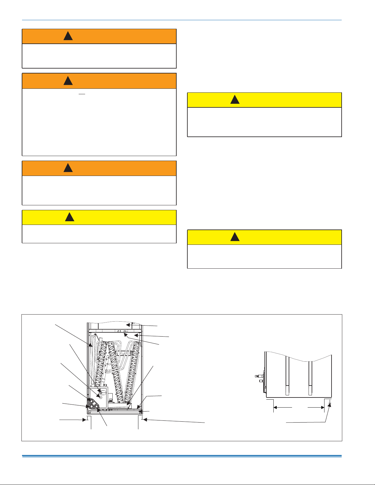
FIGURE 1: Return Air Duct Attachment & Component Location
FRONT VIEW
SECONDARY DRAIN
UPFLOW 3/4” NPT
BLOWER
COMPAR TMENT
COIL COMPART MENT
(Access panel removed)
CABINET BRACE
VERTICAL
DRAIN PAN
CABINET BRACE
FILTER DOOR
WHEN ATTACHING DUCTWORK WITH
SCREWS - KEEP SCREWS WITHIN 5/8”
OF SIDES AND BACK OF AIR HANDLER
SIDE VIEW
RETURN AIR
DUCT
A0328-001
2 Johnson Controls Ducted Systems
Page 3
INSPECTION
As soon as a coil is received, it should be checked to insure it is still
under pressure per Figure 2. The coil should be inspected for possible
damage during transit. If damage is evident, the extent of the damage
should be noted on the carrier’s freight bill. A separate request for
inspection by the carrier’s agent should be made in writing. The Local
Distributor should be consulted for more information. The drain pan
should be checked for cracks or breakage. Before installation, the unit
should be checked for screws or bolts which may have loosened in
transit. There are no internal shipping or spacer brackets that need to
be removed.
It should be verified that all accessories such as heater kits are
available. Installation of these accessories or field conversion of the unit
should be accomplished before setting the unit in place or connecting
any wiring, duct work or piping.
DEPRESS SCHRADER
CORE TO CHECK FOR
PRESSURE ONE TIME.
NOTE:
Verify that the coil is under
pressure when received.
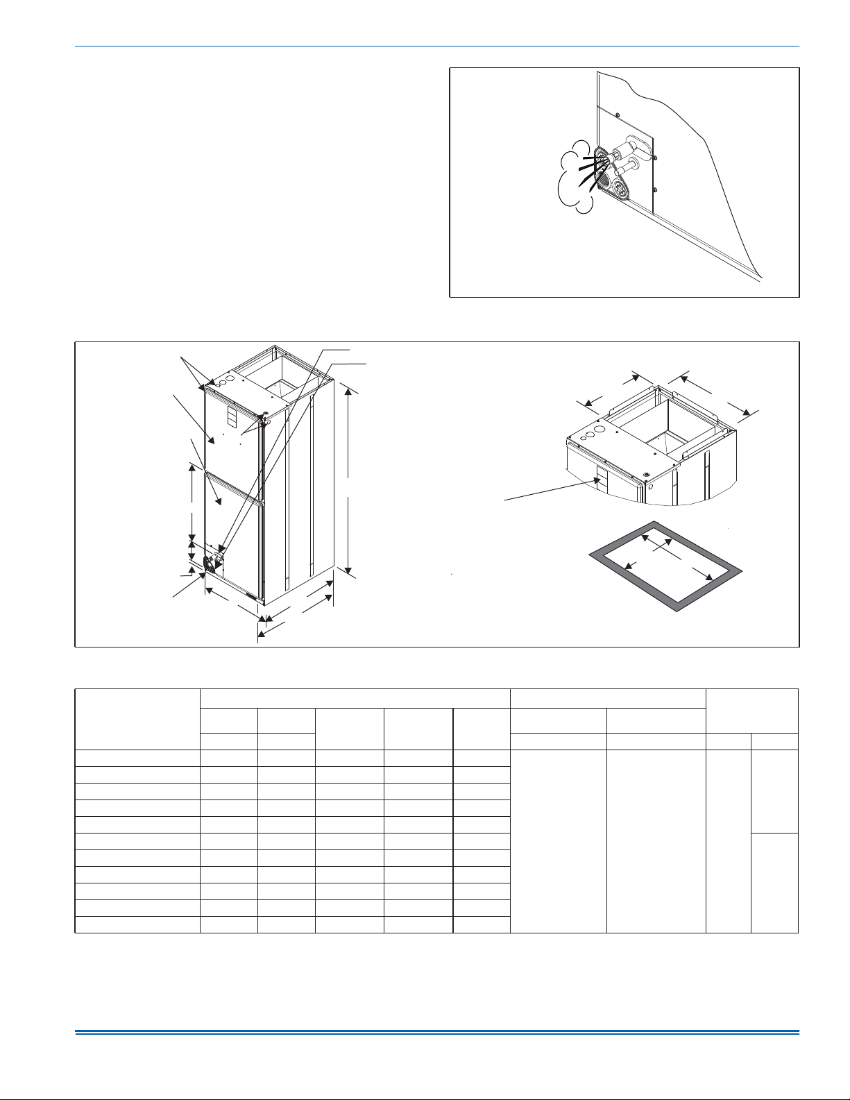
FIGURE 2: Pressure Check
5493974-UIM-B-0419
A0271-001
F
BLOWER
COMPAR TMENT
COIL
COMPAR TMENT
7-11/32
1-1/2”
FILTER ACCESS
C
G
B
20-1/2”
21-7/16”
FIGURE 3: Dimensions & Duct Connection Dimensions
TABLE 1: Dimensions
Dimensions
Models
AB
Height Width Power Control Liquid Vapor
18B 41 17-1/2 12-7/8 14-1/4 16-1/2
24B 41 17-1/2 12-7/8 14-1/4 16-1/2
30B 47-1/2 17-1/2 19-1/2 14-1/4 16-1/2
36B 47-1/2 17-1/2 19-1/2 14-1/4 16-1/2
36C 51-1/2 21 22-5/8 17-3/4 20
42C 51-1/2 21 22-5/8 17-3/4 20
48C 51-1/2 21 22-5/8 17-3/4 20
48D 55-1/2 24-1/2 26-5/8 21-1/4 23-1/2
49C 51-3/4 21 26-5/8 17-3/4 20
60C 55-3/4 21 26-7/8 17-3/4 20
60D 55-1/2 24-1/2 26-5/8 21-1/4 23-1/2
1. All dimensions are in inches.
2. Actual size (Conduit size in parenthesis).
REFRIGERANT CONNECTIONS
DRAIN CONNECTIONS
FOR UPFLOW APPLICATIONS
A
1
SERVICE
DISCONNECT
PANEL
CDE
1-23/32 (1-1/4)
12-3/16”
18-5/8”
Wiring Knockouts
D
2
FG
7/8 (1/2)
1-3/8 (1)
7/8 (1/2) 3/8
TOP OUTLET
DIMENSIONS
E
BOTTOM INLET
DIMENSIONS
A0329-001
Refrigerant
Connections
Line Size
3/4
7/8
Johnson Controls Ducted Systems 3
Page 4
5493974-UIM-B-0419
SECTION III: UNIT INSTALLATION
NOTICE
Avoid handling aluminum coil components after handling the copper
line set or other tubing without first cleaning hands.
UNIT SIZING
1. The size of the unit should be based on an acceptable heat loss or
gain calculation for the structure. The ACCA – Manual J or other
approved methods may be used. Reference Figure 3 & Table 1.
2. Only connect the air handler to a duct system which has an external
static pressure within the allowable range.
3. Airflow must be within the minimum and maximum limits approved
for electric heat, indoor coils and outdoor units.
Entering Air Temperature Limits
Wet Bulb Temp. °F Wet Bulb Temp. °F
Min. Max. Min. Max.
57 72 65 95
4. When an air handler is installed so that supply ducts carry air circulated by the air handler to areas outside the space containing the
air handler, the return air shall also be handled by duct(s) sealed to
the air handler casing and terminating in the space to be cooled/
heated.
5. Refer to the unit rating plate for the air handler model number, and
then see the dimensions page of this instruction for supply air plenum dimensions. The plenum must be installed according to the
instructions.
6. The installer must check available supply power and verify that it is
within the normal operating voltage range for the unit. The acceptable voltage range for these units is as follows:
Air Handler Voltage
208V-230V-1-60 187V-253V
1. Rated in accordance with ARI Standard 110, utilization range “A”.
Normal Operating 1 Voltage Range
3. Normal operating sound levels may be objectionable if the air handler is placed directly over some rooms such as bedrooms, study,
etc.
4. Select a location that will permit installation of condensate line to an
open drain or outdoors allowing condensate to drain away from
structure.
NOTICE
The primary and secondary drain line must be trapped to allow proper
drainage of condensate water. The secondary drain line should be
piped to a location that will give the occupant a visual warning that the
primary drain is clogged. If the secondary drain line is not used, it
must be capped.
5. When an indoor coil is installed in an attic or above a finished ceiling, an auxiliary drain pan should be provided under the air handler
as is specified by most local building codes.
6. Proper electrical supply must be available.
7. If unit is located in an area of high humidity (i.e. an unconditioned
garage or attic), nuisance sweating of casing may occur. On these
installations, unit duct connections and other openings should be
properly sealed, and a wrap of 2” fiberglass insulation with vinyl
vapor barrier should be used.
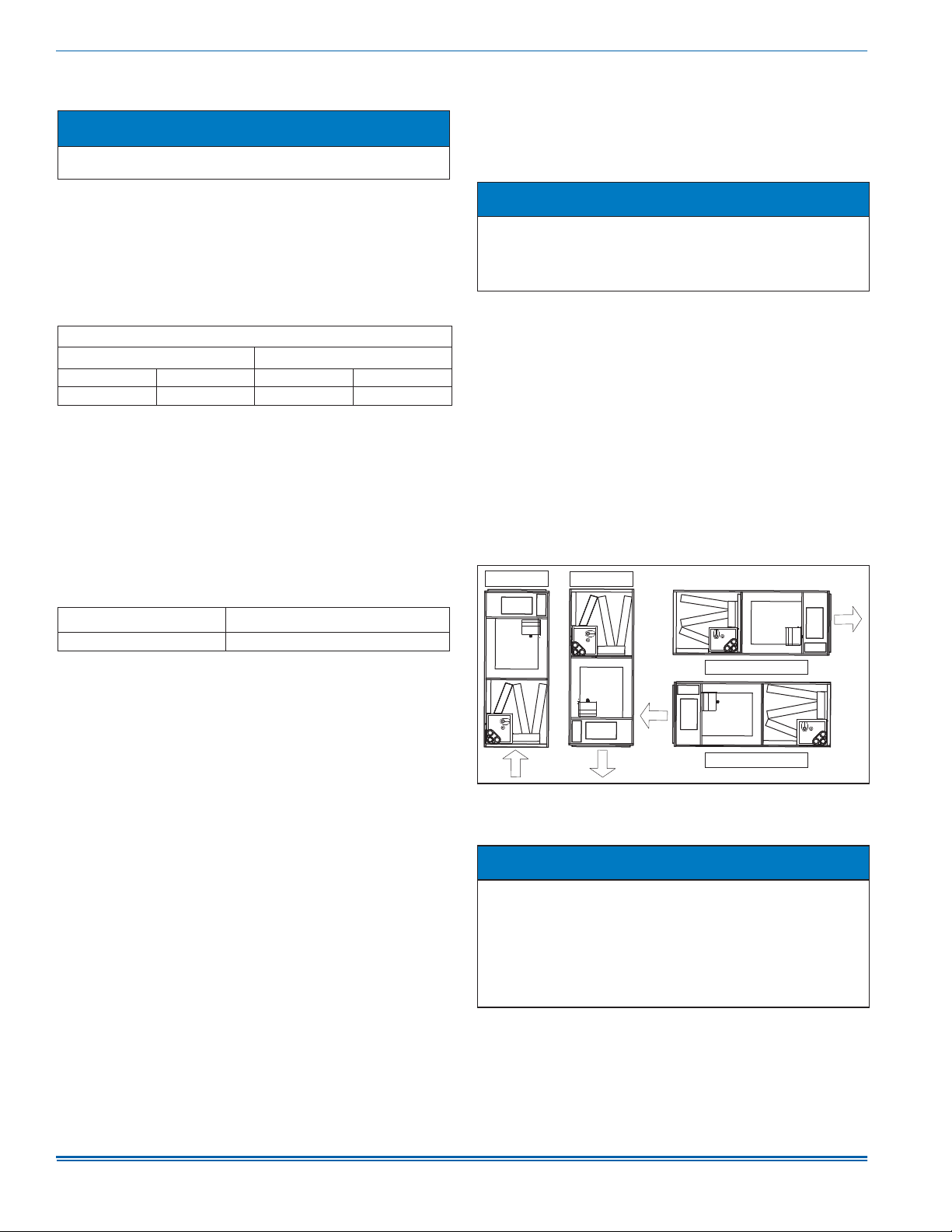
AIR HANDLER CONFIGURATION
These air handler units are supplied ready to be installed in an upflow
or horizontal left position. Refer to Figure 4. If the unit requires either
downflow or horizontal right airflow configurations, the unit must have
the coil assembly repositioned. Refer the Downflow or Horizontal Right
Conversion procedures.
UPFLOW
HEAT
DOWNFLOW
HEAT
HORIZONTAL RIGHT
CLEARANCES
Clearances must be taken into consideration, and provided for as
follows:
1. Refrigerant piping and connections - minimum 12” recommended.
2. Maintenance and servicing access - minimum 36” from front of unit
recommended for blower motor / coil replacement.
3. Condensate drain lines routed to clear filter and panel access.
4. Filter removal - minimum 36” recommended.
5. The duct work connected to this unit is designed for zero clearance
to combustible materials.
6. A combustible floor base accessory is available for downflow applications of this unit, if required by local code.
LOCATION
Location is usually predetermined. Check with owner’s or dealer’s
installation plans. If location has not been decided, consider the
following in choosing a suitable location:
1. Select a location with adequate structural support, space for service
access, and clearance for air return and supply duct connections.
2. Using hanging brackets to wall mount this single piece air handler
unit is not recommended.
T
HEAT
FIGURE 4: Typical Installation
HEA
HORIZONTAL LEFT
A0330-001
Horizontal Left Conversion
NOTICE
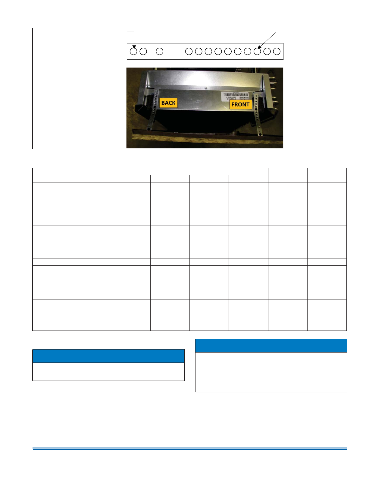
For horizontal left applications, high airflow can prevent the collected
condensate from draining properly since the direction of the airflow
opposes the direction of the draining condensate. The horizontal pan
must be angled properly in order to ensure proper drainage in high
airflow applications. Ensure that the pan is angled properly by checking that the correct hole is used on the pan straps per TABLE 2. Use
FIGURE 5 to identify the "BACK" and "FRONT" straps since, in some
cases, these settings are not the same.
4 Johnson Controls Ducted Systems
Page 5
5493974-UIM-B-0419
$77$&+0(17+2/()25
+25,=217$/'5$,13$1
FIGURE 5: Horizontal Pan Adjustment Strap Hole Reference
TABLE 2:
Horizontal Pan Strap Settings for Horizontal Left
Model
AP RFCX-P2 AE RFCX-E2 AVC CM
AP24B
AP30B
AP36B
AP60C RFCX60CP AE60C RFCX60CE AVC60C CM60C 3 4
AP36C
AP37C
AP42C
AP48C
– – AE60D RFCX60DE AVC60D CM64D 4 5
– – AE36C RFCX36CE AVC36C
–––––CM24C 6 6
AP18B RFCX18BP AE18B RFCX18BE AVC18B CM18B 7 7
AP48D
AP60D
RFCX24BP
RFCX30BP
RFCX36BP
RFCX36CP
RFCX37CP
RFCX42CP
RFCX48CP
RFCX48DP
RFCX60DP
AE24B
AE30B
AE36B
AE42C
AE48C
AE48D RFCX48DE AVC48D
RFCX24BE
RFCX30BE
RFCX36BE
RFCX42CE
RFCX48CE
AVC24B
AVC30B
AVC36B
AVC42C
AVC48C
CM24A
CM24B
CM25B
CM30A
CM30B
CM36A
CM36B
CM42C
CM48C
CM37C
CM30C
CM36C
CM30D
CM36D
CM42D
CM48D
CM60D
+2/(/2&$7,21
180%(56
$
Back Front
22
44
55
88
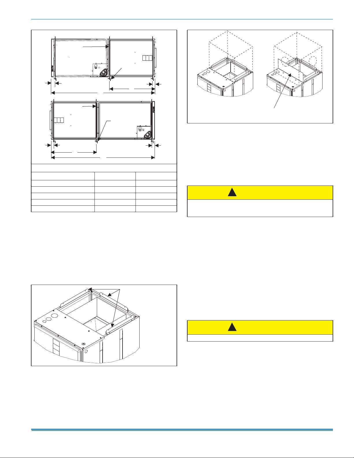
Downflow or Horizontal Right Conversion
NOTICE
NOTICE
Convert air handler to the desired orientation prior to installation.
Conversion must be made before brazing the refrigerant connections
to the coil.
1. Remove coil access panel.
2. Slide coil/drain pan assembly out of air handler.
Johnson Controls Ducted Systems 5
The center support bar for the coil/drain pan has a position identifier
embossed into the cabinet structure between the two forward fingers
of the support bar. There are four position identifiers: A, B, C, or D.
The lettered hole location can differ from unit to unit due to the cabinet width of the air handler. After removal and re-installation, the center support bar must be installed in the same lettered position that it
was originally.
3. Note the lettered position of the center support bar for the coil/drain
pan. Remove the center support bar by sliding the forward end of
the support bar to the right or left until the lower finger clears the
structure.
Page 6
5493974-UIM-B-0419
NOTICE
The position identifier for the coil slide rail is embossed into the back
corner vertical angle of the cabinet structure. There are four position
identifiers: 1, 2, 3, or 4. The numbered attachment location can differ
from unit to unit due to the cabinet height of the air handler. After
removal and re-installation, the coil slide rail must be installed in the
same numbered position that it was originally.
4. Note the numbered position of the coil slide rail located at the upper
right hand side of the indoor coil compartment. Remove slide rail
from air handler cabinet by removing front screw and lowering
bracket down to disengage hook on back of slide rail.
5. Turn air handler cabinet upside down (downflow position).
6. Install coil slide rail by hooking the hook end into holes at the numbered position the slide rail was originally in right rear corner post,
and secure rail into right front edge of cabinet with screw in the predrilled hole.
NOTICE
The rear of the center support bar are longer than the fingers on the
forward end of the support bar.
7. Install center support bar for the coil/drain pan onto the lettered
position that it was originally mounted.
NOTICE
When installing a coil condensate deflector, make sure that each
notch in the coil condensate deflector slides around the anchor screw
with the bottom of the notch fully set against the screw.
Ensure that the coil condensate deflector is installed with the flange
bending away from the coil delta plate.
8. For horizontal right applications, install front and back coil condensate deflectors (condensate deflectors shipped as loose parts with
the unit). Locate 4 screws securing coil delta plates to coil drain
pan. Loosen the screws. Slide each coil condensate deflector
between the drain pan and the coil delta plate. Tighten screws to
securely anchor coil condensate deflectors. Refer to Figure 6.
NOTICE
Some models contain condensate deflectors that are not symmetrical
and must be installed in the correct orientation. If this air handling unit
is a **60C model, refer to the horizontal right conversion section on
the next page.
9. Slide the coil back into the cabinet. Be sure to engage the side coil
slide into the slide rail on the air handler cabinet.
10. Install coil access panel. Conversion is now complete.
COIL
DELTA PLATE
CONDENSATE
BLOW OFF WING
DEFLECTOR
SCREWS
(2 per deflector)
(2 per blow off wing)
INSTALL COIL CONDENSATE
INSTALL COIL BLOW
OFF WING ON FRONT
DEFLECTOR ON FRONT
AND BACK OF COIL
AND BACK OF COIL
DRAIN PAN
FIGURE 6: Coil Condensate Deflector Installation
Handling Coil Assemblies when Removed from Casing
When the coil assembly is removed from its casing, it must be handled
in such a manner that does not compromise the foam gasket that seals
the attachment point of the horizontal drain pan and primary drain pan.
DO NOT position the coil so that the coil weight rests on the horizontal
drain pan. By doing so, the horizontal drain pan straps could deform or
become damaged which will not allow the pan to be positioned/angled
correctly when the unit is horizontally installed, and if the foam gasket
that seals the attachment point becomes compromised by the movement of the horizontal drain pan, condensate may leak at this point and
cause damage to the unit/property.
Positioning the Unit in Horizontal Applications
Set unit so that it is sloped 1/4” towards the drain plug.
A0417-001
A0417-002
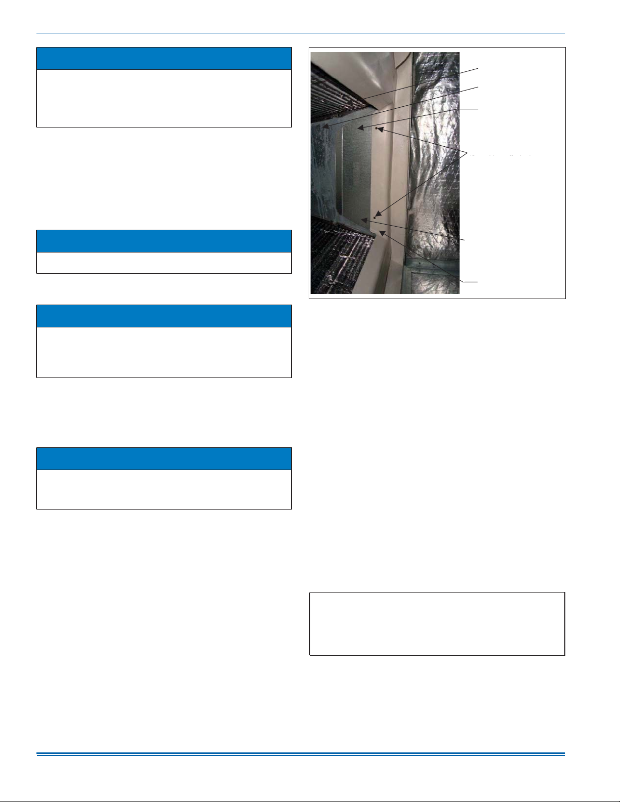
AVC60C Downflow or Horizontal Right
The AVC60C model contains a unique coil assembly in that additional
pieces are required to be installed in horizontal right and downflow
applications to reduce the potential for condensate blow-off. The large
cooling capacity and high volumetric airflow (1800 CFM and above)
required for these coils put them more at risk of condensate blow-off.
The installation of additional shields should mitigate condensate management issues while allowing the coil to perform adequately for proper
cooling/heating.
When installing any of the shield provisions, it is advised to position the
coil such that the primary drain pan opening can be easily accessed to
attach the shields. See Figure 7.
IMPORTANT: DO NOT position the loose coil so that it rests on the
horizontal drain pan. The weight of the coil will deform the horizontal
pan straps, and the movement of the horizontal pan could potentially
compromise the foam gasket that seals the horizontal drain pan to the
primary drain pan. This could lead to water leaking at this attachment
point and damaging the insulation/cabinet/property.
6 Johnson Controls Ducted Systems
Page 7
5493974-UIM-B-0419
A1076-001
FIGURE 7: Recommended Position of Coil to Install Downflow/
Horizontal Right Condensate Components
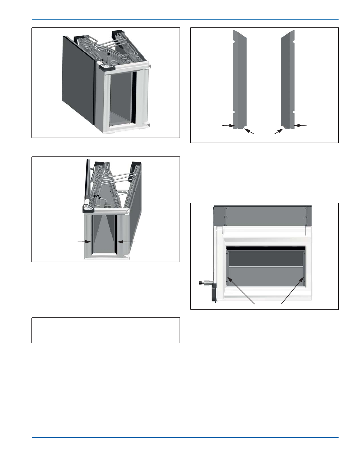
Condensate Shield
- Downflow Only
Condensate Shield
(Factory Installed)
(Field Installed)
A1074-001
FIGURE 8: Installation of Downflow Condensate Diverter Shields
AVC60C Horizontal Right
1. Attach the additional condensate deflectors that were included in
the loose parts kit to the coil assembly by loosening the screws that
secure the front and rear delta plates to the primary drain pan. DO
NOT remove the screws completely. Loosen them enough so that
you can insert the deflectors between the drain pan and the delta
plate.
IMPORTANT: FOR 60C (21.0”) COIL ASSEMBLIES: While the
shields may appear similar, they are actually different in that there is a
front and rear shield. Due to their asymmetry, these shields will not fit
correctly if they are oriented incorrectly. See Figure 9 for details.
Front Deflector
(Orient Towards Bottom Coil Slab)
Drip Leg
Rear Deflector
A1075-001
FIGURE 9: 60C Horizontal Right Condensate Deflectors
2. Insert the deflectors between the primary drain pan and the delta
plates. Make sure that the slots in the deflectors nest firmly against
the loosened screws between the primary drain pan and delta
plates.
3. Tighten the screws that secure the delta plates to the primary drain
pan. The interactive fit of the delta plate, primary drain pan, and
screws will hold the shields firmly in place during operation. Figure
10 shows the final assembly.
Condensate Deectors
A1077-001
FIGURE 10: 60C Horizontal Right Coil Condensate Final Assembly
Johnson Controls Ducted Systems 7
Page 8
5493974-UIM-B-0419
Upflow or Downflow Applications (All Models)
NOTICE
For maximum performance, if an air handling unit is being installed in
Upflow or Downflow orientation, it is recommended that the horizontal
drain be removed from the assembly. This can be achieved by removing the horizontal drain pan support straps, cutting the foam gasket
that seals the attachment point of the horizontal drain pan and primary drain pan, and removing the entire horizontal drain pan assembly.
AVC60C Downflow Conversion
1. Rotate equipment cabinet so that the bottom of the primary (plastic)
drain pan can be accessed.
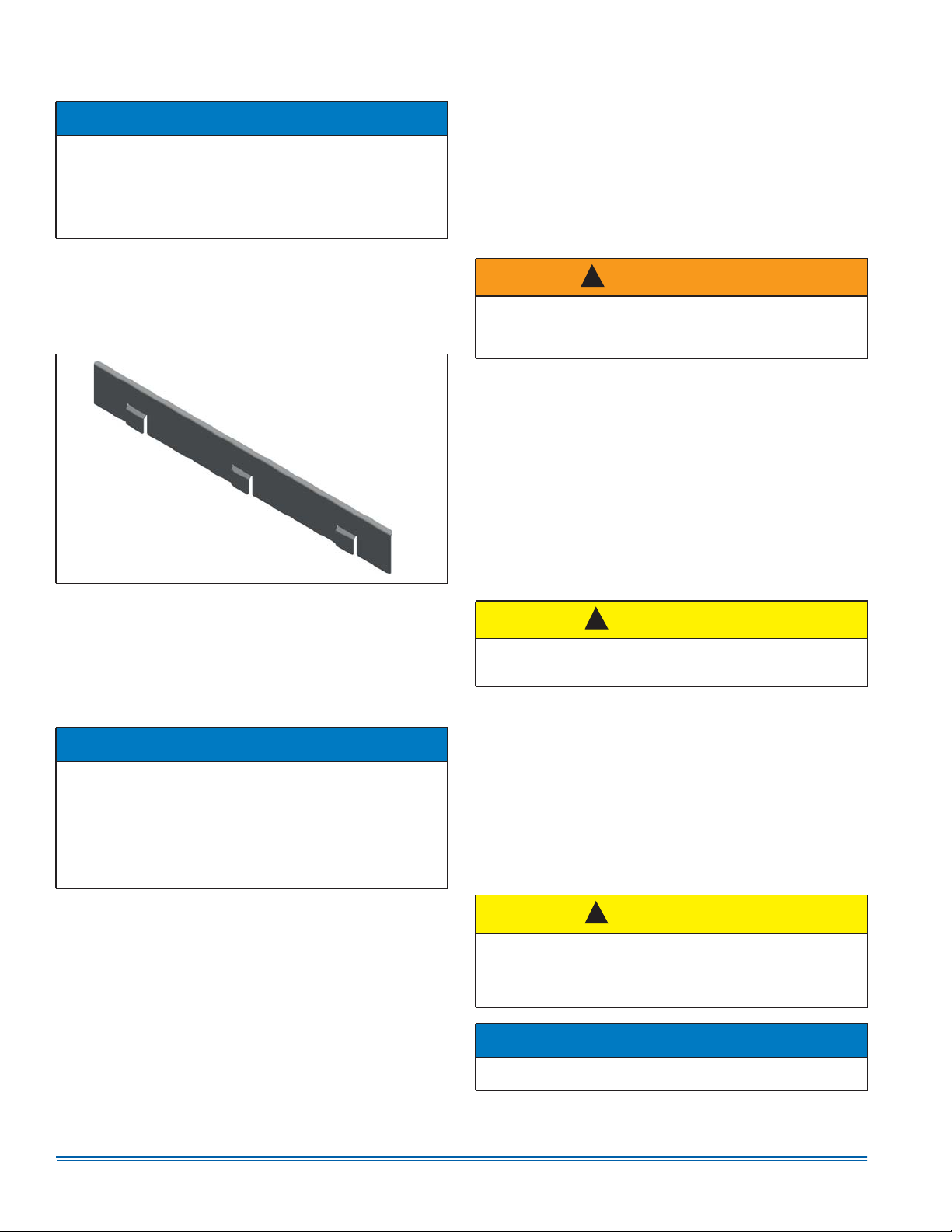
2. Locate the downflow condensate shield (as shown in Figure 11)
and foam gasket strip shipped in the loose parts kit included with
the coil.
A1073-001
FIGURE 11: Condensate Shield
3. Install the condensate shield to the primary drain pan (as shown in
Figure 8). There should be an identical condensate shield that was
factory installed on the opposite side of the primary drain pan.
4. Apply the foam gasket strip to the condensate shield evenly so that
it covers the condensate shield and primary drain pan.
Horizontal Left Applications (All Models)
NOTICE
For horizontal left applications, high airflow can prevent the collected
condensate from draining properly since the direction of the airflow
opposes the direction of the draining condensate. The horizontal pan
must be angled properly in order to ensure proper drainage in high
airflow applications. Ensure that the pan is angled properly by checking that the correct hole is used on the pan straps per TABLE 2. Use
FIGURE 5 to identify the FRONT and REAR straps since, in some
cases, these settings are not the same.
The vast majority of problems encountered with heating and cooling
systems can be linked to improperly designed or installed duct systems.
It is therefore highly important to the success of an installation that the
duct system be properly designed and installed.
When installing a central air return grille in or near the living space, it is
advisable to design the duct work so that the grille is not in direct line
with the opening in the unit. One or two elbows and acoustical duct liner
assures a quieter system. Operation where return air duct is short or
where sound may be a problem, acoustical duct liner should be used
inside the duct. Use flexible duct connectors to minimize the
transmission of vibration/noise into the conditioned space.
!
WARNING
Do not bring in return air from a location which could introduce hazardous substances into the airflow.
Use 1/2” screws to connect duct work to cabinet. If pilot holes are
drilled, drill only through field duct and unit flange.
Insulation of duct work is a must where it runs through an unheated
space during the heating season or through an uncooled space during
the cooling season. The use of a vapor barrier is recommended to
prevent absorption of moisture from the surrounding air into the
insulation.
The supply air duct should be properly sized by use of a transition to
match unit opening. All ducts should be suspended using flexible
hangers and never fastened directly to the structure.
Duct work should be fabricated and installed in accordance with local
and/or national codes. This includes the standards of the National Fire
Protection Association for Installation of Air-Conditioning and
Ventilating Systems, NFPA No. 90B. Duct systems should be designed
in accordance with the Air Conditioning Contractors of America (ACCA)
– Manual D.
!
CAUTION
This unit is not designed for non-ducted (freeblow) applications. Do
not operate without duct work attached to unit.
Equipment should never be operated without filters.
Use flexible duct collars to minimize the transmission of vibration/noise
into the conditioned space. If electric heat is used, non-flammable
material must be used.
All ducts should be suspended using flexible hangers and never
fastened directly to the structure.
HORIZONTAL SUSPENSION
These air handlers may be suspended in horizontal applications. It is
recommended to use angle steel support brackets with minimum 3/8”
threaded rods, supporting the unit from the bottom. Attach the threaded
rods at the locations shown in the Figure 12, leaving enough clearance
between door and rod so that doors maybe easily removed for service.
Air handling units are supplied ready to be installed in a horizontal left
position. A horizontal drain pan is factory installed. If horizontal right
application, refer to the horizontal right conversion before proceeding.
See sections on “Refrigerant Line Connections” and “Condensate Drain
Connections” for further installation instruction.
SECTION IV: DUCT WORK AND
DO NOT lift air handler by the cabinet brace. The cabinet brace is
held in place by the coil channel. The cabinet brace could become
disengaged from the cabinet causing the air handler to fall, potentially
causing injury or damaging property. See Figure 1 for location of cabinet braces.
!
CAUTION
CONNECTIONS
Air supply and return may be handled in one of several ways best
suited to the installation. Upflow, horizontal or downflow applications
may be used.
When assembling the support structure, make sure to size to provide
clearance for access door removal.
8 Johnson Controls Ducted Systems
NOTICE
Page 9
SUSPENSION SUPPORT LOCATIONS FOR HORIZONTAL APPLICATIONS
MIN. 3/8”
THREADED ROD
MIN. 1-1/2” x 1-1/2”
Angle Recommended
length 26” minimum
with 2” clearance
on both sides
of Air Handler
5493974-UIM-B-0419
2”
MIN. 3/8”
THREADED ROD
1-1/2”
X
H
MIN. 1-1/2” x 1-1/2”
Angle Recommended
length 26” minimum
with 2” clearance on
both sides of
Air Handler
H
1-1/2”
X
1-1/2”
A0331-001
Dimension in Inches
Air Handler Cabinet Size X H
17-1/2 Width-Short H 21 41
17-1/2 Width-Long H 21 47-1/2
21 Width-Short H 21-1/2 51-1/2
21 Width-Long H 21-1/2 55-3/4
24-1/2 Width 21-1/2 55-1/2
FIGURE 12: Horizontal Suspension
DUCT FLANGES
Three duct flanges are provided to assist in positioning and attaching
duct work to the air handler. These flanges are included in the unit parts
bag. With the screws from the parts bag, install one of the duct flanges.
Duct flanges have holes on both legs with one leg longer than the other.
The longer leg can be used to mate against the air handler so that
different thicknesses of duct board can be made flush with the outer
surface of the air handler. Repeat the procedure for the other two
flanges. Refer to Figure 13. If the flanges are not used, they may be
discarded.
DUCT FLANGES
(Shipped in bag with unit)
RECOMMENDED
TRANSITION
SUGGESTED LOCATION
OF BLOCK OFF PLATE
A0332-001
FIGURE 14: Duct Work Transition
UNIT CONNECTIONS
There are several ways to handle the supply and return air duct
connections. The location and sizing of the connections depends on the
situation and the method best suited to the installation. Upflow,
horizontal or downflow applications may be used.
The supply air duct should be properly sized by use of a transition to
match unit opening. Refer to Table 1 for air handler unit inlet and outlet
dimensions.
!
CAUTION
Use 1/2” screws to connect duct work to unit. Longer screws will
pierce the drain pan and cause leakage. If pilot holes are drilled, drill
only though field duct and unit bottom duct flange.
Duct work that is not designed to match the supply air opening can
cause turbulence inside the plenum. This turbulence can change the air
flow patterns across the electric heater limit switches. If the factory
suggested transition cannot be fabricated, it is recommended that a
block off plate (approximately 8" high and running the full width of the
plenum) be attached to the supply opening. Refer to Figure 14 as a
visual aid. The use of this block off plate will enable better air circulation
across the limit switches.
AIR FILTERS
Return air filters are required and must be field supplied. Filtration can
be accomplished external to the unit or the integral filter rack may be
used. A 1" filter access rack has been built into the unit. Remove filter
access cover shown. Install proper size filter. Standard 1" size
permanent or throw away filter may be used, or permanent washable
filters are available using model numbers: 1PF0601, 602 or 603. See
Table 7 for filter size.
.
!
CAUTION
Equipment should never be operated without filters.
SECTION V: COIL METERING DEVICES
A0445-001
FIGURE 13: Duct Attachment
Johnson Controls Ducted Systems 9
A piston or a TXV is to be installed in the field. There is an installation
manual that comes with the TXV kit. It is recommended to install the
piston or TXV kit prior to installation of coil and brazing of line set. Until
brazing is completed and cooled, the TXV sensing bulb must not be
installed.
The outdoor technical guide for outdoor units should be consulted for
required piston or TXV on the indoor coil. The piston and the Schrader
core are supplied with the outdoor unit. When the piston is used instead
of the TXV, the Schrader core is installed in the suction line equalizer
connection port and is capped with the supplied plastic cap. The
Schrader core must not be installed if the TXV is installed, because the
TXV equalizer line attaches to the equalizer connection port.
Page 10

5493974-UIM-B-0419
$
!
CAUTION
COIL UNDER PRESSURE.
Verify that pressure has been released by depressing schrader valve
core.
The coil requires a metering device to be added.
See outdoor unit documentation for correct TXV or piston to be used.
NOTICE
To prevent moisture and contaminates from entering the system, the
coil should not be open to atmosphere for extended periods of time. If
the coil cannot be brazed into the refrigeration system during a routine installation period, the ends should be temporarily closed or
plugged. For a short term delay, use masking tape over the ends of
the copper tubing to close the tube from the air. For a longer term
delay, use plugs or caps. There is no need to purge the coil if this procedure is followed.
PISTON INSTALLATION
!
WARNING
Failure to install Schrader Valve Core in the vapor line equalizer connection port for piston applications could result in total refrigerant loss
of the system!
Install Schrader Valve Core and
1. After holding charge is completely discharged, remove black plastic
cap from equalizer connection port on the vertical part of the vapor
line.
2. Distributor position must be adjusted to allow the preformed liquid
line assembly to properly line up with the hole in the tubing access
panel. Raise the distributor body approximately 2” toward the top of
the coil or what would be the top of the coil if coil was in the upflow
position. See Figure 15. Adjust as necessary.
3. Install Schrader valve core supplied with the outdoor unit into the
equalizer fitting connection port using a valve core tool.
4. Loosen and remove the liquid line connection nut and the sealing
disc from the distributor assembly. Note that the fitting has right
hand threads.
5. Slide the nut over the liquid line to be installed, and discard the seal
disc.
6. Install required size piston into the distributor. Refer to supplied
Tabular Data Sheet for specific piston size and indoor coil match
up. See Figure 16.
7. Verify that the Teflon washer is still in place in the distributor open-
ing. See Figure 16.
Piston as follows:
LIQUID LINE SWIVEL COUPLING
(This fitting is a right-handed thread.
Turn counter-clockwise to remove.)
PISTON
TEFLON WASHER
DISTRIBUTOR
A0305-001
FIGURE 16: Piston Installation
!
CAUTION
Do not overtorque. Do not use slip joint pliers. This will distort the aluminum distributor and the brass fitting (potentially causing leaks).
8. After piston is installed, install the liquid line to the top of the piston/
distributor assembly. Hand tighten, and turn an additional 1/4 turn
to seal. Do not over tighten fittings.
9. Replace black plastic cap on unused equalizer fitting connection
port.
10. After line set is installed, leak test the system.
THERMOSTATIC EXPANSION VALVE (TXV) INSTALLATION
!
CAUTION
Outdoor unit model numbers ending with an “H” have a factory
installed hard start kit which is required when a TXV is installed. Outdoor unit model numbers with no “H” ending do not require a hard
start kit unless local regulations dictate it.
The following are basic steps for installation. For detailed instructions,
refer to the Installation Instructions accompanying the TXV kit. Install
TXV kit as follows:
IMPORTANT: Refer to the Technical Guide for the unit to determine
the proper TXV kit to be used on this product.
1. Relieve the holding charge by depressing Schrader core on the
suction manifold stub out.
2. After holding charge is completely discharged, loosen and remove
the Schrader core.
3. Place a backup wrench on distributor, loosen and remove brass
distributor nut. Retain brass nut for use on liquid line. Keep Teflon
washer in place and discard clear disk.
4. Install the thermal expansion valve to the distributor assembly with
supplied fittings. Ensure Teflon washer is seated in distributor.
Hand tighten and turn an additional 1/4 turn to seal.
tighten fittings. See Figure 17.
Do not over-
!
CAUTION
Do not over-torque. Do not use slip joint pliers. This will distort the
aluminum distributor and the brass fitting (potentially causing leaks).
5. Slide the nut removed in step 3 over the supplied liquid line. Place
supplied Teflon washer from TXV kit in place on TXV, and install liquid line to the top of the thermal expansion valve. Adjust assembly
FIGURE 15: Recommended Distributor Adjustment
so liquid line aligns with hole in access panel. See Figure 18. Hand
tighten the liquid line, and apply an additional 1/4 turn to seal.
10 Johnson Controls Ducted Systems
Page 11

5493974-UIM-B-0419
LIQUID LINE / TXV COUPLING
TEFLON WASHER
TXV
TXV / DISTRIBUTOR COUPLING
TEFLON WASHER
DISTRIBUTOR
A0281-002
FIGURE 17: TXV Installation
!
WARNING
Schrader valve core MUST NOT be installed with TXV installation.
Poor system performance or system failure could result.
6. Install the TXV equalizer line onto the vapor line by hand tightening
the 1/4” SAE coupling nut to the equalizer fitting, and apply an additional 1/3 turn to seal. See Figure 18.
!
CAUTION
In all cases, mount the TXV temperature sensing bulb after vapor line
is brazed and sufficiently cooled.
Failure to use suction line split grommet may result in TXV failure.
9. After line set is installed, leak test the system.
Bulb at
10 o’clock
position.
CLAMP
VAPOR
LINE
TXV SENSING BULB
(Pass through split hole
in grommet.)
SCREW
NUT
CLAMP
Bulb at
2 o’clock
NUT
SCREW
DETAIL A
position.
VAPOR LINE
OF LINE SET
FIGURE 19: Proper Bulb Location
CLAMP
VAPOR LINE
OF LINE SET
TXV BULB
(Cover completely
with insulation.)
TAIL END UP
TXV
TEMPERATURE
BULB
A
A0269-002
7. Pass the temperature sensing bulb tube for the TXV through the
tube opening in the split grommet of the access panel.
8. Install the TXV bulb to the vapor line near the cabinet, using the
bulb clamp(s) furnished with the TXV assembly. Ensure the bulb is
making maximum contact. See Figures 18 & 19, and accomplish
the following:
a. If possible, install the temperature bulb on a horizontal run of
the vapor line. Ensure that the bulb is installed at a 10 o’clock
or 2 o’clock position.
b. If bulb installation is made on a vertical run, ensure that the
bulb is a minimum of 8 inches (20.3 cm) away from elbow
coming out of the coil. Position the bulb with the tail of the
bulb at the top, so that the bulb acts as a reservoir. See Figure 20.
c. Insulate the bulb using thermal insulation provided to protect
it from the effect of the surrounding ambient temperature.
Cover completely to insulate.
TXV BULB
(Wrap with
insulation.)
DISTRIBUTOR
BODY
VAPOR LINE
LIQUID LINE
TVX
EQUALIZER
LINE
THERMAL EXPANSION
VALVE (TXV)
A0279-002
FIGURE 18: TXV Bulb and Equalizer line Installations
NOTE:
Ensure bulb is on opposite
side of tubing bend plane.
8” (20.3 cm)
A0378-002
FIGURE 20: Vertical Temperature Bulb Orientation
SECTION VI: REFRIGERANT LINE CONNECTION
!
CAUTION
Coil is under inert gas pressure. Relieve pressure from coil by
depressing Schrader core at end of suction manifold stub out.
!
CAUTION
Dry nitrogen should always be supplied through the tubing while it is
being brazed, because the temperature required is high enough to
cause oxidation of the copper unless an inert atmosphere is provided.
The flow of dry nitrogen should continue until the joint has cooled.
Always use a pressure regulator and safety valve to insure that only
low pressure dry nitrogen is introduced into the tubing. Only a small
flow is necessary to displace air and prevent oxidation.
Johnson Controls Ducted Systems 11
Page 12

5493974-UIM-B-0419
$
*5200(7
)RU9DSRU/LQH
NOTICE
Avoid handling aluminum coil components after handling the copper
line set or other tubing without first cleaning hands.
Connect lines as follows:
NOTICE
Route the refrigerant lines to the coil in a manner that will not obstruct
service access to the coil, air handling system, furnace flue or filter.
1. Suction and liquid line connections are made outside the cabinet.
Leave the tubing connection panel attached to the cabinet. Coil
access panel should be removed for brazing. The lines are
expanded to receive the field line set tubes for most outdoor unit
matches.
2. Remove grommets where tubes exit the cabinet to prevent burning
them during brazing. In some units, the vapor line grommet may be
shipped as a loose part with the unit. Refer to Figure 21.
3. Cut the end of the suction tube using a tube cutter. Place the tube
cutter as close as possible to the end of the tube to allow as much
depth as possible for the connection and brazing of the suction line.
To ensure suction line fits into connection, deburr the stub out
(including inner pressure protrusion from cutting).
4. If coil does not have a factory installed TXV, install the required size
piston or TXV kit. See coil metering devices section for detailed
instructions.
5. If the coil does have a factory installed TXV, remove the liquid line
copper cap which is soft soldered onto the outside of the 3/8” stub
protruding from front of the coil cabinet tubing panel as follows:
a. Screw a sheet metal screw into the center of the cap.
b. Apply a small amount of heat to the cap while pulling on the
screw using slip joint pliers.
6. Insert liquid and suction lines into the coil connections at the coil
cabinet tubing panel.
7. Wrap a water soaked rag around the coil connection tubes inside
the cabinet to avoid transferring excess heat to the coil or TXV.
8. Purge refrigerant lines with dry nitrogen.
FIGURE 21: Vapor Line Grommet
SECTION VII: CONDENSATE DRAIN CONNECTIONS
All drain lines should be trapped a minimum of three inches, should be
pitched away from unit drain pan and should be no smaller than the coil
drain connection.
!
CAUTION
DO NOT use TeflonTM tape, pipe thread compound, or other
sealants. The use of a sealant may cause damage and premature
failure of the drain pan.
Threaded drain connection should be hand-tightened, plus no more
than 1 turn.
Avoid Double Trapping of a single drain line.
Route the drain line so that it does not interfere with accessibility to the
coil, air handling system or filter and will not be exposed to freezing
temperatures. See Figures 29 & 30 for drain connection locations.
NOTICE
All indoor coil connections are copper-to-copper and should be
brazed with a phosphorous-copper alloy material such as Silfos-5 or
equivalent. DO NOT use soft solder.
9. Braze the suction and liquid lines, and allow the joints to cool.
10. Route the TXV sensing bulb through suction line opening.
11. Secure sensing bulb and equalizer line capillary tubes with nylon
cable ties to prevent leaks from tubes rubbing.
12. If piston is used, install Schrader core into suction header, and reinstall cap.
13. Re-attach the grommets to the lines carefully to prevent air leakage. In some units, the vapor line grommet may be shipped as a
loose part with the unit. Refer to Figure 21.
14. Attach the coil access panel to the cabinet.
15. Refer to Outdoor unit Installation Manual, and accomplish evacuation, leak check and charging instructions. Check all field brazed
joints and metering device connections.
16. Ensure lines are sound isolated by using appropriate hangers or
strapping.
!
CAUTION
When the unit is installed in an attic or above a finished ceiling, an
auxiliary drain pan should be provided under the coil as specified by
most local building codes. When this exterior secondary drain pan is
used that drain should be piped to a location that will give the occupant a visual warning that the primary drain is clogged.
If the coil is provided with a secondary drain it should be piped to a
location that will give the occupant a visual warning that the primary
drain is clogged. If a secondary drain is not used it must be plugged.
Instruct the owner that the indoor coil drain pan should be inspected
and cleaned regularly to prevent odors and assure proper drainage. If a
secondary drain is not used it must be plugged. See Figures 29 & 30.
Coils should be installed level or pitched slightly toward the drain end.
Suggested pitch should not exceed 1/4 inch per foot of coil.
The drain pan connections are designed to ASTM Standard D 2466
Schedule 40. Use 3/4” PVC or steel threaded pipe. Since the drains are
not subject to any pressure it is not necessary to use Schedule 40 pipe
for drain lines.
12 Johnson Controls Ducted Systems
Page 13

5493974-UIM-B-0419
SECTION VIII: ELECTRIC HEATER INSTALLATION
If the air handler requires electric heat, install the electric heat kit
according to the installation instructions included with the kit. After
installing the kit, mark the air handler nameplate to designate the heater
kit that was installed. If no heater is installed, mark the name plate
appropriately to indicate that no heat kit is installed.
Use only 6HK Revision C or later heater kits, as listed on air handler
name plate and in these instructions. Use data from Tables 9 & 16 for
information on required minimum motor speed tap to be used for
heating operation and maximum over-current protection device
required as listed for combination of air handler and heater kit.
For Upflow, Downflow and Horizontal left-hand applications, the kits can
be installed without modification.
Field modification is required for Horizontal right-hand airflow application only. Follow instructions with heater for modification.
NOTICE
In some horizontal applications, the service disconnects on the electric heat kits must be rotated 180° so the up position of the disconnect is the ON position. This service disconnect orientation change is
required by UL1995, Article 26.19 (in reference to all circuit breakers).
3+$6((/(&75,&+($7237,216
6,1*/(6285&(32:(5
*1'
12(/(&75,&+($7
*1'
32:(5
6833/<
&20321(17&2'(6
*1'*5281'/8*
6'6(59,&(',6&211(&7
&.7&,5&8,7
&1:,5(&211(&725187
),(/'32:(5:,5,1*
9
&1
&1
32:(5
6833/<
/
/
7(50,1$/%/2&.25
6(59,&(',6&211(&7
6,1*/(6285&(32:(5
32:(5
6833/<
FIGURE 22: Line Power Connections
SECTION X: LOW VOLTAGE CONTROL CONNECTIONS
The 24 volt power supply is provided by an internally wired low voltage
transformer which is standard on all models, However, if the unit is connected to a 208 volt power supply, the low voltage transformer must be
rewired to the 208 volt tap. See the unit wiring label.
Remove desired knockout and pierce foil faced insulation to allow wiring to pass through. Use as small of a hole as possible to minimize air
leakage.
Install a 7/8” plastic bushing in the selected hole and keep low voltage
wiring as short as possible.
To further minimize air leakage, seal the wiring entry point at the outside of the unit.
32:(5
6833/<
3+$6((/(&75,&+($732:(5237,216
*1'
/
/
/
7(50,1$/%/2&.25
6(59,&(',6&211(&7
SECTION IX: LINE POWER CONNECTIONS
Power may be brought into the unit through the supply air end of the
unit (top left when unit is vertical) or the left side panel. Use the hole
appropriate to the unit’s orientation in each installation to bring conduit
from the disconnect. The power lead conduit should be terminated at
the electrical control box. To determine proper wire sizing, refer to
Tables 7 - 10 and the latest edition of the National Electric Code or in
Canada the Canadian electrical Code and local codes to determine
correct wire sizing. To minimize air leakage, seal the wiring entry point
at the outside of the unit.
All electrical connections to air handlers must be made with copper
conductors. Direct connection of aluminum wiring to air handlers is
not approved.
If aluminum conductors are present, all applicable local and national
codes must be followed when converting from aluminum to copper
conductors prior to connection to the air handler.
If wire other than uncoated (non-plated), 75° C ambient, copper wire is
used, consult applicable tables of the National Electric Code (ANSI/
NFPA 70). The chosen conductor and connections all must meet or
exceed the amperage rating of the overcurrent protector (service
disconnect or fuse) in the circuit.
Additionally, existing aluminum wire within the structure must be sized
correctly for the application according to National Electric Code and
local codes. Caution must be used when sizing aluminum rather than
copper conductors, as aluminum conductors are rated for less current
than copper conductors of the same size.
08/7,6285&(32:(5
:,7+-803(5%$5
/
/
-803(5%$5
&,5&8,7621N:N:
&,5&8,7621N:
*1'
6'
6'
6'
32:(5
6833/<
32:(5
6833/<
08/7,6285&(32:(5
&.7
&.7
08/7,6285&(32:(5
&.7
&.7
&.7
&,5&8,7621N:N:
&,5&8,7621N:
*1'
/
/
/
/
/
/
6'
6'
/
/
/
/
/
/
The field wiring is to be connected with wire connectors to the wires
provided. Refer to Figures 24 & 25.
NOTICE
All wiring must comply with local and national electrical code requirements. Read and heed all unit caution labels.
NOTICE
It is possible to vary the amount of electric heat turned on during the
defrost cycle of a heat pump. Standard wiring will only bring on the
first stage of electric heat during defrost. See Table 5 for additional
information on heat during defrost cycle.
*1'
6'
6'
6'
$
Johnson Controls Ducted Systems 13
Page 14

5493974-UIM-B-0419
HUMIDIFIER
OUTPUT
ELECTRONIC
AIR CLEANER
EAC
CFM
INDICATOR
LEAVING AIR TEMP
SENSOR TERMINALS
SERVICE
TOOL
PORT
COMM
PORT
FUSE
FLOAT SWITCH
INPUT
FIGURE 23: Control Board
Humidity Switch Input
The air handler control is designed to work with a humidity control that
closes when the humidity is below the set-point. The control is open
when the humidity is above the set-point. This humidity control may be
referred to as a humidistat or a dehumidistat.
The humidity switch controls de-humidification operation of the control
during cooling operation. The humidity switch should be connected to
HUM wire of the control. See Figures 23 & 24.
STATUS
INDICATOR
BLOWER
SPEED
JUMPERS
HUMIDISTAT
JUMPER
AC/HP JUMPER
MODEL
ID PLUG
A0405-001
NOTICE
All wiring must comply with local and national electrical code requirements. Read and heed all unit caution labels.
It is possible to vary the amount of electric heat turned on during the
defrost cycle of a heat pump. Standard wiring will only bring on the
first stage of electric heat during defrost. See Heat Output and Limit
Connections and Table 5 for additional information on heat during
defrost cycle.
TABLE 3:
Low Voltage Connections
Wire Colors Signals Comment
R Red 24 VAC power (fused)
G Green Continuous Fan operation Fan Speed, 63% of high cool speed.
Y/Y2 Yellow Second or full stage compressor operation
Y1 Yellow & Black First stage compressor operation Not used with outdoor units having one stage compressors.
W2 Brown Second stage heat operation
W1 White First stage heat operation
O Orange Reversing valve operation
EAC Field Supplied Wiring Electric Air Cleaner
X/L Field Supplied Wiring
HUM Purple Humidity switch input
C (COM) Blue 24 VAC common
Connection point for heat pump fault indicator
Located on P2 connector. There is 24VAC output during indoor blower
operation to energize a pilot duty relay for an electronic air cleaner.
This terminal is a connection point only and does not affect air handler control operation.
The field wiring is to be connected at the pigtails supplied with the control board harness.
14 Johnson Controls Ducted Systems
Page 15

FIGURE 24: Cooling Models with and without Electric Heat Wiring
$LU+DQGOHU&RQWURO:LULQJ
7\SLFDO$&&RROLQJRQO\$SSOLFDWLRQV
7+(50267$7
321$,5
+$1'/(5
%2$5'
67$*(
$,5&21',7,21,1*
55
*
<
:
:
&
*
:
:
<
&
<<
<
2
+80
&
&20
+80,',67$7
$
7+(50267$7
67$*(
$,5&21',7,21,1*
55
*
<
:
:
&
*
:
:
<
&
<<
<
2
+80
$LU+DQGOHU&RQWURO:LULQJ
7\SLFDO$&ZLWK(OHFWULF+HDW$SSOLFDWLRQV
+80,',67$7
321$,5
+$1'/(5
%2$5'
&
&20
321$,5
+$1'/(5
%2$5'
+80
($&
(/(&75,&$,5
&/($1(55(/$<
67$*(
$,5&21',7,21,1*
$FFHVVRU\
&RQWURO:LULQJ
9+80,',),(5
+80,',67$7
&21752/:,5,1*$LU+DQGOHU83*+36\VWHPV
7ZR6WDJH+3ZLWK<RUN*XDUG9,%RDUG
&RQYHQWLRQDO$SSOLFDWLRQ1RW+RW+HDW3XPS
7+(50267$7
$,5+$1'/(5
%2$5'
67$*(6&52//
+($73803
55 5
**
<
(
:
:
2 2
2
;/ ;/ ;/
&
&
<<
<
<
<287
<
:287
:287
%6
:
:
+80
&20
+80,',67$7
<
$
* Optional dehumidification humidistat switch contacts open on humidity rise.
NOTES:
1. “Y/Y2” Thermostat wire must be connected for full CFM and applications requiring 60 second blower off delay for SEER enhancement.
2. Move HUM STAT jumper on air handler control board to YES position if humidistat is used.
3. For heat pump applications - set AC/HP jumper on air handler control board to the HP position.
.
5493974-UIM-B-0419
FIGURE 25: Two-Stage Heat Pump Wiring
* Optional dehumidification humidistat switch contacts open on humidity rise.
NOTES:
1. “Y/Y2” Thermostat wire must be connected for full CFM and applications requiring 60 second blower off delay for SEER enhancement.
2. Remove humidistat jumper on air handler control board.
3. For heat pump applications - set AC/HP jumper on air handler control board to the HP position.
CONTROL WIRING USING COMMUNICATING
CONTROLS
The Communicating System consists of several intelligent communicating components including the Communicating Thermostat Control
(touch-screen wall thermostat), variable speed air handler, air conditioner (15 and 18 SEER premium air conditioners) or heat pump (13, 15
and 18 SEER premium heat pumps), which continually communicate
with each other via a four-wire connection called the A-R-C-B bus.
Commands, operating conditions, and other data are passed continually between components over the A-R-C-B bus. See Figure 26. The
result is a new level of comfort, versatility, and simplicity.
In order to use this air handler in full communications (COMM) mode, it
MUST be installed with the matching touch-screen Communicating
Control (wall thermostat) and an outdoor air conditioner or heat pump
with a fully communicating control.
Johnson Controls Ducted Systems 15
This air handler may also be used along with the touch-screen Communicating Control and a non-communicating outdoor air conditioner
through the addition of a communicating AC Control board to the outdoor unit. This system allows full communication between the air handler, outdoor unit, and touch-screen Communication Control.
Use the wiring diagram below to connect the air handler control, touchscreen Communicating Control (wall thermostat) and communicating
outdoor unit. Be sure that all of the “A+” terminals are connected
together, all of the “B-” terminals are connected together, all of the “C”
terminals are connected together and all of the “R” terminals are connected together. See Figure 26 & 27. When using a fully communicating
system, removal of the low voltage signal connector at P3 is recommended (C, G, R, etc.). The four small screw terminals in the terminal
block on the end of the air handler control should be used.
Page 16

5493974-UIM-B-0419
A+
R
C
B-
A+
R
C
B-
A+
R
C
B-
!
CAUTION
If any field-supplied wiring is to be connected to the control board,
such as will be the case if the Communicating Control is used or if a
humidistat, float switch or leaving air temperature switch are used,
the additional wires MUST be routed through the hole at the lower left
of the control box. DO NOT add any additional holes to the control
box. After attaching the additional wires to the board, the remaining
hole around the wires must be plugged with the sealant putty supplied
or with a suitable waterproof sealant. FAILURE T O SEAL THIS HOLE
MAY ALLOW WATER TO ENTER THE CONTROL BOX AND DAMAGE THE CONTROL BOARD.
FLOAT SWITCH INPUT
An optional switch may be connected to the FLT terminals on the control board. This feature is only functional when used with the Communicating Control. It is intended for use with a water overflow switch.
LEAVING AIR TEMP SENSOR INPUT
A plenum air temperature sensor (thermistor) can be connected to the
LAS terminals on the control board. The Communicating Control can
the monitor the temperature of the supply air in the plenum.
SECTION XI: REQUIRED CONTROL SET-UP
TOUCH SCREEN
COMMUNICATING
CONTROL
AIR HANDLER
COMMUNICATING
CONTROL
R
G
Y/Y2
Y1
W2
W1
O
HUM
EAC
COM
AC/HEAT PUMP
COMMUNICATING
CONTROL
A0409-001
FIGURE 26: Air Handler with Communicating AC or HP
IMPORTANT: Do not place more than one wire under any single
communication terminal screw (there are four communication terminal screws). If more than one wire must be connected to a terminal
screw, attach only the terminal end of a one wire pigtail no longer than
6“, and use a wire connector to connect the other end of the pigtail to
the other wires. Failure to do this will result in nuisance communication error faults. See Figure 27.
AIR HANDLER
WIRE
CONNECTOR
THERMOSTAT
TERMINAL
SCREW
COMMUNICATING
CONTROL BOARD
A+
R
C
B-
INDOOR UNIT
NOTE:
Ensure only one wire under
terminal screw.
To connect more than one wire:
1. Connect only terminal end of
” wire pigtail.
2. Use wire connector to connect
other end of pigtail
to other wires.
OUTDOOR UNIT
A0237-001
FIGURE 27: Multi-wire Terminal Connection
IMPORTANT: The following steps must be taken at the time of instal-
lation to insure proper system operation.
1. Consult system wiring diagram to determine proper thermostat wiring for your system.
2. If using a communicating control and a humidistat is installed,
change HUM STAT jumper from NO to YES.
3. Set the MODE jumper to A/C (Air Conditioner) or HP (Heat Pump)
position depending on the outdoor unit included with the system.
4. Set airflow and comfort setting jumper to proper positions.
FUNCTIONALITY AND OPERATION
Jumper Positions
Hum Stat Jumper
The HUM STAT jumper configures the control to monitor the humidity
switch input. With the jumper in the NO position, the control will ignore
the HUM input. With the jumper in the YES position, the control will
monitor the HUM input to control the blower speed for de-humidification
during cooling operation.
If the jumper is not present, the control will operate as if the jumper is in
the NO position.
AC/HP Jumper
The AC/HP jumper configures the control to operate properly with an air
conditioner (AC position) or heat pump (HP position). With the jumper in
the AC position, the control will treat any “Y” call as a cooling call. With
the jumper in the HP position, the O input signal is received from the
room thermostat. This allows the control to recognize whether in the
heating or cooling mode and energizes the 24 VAC HUM output when
blower is on and a first stage heating call is present.
If the jumper is not present, the control will operate as if the jumper is in
the HP position.
Airflow and Comfort Setting Jumpers
See separate section.
Status and Fault Codes
The control includes an LED that displays status and fault codes. These
codes are shown in Table 4. The control will display the fault codes until
power is removed from the control or the fault condition is no longer
present.
TABLE 4:
Status
No power to control OFF
Internal control fault ON
2 sec on 2 sec off heartbeat Normal
0.1 sec on, 0.1 sec off Test mode
Call for heat and cool at the same time 7
Model Plug Not inserted 8
Internal fault self-corrected, attempting normal operation 9
Fault Codes
Fault or Status Condition
LED1 (RED)
Flash Code
16 Johnson Controls Ducted Systems
Page 17

5493974-UIM-B-0419
HUM OUT Output
The HUM OUT output can be used to drive an external relay or solenoid
(24 VAC coil) to control a humidifier. The output is energized when the
control has a thermostat call for heating (heat pump or electric heat).
Heat Output
The control is connected to the heater relays using pins 4,5, and 6 of
connector P1. The relay outputs are 24 VAC.
The control energizes the heat relays as shown in Table 5.
TABLE 5:
Depending on the heat kit installed in the air handler, the control provides the flexibility to configure the amount of heat delivered with the
first stage heating call. As an example, when the control’s W1 input is
connected to the room thermostat’s first stage heat signal, a call for first
stage heat will energize one heating element (HT1). If the control’s W2
input is connected to the room thermostat’s first stage heat signal, a call
for first stage heat will energize one heating element (HT2). With either
configuration, the control will energize two heating elements (HT1, and
HT2) when it receives a first and second stage heat input from the thermostat.
Wiring Related Faults
If the control receives a simultaneous call for heating and cooling (fault
code 7), the control will perform both heating and cooling operations.
Heat Relays
Input Heat Relay Output
W1 HT1
W2 HT2
W1 and W2 HT1 and HT2
SECTION XII: AIRFLOW AND COMFORT SETTING SELECTION
AIRFLOW SELECTION
When not using communicating functionality, the airflow and comfort
setting selection jumpers must be set properly at the time of installation
for proper system operation. Place jumpers in the proper locations
based on the information shown in Table 16 & Figure 18.
Inputs to air handler control board are passed to the motor which determines the target CFM to be delivered. The following inputs will produce
the CFM per the appropriate table and selected tap settings.
NOTICE
Incorrect airflow and comfort settings may result in decreased system
efficiency and performance.
These variable speed air handlers are designed to deliver constant airflow (CFM) regardless of the external static pressure (ESP) in the
ductwork. Therefore, if too many supply registers are closed, a filter
becomes clogged, or there is a restriction in the ductwork, the motor will
automatically operate at a higher speed to compensate for the higher
ESP. This may result in a higher operating sound level and motor damage.
To Set Cooling Airflow:
Refer to the outdoor unit technical guide for the recommended airflow
with the matching indoor coil. Refer to Table 16 for the possible high
speed cooling and heat pump airflow selections.
Find the recommended system airflow in Table 16 for the installed air
handler model and outdoor unit.
Select the COOL airflow needed from Table 15. Set the COOL and
ADJUST Jumpers on the control as indicated in Table 16.
To Set Heat Pump Airflow:
The heat pump airflow setting is the same as the cooling airflow setting.
No additional airflow setting is required. However, you must set the AC/
HP jumper to the HP position for proper system operation (See Figure
23).
To Set Electric W1 Heat Airflow:
The blower speed required for 1st stage electric heat is different than
cooling. Refer to Table 16 for the possible CFM selections. Refer to
Table 8 for the minimum required airflow for the electric heater installed.
Find the desired airflow in Table 16 for low heat. Set the HEAT jumper
on the control as indicated in Table 16.
To Set W2 Electric Heat Airflow:
Airflow for any W2 input, which is for second stage of electric heat, is
the indicated CFM for high heat tap selection on Table 16.
!
CAUTION
DO NOT change the ADJUST tap position on the control as this will
change your cooling airflow previously selected.
Blower Ramp-Up /Ramp-Down:
To minimize the sound made by the blower when it speeds up or slows
down, the blower will slowly ramp up or down from one speed to
another. Changes in blower speed during A/C or heat pump heating can
take up to 30 seconds. Changes in blower speed during electric resistance heating can take up to 15 seconds.
COMFORT SETTINGS
TABLE 6:
Comfort Setting Selection
DELA Y TAP COMFORT SETTING
A Normal
B Humid
C Dry
D Temperate
Normal
The normal setting provides a ramp-up from zero airflow to full capacity
and a ramp-down from full capacity back to zero airflow.
Humid
The humid setting is best-suited for installations where the humidity is
frequently very high during cooling season, such as in the southern part
of the country. On a call for cooling, the blower will ramp up to 50% of
full capacity and will stay there for two minutes, then will ramp up to
82% of full capacity and will stay there for five minutes, and then will
ramp up to full capacity, where it will stay until the wall thermostat is satisfied.
Dry
The dry setting is best suited to parts of the country where excessive
humidity is not generally a problem, where the summer months are usually dry. On a call for cooling the motor will ramp up to full capacity and
will stay there until the thermostat is satisfied. At the end of the cooling
cycle, the blower will ramp down to 50% of full capacity where it will stay
for 60 seconds. Then it will ramp down to zero.
Temperate
The temperate setting is best suited for most of the country, where neither excessive humidity nor extremely dry conditions are the norm. On
a call for cooling, the motor will ramp up to 63% of full capacity and will
stay there for 90 seconds, then will ramp up to full capacity. At the end
of the cooling cycle, the motor will ramp down to 63% of full capacity
and will stay there for 30 seconds, then will ramp down to zero.
Johnson Controls Ducted Systems 17
Page 18

5493974-UIM-B-0419
SECTION XIII: UNIT DATA
TABLE 7:
Blower - Diameter x Width 10 x 8 10 x 8 10 x 8 10 x 8 11 x 10 11 x 10
Motor
Voltage 208/230 208/230 208/230 208/230 208/230 208/230
Full Load Amps @230V 2.9 2.9 2.9 4.5 4.5 4.5
Filter
Shipping Operating Weight (lbs.) 91/85 93/87 119/113 119/113 120/114 144/136
Blower - Diameter x Width 11 x 10 11 x 10 11x10 11 x 10 11 x 10
Motor
Voltage 208/230 208/230 208/230 208/230 208/230
Full Load Amps @230V 7.0 7.0 7.0 7.0 7.0
Filter
Shipping Operating Weight (lbs.) 158/150 163/153 158/150 156/146 180/170
Physical and Electrical Data - Cooling Only
Models 18B 24B 30B 36B 36C 42C
HP 1/3 HP 1/3 HP 1/3 HP 1/2 HP 1/2 HP 1/2 HP
Nominal RPM 1050 1050 1050 1050 1050 1050
Type DISPOSABLE OR PERMANENT
1
Size 16 x 20 x 1 16 x 20 x 1 16 x 20 x 1 16 x 20 x 1 20 x 20 x 1 20 x 20 x 1
Permanent Type Kit 1PF0601 1PF0601 1PF0601 1PF0601 1PF0602 1PF0602
Models 48C 48D 49C 60C 60D
HP 3/4 HP 3/4 HP 3/4 HP 3/4 HP 3/4 HP
Nominal RPM 1050 1050 1050 1050 1050
Type DISPOSABLE OR PERMANENT
1
Size 20 x 20 x 1 22 x 20 x 1 20x20 x1 20 x 20 x 1 22 x 20 x 1
Permanent Type Kit 1PF0602 1PF0603 1PF0602 1PF0602 1PF0603
1. Field supplied.
TABLE 8:
Electrical Data - Cooling Only
Models
Motor FLA
1
Minimum Circuit Ampacity
208V 230V 208V 230V
MOP
2
18B/24B/30B 3.0 2.9 3.8 3.6 15
36B/36C/42C 5.0 4.5 6.3 5.6 15
48C/48D/49C/60C/60D 7.3 7.0 9.1 8.8 15
1.FLA = Full Load Amps
2.MOP = Maximum Overcurrent Protection device; must be HACR type circuit breaker or time delay fuse. Refer to the latest edition of the
National Electric Code or in Canada the Canadian electrical Code and local codes to determine correct wire sizing.
TABLE 9:
6HK(0,1)6500206 2.4kW Med Lo (D)Med Lo (D)Med Lo (D)Med Lo (D)Med Lo (D)Med Lo (D)Med Lo (D)Med Lo (D)Med Lo (D)Med Lo (D)Med Lo (D)
6HK(0,1)6500506 4.8kW Med Lo (D) Med (C) Med (C) Med Lo (D) Med (C) Med Lo (D)Med Lo (D)Med Lo (D)Med Lo (D)Med Lo (D)Med Lo (D)
6HK(0,1)6500806 7.7kW Med (C) Med Hi (B) Med Hi (B)Med Lo (D)Med Hi (B) Med (C) Med Lo (D)Med Lo (D)Med Lo (D)Med Lo (D)Med Lo (D)
6HK(0,1)6501006
6HK36501025
6HK(1,2)6501306 12.5kW – Med Hi (B) Med Hi (B) Med (C) Med Hi (B) Med (C) Med Lo (D)Med Lo (D)Med Lo (D)Med Lo (D)Med Lo (D)
6HK(1,2)6501506
6HK36501525
6HK(1,2)6501806
6HK36501825
6HK(1,2)6502006
6HK46502025
6HK(1,2)6502506
6HK46502525
Electrical Heat: Minimum Fan Speed
Heater Kit
1,2,3
Models
1.(0,1) - 0 = no service disconnect OR 1 = with service disconnect.
2.(1,2) - 1 = with service disconnect, no breaker jumper bar OR 2 = with service disconnect & breaker jumper bar.
3.6HK3 = 3-Phase with terminal block connectors only, 6HK4 = 3-Phase with service disconnect.
Nom.
kW
@240V
9.6kW Med (C) Med Hi (B) Med Hi (B)Med Lo (D)Med Hi (B) Med (C) Med Lo (D)Med Lo (D)Med Lo (D)Med Lo (D)Med Lo (D)
14.4kW – – Med Hi (B) Med Hi (B)Med Hi (B) Hi (A) Med (C) Med (C) Med (C) Med Lo (D)Med Lo (D)
17.3kW – – – Med Hi (B) Med Hi (B) Hi (A) Med (C) Med Hi (B) Med (C) Med (C) Med (C)
19.2kW – – – Med Hi (B) Hi (A) Hi (A) Med Hi (B) Hi (A) Med Hi (B) Med Hi (B)Med Hi (B)
24kW –––––––Hi (A)––Med Hi (B)
18B 24B 30B 36B 36C 42C 48C 48D 49C 60C 60D
Air Handler Models
18 Johnson Controls Ducted Systems
Page 19

5493974-UIM-B-0419
TABLE 10:
KW & MBH Conversions - For Total Power Input Requirement
For a power distribution voltage that is different than the provided nominal voltage, multiply the kW and MBH data from the table by the conversion
factor in the following table.
DISTRIBUTION POWER NOMINAL VOLTAGE CONVERSION FACTOR
208V 240V 0.75
220V 240V 0.84
230V 240V 0.92
TABLE 11:
Electric Heat Performance Data: 208/230-1-60 & 208/230-3-60
Heater
Models
1,2,3
Nominal kW
@240V
kW MBH W1 Only W1 + W2
Total Heat
4
kW Staging
208V 230V 208V 230V 208V 230V 208V 230V
6HK(0,1)6500206 2.4 1.8 2.2 6.2 7.5 1.8 2.2 1.8 2.2
6HK(0,1)6500506 4.8 3.6 4.4 12.3 15 3.6 4.4 3.6 4.4
6HK(0,1)6500806 7.7 5.8 7.1 19.7 24.1 5.8 7.1 5.8 7.1
6HK(0,1)6501006 9.6 7.2 8.8 24.6 30.1 7.2 8.8 7.2 8.8
1PH
6HK(1,2)6501306 12.5 9.4 11.5 32 39.2 3.1 3.8 9.4 11.5
6HK(1,2)6501506 14.4 10.8 13.2 36.9 45.1 3.6 4.4 10.8 13.2
6HK(1,2)6501806 17.3 13 15.9 44.3 54.2 6.5 7.9 13 15.9
6HK(1,2)6502006 19.2 14.4 17.6 49.2 60.2 7.2 8.8 14.4 17.6
6HK(1,2)6502506 24 18 22 61.5 75.2 7.2 8.8 18 22
6HK36501025 9.6 7.2 8.8 24.6 30.1 7.2 8.8 7.2 8.8
6HK36501525 14.4 10.8 13.2 36.9 45.1 10.8 13.2 10.8 13.2
3PH
6HK36501825 17.3 13 15.9 44.3 54.2 13 15.9 13 15.9
6HK46502025 19.2 14.4 17.6 49.2 60.2 7.2 8.8 14.4 17.6
6HK46502525 24 18 22 61.5 75.2 9 11 18 22
1.(0,1) - 0 = no service disconnect OR 1 = with service disconnect.
2.(1,2) - 1 = with service disconnect, no breaker jumper bar OR 2 = with service disconnect & breaker jumper bar.
3.6HK3 = 3-Phase with terminal block connectors only, 6HK4 = 3-Phase with service disconnect.
4.For different power distributions, see conversion table above.
Johnson Controls Ducted Systems 19
Page 20

5493974-UIM-B-0419
TABLE 12:
Electrical Data For Single Source Power Supply: 208/230-1-60
Air Handler Models
18B
24B
30B
36B
36C
42C
48C
Field Wiring
MOP.
3
Heater Models
1,2
Heater
Amps
@240V
Min. Circuit Ampacity
208V 230V 208V 230V
6HK(0,1)6500206 10 14.6 15.6 15 20
6HK(0,1)6500506 20 25.4 27.5 30 30
6HK(0,1)6500806 32 38.6 42.2 40 45
6HK(0,1)6501006 40 47.0 51.5 50 60
6HK(0,1)6500206 10 14.6 15.6 15 20
6HK(0,1)6500506 20 25.4 27.5 30 30
6HK(0,1)6500806 32 38.6 42.2 40 45
6HK(0,1)6501006 40 47.0 51.5 50 60
6HK(1,2)6501306 52 60.2 66.1 70 70
6HK(0,1)6500206 10 14.6 15.6 15 20
6HK(0,1)6500506 20 25.4 27.5 30 30
6HK(0,1)6500806 32 38.6 42.2 40 45
6HK(0,1)6501006 40 47.0 51.5 50 60
6HK(1,2)6501306 52 60.2 66.1 70 70
6HK(1,2)6501506 60 68.7 75.4 70 80
6HK(0,1)6500206 10 17.1 17.6 20 20
6HK(0,1)6500506 20 27.9 29.5 30 30
6HK(0,1)6500806 32 41.1 44.2 45 45
6HK(0,1)6501006 40 49.5 53.5 50 60
6HK(1,2)6501306 52 62.7 68.1 70 70
6HK(1,2)6501506 60 71.2 77.4 80 80
6HK(1,2)6501806 72 84.4 92.0 90 100
6HK(1,2)6502006 80 92.8 101.3 100 110
6HK(0,1)6500206 10 17.1 17.6 20 20
6HK(0,1)6500506 20 27.9 29.5 30 30
6HK(0,1)6500806 32 41.1 44.2 45 45
6HK(0,1)6501006 40 49.5 53.5 50 60
6HK(1,2)6501306 52 62.7 68.1 70 70
6HK(1,2)6501506 60 71.2 77.4 80 80
6HK(1,2)6501806 72 84.4 92.0 90 100
6HK(1,2)6502006 80 92.8 101.3 100 110
6HK(0,1)6500206 10 17.1 17.6 20 20
6HK(0,1)6500506 20 27.9 29.5 30 30
6HK(0,1)6500806 32 41.1 44.2 45 45
6HK(0,1)6501006 40 49.5 53.5 50 60
6HK(1,2)6501306 52 62.7 68.1 70 70
6HK(1,2)6501506 60 71.2 77.4 80 80
6HK(1,2)6501806 72 84.4 92.0 90 100
6HK(1,2)6502006 80 92.8 101.3 100 110
6HK(0,1)6500206 10 19.9 20.7 25 25
6HK(0,1)6500506 20 30.8 32.7 35 35
6HK(0,1)6500806 32 44.0 47.3 45 50
6HK(0,1)6501006 40 52.4 56.6 60 60
6HK(1,2)6501306 52 65.6 71.3 70 80
6HK(1,2)6501506 60 74.0 80.5 80 90
6HK(1,2)6501806 72 87.3 95.2 90 100
6HK(1,2)6502006 80 95.7 104.4 100 110
20 Johnson Controls Ducted Systems
Page 21

5493974-UIM-B-0419
TABLE 12:
Air Handler Models
Electrical Data For Single Source Power Supply: 208/230-1-60 (Continued)
Heater
Amps
@240V
Min. Circuit Ampacity
208V 230V 208V 230V
Heater Models
1,2
Field Wiring
6HK(0,1)6500206 10 19.9 20.7 25 25
6HK(0,1)6500506 20 30.8 32.7 35 35
6HK(0,1)6500806 32 44.0 47.3 45 50
6HK(0,1)6501006 40 52.4 56.6 60 60
48D
6HK(1,2)6501306 52 65.6 71.3 70 80
6HK(1,2)6501506 60 74.0 80.5 80 90
6HK(1,2)6501806 72 87.3 95.2 90 100
6HK(1,2)6502006 80 95.7 104.4 100 110
6HK(1,2)6502506 100 117.3 128.3 125 150
6HK(0,1)6500206 10 19.9 20.7 25 25
6HK(0,1)6500506 20 30.8 32.7 35 35
6HK(0,1)6500806 32 44.0 47.3 45 50
49C
6HK(0,1)6501006 40 52.4 56.6 60 60
6HK(1,2)6501306 52 65.6 71.3 70 80
6HK(1,2)6501506 60 74.0 80.5 80 90
6HK(1,2)6501806 72 87.3 95.2 90 100
6HK(1,2)6502006 80 95.7 104.4 100 110
6HK(0,1)6500206 10 19.9 20.7 25 25
6HK(0,1)6500506 20 30.8 32.7 35 35
6HK(0,1)6500806 32 44.0 47.3 45 50
60C
6HK(0,1)6501006 40 52.4 56.6 60 60
6HK(1,2)6501306 52 65.6 71.3 70 80
6HK(1,2)6501506 60 74.0 80.5 80 90
6HK(1,2)6501806 72 87.3 95.2 90 100
6HK(1,2)6502006 80 95.7 104.4 100 110
6HK(0,1)6500206 10 19.9 20.7 25 25
6HK(0,1)6500506 20 30.8 32.7 35 35
6HK(0,1)6500806 32 44.0 47.3 45 50
6HK(0,1)6501006 40 52.4 56.6 60 60
60D
6HK(1,2)6501306 52 65.6 71.3 70 80
6HK(1,2)6501506 60 74.0 80.5 80 90
6HK(1,2)6501806 72 87.3 95.2 90 100
6HK(1,2)6502006 80 95.7 104.4 100 110
6HK(1,2)6502506 100 117.3 128.3 125 150
1.(0,1) - maybe 0 (no service disconnect) or 1 (with service disconnect).
2.(1,2) maybe 1 (with service disconnect, no breaker jumper bar) or 2 (with service disconnect & breaker jumper bar).
3.MOP = Maximum Overcurrent Protection device; must be HACR type circuit breaker or time delay fuse. Refer to the latest edition of the
National Electric Code or in Canada the Canadian electrical Code and local codes to determine correct wire sizing.
MOP.
3
Johnson Controls Ducted Systems 21
Page 22

5493974-UIM-B-0419
TABLE 13:
Air Handlers
Electrical Data For Multi-source Power Supply: 208/230-1-60
Models
Heater
Models
Heater
Amps
@240V
208V 230V 208V 230V
3
1st
Min. Circuit Ampacity
Circuit Circuit
2nd 3rd
1st
3
2nd 3rd
1st
3
2nd 3rd
MOP
1
1st
3
24B 6HK16501306 52 22.5 37.6 – 24.4 41.5 – 25 40 – 25 45 –
30B
6HK16501306 52 22.5 37.6 – 24.4 41.5 – 25 40 – 25 45 –
6HK16501506 60 25.4 43.3 – 27.6 47.9 – 30 45 – 30 50 –
6HK16501306 52 25.0 37.6 – 26.4 41.5 – 25 40 – 30 45 –
36B
6HK16501506 60 27.9 43.3 – 29.6 47.9 – 30 45 – 30 50 –
6HK16501806 72 45.3 39.0 – 48.8 43.1 – 50 40 – 50 45 –
6HK16502006 80 49.6 43.3 – 53.5 47.9 – 50 45 – 60 50 –
6HK16501306 52 25.0 37.6 – 26.4 41.5 – 25 40 – 30 45 –
36C
6HK16501506 60 27.9 43.3 – 29.6 47.9 – 30 45 – 30 50 –
6HK16501806 72 45.3 39.0 – 48.8 43.1 – 50 40 – 50 45 –
6HK16502006 80 49.6 43.3 – 53.5 47.9 – 50 45 – 60 50 –
6HK16501306 52 25.0 37.6 – 26.4 41.5 – 25 40 – 30 45 –
42C
6HK16501506 60 27.9 43.3 – 29.6 47.9 – 30 45 – 30 50 –
6HK16501806 72 45.3 39.0 – 48.8 43.1 – 50 40 – 50 45 –
6HK16502006 80 49.6 43.3 – 53.5 47.9 – 50 45 – 60 50 –
6HK16501306 52 27.9 37.6 – 29.5 41.5 – 30 40 – 30 45 –
48C
6HK16501506 60 30.8 43.3 – 32.7 47.9 – 35 45 – 35 50 –
6HK16501806 72 48.1 39.0 – 51.9 43.1 – 50 40 – 60 45 –
6HK16502006 80 52.5 43.3 – 56.7 47.9 – 60 45 – 60 50 –
6HK16501306 52 27.9 37.6 – 29.5 41.5 – 30 40 – 30 45 –
6HK16501506 60 30.8 43.3 – 32.7 47.9 – 35 45 – 35 50 –
48D
6HK16501806 72 48.1 39.0 – 51.9 43.1 – 50 40 – 60 45 –
6HK16502006 80 52.5 43.3 – 56.7 47.9 – 60 45 – 60 50 –
6HK16502506 100 52.5 43.3 21.7 56.7 47.9 24.0 60 45 25 60 50 25
6HK16501306 52 27.9 37.6 – 29.5 41.5 – 30 40 – 30 45 –
49C
6HK16501506 60 30.8 43.3 – 32.7 47.9 – 35 45 – 35 50 –
6HK16501806 72 48.1 39.0 – 51.9 43.1 – 50 40 – 60 45 –
6HK16502006 80 52.5 43.3 – 56.7 47.9 – 60 45 – 60 50 –
6HK16501306 52 27.9 37.6 – 29.5 41.5 – 30 40 – 30 45 –
60C
6HK16501506 60 30.8 43.3 – 32.7 47.9 – 35 45 – 35 50 –
6HK16501806 72 48.1 39.0 – 51.9 43.1 – 50 40 – 60 45 –
6HK16502006 80 52.5 43.3 – 56.7 47.9 – 60 45 – 60 50 –
6HK16501306 52 27.9 37.6 – 29.5 41.5 – 30 40 – 30 45 –
6HK16501506 60 30.8 43.3 – 32.7 47.9 – 35 45 – 35 50 –
60D
6HK16501806 72 48.1 39.0 – 51.9 43.1 – 50 40 – 60 45 –
6HK16502006 80 52.5 43.3 – 56.7 47.9 – 60 45 – 60 50 –
6HK16502506 100 52.5 43.3 21.7 56.7 47.9 24.0 60 45 25 60 50 25
1. MOP = Maximum Overcurrent Protection device; must be HACR type circuit breaker or time delay fuse. The 1st circuit includes blower motor amps.
Refer to the latest edition of the National Electric Code or in Canada the Canadian electrical Code and local codes to determine correct wire sizing.
2nd 3rd
22 Johnson Controls Ducted Systems
Page 23

5493974-UIM-B-0419
TABLE 14:
Electrical Data For Single Source Power Supply: 208/230-3-60
Air Handler
Models
Heater Models
1
Heater
Amps
@240V
Field Wiring
Min. Circuit Ampacity
MOP.
2
208V 230V 208V 230V
18B 6HK36501025 23.1 28.8 31.3 30 35
24B 6HK36501025 23.1 28.8 31.3 30 35
30B
6HK36501025 23.1 28.8 31.3 30 35
6HK36501525 34.6 41.2 45.1 45 50
6HK36501025 23.1 31.3 33.3 35 35
36B
6HK36501525 34.6 43.7 47.1 45 50
6HK36501825 41.6 51.3 55.5 50 60
6HK46502025
3
46.2 56.3 61.0 60 70
6HK36501025 23.1 31.3 33.3 35 35
36C
6HK36501525 34.6 43.7 47.1 45 50
6HK36501825 41.6 51.3 55.5 55 60
6HK46502025
3
46.2 56.3 61.0 60 70
6HK36501025 23.1 31.3 33.3 35 35
42C
6HK36501525 34.6 43.7 47.1 45 50
6HK36501825 41.6 51.3 55.5 55 60
6HK46502025
3
46.2 56.3 61.0 60 70
6HK36501025 23.1 34.2 36.4 35 40
48C
6HK36501525 34.6 46.6 50.2 50 55
6HK36501825 41.6 54.2 58.6 55 60
6HK46502025
3
46.2 59.2 64.1 60 70
6HK36501025 23.1 34.2 36.4 35 40
6HK36501525 34.6 46.6 50.2 50 55
48D
6HK36501825 41.6 54.2 58.6 55 60
6HK46502025
6HK46502525
3
3
46.2 59.2 64.1 60 70
57.7 71.6 77.9 80 80
6HK36501025 23.1 34.2 36.4 35 40
49C
6HK36501525 34.6 46.6 50.2 50 55
6HK36501825 41.6 54.2 58.6 55 60
6HK46502025
3
46.2 59.2 64.1 60 70
6HK36501025 23.1 34.2 36.4 35 40
60C
6HK36501525 34.6 46.6 50.2 50 55
6HK36501825 41.6 54.2 58.6 55 60
6HK46502025
3
46.2 59.2 64.1 60 70
6HK36501025 23.1 34.2 36.4 35 40
6HK36501525 34.6 46.6 50.2 50 55
60D
1.6HK3 = 3-Phase with terminal block connections only, 6HK4 = 3-Phase with service disconnect.
2.MOP = Maximum Overcurrent Protection device; must be HACR type circuit breaker or time delay fuse. The 1st circuit includes blower motor amps.
Refer to the latest edition of the National Electric Code or in Canada the Canadian electrical Code and local codes to determine correct wire sizing.
3.The 20kW and 25kW heater models (6HK46502025 and 6HK46502525) come with circuit breakers standard. Single source power MCA and MOP requirements are
given here only for reference if used with field installed single point power modification.
6HK36501825 41.6 54.2 58.6 55 60
6HK46502025
6HK46502525
3
3
46.2 59.2 64.1 60 70
57.7 71.6 77.9 80 80
Johnson Controls Ducted Systems 23
Page 24

5493974-UIM-B-0419
TABLE 15:
Electrical Data For Multi-source Power Supply: 208/230-3-60
Air Handlers
Models
Heater
Models
1
Heater Amps
@240V
Min. Circuit Ampacity
MOP
208V 230V 208V 230V
Circuit Circuit
1st
2
2nd
1st
2
2nd
1st
2
2nd
2
1st
36B 6HK46502025 46.2 31.3 25.0 33.3 27.6 35 25 35 30
36C 6HK46502025 46.2 31.3 25.0 33.3 27.6 35 25 35 30
42C 6HK46502025 46.2 31.3 25.0 33.3 27.6 35 25 35 30
48C 6HK46502025 46.2 34.1 25.0 36.4 27.6 35 25 40 30
48D
6HK46502025 46.2 34.1 25.0 36.4 27.6 35 25 40 30
6HK46502525 57.7 40.4 31.3 43.3 34.6 45 35 45 35
49C 6HK46502025 46.2 34.1 25.0 36.4 27.6 35 25 40 30
60C 6HK46502025 46.2 34.1 25.0 36.4 27.6 35 25 40 30
60D
1. The 20kW and 25kW heater models (6HK46502025 and 6HK46502525) come with service disconnects standard.
2. MOP = Maximum Overcurrent Protection device; must be HACR type circuit breaker or time delay fuse. The 1st circuit includes blower motor amps.
Refer to the latest edition of the National Electric Code or in Canada the Canadian electrical Code and local codes to determine correct wire sizing.
TABLE 16:
Air Flow Data (CFM)
6HK46502025 46.2 34.1 25.0 36.4 27.6 35 25 40 30
6HK46502525 57.7 40.4 31.3 43.3 34.6 45 35 45 35
1
High/Low Speed Cooling and Heat Pump CFM
Cool Tap
ADJ Tap
2
AVC18B AVC24B AVC30B AVC36B AVC36C AVC42C
High Low High Low High Low High Low High Low High Low
A B 810 527 1022 562 1060 731 1350 878 1350 878 1596 1037
B B 675 439 795 437 1013 658 1238 804 1238 804 1400 910
A A 720 468 900 495 1000 650 1200 780 1200 780 1425 926
B A 600 390 700 385 900 585 1100 715 1100 715 1250 813
A C 630 410 783 431 875 569 1050 683 1050 683 1268 824
C B 534 347 766 421 844 548 1125 731 1125 731 1344 874
B C 525 341 609 335 788 512 963 626 963 626 1113 723
D B 450 293 568 312 703 457 900 585 900 585 1120 728
C A 475 309 675 371 750 488 1000 650 1000 650 1200 780
D A 400 260 500 275 625 406 800 520 800 520 1000 650
C C 416 270 587 323 656 427 875 569 875 569 1068 694
D C 350 228 435 239 547 355 700 455 700 455 890 579
2
2nd
Cool Tap
ADJ Tap
2
AVC48C AVC48D AVC49C AVC60C AVC60D
High Low High Low High Low High Low High Low
A B 1760 1144 1760 1144 1773 1127 1860 1308 1935 1316
B B 1540 1001 1540 1001 1564 964 1840 1196 1772 1152
A A 1600 1040 1600 1040 1617 1004 1750 1138 1800 1170
B A 1400 910 1400 910 1412 866 1600 1040 1575 1024
A C 1424 926 1424 926 1432 885 1531 995 1665 1082
C B 1320 858 1320 858 1332 809 1581 1028 1491 969
B C 1246 810 1246 810 1250 755 1400 910 1457 947
D B 1100 715 1100 715 1085 654 1323 860 1350 878
C A 1200 780 1200 780 1189 720 1375 894 1325 861
D A 1000 650 1000 650 964 580 1150 748 1200 780
C C 1068 694 1068 694 1044 638 1203 782 1226 797
D C 890 579 890 579 847 516 1006 654 1110 722
Continued on next page.
24 Johnson Controls Ducted Systems
Page 25

5493974-UIM-B-0419
TABLE 16:
Heat Tap
Heat Tap
1. Air handler units have been tested to UL 1995 / CSA 22.2 No. 236 standards up to 0.50" wc. external static pressure.
Dry coil conditions only, tested without filters.
For optimal performance, external static pressures of 0.2" to 0.5" are recommended. Heating applications tested at 0.50” w.c. esp. Above 0.5" CFM is reduced by 2% per
0.1" increase in static.
The ADJ tap does not affect the HEAT tap setting.
Low speed cooling used only with two stage outdoor units. Speed is preset to 65% of high speed.
Dehumidification speed is 85% of jumper selected COOL tap and ADJUST tap.
When operating in both heat pump and electric heat modes, the airflow (CFM) will be per HEAT tap CFM values only.
At some settings, LOW COOL and/or LOW HEAT airflow may be lower than what is required to operate an airflow switch on certain models of electronic air cleaners.
Consult the instructions for the electronic air cleaner for further details.
Airflow (CFM) indicator light (LED2) flashes once for every 100 CFM (i.e.: 12 flashes is 1200 CFM) - blinks are approximate +/- 10% of actual CFM.
Air Flow Data (CFM)
AVC18B AVC24B AVC30B AVC36B AVC36C AVC42C
High Low High Low High Low High Low High Low High Low
A 850 850 1025 980 1025 850 1225 1020 1425 1150 1430 1200
B 750 750 960 960 960 775 1150 950 1150 1000 1375 1150
C 675 675 725 725 750 750 950 750 925 925 1150 1050
D 425 425 580 580 580 580 725 725 675 675 900 900
AVC48C AVC48D AVC49C AVC60C AVC60D
High Low High Low High Low High Low High Low
A 1650 1200 1650 1150 1668 964 1850 1250 1825 1150
B 1550 1150 1600 1050 1564 791 1775 1200 1775 1050
C 1375 1050 1325 1000 1392 703 1570 1150 1570 1000
D 1150 1000 1125 780 1127 540 1370 1050 1375 950
1
High/Low Speed Heat CFM
SECTION XIV: MAINTENANCE
Filters must be cleaned or replaced when they become dirty. Inspect at
least once per month. The frequency of cleaning depends upon the
hours of operation and the local atmospheric conditions. Clean filters
keep unit efficiency high.
COIL CLEANING
!
CAUTION
Ensure adequate precautions are taken to protect electrical components from liquid.
If the coil needs to be cleaned, it should be cleaned with water.
As an alternative to water, EVAP-Green by Nu-Calgon is the only pH
neutral coil cleaner approved to be used when it is properly diluted.
ENSURE THE CLEANED COILS ARE THOROUGHLY RINSED
AFTER USE OF EVAP-GREEN.
LUBRICATION
The bearings of the blower motor are permanently lubricated.
CONDENSATE DRAINS
During the cooling season check the condensate drain lines to be sure
that condensate is flowing from the primary drain but not from the
secondary drain. If condensate ever flows from the secondary drain the
unit should be promptly shut off and the condensate pan and drains
cleaned to insure a free flowing primary drain.
SECTION XV: AIR SYSTEM ADJUSTMENT
To check the Cubic Feet per Minute (CFM), measure the external duct
static using a manometer and static pressure tips. To prepare coil for
static pressure drop measurements run the fan only to assure a dry coil.
Drill 2 holes, one 12” away from the air handler in the supply air duct
and on 12” away from the air handler in the return air duct (before any
elbows in the duct work). Insert the pressure tips and read the pressure
drop from the manometer.
EXTERNAL DUCT STATIC
Measure the supply air static pressure. Record this positive number.
Measure the return air static pressure. Record this negative number.
Treat the negative number as a positive, and add the two numbers together to determine the total external system static pressure. If a filter
rack is installed on the return air end of the air handler or indoor coil section, make sure to measure the return air duct static between the filter
and the indoor coil.
Take measurements here if
using a filter rack.
Return air static must be
taken between the filter and
indoor coil.
A0425-001
FIGURE 28: Duct Static Measurements
Johnson Controls Ducted Systems 25
Page 26

5493974-UIM-B-0419
SECTION XVI: INSTALLATION VERIFICATION
Prior to and during the accomplishment of the installation procedures,
verify all tasks are accomplished as indicated in this installation manual.
THERMAL EXPANSION VALVE (TXV) CHECK LIST
Is coil metering device installed correctly?
Was the correct TXV installed per the outdoor unit Technical Guide?
Is the TXV bulb positioned correctly?
Is temperature bulb insulated?
Is equalizer line connected?
AIR HANDLER
COIL
A
UPFLOW
APPLICATION
A
AIR HANDLER
COIL
DOWNFLOW
APPLICATION
WERE THE PRIMARY AND SECONDARY DRAINS TRAPPED CORRECTLY?
PLUG
(UNUSED
SECONDARY
DRAIN)
SECONDARY
3” MINIMUM
PRIMARY
PREMADE TRAPS
HANDMADE TRAP
FIGURE 29: Drain Traps
COIL
RIGHT FLOW
APPLICATION
B
AIR HANDLER
A0272-001
NOTE:
Verify that all drains are trapped or plugged.
DRAIN PLUG
FOR HORIZONTAL
SECONDARY DRAIN
PRIMARY DRAIN
TRAP CONNECTION
SECONDARY DRAIN
TRAP CONNECTION
DETAIL A
FIGURE 30: Location of Coil Trapped and Plugged Drain Connections
LEFT FLOW
APPLICATION
DETAIL B
AIR HANDLER
DRAIN PLUG
FOR VERTICAL
SECONDARY DRAIN
COIL
PRIMARY DRAIN
TRAP CONNECTION
B
A0335-001
26 Johnson Controls Ducted Systems
Page 27

SECTION XVII: WIRING DIAGRAM
5493974-UIM-B-0419
WHEN INSTALLING HEATER KIT, BE SURE THE BLOWER SPEED IS
SET TO THE SPEED SPECIFIED FOR THE AIR HANDLER/HEATER KIT
COMBINATION ON THIS UNIT'S INSTALLATION INSTRUCTIONS.
HEATER KITS:
6HK*6500206
6HK*6500506
EQUIPMENT
GROUND
L2
L1
HEATER KITS:
6HK*6500806
6HK*6501006
EQUIPMENT
GROUND
L2
L1
HEATER KITS:
6HK*6501306
6HK*6501506
EQUIPMENT
GROUND
L2
L1
L2
L1
HEATER KITS:
6HK*6501806
6HK*6502006
EQUIPMENT
GROUND
L2
L1
L2
L1
HEATER KIT:
6HK*6502506
EQUIPMENT
GROUND
L2
L1
L2
L1
L2
L1
FOR 14D & 16C MODELS WITH 15KW (6HK*65015**) HEAT KIT, TIE THE
AHU W1 & W2 THERMOSTAT INPUTS TOGETHER FOR FER COMPLIANCE.
BLK
RED
RED
BLK
LS
YEL
YEL
LS
YEL
YEL
YEL
RED
BLU
YEL
BLK
BLK
RLY
YEL
BLK
BLU
HE1
HE2
YEL
5
4
LS
LS
BLK
RELAY
LS
LS
LS
LS
BLK
BLK
BLK
BLK
5
4
YEL
BLK
HE3
HE2
BLK
FL
RELAY 2
HE3
HE2
HE3
HE2
RELAY 2
1
RELAY 2
3
1
FL
BLU
BLU
BRN
BLU
3
SEQ3
YEL
5
4
SEQ2
6
WHT
5
BLU
4
PRP
3
RED/WHT
2
BLK
1
BLU
BLU
RELAY 1
WHT
YEL
FL
FL
BLU
3
1
SEQ2
RED
FL
FL
BLU
BLU
BRN
H
H
BLU
LS
HE5
RED
FL
BLU
FL
BRN
H
H
BLU
BLU
RED
BLU
RED
RED
HE1
FL
BLU
BLU
FL
HE1
BLU
H
4
5
H
BLU
BLU
YEL
RED
FL
HE4
FL
HE1
RELAY 1
BLU
5
3
4
1
SEQ1
BLU
RED
FL
5
4
BLU
RED
RED
BRN
H
3
1
H
SEQ2
YEL
1
H
H
BLU
LS
LS
3
LS
LS
WHT
WHT
BLU
PRP
RED/WHT
BLK
YEL
H
H
SEQ1
YEL
FL
FL
5
4
BLU
208-240 VAC 60HZ
6
5
4
3
2
1
YEL
BLU
BLU
RED
BLK
{
1 PHASE SUPPLY
BRN
WHT
BLU
PRP
RED/WHT
BLK
BRN
6
WHT
5
BLU
4
PRP
3
RED/WHT
2
BLK
1
LS
HE4
LS
HE1
BLU
RELAY 1
YEL
WHT
3
H
1
H
SEQ1
SEE INSTALLATION INSTRUCTIONS FOR PROPER
LOW VOLTAGE FIELD WIRING CONNECTIONS.
ECM AIR HANDLER WITH
NO HEAT KIT WIRING DIAGRAM
CONTROL
6
5
4
3
2
1
EQUIPMENT
GROUND
L1
6
5
4
3
2
1
BRN
6
WHT
5
BLU
4
3
RED
2
BLK
1
SEQ or RLY
SEQ or RLY
SEQ or RLY
SEQ or RLY
SEQ or RLY
BRN
WHT
BLU/WHT
RED
BLK
8 7 6 5 4 3 2 1
LADDER DIAGRAM
LS
LS
LS
LS
LS
GND
BOARD
GRY
BLU/WHT
208V
240V
COM
24V
208-240 VOLT
HE5
HE4
HE3
HE2
HE1
ECM
BLOWER
MOTOR
9 8 7 6 5 4 3 2 1
BLU/BLK
BLK
XFORMER
RED
FL
FL
FL
FL
FL
YEL
GRN
BLOWER
MOTOR
RED
ORG
YEL/BLK
BRN
WHT
ECM
SEQ or RLY
SEQ or RLY
SEQ or RLY
SEQ or RLY
SEQ or RLY
208V
240V
COM
XFORMER
24V
24V
GRN
H
H
H
BLK
YEL
RED
H
13 KW AND ABOVE
10 KW AND BELOW
BRN
6
WHT
5
BLU
PRP
RED/WHT
BLK
USE COPPER CONDUCTORS ONLY.
IF ALUMINUM CONDUCTORS ARE PRESENT,
ALL APPLICABLE LOCAL AND NATIONAL
CODES MUST BE FOLLOWED.
LEGEND
4
LS - LIMIT SWITCH
3
SEQ - SEQUENCER
2
HE - HEATING ELEMENT
FL - FUSIBLE LINK
1
H - SEQUENCER HEATER
RLY - RELAY
TSTAT - WALL THERMOSTAT
H
BRN
H
BLOWER CONTRL COIL
GRN
WHT
5009096-UWD-B-039
BLU
PRP
GND
GRN
L2
OD UNIT CONTACTOR
YEL
BLU
FIGURE 31: Wiring Diagram - ECM - Single Phase Heat Kits
Johnson Controls Ducted Systems 27
Page 28

5493974-UIM-B-0419
HEATER KITS:
6HK36501025C
6HK36501525C
GND
L3
L2
L1
3 PHASE ELECTRIC HEAT KITS
LS LS
HE3 FL HE2FL
LS
HE1 FL
BLUE
BLACK
BLACK
YELLOW
BLUE
BLUE
YELLOW
YELLOW
RED / WHITE
BLACK
BLACK
BLACK
BLUE
YELLOW
RLY 3
RLY 2
RLY 1
WHITE
WHITE WHITE
BLUE BLUEBLUE
RED / WHITE
WHITE
PURPLE
BLACK
HEATER KIT:
6HK36501825C
6
5
BLUE
4
3
2
1
GND
LS
HE6 FL
LS
HE3 FL
LS
HE2 FL
BLUE
YELLOW
BLUE
BLACK
BLACK
YELLOW
L3
L2
L1
BLUE
YELLOW
BLUE
YELLOW
BLACK
BLACK
RLY 5
RLY 4
BLUE
YELLOW
RED / WHITE
BLACK
BLACK
BROWN
BLUE
YELLOW
BLACK
BROWN BROWN
BLUE
BLACK
BLUE
YELLOW
BLACK
YELLOW
BLUE BLUE
HE5FL
HE4FL
HE1FL
BLUE
RLY 3RLY 6
RLY 2
RLY 1
WHITE
WHITE WHITE
BLUE BLUEBLUE
RED / WHITE
LS
LS
LS
BROWN
WHITE
BLUE
PURPLE
BLACK
6
5
4
3
2
1
LS
HE6 FL
LS
HE3 FL
LS
HE2 FL
BLUE
BLACK
YELLOW
YELLOW
YELLOW
BLACK
BLACK
YELLOW
BLUE
BLACK
BLACK
BROWN
BLUE
BLUE
YELLOW
YELLOW
RED / WHITE
BLACK
BLACK
BLACK
YELLOW
BLUE BLUE
BROWN BROWN
RLY 5
RLY 4
BLUE
BLUE
HEATER KITS:
6HK46502025C
6HK46502525C
GND
GND
L3
L2
L1
L3
L2
L1
SD 2
SD 1
FIGURE 32: Wiring Diagram - Three Phase Heat Kits 208-230V
BLUE
YELLOW
BLACK
WHITE WHITE
BLUE BLUEBLUE
RED / WHITE
LS
LS
LS
BROWN
WHITE
BLUE
PURPLE
BLACK
LEGEND
FL - FUSIBLE LINK
GND - EQUIPMENT GROUND
HE - HEATING ELEMENT
LS - LIMIT SWITCH
RLY - RELAY
SD - SERVICE DICONNECT
FIELD POWER WIRING
(208/230V)
FACTORY WIRING
(208/230V)
FACTORY WIRING
LOW VOLTAGE
6
5
4
3
2
1
5175906-UWD-A-0216
HE5FL
HE4FL
HE1FL
BLUE
BLUE
RLY 3RLY 6
RLY 2
RLY 1
WHITE
28 Johnson Controls Ducted Systems
Page 29

SECTION XVIII: START UP SHEET
5493974-UIM-B-0419
Print Form Reset Form
Residential Air Handler
with Electric Heat Start-Up Sheet
Proper start-up is critical to customer comfort and equipment longevity
Start-Up Date
Start-Up TechnicianCompany Name
Owner Information
Name Address
City State or Province Zip or Postal Code
Equipment Data
Equipment Data
Unit Model # Unit Serial #
Daytime Phone
General Information (Check all that apply)
New Construction
Retrofit
Up flow Horizontal Left
Down flow
Horizontal Right
Unit Location and Connections (Check all that apply)
Unit is level
Condensate drain properly connected per the installation instructions Condensate trap has been primed with water
Duct connections are complete:
Supply Return
Filters
Filters installed
Number of filters Filter size
Electrical Connections & Inspection (Complete all that apply)
208 volts AC 230 volt AC
Transformer wired properly for primary supply voltageInspect wires and electrical connections
Ground connected
Line Voltage Measured (Volts AC)
Thermostat wiring is complete Thermostat cycle rate or heat anticipator adjusted to Installation Manual specifications
Low voltage value between "R" and "C" at control board (Volts AC)
Air Flow Setup
Blower Type
ECM
&
Set-Up
X-13
PSC
Supply static (inches of water column)
Return static (inches of water column)
Total external static pressure
Other Jumpers
HUM STAT
(Check all that apply)
COOL
ADJUST
DELAY
HEAT
1 2 3 4 5
Low Medium Low Medium Medium High High
Supply air dry bulb temperature
Return air dry bulb temperature
Temperature drop
NOYES
AC/HP
A B C D
A B C D
HP
B
B
C D
C D
Outside air dry bulb temperature
Return air wet bulb temperature
Supply air wet bulb temperature
CONT FAN
Continued on next Page
A
A
AC
ML
H
Johnson Controls Ducted Systems 29
Page 30

Electric Heat
Electric heat kit - Model number Serial number Rated KW
(Complete all that apply)
Number
of elements
Heating return air
dry bulb temperature
Measured Amperage
Measured Voltage
Heater 1
Heater 4
Heater 1
Heater 4
Heating supply air
dry bulb temperature
Heater 2
Heater 5
Heater 2
Heater 5
Air temperature rise
Clean Up Job Site
Job site has been cleaned, indoor and outdoor debris removed from job site
Tools have been removed from unit
All panels have been installed
Unit Operation and Cycle Test
Operate the unit through continuous fan cycles from the thermostat, noting and correcting any problems
Operate the unit through cooling cycles from the thermostat, noting and correcting any problems
Operate the unit through mechanical heating cycles from the thermostat, noting and correcting any problems
Operate the unit through emergency heating cycles from the thermostat, noting and correcting any problems
(Complete all that apply)
Owner Education
Provide owner with the owner's manual
Explain operation of system to equipment owner
Explain thermostat use and programming (if applicable) to owner
Explain the importance of regular filter replacement and equipment maintenance
Comments and Additional Job Details
Heater 3
Heater 6
Heater 3
Heater 6
Subject to change without notice. Published in U.S.A 5493974-UIM-B-0419
Copyright © 2019 by Johnson Controls. All rights reserved. Supersedes: 5493974-UIM-A-0718
York International Corp.
5005 York Drive
Norman, OK 73069
 Loading...