

Page 1
Master Catalog 125
Temperature Controls Section A
Product Bulletin A70, A72
A70, A72 Series Temperature Controls
for Refrigeration and Heating
Issue Date 0996
Applic ation
The A70 single-pole and A72
two-pole controls are supplied in a
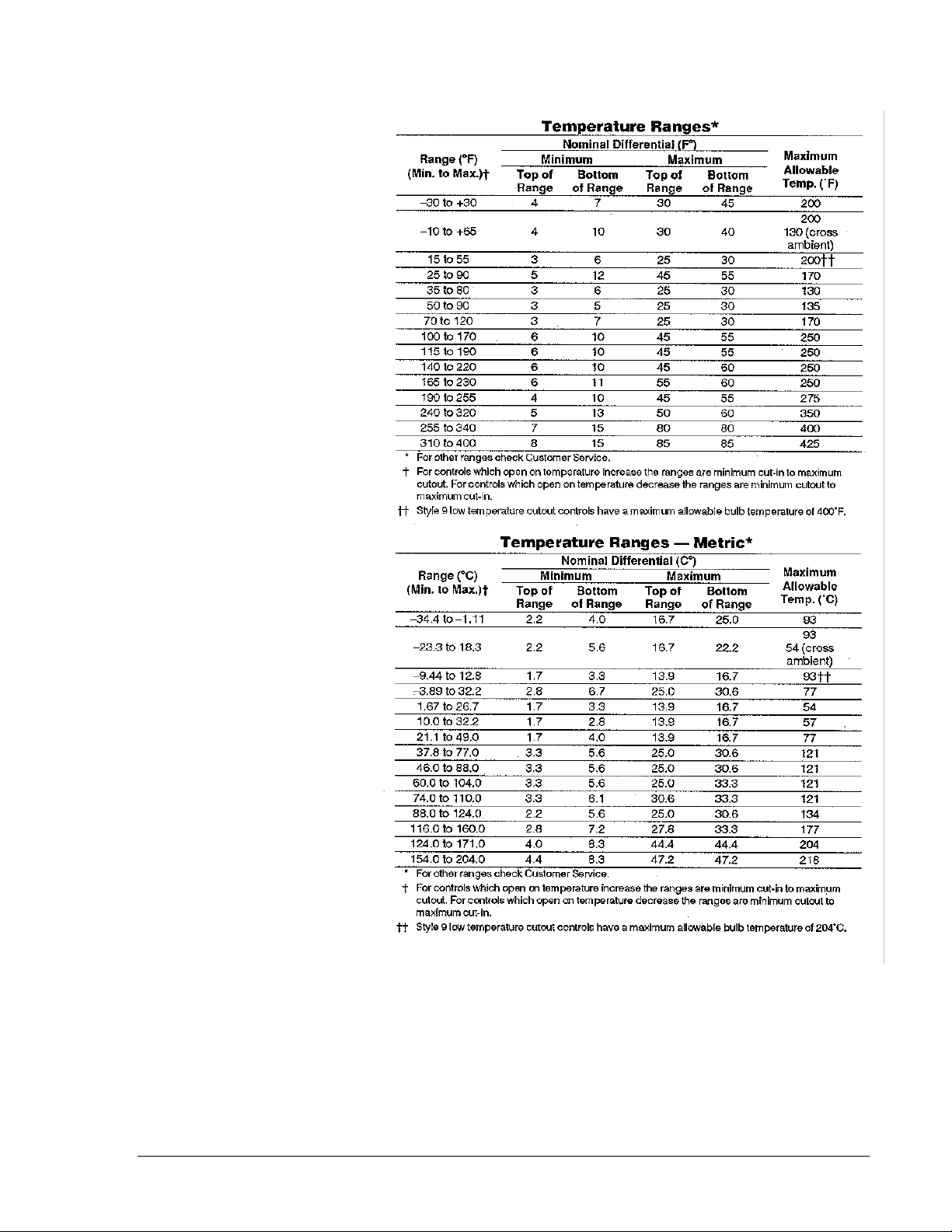
wide selection of ranges to meet
most application needs. See
“Temperature Ranges.”
Models may be supplied to open
a circuit on temperature increase
or close a circuit on temperature
increase as required. An A70
single-pole control may optionally
include a separate reverse-acting
auxiliary contact. Models are
available with a SPDT enclosed
Pennswitch.
All Series A70, A72 controls are
designed for use
operating controls. Where an
operating control failure would
result in personal injury and/or
loss of property, it is the
responsibility of the installer to
add devices (safety, limit
controls) or systems (alarm,
supervisory systems) that
protect against, or warn of,
control failure.
only
as
Specifications
Features
•
Long life contact structure with
high contact force right up to
break -- no bounce on make.
•
Make reset models are
“trip-free”.
•
Ranges available to cover
most applications.
•
Auxiliary contact can be used
to actuate an alarm circuit
when the main contact opens.
•
Two-pole construction
provides a number of
application advantages (see
“General Description”).
•
Heavy gauge “low profile”
stainless steel element cup to
protect against mechanical
damage.
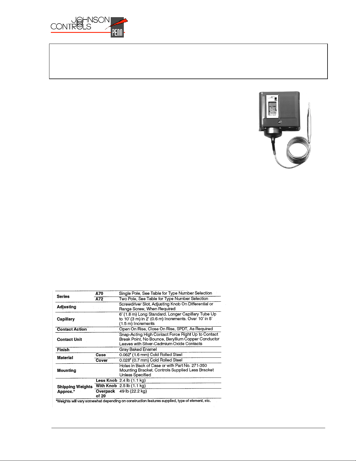
Fig. 1 -- Single function
temperature control, Style 1.
General Description
The A70 controls provide
dependability and quality at
attractive prices. The A72 DPST
controls provide a number of
application advantages such as:
• Control of polyphase motors
without use of magnetic
starters where protection
against overloading and single
phasing is otherwise provided.
• Provides two separate control
circuits necessary for the
control of multiple systems.
• One set of contacts breaks the
“hot” line when wired as a twopole switch in single-phase
circuits.
• Permits control of two
separate load circuits.
• Automatic control of heavy
electrical loads.
• All A70, A72 controls have a
single calibrated scale which
shows directly both cut-in and
cutout settings. Adjustments
can be made readily without
removing the cover.
© 1996 Johnson Controls, Inc.
Code No. LIT-125155
1
Page 2
Optional Constructions
Adjusting Knobs
May be supplied on differential or
range adjusting screw for limited
adjustment within specified limits.
Adjustment Cutout Stops
Cutout stops, factory set as
specified.
Bulb and Capillary
Standard bulb and capillary are
copper. Stainless steel, monel
and steel bulbs are available, if
required. Bulb and capillary with
neoprene coating to military
specifications MIL-R-3065, Grade
SB-515-ABFF may be supplied at
additional cost. Capillary length
6 ft (1.8 m) only.
Covers
Standard finish is gray enamel.
Stainless steel covers available at
slight additional cost for exposed
installations.
Fungus Proofing
Supplied at extra cost, when
specified. Conforms to
government specifications
MIL-V-173A.
Manual Reset
Provides lockout which requires
manual reset before a restart is
possible. Manual reset is “tripfree” and cannot be blocked or
tied down. Button must be
pressed and released before
operation will resume.
Metric Scale Plates
Temperature models are available
with Celsius plates.
Mounting Brackets
Controls are supplied less bracket
unless specified. Controls may
be supplied with mounting
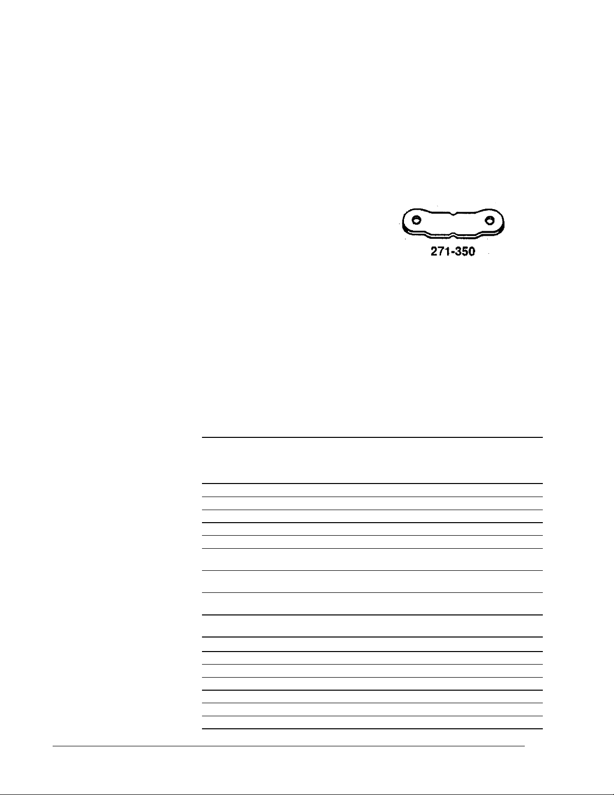
brackets at additional cost. Part
No. 271-350 is standard.
Fig. 2 -- Standard mounting
bracket
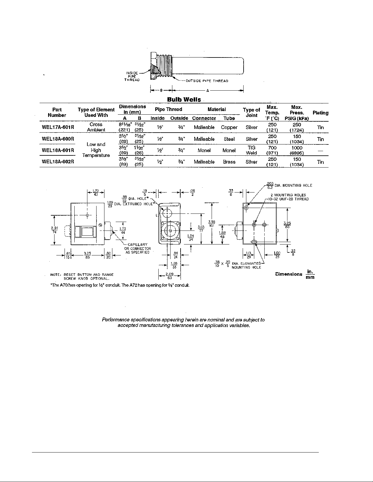
Bulb Wells
Supplied at extra cost, when
specified.
Capillary Tubing
Standard temperature elements
supplied with 6 ft (1.8 m) capillary.
Extra length tube available at
additional cost. Longer capillary
tube supplied up to 10 feet (3 m)
in 2 foot (0.6 m) increments; over
10 feet (3 m) in 5 foot (1.5 m)
increments.
Contact Action
Open on rise or close on rise as
specified.
Type
Number
Single-Pole
A70AA
A70AQ
A70BA
A70DA
A70GA
A70HA
A70JA
A70KA
Two-Pole
A72AA
A72AC
A72AE
A72AP
A72CA
A72CE
Temperature Elements
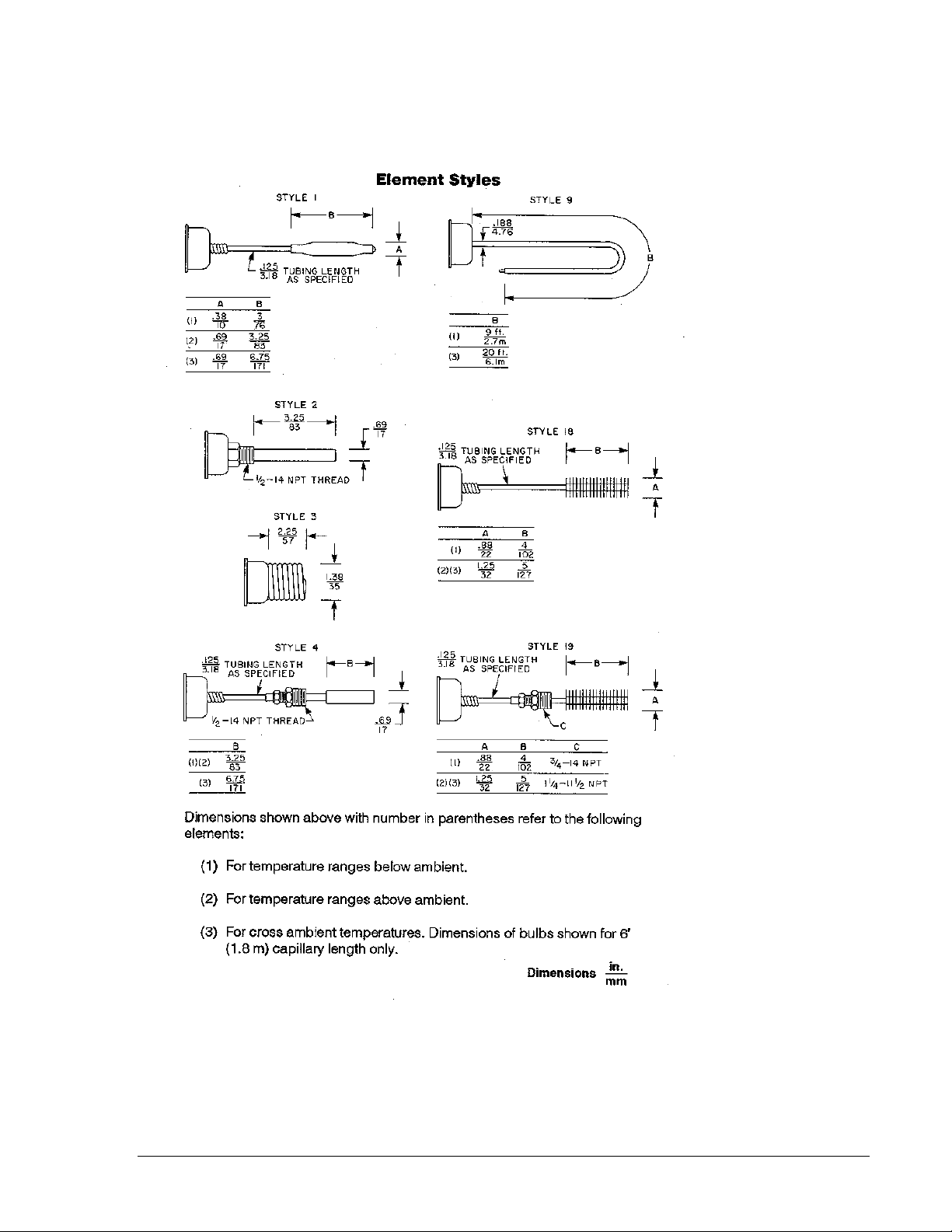
Standard temperature element
styles are shown on Page 5. For
styles other than shown, please
check with the nearest Johnson
Controls district office or
Customer Service.
Type Number Selection
Main
Contact
Action
Open Low 1 No No 1/2 in.
Open Low 1 No Yes 1/2 in. Manual Start
Open Low 1 Yes No 1/2 in.
Open High 1 Yes No 1/2 in.
Open Low 1 No No 1/2 in. Reverse Acting
Open Low 1 Yes No 1/2 in. Reverse Acting
Open High 1 N o No 1/2 in. Reverse Acting
Open High 1 Yes No 1/2 in. Reverse Acting
Open Low 2 No No 3/4 in.
Open Low 2 No No 3/4 in. No Cover
Open Low 2 No No 3/4 in. Outdoor Case
Open Low 2 No No 3/4 in. Manual Start
Open High 2 N o No 3/4 in.
Open High 2 N o No 3/4 in. Outdoor Case
No.
of
Poles
Lockout
with
Manual
Reset
Knob Conduit
Opening
Misc.
Aux. Contact
Aux. Contact
Aux. Contact
Aux. Contact
2 A70, A72 Product Bulletin
Page 3
Repairs and Replacements
Field repairs must not be made
except for replacement of the
cover or knob. For a replacement
control, cover or knob contact the
nearest Johnson Controls
wholesaler.
Ordering Information
When ordering, please specify:
1. Quantity on order.
2. Product Number if available.
3 If Product Number is not
available, specify Type
Number and the following
specifications:
a. Temperature range.
b. Style of element.
Indicate whether
standard or cross
ambient
material and tubing
(copper, steel, stainless
or model).
4. Setting -- switch contacts to
close at __ and open at __.
5. If accessories are desired -mounting bracket, manual
reset, external knob or bulb
well.
6. If external adjusting knob is
required, specify if on
differential or range screw.
element -- bulb
A70, A72 Product Bulletin 3
Page 4
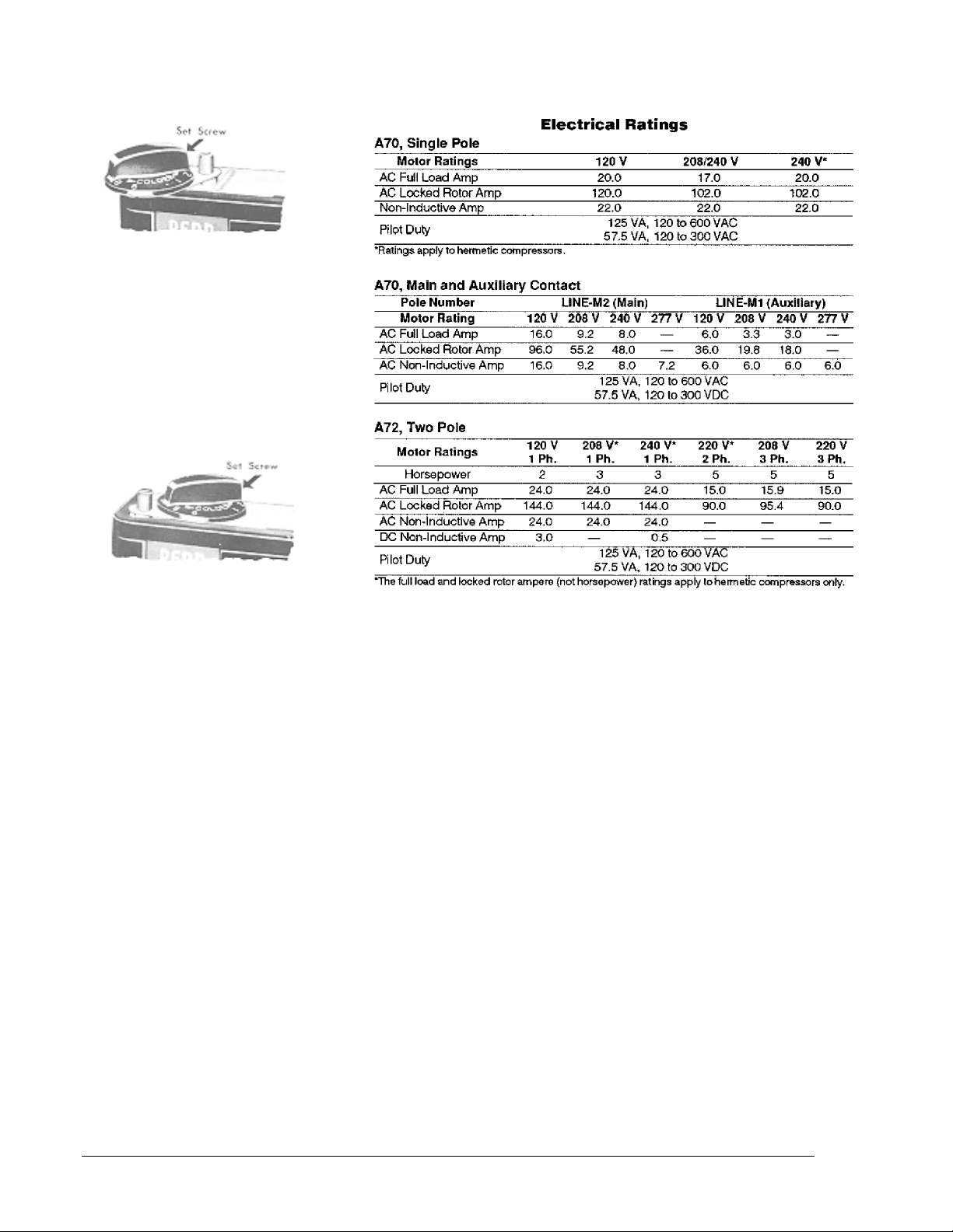
Fig. 3 -- Where it is desirable for
the user to increase or decrease
the DIFFERENTIAL ONLY,
external adjusting knob is
supplied on differential screw as
shown. Knob is provided with
stops and factory assembled to
permit change only within
specified limits.
Fig. 4 -- External adjusting knob
may be placed on range screw,
as shown where it is necessary
for the user to raise or lower both
CUT-IN and CUTOUT points
(differential remains constant).
Knob is provided with stops and
factory assembled to permit
adjustments within
specified limits.
Note: Knob is usually factory
assembled in either position as
shown in Figs. 3 and 4,
depending upon specifications of
original buyer. However, knob
may be changed in the field from
the differential to the range screw
or vice versa by loosening set
screw and removing knob and
indicator plate and reversing their
positions. Assuming that knob is
factory assembled on range
screw (Fig. 4) and set to limit
adjustment to 10°°F (12°°C), this
adjustment will become
approximately 5°°F (-15°°C)
if knob is placed
on differential screw (Fig. 3).
4 A70, A72 Product Bulletin
Page 5
A70, A72 Product Bulletin 5
Page 6
6 A70, A72 Product Bulletin
UL Guide No. SDFY
File SA516
Page 7

Notes
A70, A72 Product Bulletin 7
Page 8

Notes
Controls Group
507 E. Michigan Street
P.O. Box 423 Printed in U.S.A.
Milwaukee, WI 53202
8 A70, A72 Product Bulletin
 Loading...